1
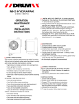
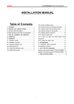
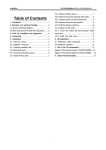
INSTALLATION INSTRUCTIONS
AND
REPAIR PARTS INFORMATION
#111307 LOADER MOUNTING KIT
for mounting DuAl Model 195 Loader to
John Deere 5500 2WD Tractors
#118460 LOADER MOUNTING KIT
for mounting DuAl Model 215 Loader to
John Deere 5500 FWA Tractors
#199758 HYDRAULIC HOSE KIT
for mounting DuAl Model 195 & 215 Loaders to
John Deere 5500 Tractors
PN-53661 (Rev. 12/96)
TO THE DEALER:
The loader mounting kit and/or hydraulic hose kit assembly and proper installation to the tractor is
the responsibility of the DuAl dealer. Read manual instructions and safety rules. Make sure all items
on the Pre-Delivery and Delivery Check Lists in the loader manual are completed before releasing
equipment to the owner.
TO THE OWNER:
Read these mounting instructions before installing loader mounting kit and/or hydraulic hose kit. The
information presented will prepare you to do a better and safer job. Keep this document handy for
ready reference. Require all operators to read the loader manual carefully and become acquainted
with all the adjustment and operating procedures before attempting to operate. Replacement
manuals can be obtained from your dealer or by calling 1-800-319-6637, in the USA or Canada only.
The loader mounting kit and/or hydrulic hose kit you have purchased has been carefully engineered
and manufactured to provide dependable and satisfactory use. Like all mechanical products, it will
require cleaning and upkeep. Observe all safety information in this document, the loader and tractor
manuals, and all safety decals on the loader and tractor.
For service, your authorized DuAl dealer has trained mechanics, genuine DuAl service parts, and the
necessary tools and equipment to handle all your needs.
Use only genuine DuAl service parts. Substitute parts will void the warranty and may not meet
standards required for safe and satisfactory operation. Record the model number of your loader
mounting kit and/or hydraulic hose kit below and provide it to your dealer when requesting repair
parts.
Loader Mounting Kit Model:
Hydraulic Hose Kit Model:
Provide this information to your dealer to obtain correct rep
air parts.
Throughout this manual, the term IMPORTANT is used to indicate that failure to observe can cause
damage to equipment. The terms CAUTION, WARNING and DANGER are used in conjunction with
the Safety-Alert Symbol, (a triangle with an exclamation mark), to indicate the degree of hazard for
items of personal safety.
The Safety-Alert Symbol means ATTENTION! BECOME ALERT!
YOUR SAFETY IS INVOLVED!
CAUTION
Denotes a reminder of safety practices or directs attention to
unsafe practices which could result in personal injury if proper
precautions are not taken.
WARNING
Denotes a hazard exists which can result in injury or death if
proper precautions are not taken.
DANGER
Denotes an extreme intrinsic hazard exists which would result in
high probability of death or irreparable injury if proper precautions
are not taken.
ii
PN-53661 (Rev. 12/96)
SAFETY RULES
ATTENTION! BECOME ALERT! YOUR SAFETY IS INVOLVED!
WARNING
D Read and understand
Operator’s Manual before
operating (available from
dealer or call 1-800-319-6637).
D Keep others away when
operating loader.
D Do not allow children or
untrained persons to operate
equipment.
D Lower loader to ground, stop
engine, set park brake and
remove key before leaving
tractor seat.
D Failure to follow safety rules
can result in serious injury or
death.
DANGER
SERIOUS INJURY OR DEATH
CAN RESULT FROM CONTACT
WITH ELECTRICAL LINES.
DANGER
WARNING
WARNING
FALLING HAZARD
TO AVOID INJURY
OR DEATH:
D DO NOT WORK FROM OR
ALLOW RIDERS ON LOADER
OR ITS ATTACHMENTS.
WARNING
FALLING LOAD HAZARD
TO AVOID INJURY
OR DEATH:
D Do not handle round bale or
other shiftable load unless
loader is equipped with
approved attachments. (Read
Operator’s Manual.)
D Lift and carry only one bale
at a time.
D Handle raised load with
caution.
D Carry load low.
26-0352
PN-53661 (Rev. 12/96)
ROLLOVERS CAN
RESULT IN INJURY
OR DEATH
D ALWAYS USE ROPS AND
SEAT BELT.
D ADD REAR TRACTOR
BALLAST
D MOVE WHEELS TO WIDEST
SETTING.
D AVOID SLOPE OPERATION.
D OPERATE AT LOW SPEEDS.
D CARRY LOAD LOW.
26-0351
1
CRUSHING HAZARD
TO AVOID INJURY
OR DEATH:
D DO NOT WALK OR WORK
UNDERNEATH A RAISED
LOADER.
D LOWER LOADER TO
GROUND BEFORE LEAVING
TRACTOR SEAT.
26-0350
SAFETY RULES
ATTENTION! BECOME ALERT! YOUR SAFETY IS INVOLVED!
PREPARATION
Safety is a primary concern in the design and
manufacture of our products. Unfortunately, our
efforts to provide safe equipment can be wiped
out by a single careless act of an operator.
J Air in hydraulic systems can cause
erratic operation and allows loads or equipment components to drop unexpectedly.
Before operating or allowing anyone to
approach the equipment, purge any air in
the system by operating all hydraulic
functions several times after connecting
equipment, connecting hoses, or doing
any hydraulic maintenance.
In addition to the design and configuration of
equipment, hazard control and accident prevention are dependent upon the awareness, concern, prudence and proper training of personnel
involved in the operation, transport, maintenance
and storage of equipment.
J After connecting hoses, check that all
control lever positions function as
instructed in the Operator’s Manual. Do not
operate until control lever and equipment
movements are correct.
It has been said “The best safety device is an
informed, careful operator.” We ask you to be
that kind of an operator.
The designed and tested safety of this equipment
depends on it being operated within the limitations as
explained in this manual.
J Protective sleeves must be over hydraulic hoses and securely fastened onto metal
hose fittings as shown in this manual. Replace if damaged or if protective sleeve is
not properly positioned or secured.
INSTALLATION
J During installation, the tractor engine
should be off, the key removed and the
brakes locked. Do not disconnect hydraulic
lines until attachments are removed or
lowered to the ground and system pressure
is released by operating valve levers. Never
operate any hydraulic cylinders during any
phase of the installation process.
J Make sure all hydraulic hoses, fittings
and valves are in good condition and not
leaking before starting power unit or using
equipment. Check and route hoses carefully to prevent damage. Hoses must not
be twisted, bent sharply, kinked, frayed,
pinched, or come into contact with any
moving parts. Operate moveable components through full operational range to
check clearances. Replace any damaged
hoses immediately.
TRAINING
J Safety instructions are important! Read
this manual and the DuAl Loader manual
and follow all safety rules and safety
decals. (Replacement manuals are available from dealer or call 1-800-319-6637.)
Failure to follow instructions or safety rules
can result in serious injury or death.
J If you do not understand any part of
this manual and need assistance, see your
dealer.
J Keep hands and body away from pressurized lines. Use paper or cardboard, not
body parts to check for leaks. Wear safety
goggles. Hydraulic fluid (oil) under pressure
will easily penetrate skin and can cause serious injury or death.
J Make sure that all operating and
service personnel know that in the event
hydraulic fluid penetrates skin, it must be
surgically removed within a few hours by
a doctor familiar with this form of injury, or
gangrene, serious injury or death can
result. CONTACT A PHYSICIAN IMMEDIATELY IF FLUID ENTERS SKIN OR EYES.
J Do not allow children or untrained
persons to operate equipment.
J Your dealer can supply original equipment hydraulic accessories and repair
parts. Substitute parts may not meet original equipment specifications and may be
dangerous.
J Always wear relatively tight and belted
clothing to avoid entanglement in moving
parts. Wear sturdy, rough-soled work
shoes and protective equipment for eyes,
hair, hands, hearing and head.
J Tractor must be equipped with ROPS
or ROPS CAB and seat belt. Keep seat belt
securely fastened. Falling off tractor can
result in death from being run over or
crushed. Keep foldable ROPS systems in
“locked up” position at all times.
J Whenever 3-point implements are attached to tractor, always check full range
of operation for mechanical or hydraulic
hose interference.
(Safety Rules continued on next page)
2
PN-53661 (Rev. 12/96)
SAFETY RULES
ATTENTION! BECOME ALERT! YOUR SAFETY IS INVOLVED!
and all raised components to the ground,
operate valve levers to release any hydraulic pressure, stop engine, set parking brake,
remove key, and unfasten seat belt.
(Safety Rules continued from previous page)
J Ensure shields and guards are properly installed and in good condition. Replace
if damaged.
MAINTENANCE SAFETY
OPERATIONAL SAFETY
J Before dismounting tractor or performing any service or maintenance, disengage
power to implement, lower the 3-point hitch
and all raised components to the ground,
operate valve levers to release any hydraulic pressure, stop engine, set parking brake,
remove key, and unfasten seat belt.
J Your dealer can supply original equipment hydraulic accessories and repair
parts. Substitute parts may not meet original equipment specifications and may be
dangerous.
J Always wear relatively tight and belted
clothing to avoid entanglement in moving
parts. Wear sturdy, rough-soled work
shoes and protective equipment for eyes,
hair, hands, hearing and head.
J Keep all persons away from operator
control area while performing adjustments, service or maintenance.
J Tighten all bolts, nuts and screws, and
check that all cotter pins are installed
securely to ensure equipment is in a safe
condition before operating.
J Ensure shields and guards are properly installed and in good condition. Replace
if damaged.
J Protective sleeves must be over hydraulic hoses and securely fastened onto metal
hose fittings as shown in this manual. Replace if damaged or if protective sleeve is
not properly positioned or secured.
J Keep bystanders away from equipment while it is in operation.
J Do not modify or alter or permit anyone
else to modify or alter the loader, loader
mounting kit, any of its components or any
loader function.
J Tractor must be equipped with ROPS
or ROPS CAB and seat belt. Keep seat belt
securely fastened. Falling off tractor can
result in death from being run over or
crushed. Keep foldable ROPS systems in
“locked up” position at all times.
J Always sit in tractor seat when operating controls or starting engine. Securely
fasten seat belt, place transmission in park
or neutral, engage brake and ensure all
other controls are disengaged before
starting tractor engine.
J Before dismounting tractor or performing any service or maintenance, disengage
power to implement, lower the 3-point hitch
NOTES
PN-53661 (Rev. 12/96)
3
BOLT SIZE CHART
NOTE: Chart shows bolt thread sizes and corresponding head (wrench) sizes for standard SAE and Metric Bolts.
SAE Bolt Thread Sizes
5/16
IN
MM
3/8
1/2
5/8
3/4
7/8
1
2
3
4
5
6
7
25
50
75
100
125
150
175
Metric Bolt Thread Sizes
8MM
10MM
12MM
14MM
16MM
18MM
ABBREVIATIONS
ATF . . . . . . . . . Automatic Transmission Fluid
NC . . . . . . . . . . . . . . . . . . . . . National Coarse
CE . . . . . . . . . . . . . . . . Conforms to European
Community Machinery Safety
Directive 89/392/EEC
NF . . . . . . . . . . . . . . . . . . . . . . . . National Fine
NPSM . . . . . . . . . . . . . National Pipe Straight
Mechanical
CV . . . . . . . . . . . . . . . . . . . . Constant Velocity
NPT . . . . . . . . . . . . . . . National Pipe Thread
F . . . . . . . . . . . . . . . . . . . . . . . . . . . . . . Female
P . . . . . . . . . . . . . . . . . . . . . . . . . . . . . . . . Pitch
GA . . . . . . . . . . . . . . . . . . . . . . . . . . . . . . Gauge
psi . . . . . . . . . . . . . . Pounds per Square Inch
GR (5, etc.) . . . . . . . . . . . . . . . Grade (5, etc.)
PTO . . . . . . . . . . . . . . . . . . . . Power Take Off
GPM . . . . . . . . . . . . . . . . . Gallons Per Minute
ROPS . . . . . . . . . . . . . . . Roll Over Protective
Structure
HT . . . . . . . . . . . . . . . . . . . . . . . . Heat Treated
m . . . . . . . . . . . . . . . . . . . . . . . . . . . . . . . . Meter
mm . . . . . . . . . . . . . . . . . . . . . . . . . . Millimeter
SAE . . . . . . . . . . . . . . Society of Automotive
Engineers
M . . . . . . . . . . . . . . . . . . . . . . . . . . . . . . . . Male
UNC . . . . . . . . . . . . . . . . . . . . . Unified Coarse
MPa . . . . . . . . . . . . . . . . . . . . . . Mega Pascal
UNF . . . . . . . . . . . . . . . . . . . . . . . Unified Fine
N . . . . . . . . . . . . . . . . . . . . . . . . . . . . . . Newton
UNS . . . . . . . . . . . . . . . . . . . . Unified Special
4
PN-53661 (Rev. 12/96)
BOLT TORQUE CHART
After every ten (10) hours of operation, check all hardware and tighten where required.
SAE Series Torque Chart
DO NOT use these values if a different torque value or tightening procedure is listed for a specific application. Torque values listed
are for general use only.
Fasteners should be replaced with the same grade.
Make sure fastener threads are clean and you properly start thread engagement. This will prevent them from failing when tightening.
SAETORQUE CHART
Bolt Head
Identification
Bolt
Diameter
“A”
SAE Grade 2
(No Dashes)
SAE Grade 5
(3 Radial Dashes)
SAE Grade 8
(6 Radial Dashes)
MARKING ON HEAD
SAE 5
Lbs.-Ft.
(N-m)
11
(15)
SAE 2
1/4”
Wrench
Size
7/16”
Lbs.-Ft.
6
(N-m)
(8)
5/16”
1/2”
13
(18)
21
3/8”
9/16”
23
(31)
7/16”
5/8”
37
(50)
SAE 8
Lbs.-Ft.
14
(N-m)
(19)
(28)
25
(34)
38
(52)
55
(75)
55
(75)
80
(110)
1/2”
3/4”
57
(77)
85
(115)
120
(165)
9/16”
13/16”
82
(111)
125
(170)
180
(245)
5/8”
15/16”
111
(150)
175
(240)
230
(310)
3/4”
1-1/8”
200
(270)
300
(410)
440
(600)
7/8”
1-5/16”
280
(380)
450
(610)
720
(975)
1”
1-1/2”
350
(475)
680
(925)
1035
(1400)
1-1/8”
1-11/16”
450
(610)
885
(1200)
1-1/4”
1-7/8”
600
(815)
1255
(1700)
1-3/8”
2-1/16”
675
(915)
1620
(2200)
1-1/2”
2-1/4”
920
(1250)
2200
(2900)
A
Bolt
Diameter
Metric Series Torque Chart
Use only metric tools on metric hardware. Other tools may not fit properly. They may slip and cause injury.
DO NOT use these values if a different torque value or tightening procedure is listed for a specific application.
Torque values listed are for general use only.
Fasteners should be replaced with the same grade.
Make sure fastener threads are clean and you properly start thread engagement. This will prevent them from failing when tightening.
Bolt
Diameter
“A”
MARKING ON HEAD
8.8
10.9
5 mm
Wrench
Size
8 mm
N-m
6
(Lbs.-Ft.)
(4.5)
N-m
9
(Lbs.-Ft.)
(6.5)
6 mm
10 mm
10
(7.5)
15
(11)
8 mm
13 mm
25
(18)
35
(26)
10 mm
16 mm
50
(37)
75
(55)
12 mm
18 mm
85
(63)
130
(97)
14 mm
21 mm
110
(80)
150
(110)
16 mm
24 mm
215
(159)
315
(232)
20 mm
30 mm
435
(321)
620
(457)
24 mm
36 mm
750
(553)
1070
(789)
30 mm
46 mm
1495
(1103)
2130
(1571)
PN-53661 (Rev. 12/96)
5
Metric
Bolt Head
Identification
Metric
Grade 8.8
Metric
Grade 10.9
MOUNTING INSTRUCTIONS
Front Mount Attachment -- 195 Loader
Safety is a primary concern in the design and
manufacture of our products. Unfortunately, our
efforts to provide safe equipment can be wiped
out by a single careless act of an operator.
Attach the front mount (1) to the front of the tractor
bolster and secure with four cap screws (16) and
lockwashers (15). Tighten all fasteners securely.
In addition to the design and configuration of
equipment, hazard control and accident prevention are dependent upon the awareness, concern, prudence and proper training of personnel
involved in the operation, transport, maintenance
and storage of equipment.
It has been said “The best safety device is an
informed, careful operator.” We ask you to be
that kind of an operator.
The 111307 Loader Mounting Kit fits John Deere 5500
tractors for use with a DuAl 195 Loader. The 118460
Loader Mounting Kit fits John Deere 5500 tractors for
use with a DuAl 215 loader. The 199758 Hydraulic
Hose Kit fits John Deere 5500 tractors with 195 or 215
Loaders. Refer to DuAl 195 or 215 Loader Operator’s
Manual for loader assembly instructions. Use
instructions in this manual for installing loader
mounting kits and hydraulic hose kit.
15 16
1
CM581
1. Front Mount
15. 3/4”Lockwasher
16. 3/4 NC x 3”Hex head cap screw GR5
Figure 1. Front Mount Attachment -- 195 Loader
Shut off engine and set parking brake during
installation.
If equipped, remove the front end weight bracket and
toolbox from tractor.
Front Mount Attachment -- 215 Loader
WARNING
Attach the right front mount (5) to the tractor frame and
secure with two cap screws (19) and lockwashers (12).
Repeat for opposite side. Tighten all fasteners securely.
J Safety instructions are important!
Read this manual and the DuAl Loader
manual and follow all safety rules and
safety decals. (Replacement manuals are
available
from
dealer
or
call
1-800-319-6637.) Failure to follow instructions or safety rules can result in serious
injury or death.
J Do not modify or alter or permit anyone else to modify or alter the loader,
loader mounting kit, any of its components or any loader function.
J Keep all persons away from operator
control area while performing adjustments, service or maintenance.
5
19 12
CAUTION
CM682
5. Right front mount
12. 5/8”Lockwasher
19. 5/8 NC x 2”Hex head cap screw GR5
J Always wear relatively tight and belted
clothing to avoid entanglement in moving
parts. Wear sturdy, rough-soled work
shoes and protective equipment for eyes,
hair, hands, hearing and head.
Figure 2. Front Mount Attachment -- 215 Loader
6
PN-53661 (Rev. 12/96)
Rear Mount Attachment -- 215 Loader
To provide clearance for mounting the 215 loader,
adjust the front tractor tires to a minimum 67”tread or
to the manufacturer’s widest recommended setting.
This also provides increased tractor stability.
Attach the front of the left rear mount (3) to the tractor
frame as shown and secure with two cap screws (14),
washers (13) and lockwashers (12). Secure the rear of
the left rear mount to the tractor with four cap screws
(18) and lockwashers (17). Repeat for opposite side. Do
not tighten fasteners until all adjustments are complete.
17 18
67”
MINIMUM
SC686
14
13
12
Figure 3. Tire Adjustment -- 215 Loader Only
3.
12.
13.
14.
17.
18.
Rear Mount Attachment -- 195 Loader
Attach the front of the left rear mount (3) to the side of
the tractor frame as shown and secure with two cap
screws (14), washers (13) and lockwashers (12).
Secure the rear of the left rear mount to the tractor
with four cap screws (18) and lockwashers (17).
Repeat for opposite side. Do not tighten fasteners
until all adjustments are complete.
Attach the crossmember link (4) to the rear mounts as
shown and secure with cap screws (11), washers
(13), lockwashers (12) and hex nuts (10). Tighten all
fasteners securely.
4
13 12 11 10
CM583
Left rear mount
5/8”Lockwasher
5/8”Standard flat washer
16mm x 2P x 35mm Hex head cap screw
20mm Lockwasher
20mm x 2.5P x 50mm Hex head cap screw
CM582
4.
10.
11.
12.
13.
Figure 4. Rear Mount Attachment -- 195 Loader
PN-53661 (Rev. 12/96)
Left rear mount
5/8”Lockwasher
5/8”Standard flat washer
16mm x 2P x 35mm Hex head cap screw
20mm Lockwasher
20mm x 2.5P x 50mm Hex head cap screw
GR5
Crossmember Link Attachment
3
3.
12.
13.
14.
17.
18.
CM684
Figure 5. Rear Mount Attachment -- 215 Loader
17 18
12 13 14
3
.50 x 6.00 x 18.87”U-Link
14mm x 1.5P Hex nut
14mm x 1.5P x 50mm Hex head cap screw
5/8”Lockwasher
5/8”Standard flat washer
Figure 6. Crossmember Link Attachment
7
Hydraulic Hose Installation Instructions
Refer to illustration on page 10 for the proper orientation of the hoses.
Connect the end of the hose with the quick disconnect
coupler into the female couplers on the rear of the
tractor to complete the circuit, as shown in Figure 7.
WARNING
J Keep hands and body away from pressurized lines. Use paper or cardboard, not
body parts to check for leaks. Wear safety
goggles. Hydraulic fluid (oil) under pressure will easily penetrate skin and can
cause serious injury or death.
D
C
B
A
J Make sure that all operating and
service personnel know that in the event
hydraulic fluid penetrates skin, it must be
surgically removed within a few hours by
a doctor familiar with this form of injury, or
gangrene, serious injury or death can
result. CONTACT A PHYSICIAN IMMEDIATELY IF FLUID ENTERS SKIN OR EYES.
J Make sure all hydraulic hoses, fittings
and valves are in good condition and not
leaking before starting power unit or using
equipment. Check and route hoses carefully to prevent damage. Hoses must not
be twisted, bent sharply, kinked, frayed,
pinched, or come into contact with any
moving parts. Operate moveable components through full operational range to
check clearances. Replace any damaged
hoses immediately.
Figure 7. Hose Connection to Tractor
Once all hoses are connected, start the tractor and
run the loader valve lever to check for leaks and purge
any remaining air from the hydraulic system.
Check to be sure the valve handle directions
correspond with the motion of the loader. See chart
on page 11.
J Air in hydraulic systems can cause
erratic operation and allows loads or
equipment components to drop unexpectedly. Before operating or allowing anyone
to approach the equipment, purge any air
in the system by operating all hydraulic
functions several times after connecting
equipment, connecting hoses, or doing
any hydraulic maintenance.
Once all hose routings are verified, identify each
circuit by placing a matching colored band around the
male and female quick disconnect couplers. The color
coded bands will make re-installation easier when the
loader is removed from the tractor.
Attach the plastic tie straps (included in kit) around
the hoses to keep them tightly bundled and away from
contact with the ground or other moving parts on the
tractor or loader. Be sure that adequate slack is left in
the hoses so they can move as the loader moves
through it’s full range of motion.
Refer to page 11. A hose kit is available that will
attach the loader feed lines directly into the rear
tractor hydraulic ports. Prepare each hose assembly
(1) by attaching a 90° swivel (2) and male quickdisconnect (3) onto the end of hose (without protector
sleeve). Attach the opposite end of the hydraulic hose
(with protector sleeve) into the loader feed lines.
Refer to either the 195 or 215 Loader Operator’s
Manual to complete the loader installation.
8
PN-53661 (Rev. 12/96)
#111307 LOADER MOUNTING KIT
18
17
11
2
4
13
12
10
3
1
CD4941
13
15
16
Ref
Part
No
No
1
53631
2 53306-1
3 53307-1
4
53264
No
Used
1
1
1
1
Description
Front mount
Right rear mount
Left rear mount
.50 x 6.00 x 18.87 U-Link
Part
No
12
1286 *
5/8 Lockwasher, plated
13
692 *
5/8 Flat washer plated
15
Ref
No
10
11
Part
No
43104 *
65541
Description
14mm x 1.5P Hex nut
14mm x 1.5P x 50mm Hex head cap
screw
PN-53661 (Rev. 12/96)
14
Ref
No
14
HARDWARE
12
23446
2522 *
16mm x 2.0P x 35mm Hex head cap
screw
3/4 Lockwasher
16
14334
17
308020
20mm Lockwasher, plated
18
307553
20mm x 2.5P x 50mm Hex head cap
screw
*Obtain Locally
9
Description
3/4 NC x 3 Hex head cap screw GR5
#118460 LOADER MOUNTING KIT
18
17
11
2
4
13
12
10
3
CD4942
5
13
12
19
12
14
6
Ref
No
2
3
4
5
6
Ref
No
10
11
Part
No
53808
53809
53264
53820
53821
Part
No
43104 *
65541
No
Used
1
1
1
1
1
Description
Right rear mount
Left rear mount
.50 x 6.00 x 18.87 U-Link
Right front mount
Left front mount
HARDWARE
Description
14mm x 1.5P Hex nut
14mm x 1.5P x 50mm Hex head cap
screw
Ref
No
Part
No
12
1286 *
5/8 Lockwasher, plated
13
692 *
5/8 Flat washer plated
Description
14
23446
17
308020
20mm Lockwasher plated
18
307553
20mm x 2.5P x 50mm Hex head cap
screw
19
902 *
16mm x 2.0P x 35mm Hex head cap
screw
5/8 NC x 2 Hex head cap screw GR5
*Obtain Locally
10
PN-53661 (Rev. 12/96)
#199758 HYDRAULIC HOSE KIT
215 LOADER
D
195 LOADER
B
A
D
C
C
B
A
2
3
D
CD4943
C
B
A
1
Ref
No
Part
No
No
Used
1
53670
4
Hose -- 3/8, 150”, 3/4 JICM x 3/4
JICM with vinyl protector
2
31-3053
4
90°Swivel elbow
3
66511
4
Quick coupler -- male
Description
Part
No
39-5063
39-5062
39-5061
89
Items Not Shown
No
Used
2
2
2
4
Description
Plastic spiral band -- orange
Plastic spiral band -- blue
Plastic spiral band -- red
Plastic tie
LOADER VALVE FUNCTION CHART
HANDLE FORWARD
BOOM DOWN
HANDLE REARWARD
BOOM UP
HANDLE LEFT
BUCKET ROLLBACK
HANDLE RIGHT
BUCKET DUMP
PN-53661 (Rev. 12/96)
11
NOTES
12
PN-53661 (Rev. 12/96)
WARRANTY
Please enter information below and SAVE FOR FUTURE REFERENCE.
Date Purchased:
From (Dealer):
Model Number:
Serial Number:
WOODS warrants each new WOODS product to be free from defects in material and workmanship.
This warranty is applicable only for the normal service life expectancy of the machine or components,
not to exceed twelve consecutive months from the date of delivery of the new WOODS product to the
original purchaser.
Genuine WOODS replacement parts and components will be warranted for 90 days from date of
purchase, or the remainder of the original equipment warranty period, whichever is longer.
Under no circumstances will it cover any merchandise or components thereof, which, in the opinion
of the company, has been subjected to negligent handling, misuse, alteration, an accident, or if repairs
have been made with parts other than those obtainable through WOODS.
The company in no way warrants engines, batteries, tires or other trade accessories since these items
are warranted separately by their respective manufacturers.
Our obligation under this warranty shall be limited to repairing or replacing, free of charge to the
original purchaser, any part that in our judgement shall show evidence of such defect, provided further
that such part shall be returned within thirty (30) days from date of failure to WOODS, routed through
the dealer and distributor from whom the purchase was made, transportation charges prepaid.
This warranty shall not be interpreted to render us liable for injury or damages of any kind or nature
to person or property. This warranty does not extend to loss of crops, loss because of delay in
harvesting, or any expense or loss incurred for labor, supplies, substitute machinery, rental or for any
other reason.
Except as set forth above, WOODS SHALL HAVE NO OBLIGATION OR LIABILITY OF ANY KIND
ON ACCOUNT OF ANY OF ITS EQUIPMENT AND SHALL NOT BE LIABLE FOR SPECIAL OR
CONSEQUENTIAL DAMAGES. WOODS MAKES NO OTHER WARRANTY, EXPRESS OR
IMPLIED, AND, SPECIFICALLY, WOODS DISCLAIMS ANY IMPLIED WARRANTY OF
MERCHANTABILITY OR FITNESS FOR A PARTICULAR PURPOSE. SOME STATES OR
PROVINCES DO NOT PERMIT LIMITATIONS OR EXCLUSIONS OF IMPLIED WARRANTIES OR
INCIDENTAL OR CONSEQUENTIAL DAMAGES, SO THE LIMITATIONS OR EXCLUSIONS IN THIS
WARRANTY MAY NOT APPLY.
This warranty is subject to any existing conditions of supply which may directly affect our ability to
obtain materials or manufacture replacement parts.
WOODS reserves the right to make improvements in design or changes in specifications at any time,
without incurring any obligations to owners of units previously sold.
No one is authorized to alter, modify, or enlarge this warranty nor the exclusions, limitations and
reservations.
Woods Equipment
Company
2606 Illinois Route 2 South
Post Office Box 1000
Oregon, Illinois 61061
815-732-2141 tel
815-732-7580 fax
F-3079 (Rev. 4/96) STD
PART NUMBER
53661
Woods Equipment
Company
2606 Illinois Route 2 South
Post Office Box 1000
Oregon, Illinois 61061
815-732-2141 tel
815-732-7580 fax
LITHO IN USA