1
1001378 SUB-FRAME MOUNTING KIT
Woods Backhoe Model:
BH9000
mounting to
John Deere Tractor Models:
5200, 5300, 5400, 5500
5210, 5310, 5410, 5510
With and Without Cab
equipped with:
John Deere Loaders
520
540
Woods Loaders
1020
1027
MANUAL
PART NUMBER
MAN0047
MAN0047 (Rev. 11/22/00)
TO THE DEALER:
Assembly and proper installation of this product is the responsibility of the WOODS dealer. Read manual instructions
and safety rules. Make sure all items on the Dealer’s Pre-Delivery and Delivery Check Lists in the Operator’s Manual
are completed before releasing equipment to the owner.
The dealer must complete the Warranty Registration included in this manual. Both dealer and customer must sign the
registration which certifies that all Dealer Check List items have been completed. The dealer is to return the prepaid
postage portion to WOODS, give one copy to the customer, and retain one copy. Note: Warranty credit is subject to
this form being completed and returned.
TO THE OWNER:
Read this manual before operating your WOODS equipment. The information presented will prepare you to do a better
and safer job. Keep this manual handy for ready reference. Require all operators to read this manual carefully and
become acquainted with all the adjustment and operating procedures before attempting to operate. Replacement
manuals can be obtained from your dealer or, in the United States and Canada, by calling 1-800-319-6637.
The equipment you have purchased has been carefully engineered and manufactured to provide dependable and
satisfactory use. Like all mechanical products, it will require cleaning and upkeep. Lubricate the unit as specified.
Observe all safety information in this manual and safety decals on the equipment.
For service, your authorized WOODS dealer has trained mechanics, genuine WOODS service parts, and the
necessary tools and equipment to handle all your needs.
Use only genuine WOODS service parts. Substitute parts will void the warranty and may not meet standards required
for safe and satisfactory operation. Record the model number and serial number of your equipment in the spaces
provided:
Model: #1001378 Sub-Frame Mounting Kit
Date of Purchase: _____________________
Serial Number: (see Parts List section for location) _______________________________________
Provide this information to your dealer to obtain correct repair parts.
Throughout this manual, the term IMPORTANT is used to indicate that failure to observe can cause damage to
equipment. The terms CAUTION, WARNING and DANGER are used in conjunction with the Safety-Alert Symbol, (a
triangle with an exclamation mark), to indicate the degree of hazard for items of personal safety.
This Safety-Alert Symbol indicates a hazard and means
ATTENTION! BECOME ALERT! YOUR SAFETY IS INVOLVED!
Indicates an imminently hazardous situation that, if not avoided, will
result in death or serious injury
Indicates a potentially hazardous situation that, if not avoided,
could result in death or serious injury, and includes hazards that are
exposed when guards are removed.
Indicates a potentially hazardous situation that, if not avoided, may
result in minor or moderate injury.
Indicates that failure to observe can cause damage to equipment.
NOTE
Indicates helpful information.
ii
MAN0047 (9/15/00)
SAFETY RULES
ATTENTION! BECOME ALERT! YOUR SAFETY IS INVOLVED!
Safety is a primary concern in the design and
manufacture of our products. Unfortunately, our
efforts to provide safe equipment can be wiped
out by an operator’s single careless act.
In addition to the design and configuration of
equipment, hazard control and accident prevention are dependent upon the awareness, concern,
judgement, and proper training of personnel
involved in the operation, transport, maintenance
and storage of equipment.
It has been said “The best safety device is an
informed, careful operator.” We ask you to be that
kind of operator.
INSTALLATION
n This Sub-Frame Mounting Kit is to be used only
for the backhoes and tractors specified in the SubFrame Mount Installation section of this manual.
Any other use or modification of this mounting kit
may result in serious injury or death.
n Hydraulics must be connected as instructed in
this manual. Do not substitute parts, modify, or
connect in any other way.
n After connecting hoses, check that all control
lever positions function as instructed in the Operator’s Manual. Do not put into service until control
lever and equipment movements are correct.
TRAINING
n Safety instructions are important! Read all
attachment and power unit manuals; follow all
safety rules and safety decal information. (Replacement manuals are available from dealer or, in the
United States and Canada, call 1-800-319-6637.)
Failure to follow instructions or safety rules can
result in serious injury or death.
n If you do not understand any part of this manual
and need assistance, see your dealer.
n Know your controls and how to stop engine and
attachment quickly in an emergency.
n Keep hands and body away from pressurized
lines. Use paper or cardboard, not hands or other
body parts to check for leaks. Wear safety goggles.
Hydraulic fluid under pressure can easily penetrate
skin and will cause serious injury or death.
n Make sure that all operating and service personnel know that if hydraulic fluid penetrates skin, it
must be surgically removed as soon as possible by
a doctor familiar with this form of injury or gan-
BH9000 SFMK (11/1/00)
grene, serious injury, or death will result. CONTACT
A PHYSICIAN IMMEDIATELY IF FLUID ENTERS
SKIN OR EYES. DO NOT DELAY.
n Never allow children or untrained persons to
operate equipment.
PREPARATION
n Check that all hardware is properly installed.
Always tighten to torque chart specifications
unless instructed otherwise in this manual.
n Air in hydraulic systems can cause erratic operation and allow loads or equipment components to
drop unexpectedly. When connecting equipment or
hoses or performing any hydraulic maintenance,
purge any air in hydraulic system by operating all
hydraulic functions several times. Do this before
putting into service or allowing anyone to approach
the equipment.
n After connecting hoses, check that all control
lever positions function as instructed in the Operator’s Manual. Do not put into service until control
lever and equipment movements are correct.
n Protective hose sleeves must cover all hydraulic
hoses and be secured onto metal hose fittings.
Replace hoses or sleeves if damaged or if protective sleeve cannot be properly positioned or
secured.
n Make sure all hydraulic hoses, fittings, and
valves are in good condition and not leaking before
starting power unit or using equipment. Check and
route hoses carefully to prevent damage. Hoses
must not be twisted, bent sharply, kinked, frayed,
pinched, or come into contact with any moving
parts. Operate moveable components through full
operational range to check clearances. Replace
any damaged hoses immediately.
n Always wear relatively tight and belted clothing
to avoid entanglement in moving parts. Wear
sturdy, rough-soled work shoes and protective
equipment for eyes, hair, hands, hearing, and head.
n Make sure attachment is properly secured,
adjusted, and in good operating condition.
n The sub-frame mount is designed to provide
secure mounting and adequate operator clearance
when properly installed. Check clearance dimensions shown in figure 1 to be sure you have
installed sub-frame correctly. Follow all mounting
instructions in this manual. Do not operate backhoe unless there is adequate clearance. Failure to
SAFETY 1
SAFETY RULES
ATTENTION! BECOME ALERT! YOUR SAFETY IS INVOLVED!
check and comply with these instructions may
result in serious injury or death.
n Remove seat and upper support assembly
before installing or removing backhoe from tractor.
Failure to comply may result in equipment failure
and/or personal injury.
n Always use the special heavy-duty top link (provided with backhoe) and the OEM high-strength top
link pin (provided with tractor) to mount top link to
tractor. Use a 1” x 5” grade 5 bolt to mount top link
to backhoe.
n If tractor is equipped with draft sensing control,
set control to “HEAVY” (minimum sensitivity) position.
n On tractors equipped with optional “Draft Control Hitch,” you must install the “Draft Lockout”
(provided in sub-frame kit) into position as shown.
Failure to install the “Draft Lockout” will allow
upper hitch to move during backhoe operation and
could result in operator injury.
n Make sure all safety decals are installed.
Replace if damaged. (See Safety Decals section for
location.)
n A minimum 25% of tractor and equipment
weight must be on the tractor front wheels when
attachments are in transport position. Without this
weight, tractor could tip over, causing personal
injury or death. The weight may be attained with a
loader, front wheel weights, ballast in tires, or front
tractor weights. Weigh the tractor and equipment.
Do not estimate.
OPERATION
• Read Sub-Frame Mounting Kit Manual
instructions on attaching and removing backhoe and use extreme care
• Always stand between rear tire and backhoe
stabilizer arms or along side of tractor to avoid
being trapped should the boom swing control
be accidentally activated.
n Never leave equipment unattended with engine
running or with bucket in raised position. Always
engage swing and boom transport locks, relieve
system pressure by operating controls, and
remove ignition key before leaving equipment.
MAINTENANCE
n Refer to backhoe manual and follow all maintenance safety rules and instructions.
n Do not modify or alter or permit anyone else to
modify or alter the equipment or any of its components in any way.
n Your dealer can supply original equipment
hydraulic accessories and repair parts. Substitute
parts may not meet original equipment specifications and may be dangerous.
n Always wear relatively tight and belted clothing
to avoid entanglement in moving parts. Wear
sturdy, rough-soled work shoes and protective
equipment for eyes, hair, hands, hearing, and head.
n Do not allow bystanders in the area when operating, attaching, removing, assembling, or servicing equipment.
n Make sure attachment is properly secured,
adjusted, and in good operating condition.
n Do not allow bystanders in the area when operating, attaching, removing, assembling, or servicing equipment.
n Keep all persons away from operator control
area while performing adjustments, service, or
maintenance.
n Before operating, make sure stabilizer pads are
lowered firmly to the ground. Stabilizer arms provide support for the backhoe and support for the
backhoe mounting brackets.
n Before working on backhoe, extend boom and
dipperstick and place bucket on ground. Make sure
that all system pressure has been relieved by operating controls before performing maintenance or
service or before disconnecting any hydraulic
lines.
n Do not operate equipment while under the influence of alcohol or drugs.
n Always comply with all state and local lighting
and marking requirements.
n Do not allow riders. Do not lift or carry anybody
on the power unit or attachments.
n The only time the backhoe may be operated
from a position other than the operator seat is during backhoe attachment and removal. Operator
must
2 SAFETY
n Tighten all bolts, nuts and screws to torque
chart specifications. Check that all cotter pins are
installed securely to ensure equipment is in a safe
condition before putting unit into service.
n Make sure all safety decals are installed.
Replace if damaged. (See Safety Decals section for
location.)
BH9000 SFMK (11/1/00)
BACKHOE SUB-FRAME INSTALLATION
Safety is a primary concern in the design and
manufacture of our products. Unfortunately, our
efforts to provide safe equipment can be wiped
out by an operator’s single careless act.
In addition to the design and configuration of
equipment, hazard control and accident prevention are dependent upon the awareness, concern,
judgement, and proper training of personnel
involved in the operation, transport, maintenance
and storage of equipment.
It has been said “The best safety device is an
informed, careful operator.” We ask you to be that
kind of operator.
DANGER
n The sub-frame mount is designed to provide
secure mounting and adequate operator clearance
when properly installed. Check clearance dimensions shown in figure 1 to be sure you have
installed sub-frame correctly. Follow all mounting
instructions in this manual. Do not operate backhoe unless there is adequate clearance. Failure to
check and comply with these instructions may
result in serious injury or death.
n The only time the backhoe may be operated
from a position other than the operator seat is during backhoe attachment and removal. Operator
must
• Read Operator's Manual instructions on
attaching and removing backhoe and use
extreme care
• Engage swing lock to prevent boom rotation
• Always stand rearward of backhoe stabilizer
arms or along side of tractor to avoid being
trapped should the boom swing control be accidentally activated.
MAN0047 (9/15/00)
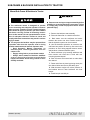
WARNING
■
Only use #1001378 Sub-Frame Mounting Kit for
mounting Woods BH9000 backhoe on John Deere
5200, 5300, 5400, 5210, 5310, 5410 and 5510 tractors equipped with either Woods model 1020/1027
loaders or John Deere 520 and 540 loaders. Any
other use or modification of this mounting kit may
result in serious injury or death.
n Safety instructions are important! Read all
attachment and power unit manuals; follow all
safety rules and safety decal information. (Replacement manuals are available from dealer or, in the
United States and Canada, call 1-800-319-6637.)
Failure to follow instructions or safety rules can
result in serious injury or death.
n Keep all persons away from operator control
area while performing adjustments, service, or
maintenance.
n Before working on backhoe, extend boom and
dipperstick and place bucket on ground. Make sure
that all system pressure has been relieved by operating controls before performing maintenance or
service or before disconnecting any hydraulic
lines.
n A minimum 25% of tractor and equipment
weight must be on the tractor front wheels when
attachments are in transport position. Without this
weight, tractor could tip over, causing personal
injury or death. The weight may be attained with a
loader, front wheel weights, ballast in tires, or front
tractor weights. Weigh the tractor and equipment.
Do not estimate.
n Make sure all hydraulic hoses, fittings, and
valves are in good condition and not leaking before
starting power unit or using equipment. Check and
route hoses carefully to prevent damage. Hoses
must not be twisted, bent sharply, kinked, frayed,
pinched, or come into contact with any moving
parts. Operate moveable components through full
operational range to check clearances. Replace
any damaged hoses immediately.
INSTALLATION 3
SUB-FRAME INSTALLATION Cont’d
CAUTION
n If you do not understand any part of this manual
and need assistance, see your dealer.
n Always wear relatively tight and belted clothing
to avoid entanglement in moving parts. Wear sturdy,
rough-soled work shoes and protective equipment
for eyes, hair, hands, hearing, and head.
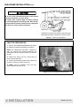
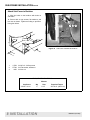
* Operator’s seat must be located in the lowest and
most forward position to obtain 40” minimum radius.
Figure 1 Sub-Frame Clearance
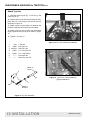
TRACTOR PREPARATION
1. Refer to the WOODS BH9000 Backhoe Operator’s Manual for backhoe assembly instructions.
NOTE: For installing this sub-frame, reference to
right, left, forward and rearward directions are
determined from the operator’s position in the tractor seat.
2. Remove the tractor top link, 3-point lower lift
arms, and anti-sway links.
3. Remove three bolts from both lower 3-point arm
pivot pins, leave pins in place (Figure 2).
4. NOTE: Leave all hardware loose until subframe weldment has been fit up.
Figure 2 Remove hardware from pivot pins
4 INSTALLATION
MAN0047 (9/15/00)
SUB-FRAME INSTALLATION Cont’d
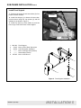
Install Front Support
1. Remove cap screw (4) and hose holder (5) from
bottom of tractor chassis.
Forward
2. Install front hanger (1) to bottom of tractor chassis and secure using four cap screws (2) and flat
washers (3) as shown in Figure 3.
3. Install cap screw (4), hose holder (5) and hex
lock nut (6) to left front corner of front support.
4
2
3
5
6
1
Figure 3 Front Support Installed
1. 1001383
2.
33125
3.
46070
4.
-------5.
-------6. 307825
Front Support
M14 x 2.0P x 50mm Cap screw
9/16 Flat washer, hardened
M14 x 2.0P Cap screw (Tractor)
Hose holder (Tractor)
M14 x 2.0P Hex nut
6
3
1
2
Figure 4 Front Support Installation
MAN0047 (9/15/00)
INSTALLATION 5
SUB-FRAME INSTALLATION Cont’d
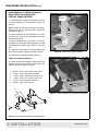
Install Right and Left Rear Supports
Right Rear Support #1001380
Left Rear Support #100381
Pivot Pin
1. Install right rear support by inserting cap screw
(1) and flat washers (2) into position as shown in
Figure 6.
NOTE: Install flat washers between rear support
and pivot pin and on outside at head of cap screw
as shown in Figure 5.
1
2
2. Install cap screw (3) and flat washer (2) in front
hole(Figure 6). Only use one flat washer on outside
at head of cap screw.
3
2
3. Install remaining two cap screws (1) and four
flat washers (2) into position around pivot pin. Install
flat washers both inside and outside of rear support.
4. Install two cap screws (4) and flat washers (5)
into bottom of tractor chassis as shown in Figure 7
Figure 6 Right Rear Support Installed
5. Install left rear support, following steps 1-5.
Install Cross Member #1001387
6. Install cross member between right and left rear
supports using four cap screws (3), flat washers (2)
and hex nuts (6) as shown in Figure 7.
1. 1001575
2.
46070
3.
33125
4.
30743
5.
57817
6. 307825
M14 x 2.0P x 55mm Cap screw
9/16 Flat washer, hardened
M14 X 2.0p X 50 mm Cap screw
M16 x 2.0P x 45mm Cap screw
5/8 Flat washer, hardened
M14 x 2.0P Hex nut
5
4
2
3
6
2
Figure 7 Rear Supports & Cross Member Installed
1
Figure 5 Flat Washer Installation on Rear Support
6 INSTALLATION
MAN0047 (9/15/00)
SUB-FRAME INSTALLATION Cont’d
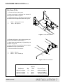
Sub-Frame Fit-Up
1. Center sub-frame under tractor.
2. Insert cross tube of sub-frame into channel of
rear support as shown in Figure 8.
3. Install clevis pins (1) and hair pins (2) to secure
sub-frame and rear supports as shown in Figure 8.
1.
2.
37827
2688
1
Clevis pin.75 x 3.14
Hair pin 5/32
2
Figure 8 Clevis Pins Installed
4. Rotate sub-frame up until locating lugs are positioned on the outside of front support.
5. Align holes and install bent pin (3) and klik pin 4
as shown in Figure 9.
6. Once sub-frame is secured into position, tighten
all hardware to torque specifications.
7. Remove sub-frame from tractor.
3.
4.
54088
62043
Bent pin
1/4 x 1-3/4 Klik pin
3
4
Figure 9 Bent Pin Installation
TORQUE SPECIFICATIONS
Wrench
Cap Screw
MAN0047 (9/15/00)
Qty
Size
Required Torque
M14 x 2.0 x 50mm
10
21mm
80 lbs.-ft.(109 N-m)
M14 x 2.0 x 55mm
6
21mm
80 lbs.-ft.(109 N-m)
M16 x 2.0 x 45mm
4
24mm
125 lbs.-ft.(169 N-m)
INSTALLATION 7
SUB-FRAME INSTALLATION Cont’d
Attach Sub-Frame to Backhoe
1. Align six holes on the backhoe with holes on
sub-frame.
2. Secure with six cap screws, flat washers, and
hex nuts as shown. Tighten according to specifications given below.
Figure 10 Sub-Frame Installed to Backhoe
1
2
3
1.
2.
3.
13759
57798
1450
3/4 NC x 2-1/4 Cap screw
3/4 Flat washer, hardened
3/4 Hex nut
TORQUE SPECIFICATIONS
Wrench
Cap Screw
3/4 NC x 2-1/4
Qty
6
8 INSTALLATION
Size
1-1/8”
Required Torque
297 lbs.-ft. (403 N-m)
MAN0047 (9/15/00)
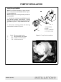
PUMP KIT INSTALLATION
Install Pump Kit #9504
NOTE: For complete information on pump kit installation, consult the Woods BH9000 backhoe operators manual #38638.
0
NOTE: Discard pump mounting bracket provided in
pump kit #9504.
1. Attach pump mounting bracket #54084 supplied
with sub-frame mounting kit #1001378, to pump
assembly (2) using cap screw (3) and lock nut (4)
as shown in Figure 11. Torque hardware to 85 lbs.ft.
2. Attach pump mounting bracket with bent leg
toward tractor as shown in Figure 12.
1.
2.
3.
4.
54084
-----3379
765
Pump mounting bracket
Pump assembly with adapter
1/2 NC x 1-1/2 Cap screw
1/2 NC Hex lock nut
3XPS EUDFNHW
3XPS
µ [ µ %ROW
µ +H[ ORFNQXW
Figure 11 Pump Bracket Installation
Figure 12 Pump and Bracket Installed
MAN0047 (9/15/00)
INSTALLATION 9
PUMP KIT INSTALLATION Cont.
Connect Hydraulic System
WARNING
n Keep hands and body away from pressurized
lines. Use paper or cardboard, not hands or other
body parts to check for leaks. Wear safety goggles.
Hydraulic fluid under pressure can easily penetrate
skin and will cause serious injury or death.
n Make sure that all operating and service personnel know that if hydraulic fluid penetrates skin, it
must be surgically removed as soon as possible by
a doctor familiar with this form of injury or gangrene, serious injury, or death will result. CONTACT
A PHYSICIAN IMMEDIATELY IF FLUID ENTERS SKIN
OR EYES. DO NOT DELAY.
n Make sure all hydraulic hoses, fittings, and
valves are in good condition and not leaking before
starting power unit or using equipment. Check and
route hoses carefully to prevent damage. Hoses
must not be twisted, bent sharply, kinked, frayed,
pinched, or come into contact with any moving
parts. Operate moveable components through full
operational range to check clearances. Replace any
damaged hoses immediately.
10 INSTALLATION
1. Couple the backhoe hydraulic pump to the tractor PTO, if equipped.
2. Insert the pump bracket between the tractor
drawbar support to prevent pump rotation. Engage
the pump PTO coupler pin firmly in the tractor PTO
spline groove.
3. Check all hydraulic fittings and lines to be sure
they are tight and free of kinks or twists.
4. Make sure backhoe {PTO driven hydraulic system is full (approximately 10 US gallons). Check the
tractor hydraulic reservoir and service if necessary.
NOTE: See the BH9000 backhoe operator manual
for hydraulic oil recommendations. Do not mix
hydraulic fluid types.
5. Be sure the backhoe controls are centered in
the neutral position and the backhoe hydraulic
pump is securely mounted to the tractor.
6. With the tractor PTO and transmission in neutral, start the engine and run at low idle.
7. Smoothly engage the PTO pump to provide
backhoe hydraulics.
NOTE: Very little engine power is required to operate the hydraulic system in this mode. Should the
engine pull down excessively, check the plumbing
hook-up for reversed lines or a control lever stuck in
an operating position.
MAN0047 (9/15/00)
SUB-FRAME & BACKHOE INSTALLATION TO TRACTOR
Mount Sub-Frame & Backhoe to Tractor
DANGER
n The sub-frame mount is designed to provide
secure mounting and adequate operator clearance
when properly installed. Check clearance dimensions shown in figure 1 to be sure you have installed
sub-frame correctly. Follow all mounting instructions in this manual. Do not operate backhoe unless
there is adequate clearance. Failure to check and
comply with these instructions may result in serious
injury or death.
n The only time the backhoe may be operated from
a position other than the operator seat is during
backhoe attachment and removal. Operator must
• Read Operator's Manual instructions on
atta ch ing an d r e mov ing ba ck hoe a nd us e
extreme care
• Engage swing lock to prevent boom rotation
• Always stand rearward of backhoe stabilizer
arms or along side of tractor to avoid being
trapped should the boom swing control be accidentally activated.
WARNING
WARNING
n Remove seat and upper support assembly before
installing or removing backhoe from tractor. Failure
to comply may result in equipment failure and/or
personal injury.
1. Remove the backhoe seat assembly.
2. Place sub-frame flat on a hard level surface.
3. Back tractor over the sub-frame and center
between the tractor rear tires. Position tractor so
that the hydraulic system can be connected
4. Use the backhoe hydraulics to maneuver the
sub-frame into position for hook-up. Use care in this
procedure to avoid being trapped between tractor
and backhoe or between backhoe parts.
5. Raise sub-frame up by lowering stabilizers and
boom section until cross tube is level with rear
mounting bracket channel.
6. Shut off tractor. Roll tractor back so tube slides
into channel.
7. Fasten sub-frame in place by placing clevis pins
into channel holes and secure with safety pins.
8. With the tractor engine off, relieve pressure in
the backhoe boom to raise sub-frame into front
hanger.
9. Install bent pin and klik pin.
MAN0047 (9/15/00)
INSTALLATION 11
SUB-FRAME & BACKHOE to TRACTOR Cont.
Attach Top Link
1. Assemble inner top link (2), 1” hex nut (1), and
outer top link (3).
2. Attach top link (inner link end) to backhoe mainframe with 1.0 x 4.5 clevis pin (4) and klik pins (5)
as shown in Figure 14.
3. Adjust top link as necessary to fit between the
backhoe mainframe and tractor top link bracket.
4. Attach outer link end to tractor top link bracket
using original tractor top link pin as shown in Figure
15.
5. Tighten 1” hex nut (1).
Figure 14 Top Link to Backhoe Installation
1.
3132
2.
38645
3. 1001579
4.
45087
5.
62043
6.
-------7.
--------
1” Hex nut
Inner Top Link
Outer Top Link
1.0 x 4.5 Clevis Pin
1/4 x 1-3/4 Klik Pin
Tractor Klik Pin
Tractor Top Link Pin
$WWDFK WR
WUDFWRU
Figure 15 Top Link to Tractor Installation
(Typical Installation)
$WWDFK WR
EDFNKRH
Figure 13 Top Link Assembly
12 INSTALLATION
MAN0047 (9/15/00)
SUB-FRAME & BACKHOE to TRACTOR Cont.
Remove Backhoe With Sub-Frame
DANGER
n The only time the backhoe may be operated from
a position other than the operator seat is during
backhoe attachment and removal. Operator must
• Read Operator's Manual instructions on
atta ch ing an d r e mov ing ba ck hoe a nd us e
extreme care
• Engage swing lock to prevent boom rotation
• Always stand rearward of backhoe stabilizer
arms or along side of tractor to avoid being
trapped should the boom swing control be accidentally activated.
WARNING
WARNING
n Remove seat and upper support assembly before
installing or removing backhoe from tractor. Failure
to comply may result in equipment failure and/or
personal injury.
1. On a hard level surface, center the backhoe
boom.
2. Extend boom and dipperstick so that dipperstick
is perpendicular the bucket all the way towards the
operator (90°) to the ground.
3. Rest bucket on the ground and lower stabilizers
to take backhoe weight off tractor.
4. Turn off engine, set brakes, and remove key
before leaving tractor seat.
5. Remove the seat assembly.
6. Remove top link pins and top link assembly.
7. Remove retaining pins from front sub-frame
bracket and clevis pins from rear hanger bracket.
8. Roll the tractor far enough to release the subframe from the brackets.
9. Start engine and raise the rear of the backhoe
with stabilizers to pivot the front of the sub-frame
down.
10. Place blocks under backhoe mainframe and
raise stabilizers to lower backhoe onto the blocks.
NOTE: The front of the sub-frame must be low
enough to clear the tractor chassis for removal.
11. Turn off engine, set brakes, and remove key
before leaving tractor seat.
12. Disengage the tractor PTO and remove the
backhoe hydraulic pump from the PTO shaft, if
equipped, or disengage the tractor hydraulic circuit
and disconnect the hydraulic quick couplers.
13. Make sure backhoe and sub-frame clear the
tractor chassis and drive the tractor away.
MAN0047 (9/15/00)
INSTALLATION 13
SUB-FRAME & BACKHOE to TRACTOR Cont.
Store Hydraulic Pump
1. Disconnect pump (1) from tractor PTO.
2. Rotate pump and insert pin on pump mounting
bracket through outside hole on foot rest as shown
in Figure 16.
3. Secure to foot rest (3) with klik pin (2).
Figure 16 Hydraulic Pump Storage
NOTES
14 INSTALLATION
MAN0047 (9/15/00)
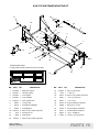
#1001378 SUB-FRAME MOUNTING KIT
21
34
6
35
25
29
5
33
32
30
27
2
22
23
7
CD5739
30
24
4
8
1
20
3
34
26
26
24
30
Serial Number Plate
26
Located inside sub-frame side rail, rear of cross tube
02'(/ 12
6(5,$/ 12
,' 12
<5 2) 0)*
34
31
0$66 .*
25(*21 ,/ 86$
REF
PART
QTY
1
1001380
1
Right rear support
24
307825
5
M14 x 2.0P Hex nut
2
1001381
1
Left rear support
25
3132
1
1” Hex nut
3
1001383
1
Front support
26
33125 10 M14 x 2.0P x 50mm Cap screw
4
1001387
1
Cross member
27
37827
1
.75 x 3.14 Clevis pin
5
1001579
1
Outer top link 18.5”
29
45087
1
1.0 x 4.5 Pin
6
38645
1
Inner top link
30
46070 22 9/16 Flat washer, hardened
7
46976
1
Sub-frame for BH9000
31
54088
1
Bent pin.75 x 19.36
8
54084
1
Pump Bracket
32
57798
6
3/4 Flat washer, hardened
20
1001575
6
M14 x 2.0P x 55mm Cap screw
33
57817
4
5/8 flat washer, hardened
21
1450
6
3/4 NC Hex nut
34
62043
4
1/4 x 1-3/4 Klik pin
22
2688
2
5/32 Hair pin
35
13759
6
3/4 NC x 2-1/4 Cap screw
23
307434
4
M16 x 2.0P x 45mm Cap screw
(Rev. 11/22/00)
MAN0047 (9/15/00)
DESCRIPTION
REF
PART
QTY
DESCRIPTION
PARTS 15
BOLT TORQUE CHART
Always tighten hardware to these values unless a different torque value or tightening procedure is listed for a specific
application.
Fasteners must always be replaced with the same grade as specified in the manual parts list.
Always use the proper tool for tightening hardware: SAE for SAE hardware and Metric for metric hardware.
Make sure fastener threads are clean and you start thread engagement properly.
All torque values are given to specifications used on hardware defined by SAE J1701 & J1701M JUL96.
SAE Bolt Head
Identification
SAE SERIES
TORQUE
CHART
A
SAE Grade 2
(No Dashes)
SAE Grade 8
(6 Radial Dashes)
SAE Grade 5
(3 Radial Dashes)
MARKING ON HEAD
A
SAE 2
SAE 5
SAE 8
Diameter
(Inches)
Wrench
Size
Lbs.-Ft.
N-m
Lbs.-Ft.
N-m
Lbs.-Ft.
N-m
1/4”
7/16”
6
8
10
13
14
18
5/16”
3/8”
1/2”
9/16”
12
23
17
31
19
35
26
47
27
49
37
67
7/16”
1/2”
5/8”
3/4”
36
55
48
75
55
85
75
115
78
120
106
163
9/16”
5/8”
13/16”
15/16”
78
110
106
149
121
170
164
230
171
240
232
325
3/4”
7/8”
1-1/8”
1-15/16”
192
306
261
416
297
474
403
642
420
669
569
907
1”
1-1/2”
467
634
722
979
1020
1383
A
METRIC SERIES
TORQUE
CHART
A
Metric Bolt Head
Identification
8.8
Metric
Grade 8.8
10.9
Metric
Grade 10.9
COARSE THREAD
FINE THREAD
MARKING ON HEAD
MARKING ON HEAD
A
Diameter &
Thread Pitch
(Millimeters)
Wrench
Size
N-m
Lbs.-Ft.
N-m
Lbs.-Ft.
N-m
Lbs.-Ft.
N-m
Lbs.-Ft.
Diameter &
Thread Pitch
(Millimeters)
6 x 1.0
8 x 1.25
10 mm
13 mm
8
20
6
15
11
27
8
20
8
21
6
16
11
29
8
22
6 x 1.0
8 x 1.0
10 x 1.5
12 x 1.75
16 mm
18 mm
39
68
29
50
54
94
40
70
41
75
30
55
57
103
42
76
10 x 1.25
12 x 1.25
14 x 2.0
16 x 2.0
21 mm
24 mm
109
169
80
125
151
234
111
173
118
181
87
133
163
250
120
184
14 x 1.5
16 x 1.5
18 x 2.5
20 x 2.5
27 mm
30 mm
234
330
172
244
323
457
239
337
263
367
194
270
363
507
268
374
18 x 1.5
20 x 1.5
22 x 2.5
24 x 3.0
34 mm
36 mm
451
571
332
421
623
790
460
583
495
623
365
459
684
861
505
635
22 x 1.5
24 x 2.0
30 x 3.0
46 mm
1175
867
1626
1199
1258
928
1740
1283
30 x 2.0
Metric 8.8
Typical Washer Installations
Lockwasher
Metric 10.9
Metric 8.8
Metric 10.9
Flat Washer
Bolt
Nut
16 APPENDIX
8/9/00
Bolt Torque & Size Charts (Rev. 9/5/00)
BOLT SIZE CHART
NOTE: Chart shows bolt thread sizes and corresponding head (wrench) sizes for standard SAE and metric bolts.
SAE Bolt Thread Sizes
5/16
IN
MM
3/8
1/2
5/8
3/4
7/8
1
2
3
4
5
6
7
25
50
75
100
125
150
175
Metric Bolt Thread Sizes
8MM
10MM
12MM
14MM
16MM
18MM
ABBREVIATIONS
AG............................................................. Agriculture
NC ....................................................National Coarse
ATF .............................. Automatic Transmission Fluid
NF ......................................................... National Fine
BSPP ........................... British Standard Pipe Parallel
NPSM ...................National Pipe Straight Mechanical
BSPTM .............. British Standard Pipe Tapered Male
NPT ........................................ National Pipe Tapered
CV................................................... Constant Velocity
NPT SWF........ National Pipe Tapered Swivel Female
CCW ............................................ Counter-Clockwise
ORBM ......................................... O-Ring Boss - Male
CW............................................................. Clockwise
P .........................................................................Pitch
F .....................................................................Female
PBY .....................................................Power Beyond
GA ...................................................................Gauge
psi ........................................ Pounds per Square Inch
GR (5, etc.) ......................................... Grade (5, etc.)
PTO ................................................... Power Take Off
HHCS ...................................... Hex Head Cap Screw
QD ..................................................Quick Disconnect
HT .......................................................... Heat Treated
RH ............................................................Right Hand
JIC ...............Joint Industry Council 37° Degree Flare
ROPS.......................... Roll Over Protective Structure
LH ............................................................... Left Hand
RPM.......................................Revolutions Per Minute
LT .........................................................................Left
RT ...................................................................... Right
m....................................................................... Meter
SAE ........................Society of Automotive Engineers
mm.............................................................. Millimeter
UNC ....................................................Unified Coarse
M.........................................................................Male
UNF ........................................................ Unified Fine
MPa ....................................................... Mega Pascal
UNS ....................................................Unified Special
N .................................................................... Newton
Bolt Torque & Size Charts (Rev. 9/5/00)
APPENDIX 17
WARRANTY
(Replacement Parts For All Models Except Mow’n Machines)
WEC Company, d/b/a Woods Equipment Company (“WOODS”), warrants this product to be free from
defect in material and workmanship for a period of ninety (90) days from the date of delivery of the product to the original purchaser.
Under no circumstances will this Warranty apply in the event that the product, in the good faith opinion of
WOODS, has been subjected to improper operation, improper maintenance, misuse, or an accident. This
Warranty does not cover normal wear or tear, or normal maintenance items.
This Warranty is extended solely to the original purchaser of the product. Should the original purchaser
sell or otherwise transfer this product to a third party, this Warranty does not transfer to the third party purchaser in any way. There are no third party beneficiaries of this Warranty.
WOODS’ obligation under this Warranty is limited to, at WOODS’ option, the repair or replacement, free
of charge, of the product if WOODS, in its sole discretion, deems it to be defective or in noncompliance
with this Warranty. The product must be returned to WOODS with proof of purchase within thirty (30)
days after such defect or noncompliance is discovered or should have been discovered, routed through the
dealer and distributor from whom the purchase was made, transportation charges prepaid. WOODS shall
complete such repair or replacement within a reasonable time after WOODS receives the product. THERE
ARE NO OTHER REMEDIES UNDER THIS WARRANTY. THE REMEDY OF REPAIR OR
REPLACEMENT IS THE SOLE AND EXCLUSIVE REMEDY UNDER THIS WARRANTY.
THERE ARE NO WARRANTIES WHICH EXTEND BEYOND THE DESCRIPTION ON THE FACE
OF THIS WARRANTY. WOODS MAKES NO OTHER WARRANTY, EXPRESS OR IMPLIED, AND
WOODS SPECIFICALLY DISCLAIMS ANY IMPLIED WARRANTY OF MERCHANTABILITY
AND/OR ANY IMPLIED WARRANTY OF FITNESS FOR A PARTICULAR PURPOSE.
WOODS shall not be liable for any incidental or consequential losses, damages or expenses, arising
directly or indirectly from the product, whether such claim is based upon breach of contract, breach
of warranty, negligence, strict liability in tort or any other legal theory. Without limiting the generality
of the foregoing, Woods specifically disclaims any damages relating to (i) lost profits, business, revenues
or goodwill; (ii) loss of crops; (iii) loss because of delay in harvesting; (iv) any expense or loss incurred for
labor, supplies, substitute machinery or rental; or (v) any other type of damage to property or economic
loss.
This Warranty is subject to any existing conditions of supply which may directly affect WOODS’ ability to
obtain materials or manufacture replacement parts.
No agent, representative, dealer, distributor, service person, salesperson, or employee of any company,
including without limitation, WOODS, its authorized dealers, distributors, and service centers, is authorized to alter, modify, or enlarge this Warranty.
Answers to any questions regarding warranty service and locations may be obtained by contacting:
Woods Equipment
Company
2606 Illinois Route 2 South
Post Office Box 1000
Oregon, Illinois 61061
815-732-2141 tel
815-732-7580 fax
F-8494 Effective 3/1/2000
y
WARRANTY
(All Models Except Mow’n Machines)
Please Enter Information Below and Save For Future Reference.
Date Purchased: __________________________
From (Dealer): _____________________________
Model Number: __________________________
Serial Number: _____________________________
WEC Company, d/b/a Woods Equipment Company (“WOODS”), warrants this product to be free from defect in material
and workmanship. Except as otherwise set forth below, the duration of this Warranty shall be for TWELVE (12) MONTHS
COMMENCING ON THE DATE OF DELIVERY OF THE PRODUCT TO THE ORIGINAL PURCHASER.
The warranty period for certain gearboxes are listed below:
Model No.
1160, 1190, BB600, BB720, BB840, BB6000,
BB7200, BB8400
1130, 3180, 3240, BB48, BB60, BB72, BB84
Part Warranted
Duration
Gearbox components
Gearbox components
XT148, XT160, XT172, XT184
Rotary cutter gearbox
5 years from the date of delivery.
3 years from the date of delivery.
90 days from the date of delivery if used
in rental or commercial applications.
Under no circumstances will this Warranty apply in the event that the product, in the good faith opinion of WOODS, has been
subjected to improper operation, improper maintenance, misuse, or an accident. This Warranty does not apply in the event that
the product has been materially modified or repaired by someone other than WOODS, a WOODS authorized dealer or distributor, and/or a WOODS authorized service center. This Warranty does not cover normal wear or tear, or normal maintenance
items. This Warranty also does not cover repairs made with parts other than those obtainable through WOODS.
This Warranty is extended solely to the original purchaser of the product. Should the original purchaser sell or otherwise transfer this product to a third party, this Warranty does not transfer to the third party purchaser in any way. There are no third party
beneficiaries of this Warranty.
WOODS makes no warranty, express or implied, with respect to engines, batteries, tires or other parts or accessories not manufactured by WOODS. Warranties for these items, if any, are provided separately by their respective manufacturers.
WOODS’ obligation under this Warranty is limited to, at WOODS’ option, the repair or replacement, free of charge, of the
product if WOODS, in its sole discretion, deems it to be defective or in noncompliance with this Warranty. The product must
be returned to WOODS with proof of purchase within thirty (30) days after such defect or noncompliance is discovered or
should have been discovered, routed through the dealer and distributor from whom the purchase was made, transportation
charges prepaid. WOODS shall complete such repair or replacement within a reasonable time after WOODS receives the
product. THERE ARE NO OTHER REMEDIES UNDER THIS WARRANTY. THE REMEDY OF REPAIR OR REPLACEMENT IS THE SOLE AND EXCLUSIVE REMEDY UNDER THIS WARRANTY.
THERE ARE NO WARRANTIES WHICH EXTEND BEYOND THE DESCRIPTION ON THE FACE OF THIS WARRANTY. WOODS MAKES NO OTHER WARRANTY, EXPRESS OR IMPLIED, AND WOODS SPECIFICALLY DISCLAIMS ANY IMPLIED WARRANTY OF MERCHANTABILITY AND/OR ANY IMPLIED WARRANTY OF FITNESS
FOR A PARTICULAR PURPOSE.
WOODS shall not be liable for any incidental or consequential losses, damages or expenses, arising directly or indirectly from the product, whether such claim is based upon breach of contract, breach of warranty, negligence, strict
liability in tort or any other legal theory. Without limiting the generality of the foregoing, Woods specifically disclaims any
damages relating to (i) lost profits, business, revenues or goodwill; (ii) loss of crops; (iii) loss because of delay in harvesting;
(iv) any expense or loss incurred for labor, supplies, substitute machinery or rental; or (v) any other type of damage to property
or economic loss.
This Warranty is subject to any existing conditions of supply which may directly affect WOODS’ ability to obtain materials or
manufacture replacement parts.
No agent, representative, dealer, distributor, serviceperson, salesperson, or employee of any company, including without limitation, WOODS, its authorized dealers, distributors, and service centers, is authorized to alter, modify, or enlarge this Warranty.
This Warranty is effective only if the warranty registration card is returned within ten (10) days.
Answers to any questions regarding warranty service and locations may be obtained by contacting:
Woods Equipment
Company
2606 Illinois Route 2 South
Post Office Box 1000
Oregon, Illinois 61061
815-732-2141 tel
815-732-7580 fax
F-3079 Effective 3/2/2000 (Revised 10/12/2000)
PART NO.
MAN0047
Woods Equipment
Company
2606 Illinois Route 2 South
Post Office Box 1000
Oregon, Illinois 61061
815-732-2141 tel
815-732-7580 fax