1
111868 LOADER MOUNTING KIT
Loaders
1020
1027
Includes
Valve Kits
56037
56038
56042
Hose Kits
40542
40547
46047
46018
PN-46018 (Rev. 3/15/02)
mounting to
Kubota Tractor Models
M8200
M9000
TO THE DEALER:
Assembly and proper installation of this product is the responsibility of the WOODS dealer. Read manual instructions
and safety rules. Make sure all items on the Dealer’s Pre-Delivery and Delivery Check Lists in the Operator’s Manual
are completed before releasing equipment to the owner.
TO THE OWNER:
Read this manual before operating your WOODS equipment. The information presented will prepare you to do a better
and safer job. Keep this manual handy for ready reference. Require all operators to read this manual carefully and
become acquainted with all the adjustment and operating procedures before attempting to operate. Replacement
manuals can be obtained from your dealer or, in the United States and Canada, by calling 1-800-319-6637.
The equipment you have purchased has been carefully engineered and manufactured to provide dependable and
satisfactory use. Like all mechanical products, it will require cleaning and upkeep. Lubricate the unit as specified.
Observe all safety information in this manual and safety decals on the equipment.
For service, your authorized WOODS dealer has trained mechanics, genuine WOODS service parts, and the
necessary tools and equipment to handle all your needs.
Use only genuine WOODS service parts. Substitute parts will void the warranty and may not meet standards required
for safe and satisfactory operation. Record the model number and serial number of your equipment in the spaces
provided:
Model: 111868 Loader Mounting Kit
Provide this information to your dealer to obtain correct repair parts.
Throughout this manual, the term IMPORTANT is used to indicate that failure to observe can cause damage to
equipment. The terms CAUTION, WARNING and DANGER are used in conjunction with the Safety-Alert Symbol, (a
triangle with an exclamation mark), to indicate the degree of hazard for items of personal safety.
This Safety-Alert Symbol indicates a hazard and means
ATTENTION! BECOME ALERT! YOUR SAFETY IS INVOLVED!
Indicates an imminently hazardous situation that, if not avoided, will
result in death or serious injury.
Indicates a potentially hazardous situation that, if not avoided,
could result in death or serious injury, and includes hazards that are
exposed when guards are removed.
Indicates a potentially hazardous situation that, if not avoided, may
result in minor or moderate injury.
Indicates that failure to observe can cause damage to equipment.
NOTE
ii
Indicates helpful information.
Introduction (2/9/01)
SAFETY RULES
ATTENTION! BECOME ALERT! YOUR SAFETY IS INVOLVED!
Safety is a primary concern in the design and
manufacture of our products. Unfortunately, our
efforts to provide safe equipment can be wiped out
by an operator’s single careless act.
In addition to the design and configuration of
equipment, hazard control and accident prevention are dependent upon the awareness, concern,
judgement, and proper training of personnel
involved in the operation, transport, maintenance
and storage of equipment.
It has been said “The best safety device is an
informed, careful operator.” We ask you to be that
kind of operator.
INSTALLATION
During installation, the tractor engine should be
off, the key removed and the brakes locked. Do not
disconnect hydraulic lines until attachments are
removed or lowered to the ground and system
pressure is released by operating valve levers.
Never operate any hydraulic cylinders during any
phase of the installation process.
This Loader Mounting Kit is to be used only for
the loaders and tractors specified in the Loader
Mount Installation section of this manual. Any
other use or modification of this mounting kit may
result in serious injury or death.
Hydraulics must be connected as instructed in
this manual. Do not substitute parts, modify, or
connect in any other way.
After connecting hoses, check that all control
lever positions function as instructed in the Operator’s Manual. Do not put into service until control
lever and equipment movements are correct.
TRAINING
Safety instructions are important! Read all
attachment and power unit manuals; follow all
safety rules and safety decal information. (Replacement manuals are available from dealer or, in the
United States and Canada, call 1-800-319-6637.)
Failure to follow instructions or safety rules can
result in serious injury or death.
If you do not understand any part of this manual
and need assistance, see your dealer.
Loader Mounting Kit (9/11/00)
Know your controls and how to stop engine and
attachment quickly in an emergency.
Keep hands and body away from pressurized
lines. Use paper or cardboard, not hands or other
body parts to check for leaks. Wear safety goggles.
Hydraulic fluid under pressure can easily penetrate
skin and will cause serious injury or death.
Make sure that all operating and service personnel know that if hydraulic fluid penetrates skin, it
must be surgically removed as soon as possible by
a doctor familiar with this form of injury or gangrene, serious injury, or death will result. CONTACT A P HYS ICIA N IM ME DIATE LY IF FLU ID
ENTERS SKIN OR EYES. DO NOT DELAY.
Never allow children or untrained persons to
operate equipment.
PREPARATION
Check that all hardware is properly installed.
Always tighten to torque chart specifications
unless instructed otherwise in this manual.
Air in hydraulic systems can cause erratic operation and allows loads or equipment components
to drop unexpectedly. When connecting equipment
or hoses or performing any hydraulic maintenance,
purge any air in hydraulic system by operating all
hydraulic functions several times. Do this before
p ut t i ng i n t o s e r v i c e o r a l l o w i n g a n y o n e t o
approach the equipment.
After connecting hoses, check that all control
lever positions function as instructed in the Operator’s Manual. Do not put into service until control
lever and equipment movements are correct.
Protective hose sleeves must cover all hydraulic hoses and be secured onto metal hose fittings.
Replace hoses or sleeves if damaged or if protective sleeve cannot be properly positioned or
secured.
Make sure all hydraulic hoses, fittings, and
valves are in good condition and not leaking before
starting power unit or using equipment. Check and
route hoses carefully to prevent damage. Hoses
must not be twisted, bent sharply, kinked, frayed,
pinched, or come into contact with any moving
parts. Operate moveable components through full
operational range to check clearances. Replace
any damaged hoses immediately.
(Safety Rules continued on next page)
SAFETY 1
SAFETY RULES
ATTENTION! BECOME ALERT! YOUR SAFETY IS INVOLVED!
(Safety Rules continued from previous page)
Do not connect a low-pressure hydraulic hose
into a high-pressure system—it will burst the hose.
Do not use a high-pressure hose in place of a lowpressure hose—it is possible to rupture the valve.
Always wear relatively tight and belted clothing
to avoid entanglement in moving parts. Wear
sturdy, rough-soled work shoes and protective
equipment for eyes, hair, hands, hearing, and head.
Make sure attachment is properly secured,
adjusted, and in good operating condition.
Power unit must be equipped with ROPS or
ROPS cab and seat belt. Keep seat belt securely
fastened. Falling off power unit can result in death
from being run over or crushed. Keep foldable
ROPS systems in “locked up” position at all times.
Whenever 3-point implements are attached to
tractor, always check full range of operation for
mechanical or hydraulic hose interference.
Make sure all safety decals are installed.
Replace if damaged. (See Safety Decals section for
location.)
Make sure shields and guards are properly
installed and in good condition. Replace if damaged.
OPERATION
Do not allow bystanders in the area when operating, attaching, removing, assembling, or servicing equipment.
Keep bystanders away from equipment.
Do not operate or transport equipment while
under the influence of alcohol or drugs.
Always comply with all state and local lighting
and marking requirements.
Never allow riders. Do not lift or carry anybody
on the loader or in the bucket or attachments.
Power unit must be equipped with ROPS or
ROPS cab and seat belt. Keep seat belt securely
fastened. Falling off power unit can result in death
from being run over or crushed. Keep foldable
ROPS systems in “locked up” position at all times.
Always sit in power unit seat when operating
controls or starting engine. Securely fasten seat
belt, place transmission in neutral, engage brake,
and ensure all other controls are disengaged
before starting power unit engine.
2 SAFETY
Before dismounting power unit or performing
any service or maintenance, follow these steps:
disengage power to equipment, lower the 3-point
hitch and all raised components to the ground,
operate valve levers to release any hydraulic pressure, set parking brake, stop engine, remove key,
and unfasten seat belt.
Never work under a raised loader. Always lower
loader to the ground with bucket or loader attachment in full roll-back position. Shut off tractor, set
parking brake, and remove key. Operate valve
levers to release any hydraulic pressure. If loader
obstructs tractor maintenance, loader must be
removed from tractor.
MAINTENANCE
Before dismounting power unit or performing
any service or maintenance, follow these steps:
disengage power to equipment, lower the 3-point
hitch and all raised components to the ground,
operate valve levers to release any hydraulic pressure, set parking brake, stop engine, remove key,
and unfasten seat belt.
Never work under a raised loader. Always lower
loader to the ground with bucket or loader attachment in full roll-back position. Shut off tractor, set
parking brake, and remove key. Operate valve
levers to release any hydraulic pressure. If loader
obstructs tractor maintenance, loader must be
removed from tractor.
Refer to loader manual and follow all maintenance safety rules and instructions.
Do not modify or alter or permit anyone else to
modify or alter the equipment or any of its components in any way.
Your dealer can supply original equipment
hydraulic accessories and repair parts. Substitute
parts may not meet original equipment specifications and may be dangerous.
Always wear relatively tight and belted clothing
to avoid entanglement in moving parts. Wear
sturdy, rough-soled work shoes and protective
equipment for eyes, hair, hands, hearing, and head.
Do not allow bystanders in the area when operating, attaching, removing, assembling, or servicing equipment.
Make sure attachment is properly secured,
adjusted, and in good operating condition.
Loader Mounting Kit (9/11/00)
SAFETY RULES
ATTENTION! BECOME ALERT! YOUR SAFETY IS INVOLVED!
Keep all persons away from operator control
area while performing adjustments, service, or
maintenance.
Make sure shields and guards are properly
installed and in good condition. Replace if damaged.
Tighten all bolts, nuts and screws to torque
chart specifications. Check that all cotter pins are
installed securely to ensure equipment is in a safe
condition before putting unit into service.
Do not disconnect hydraulic lines until all system pressure is relieved. Lower unit to ground,
stop engine, and operate all hydraulic control
levers.
Make sure all safety decals are installed.
Replace if damaged. (See Safety Decals section for
location.)
Loader Mounting Kit (9/11/00)
SAFETY 3
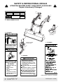
SAFETY & INSTRUCTIONAL DECALS
ATTENTION! BECOME ALERT! YOUR SAFETY IS INVOLVED!
Replace Immediately If Damaged!
MODEL NO.
SERIAL NO.
ID NO.
6
5
MASS (KG)
1
2
YR OF MFG.
OREGON, IL U.S.A.
3
4 - SERIAL NUMBER PLATE
4
9
7
11
2 - PN 56053
Loader Mount
(Left Side)
DANGER
8
Optional Loader
Control Valve
Serious injury or death
can result from contact
with electrical lines.
1 - PN 56052
WARNING
10
DANGER
FALLING LOAD
HAZARD
3 - PN 56051
WARNING
n Read and understand Operator’s
ROLLOVERS CAN
RESULT IN INJURY
OR DEATH
n
n
n
n
n
n
Always use ROPS and
seat belt.
Add rear tractor
ballast.
Move wheels to widest
setting.
Avoid slope operation.
Operate at low speeds.
Carry load low.
56053-A
4 SAFETY
n
n
n
n
Manual before operating.
(Replacement manuals are
available from dealer or, in the
United States and Canada, call
1-800-319-6637.)
Keep others away when operating
loader.
Do not allow children or untrained
persons to operate equipment.
Lower loader to ground, stop engine, set park brake and remove
key before leaving tractor seat.
Failure to follow safety rules can
result in serious injury or death.
56051-A
To avoid injury
or death
Do not handle round
bale or other shiftable
load unless loader is
equipped with
approved attachments.
(Read Operators
Manual.)
n Lift and carry only one
bale at a time.
n Handle raised load with
caution.
n Carry load low. 56052-A
n
(Safety Decals continued on next page)
PN-46018 (Rev. 11/10/00)
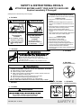
SAFETY & INSTRUCTIONAL DECALS
ATTENTION! BECOME ALERT! YOUR SAFETY IS INVOLVED!
Replace Immediately If Damaged!
(Safety Decals continued from previous page)
LOADER MOUNTING INSTRUCTIONS
6 - PN 56050
WARNING
WARNING
CRUSHING HAZARD
To avoid injury
or death:
n Do not walk or work underneath a raised loader.
n Lower loader to ground
before leaving tractor
seat.
FALLING HAZARD
To avoid injury
or death:
n Do not work from or
allow riders on loader or
its attachments.
56050-A
5 - PN 19924
Read Operator’s Manual instructions before proceding.
To Remove Loader
1. Park tractor on level surface with bucket flat on
ground.
2. Dump bucket to take weight off mount pins and
allow for stand installation. Set brake and shut off
tractor.
3. Remove stands from crosstube and pin into brackets.
(Pin location noted in mounting manual.)
4. Remove mount pins from loader upright.
5. Roll back bucket completely to raise uprights from
mounts.
6. Shut off engine. Disconnect hydraulics. Back tractor
away. Store mount pins in loader uprights.
To Mount Loader
Remove mount pins from uprights.
Drive tractor into loader slowly.
Shut off tractor. Connect hydraulics.
Dump bucket to lower upright into mounts.
Continue dumping bucket until uprights settle into
mounts, pins can be installed and stands can be
removed. Set brake and shut off tractor.
6. Install mount pins and clips. Remove stands and pin
into crosstube.
56059-A
1.
2.
3.
4.
5.
9 - PN 56059
WARNING
HIGH-PRESSURE HYDRAULIC OIL LEAKS CAN PENETRATE SKIN
RESULTING IN SERIOUS INJURY, GANGRENE OR DEATH.
n Check for leaks with cardboard; never use hand.
n Before loosening fittings: lower load, release pressure, and
be sure oil is cool.
19924-B
n Consult physician immediately if skin penetration occurs.
8 - PN 45002
(WHEN EQUIPPED)
WARNING
LOADER ATTACHMENT CAN FALL OFF IF NOT PROPERLY ATTACHED.
n Read operator’s manuals for instructions.
n Position and align loader to attachment.
n Rotate coupler handles to full locked position. Lockpins must fully extend and
engage into attachment retaining slots.
n Attachment mechanism must be functional and in good repair.
n Only use loader manufacturer approved attachments.
n For information on approved attachments, call 1-800-319-6637.
Failure to follow these instructions can result in serious injury or death. 56055-B
"#
10 - PN 56889
(WHEN EQUIPPED)
7 - PN 56055
8 - PN 260274
(WHEN EQUIPPED)
11 - PN 45024
WARNING
LOADER ATTACHMENT CAN FALL OFF IF NOT PROPERLY ATTACHED.
Only use loader manufacturer approved attachments.
Failure to do so can cause serious injury or death.
PN-46018 (Rev. 11/10/00)
45024-A
AUXILIARY
CONTROL
56889
LOADER
CONTROL
260274-C
SAFETY 5
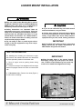
LOADER MOUNT INSTALLATION
WARNING
■ Only use 111868 Loader Mounting Kit for mount-
ing Woods 1020/1027 loaders to Kubota M8200 and
M9000 tractors. Any other use or modification of
this kit may result in serious injury or death.
CAUTION
Safety instructions are important! Read all
attachment and power unit manuals; follow all
safety rules and safety decal information. (Replacement manuals are available from dealer or, in the
United States and Canada, call 1-800-319-6637.)
Failure to follow instructions or safety rules can
result in serious injury or death.
If you do not understand any part of this manual
and need assistance, see your dealer.
Do not modify or alter or permit anyone else to
modify or alter the equipment or any of its components in any way.
IMPORTANT
Always wear relatively tight and belted clothing
to avoid entanglement in moving parts. Wear
sturdy, rough-soled work shoes and protective
equipment for eyes, hair, hands, hearing, and head.
■ A front wheel track setting of 60.6” is the widest
setting allowed by the tractor manufacturer for
2WD models using front end loaders.
TRACTOR PREPARATION
For installing this mounting kit, references to right,
left, forward, and rearward directions are determined
from the operator’s position in the tractor seat.
1. Shut off engine and set parking brake during
installation.
IMPORTANT
■ Clean threaded holes in the tractor chassis
thoroughly, using a tap of the proper size. Paint,
rust, or debris in the threads may not permit cap
screws to be installed and tightened correctly.
2. Remove the tractor front weights and front weight
bracket if equipped. Remove tool box on tractors with
cab.
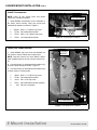
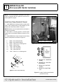
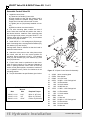
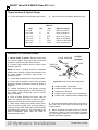
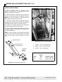
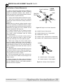
3. Cab tractors only – Remove four bolts (Figure 1)
for cab tractor mountings.
Figure 1 Remove 4 bolts on each side
6 Mount Installation
PN-46018 (Rev. 3/15/02)
LOADER MOUNT INSTALLATION Cont’d
Remove Tractor Connector Tube or
Adapter Block
(1*,1( (1'
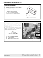
Follow this procedure only if using #40547 or
#46047 Hose Kits.
NOTE: It is easier to remove the connector tube or
adapter block before installing the right mount.
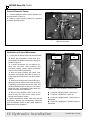
1. Remove tractor hydraulic line connector tube or
adapter block (if equipped) as shown in Figure 2.
2. To prevent the line from leaking during installation
of the loader mounts, be sure to plug the fitting. A 3/4”
plastic cap taken from an adapter in the hose kit may
be used.
/,1(
&$33('
&0
Figure 2 Hydraulic connector Tube Removed
(Rear line capped with 3/4” plastic cap)
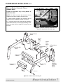
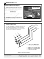
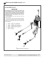
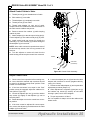
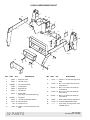
RH Rear Mount
44490
Spacer
Plate
46015
Spacer
Plate
46015
Crossmember
46000
RH Side Rail
59628
LH Rear Mount
44491
Grill Guard
1000545
LH Side Rail
59631
Front Support
1002896
Loader
Mounting
Instruction
Decal
56059
CD5612C-Var
Figure 3 111868 Loader Mounting Kit
PN-46018 (3/15/02)
Mount Installation 7
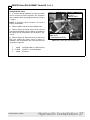
LOADER MOUNT INSTALLATION Cont’d
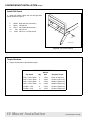
Install Crossmember
NOTE: Leave all cap screws loose until loader
mounts are completely installed.
&52660(0%(5
1. Install #46000 crossmember to the underside of
the tractor clutch housing, using cap screws and
hardened flat washers as shown in Figure 4.
1.
2.
3.
4.
307502
57798
67376
57816
M18 x 1.5 x 85mm Cap screw
3/4 Hardened flat washer
M12 x 1.25 x 80mm Cap screw
1/2 Hardened flat washer
Figure 4 Crossmember Installed
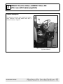
Install Rear Loader Mounts
/2$'(5
02817
1. Install #44490 right rear mount and #44491 left
rear mount to tractor chassis and crossmember.
NOTE: Non-cab tractors will need #46015 spacer
plate installed between the rear mounts and the tractor.
2. Use cap screws (1) and hardened flat washers (2)
at tractor clutch housing as shown in Figure 5.
3. Use cap screws (3) and hardened flat washers (4)
to attach mount to crossmember.
1.
2.
3.
4.
6.
46019
57798
12274
57817
230
M18 x 1.5 x 70mm Cap screw
3/4 Hardened flat washer
5/8 x 2-1/4 Cap screw
5/8 Hardened flat washer (hidden)
5/8 Hex nut (hidden)
&0
&52660(0%(5
Figure 5 Left Rear Mount Installed
8 Mount Installation
PN-46018 (Rev. 3/15/02)
LOADER MOUNT INSTALLATION Cont’d
Install Front Mount Bracket
1. Install front mount bracket (3) to tractor steering
housing, using cap screws (17) and hardened flat
washers (11) as shown in Figure 6.
3
3. 1002896
11. 57817
17. 307425
Front mount bracket
5/8 Hardened flat washer
M16 x 1.5 x 35mm Cap screw
17
11
Figure 6 Front Mount Bracket
Install Side Rails
1. Install #59628 right side rail and #59631 left side
rail to outside of rear mounts as shown in Figure 7.
Secure with cap screws (13), hardened flat washers
(11), and hex nuts (12).
13
11
12
2. Secure at front support with cap screws (13), flat
washers (11), and hex nuts (12). Flat washers are
installed over the slot as shown below.
11.
12.
13.
57817
230
4548
5/8 Hardened flat washer
5/8 Hex nut
5/8 NC x 1-3/4 Cap screw
13
11
&0
/()7
/2$'(5
02817
12
Figure 7 Side Rails Installed to Rear Mounts
& Front Support
PN-46018 (3/15/02)
Mount Installation 9
LOADER MOUNT INSTALLATION Cont’d
Install Grill Guard
1. Install grill guard outside the left and right side
rails as shown in Figure 8.
5.
6.
11.
12.
13.
59628
59631
57817
230
4548
Right side rail (not shown)
Left side rail
5/8 Hardened flat washer
5/8 Hex nut
5/8 NC x 1-3/4 Cap screw
6
12
11
13
CD5612C-Var
Figure 8 Grill Guard Installed
Torque Hardware
1. Tighten all hardware to specifications given.
TORQUE SPECIFICATIONS
Wrench
Qty
Size
Required Torque
M12 x 1.25 x 80mm
Cap Screw
2
18mm
76 lbs.-ft.(103 N-m)
M16 x 1.50 x 35mm
6
24mm
133 lbs.-ft.(181 N-m)
M18 x 1.50 x 85mm
2
27mm
194 lbs.-ft.(263 N-m)
M18 x 1.50 x 70mm
12
27mm
194 lbs.-ft.(263 N-m)
5/8 NC x 1-3/4
8
15/16”
170 lbs.-ft.(230 N-m)
5/8 NC x 2-1/4
12
15/16”
170 lbs.-ft.(230 N-m)
10 Mount Installation
PN-46018 (Rev. 3/15/02)
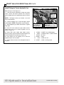
CONTROL VALVE & HOSE KIT INSTALLATION
WARNING
WARNING
WARNING
WARNING
■
Keep hands and body away from pressurized
lines. Use paper or cardboard, not hands or other
body parts to check for leaks. Wear safety goggles.
Hydraulic fluid under pressure can easily penetrate
skin and will cause serious injury or death.
■
Make sure that all operating and service personnel know that if hydraulic fluid penetrates skin,
it must be surgically removed as soon as possible
by a doctor familiar with this form of injury or gangrene, serious injury, or death will result. CONTACT A PHYSICIAN IMMEDIATELY IF FLUID
ENTERS SKIN OR EYES. DO NOT DELAY.
■
Air in hydraulic systems can cause erratic
operation and allow loads or equipment components to drop unexpectedly. When connecting
equipment or hoses or performing any hydraulic
maintenance, purge any air in hydraulic system by
operating all hydraulic functions several times. Do
this before operating or allowing anyone to
approach the equipment.
■
Make sure all hydraulic hoses, fittings, and
valves are in good condition and not leaking before
starting power unit or using equipment. Check and
route hoses carefully to prevent damage. Hoses
must not be twisted, bent sharply, kinked, frayed,
pinched, or come into contact with any moving
parts. Operate moveable components through full
operational range to check clearances. Replace
any damaged hoses immediately.
■
Protective hose sleeves must cover all hydraulic hoses and be secured onto metal hose fittings.
Replace hoses or sleeves if damaged or if protective sleeve cannot be properly positioned or
secured.
IMPORTANT
■
Hydraulic valves must be connected to the
tractor hydraulic system as shown in this loader
mounting kit manual.
■
If hydraulic lines are not connected as shown
in the mounting kit manual, the loader control valve
may be damaged. A blocked outlet (Return) or
improper hose connection will cause pressurized
oil to enter the return circuit and damage the valve.
COMPLETION OF THIS INSTALLATION REQUIRES CONNECTION TO THE LOADER,
ASSEMBLED ACCORDING TO INSTRUCTIONS IN MANUAL #56060.
SHUT OFF ENGINE AND LOCK PARKING BRAKE BEFORE INSTALLING HOSE KITS.
CHECK ALL PARTS IN HOSE KIT AGAINST PACKING LIST.
THE FOLLOWING INSTRUCTIONS ARE FOR OPERATING THE LOADER USING THE
TRACTOR HYDRAULIC REMOTE CONTROL LEVERS:
1
#40542 Hose Kit
(For use with tractor remotes) . . . . . . . . . . . . . . . . . . . . . . . . . . . Page 12
2
#56037 Control Valve Kit & #40547 Hose Kit
(For use with loader joystick) . . . . . . . . . . . . . . . . . . . . . . . . . . . Page 15
3
#56038 Cable Control Valve Kit & #46047 Hose Kit (For use
on cab tractors with cable-operated control valve). . . . . . . . . . Page 21
PN-46018 (Rev. 3/15/02)
Hydraulic Installation 11
1
#40542 Hose Kit
(For use with tractor remotes)
NOTE: To use this hydraulic connection, the tractor
must be equipped with two hydraulic levers and four
tractor hydraulic couplers.
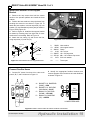
Install Hose Clamp Bracket & Channel
1. Install #40539 hose clamp bracket to right loader
mount, using carriage bolts (3), flat washers (4), lock
washers (5), and nuts as shown in Figure 9.
NOTE: Bracket must be installed before the loader is
mounted to the tractor.
2. With loader in mounting position, connect loader
supply hoses to the loader feedlines as shown in Figure 11.
3. Install #40548 hose clamp channel to hose clamp
bracket. Clamp hoses as shown in Figure 10.
5.
6.
10.
11.
12.
13.
14.
15.
40539
40548
35735
66840
3632
1286
230
5607
Hose clamp bracket
Hose clamp channel
3/8 NC x 2-1/2 Carriage bolt
3/8 NC Knob
5/8 Flat washer
5/8 Lock washer
5/8 NC Hex nut
5/8 NC x 1-1/2 Carriage bolt
+26( &/$03 &+$11(/
Figure 10 Hose Clamp Bracket & Channel Installed
%
'
FP
$
&
5+
/2$'(5
%220
$ %8&.(7 &</ %$6( (1'
'803
% %8&.(7 &</ 52' (1'
52//%$&.
& %220 &</ 52' (1'
'2:1
' %220 &</ %$6( (1'
83
Figure 9 Hose Clamp Assembly
Figure 11 Loader Feedline Identifications
(viewed from rear)
12 Hydraulic Installation
PN-46018 (Rev. 3/15/02)
1 #40542 Hose Kit Cont’d
Route Hoses & Install Hose Support
)8(/ 7$1.
6833257 &+$11(/
1. Route hydraulic hoses along loader mount, under
right side of fuel tank, and over the rear axle. Be sure
to avoid contact with 3-point linkage, brake pedals,
and other moveable tractor components.
IMPORTANT
■
Hoses must be routed so that they are not
pinched bent sharply, or chafed during operation.
Hoses must not interfere with any tractor control
operation or contact any moving parts.
2. Attach #40543 hose support to tractor fuel tank
support channel, using existing tractor hardware from
the fuel tank support channel. Route hoses through
hose support.
+26(
+26(
6833257
6833257
FP
Figure 12 Hose Support Installed
Install Fittings to Hoses
%RRP
/LIW +RVHV
1. Attach two adapters (1), 90-degree elbows (2), and
quick couplers A (not included), to boom cylinder hoses.
%XFNHW
&\OLQGHU +RVHV
2. Attach two 90-degree elbows (2) and quick couplers
(not included) to bucket cylinder supply hoses.
$
A.
66511
1.
2.
3.
4.
315058
313053
313032
53670
1/2 NPT Quick coupler
(not included)
1/2 NPT x 3/4 JICF Adapter
1/2 NPT x 3/4 JICF Elbow
3/4 JICM x 3/4 JICF Elbow
3/8 x 150” Hose
Figure 13 Hose Fitting Identifications
PN-46018 (Rev. 3/15/02)
Hydraulic Installation 13
1 #40542 Hose Kit Cont’d
Connect Hoses to Tractor
1. Connect hydraulic hoses to tractor hydraulic couplers as shown in Figure 14.
&
'
2. Refer to tractor operator’s manual for operating
the tractor hydraulic levers.
$
%
+26(
6833257
FP
Figure 14 Hose Connections to Tractor
Hydraulic Couplers
Verification of Control Movements
&21752/
1. Comply with all Safety Rules and start the tractor.
2. Check that all hydraulic control lever positions operate the loader movements correctly as
shown in Figure 15.
&21752/
3. If loader movements do not respond correctly, shut off tractor, relieve pressure, and
reconnect properly. Loader control movements
must be correct before proceeding.
4. Once all loader functions are correct, start
the tractor and operate the loader to check for
leaks. Purge any remaining air from the hydraulic
system.
5. When hose routings and correct loader operations are verified, identify each circuit by placing
a matching colored band around the male and
female quick-disconnect coupler set. The colored
bands will make re-installation easier when the
loader is removed from the tractor.
6. Be sure that adequate slack is left in the
hoses so they can move as the loader moves
through its full range of motion.
7. Before operating the loader, make sure that the
Pre-Delivery, Delivery, and Pre-Operation Checklists
from the Operator section in the Loader Operator’s
Manual have been completed.
&0
Figure 15 Tractor Hydraulic Control Levers
●
Control #1, Handle forward - Boom down
●
Control #1, Handle back - Boom up
●
Control #2, Handle forward - Dump bucket or
attachment
●
Control #2, Handle back - Rollback bucket or
attachment
14 Hydraulic Installation
PN-46018 (Rev. 3/15/02)
2
#56037 Control Valve & #40547 Hose Kit
(For use with loader joystick)
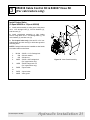
General Description
This hydraulic connection uses a single lever control
valve mounted on the right loader mount with a
bracket as shown in Figure 16.
&0
&0
Figure 16 #56037 Control Valve Installed
(Typical installation)
PN-46018 (Rev. 3/15/02)
Hydraulic Installation 15
2 #56037 Valve Kit & #40547 Hose Kit Cont’d
Assemble Control Valve Kit
1. Install the control lever:
a) Thread end of handle (9) into valve.
b) Align handle so that end with longer bend is
pointing toward the adapter fittings. Make sure
bends are in line with front and rear of valve.
c) Tighten jam nut (38) already installed on handle.
d) Slide boot down over boot bracket.
9
2. The valve mounting plate contains two sets of
holes. Select the holes that will position the valve in
the desired location. Install the valve mounting plate
(8) to the right loader mount, using two 5/8 NC x 1-1/2
carriage bolts (40), flat washers (41), lock washers
(42), and nuts (43) as shown.
38
17
3. Install 3/8 NC x 1-1/4 carriage bolt (30) throughback of mounting shoe, securing with flat washer (32),
lock washer (33), and nut (34).
35
Carriage bolts must be installed so that the head is
inside the loader mount.
4. Attach the valve mount to the valve plate so that
the control valve will be in the correct position for
operation. Secure with three 1/2 NC x 1-1/2 carriage
bolts (35), flat washers (36), lock washers (37), and
nuts (39) as shown.
5. Control valve must be positioned so that movement of tractor controls is not restricted. Maintain at
least 6” spacing between control valve kit and any
tractor control (brake pedals, accelerator, hand throttle, or hydraulic levers.) Check for clearances in the
operating position.
6. Torque all hardware to specifications given below.
TORQUE SPECIFICATIONS
Wrench
Size
Required Torque
3/8 NC x 1-1/4
Bolt
9/16”
35 lbs.-ft. (47 N-m)
1/2 NC x 1-1/2
3/4”
85 lbs.-ft.(115 N-m)
5/8 NC x 1-1/2
15/16”
170 lbs.-ft.(230 N-m)
8
33 34
32
30
36
40
37
39
41
42
43
CD5733
Figure 17 2-Spool Control Valve Kit Assembly
8.
9.
17.
30.
32.
33.
34.
35.
36.
37.
38.
39.
40.
41.
42.
43.
16 Hydraulic Installation
46340
56254
56095
20973
565
838
835
12735
3598
855
13859
1093
5607
3632
1286
230
Valve mounting plate
Bent handle
3/8 x 54” Hose
3/8 NC x 1-1/4 Carriage bolt
3/8 Flat washer
3/8 Lock washer
3/8 NC Hex nut
1/2 NC x 1-3/4 Carriage bolt
1/2 Flat washer
1/2 Lock washer
Jam nut
1/2 Hex nut
5/8 NC x 1-1/2 Carriage bolt
5/8 Flat washer
5/8 Lock washer
5/8 Hex nut
PN-46018 (Rev. 3/15/02)
2 #56037 Valve Kit & #40547 Hose Kit Cont’d
Assemble #40547 Hose Kit
IMPORTANT
■
If hydraulic lines are not connected as shown in the
mount installation manual or tractor manual, the loader
control valve may be damaged. A blocked outlet (return)
or improper hose connection will cause pressurized oil to
enter the return circuit and damage the valve or the tractor hydraulic system.
1. Connect 90-degree end of 80” hose (8) to OUT port
adapter and tighten.
2. Connect two 54” hoses (7) to PBY and IN port adapaters.
3. Route 80” hose between tractor fuel tank and operator
platform to tractor Return port and connect, using 90° elbow
(5) and adapter (3).
2.
3.
4.
5.
7.
8.
315038
315058
40549
313032
360130
57911
7
1/2 NPTF x 3/4 JICM Adapter
1/2 NPTM x 3/4 JICF Adapter
1/2 NPTM x M26 x 1.5M 90° Elbow
3/4 JICM x 3/4 JICF 90° Elbow
54” Hose
80” Hose
8
CD5558C
2
4
7
IN
5
3
2
OUT
12
TRACTOR
PART
4
4
11
15
POWER
BEYOND
10
Figure 17 #40547 Hose Kit Assembly
PN-46018 (Rev. 3/15/02)
Hydraulic Installation 17
2 #56037 Valve Kit & #40547 Hose Kit Cont’d
Install Fittings to Tractor Hydraulic Line
Refer to Figure 17 and Figure 18.
1. If not done during installation of right rear loader
mount, remove the tractor hydraulic line connector
tube or adapter block (if equipped) as shown in Figure
2.
&0
/,1(
6833257
%5$&.(7
NOTE: If 90-degree elbow (4) includes a nut and
sleeve, discard them.
2. Connect adapters (2) to each 90-degree elbow
(4) and tighten. NOTE: Use sealant on pipe threads.
3. Attach adapters (2) to PBY and IN hoses. Tighten
finger tight.
4. Route IN hose inside the right loader mount.
Install elbow onto end of tractor hydraulic line as
shown in Figure 18.
5. Route PBY hose inside right loader mount.
Remove plastic cap and install onto transmission end
of tractor hydraulic line as shown in Figure 18.
6. Point elbows up and slightly out to clear the
hydraulic Return line as shown.
7. Tighten elbows to tractor line and tighten hoses to
adapters.
72 /2$'(5
9$/9( ,1 3257
(1*,1( (1'
)520 /2$'(5 9$/9(
3%< 3257
75$160,66,21 (1'
Figure 18 Hose Hanger Bracket Installed
2.
4.
7.
11.
12.
13.
315038
40549
360130
480261
6128
300057
18 Hydraulic Installation
1/2 NPTF x 3/4 JICM Adapter
1/2 NPTM x M26 x 1.5M 90° Elbow
54” Hose
Clamp
1/4 NC Lock nut
1/4 NC x 3/4 Cap screw
PN-46018 (Rev. 3/15/02)
2 #56037 Valve Kit & #40547 Hose Kit Cont’d
Install Hose Retainer & Line Support
Bracket
1. Remove the cap screws that hold the tractor
fender to the operator platform and install the hose
retainer.
2. Position the hose retainer to keep the hoses from
touching the tractor tire as shown in Figure 20. To
attach the hose retainer, use new cap screw (14), lock
washer (15), and flat washer (tractor part) as shown in
Figure 19 and Figure 20.
3. Refer to Figure 18. Install the line support bracket
as shown by removing nuts from right side of crossmember then re-installing. Refer to Figure 19.
4. Attach the line clamp (11) and secure the line,
using cap screw (13) and nut (12).
&0
Figure 20 Hose Retainer Installed
12
TRACTOR
PART
11
14
15
10
CD5558C-Var
9
13
Figure 19 Hose Retainer & Line Support Bracket
9.
58859
10. 40546
11. 480261
12.
6128
13. 300057
14. 307129
15.
2472
16.
——
Hose retainer
Line support bracket
Clamp
1/4 Lock nut
1/4 x 3/4 Cap screw
M8 x 1.25 x 30mm Cap screw
5/16 Lock washer
Tractor part
Connect Feedline Hoses
1. Connect 54” hoses from hose kit to valve work
ports A, B, C, and D as shown in Figure 21.
,1
287
'
&
$ %8&.(7 &</ %$6( (1'
'803 5('
%
$
2. Identify the appropriate feedline locations and
connect opposite end of each hose to loader feedlines
as shown in Figure 21.
% %8&.(7 &</ 52' (1'
52//%$&. %/8(
& %220 &</ 52' (1'
'2:1 <(//2:
3%<
' %220 &</ %$6( (1'
83 *5((1
%
$
5+
/2$'(5
%220
'
&
/2$'(5 )(('/,1(6
Figure 21 #56037 Control Valve & Loader Feedline Connections
PN-46018 (Rev. 3/15/02)
Hydraulic Installation 19
2 #56037 Valve Kit & #40547 Hose Kit Cont’d
Torque Hardware & Tighten Fittings
1. Torque all hardware to specifications given below.
2. Check to be sure all hydraulic fittings are tight.
TORQUE SPECIFICATIONS
Wrench
Bolt
Qty
Size
Required Torque
1/4 x 3/4
1
7/16”
10 lbs.-ft.(13 N-m)
5/16 x 3/4
2
1/2”
19 lbs.-ft.(26 N-m)
3/8 x 1-1/2
4
9/16”
35 lbs.-ft. (47 N-m)
1/2 x 1-1/2
2
3/4”
85 lbs.-ft. (115 N-m)
5/8 x 1-1/2
2
15/16”
170 lbs.-ft. (230 N-m)
M8 x 1.25
2
13mm
15 lbs.-ft. (20 N-m)
Verification of Control Movements
)/2$7 326,7,21
1. Mount loader to tractor: Remove mount pins
from loader uprights. Align tractor with loader and
slowly drive tractor into loader. Shut off tractor.
2. Connect loader feedline hoses to control valve
hydraulic couplers.
75$&725
)5217
NOTE: At least 6” spacing should be maintained
between valve, bracket, or hoses and any tractor control (brake pedals, accelerator, hand throttle, or
hydraulic levers).
/(9(5
&21752/
/2:(5
'803
/,)7
52//%$&.
3. Comply with all Safety Rules and start the tractor.
4. Check that all hydraulic control lever positions
operate the loader movements correctly as shown in
Figure 22.
Figure 22 Single Lever Control Operation
●
Handle Forward - Boom down
5. If loader movements do not respond correctly,
shut off tractor, relieve pressure, and reconnect properly. Loader control movements must be correct
before proceeding.
●
Handle forward to limit - Float position
●
Handle back - Boom up
●
Handle to right - Dump bucket or attachment
6. Once all loader functions are correct, start the
tractor and operate the loader to check for leaks.
Purge any remaining air from the hydraulic system.
●
Handle to left - Rollback bucket or attachment
7. When hose routings and correct loader operations are verified, identify each circuit by placing a
matching colored band around the male and female
quick-disconnect coupler set. The colored bands will
make re-installation easier when the loader is
removed from the tractor
8. Be sure that adequate slack is left in the hoses so
they can move as the loader moves through its full
range of motion.
9. Before operating the loader, make sure that the
Pre-Delivery, Delivery, and Pre-Operation Checklists
from the Operator section in the Loader Operator’s
Manual have been completed.
20 Hydraulic Installation
PN-46018 (Rev. 3/15/02)
3
#56038 Cable Control Kit & #46047 Hose Kit
(For cab tractors only)
Install Control Valve
(2-Spool #56038 or 3-Spool #56042)
1
1. Install valve assembly to valve guard, using three
3/8 x 1-1/2 carriage bolts (1), 3/8 lock washers (2),
and hex nuts (3).
2. Install valve/guard assembly to right loader
mount, using three 3/8 x 1-1/2 carriage bolts (1), 3/8
lock washers (2), and hex nuts (3).
4
3
2
5
3. For 3-spool valve only: Use two 3/8 x 3/4 carriage bolts (4) and lock nuts (5) to hold valve guard to
mounting shoe.
NOTE: Carriage bolts must be installed so that heads
are inside loader mount frame.
1.
2.
3.
4.
301104
838
835
24597
5.
14350
6.
or
6.
7.
56250
3/8 NC x 1-1/2 Carriage bolt
3/8 Lock washer
3/8 Hex nut
3/8 NC x 3/4 Carriage bolt
(for 3-spool valve only)
3/8 NC Flange lock nut
(for 3-spool valve only)
2-spool valve
56270
46045
3-spool valve
Valve guard
PN-46018 (Rev. 3/15/02)
CD5817
6
7
Figure 23 Valve Guard Assembly
Hydraulic Installation 21
3 #56038 Valve Kit & #46047 Hose Kit Cont’d
Connect Controller to Cables
5(7$,1(5
%2/7
1. Slide the rubber control boot up out of the way.
Orient the controller as shown in Figure 24.
%8&.(7
&$%/(
&2//$5
2. Using a vice, clamp the controller loosely.
3. Remove both cable retainer bolts.
4. Push the control lever to expose the bucket cable
actuator at the bottom of the controller. Thread the
cable end to the cable actuator and tighten.
5. Push the control lever and insert the bucket cable
collar into the control lever body. Replace the cable
retainer bolt and tighten.
6. Push the control lever to expose the boom cable
actuator at the bottom of the controller. Thread the
cable end to the cable actuator and tighten.
7. Release the control lever and insert the boom
cable collar into the control lever body. Replace the
cable retainer bolt and tighten.
&21752/
/(9(5
%220
&$%/(
&2//$5
&0
Figure 24 Attaching Control Cables
to Control Lever
8. Remove the controller from the vice.
22 Hydraulic Installation
PN-46018 (Rev. 3/15/02)
3 #56038 Valve Kit & #46047 Hose Kit Cont’d
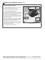
Install Controller Stand Bracket
NOTE: Use #46049 adapter plate and hardware from
#46047 Hose Kit.
1. Locate the control cable access hole under the
rubber floor mat in the right front corner of the tractor
cab.
723 9,(:
&DS
6FUHZV
WK &DS
6FUHZ
&DUULDJH
%ROW
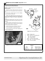
2. Insert three carriage bolts (2) into the adapter
plate (1) as shown in Figure 26.
3. Position the adapter plate over the holes in the
cab floor and install cap screws (6) and lock washers
(7) as shown in Figure 26. Torque to specifications
given.
&DUULDJH
%ROWV
NOTE: Before tightening three cap screws, verify that
the fourth cap screw will line up with the hole in the
cab floor.
4. Install controller mount bracket on top of the pre
installed carriage bolts and fasten with lock washers
(3) and nuts (4) as shown in Figure 25.
&$%
)/225
5. Install fourth cap screw as shown in Figure 26.
6. Torque all hardware to specifications given.
7. Trim the rubber floor mat and foam padding to fit
around the adapter plate.
&'$
&0
Figure 26 Control Stand Bracket
1.
2.
3.
4.
5.
6.
7.
46049
20973
838
835
56215
307129
2472
$'$37(5
3/$7(
TORQUE SPECIFICATIONS
Figure 25 Assembled Control Stand Bracket
Wrench
Bolt
PN-46018 (Rev. 3/15/02)
Adapter plate
3/8 NC x 1-1/4 Carriage bolt
3/8 Lock washer
3/8 NC Hex nut
Controller mount bracket
M8 x 1.25 x 30mm Cap screw
5/16 Lock washer
Size
Required Torque
M8 x 1.25
13mm
15 lbs.-ft.(20 N-m)
3/8 NC x 1.5
9/16”
35 lbs.-ft.(47 N-m)
Hydraulic Installation 23
3 #56038 Valve Kit & #46047 Hose Kit Cont’d
Install Controller Stand
1. Attach controller stand to controller mount
bracket, using four 3/8 x 1-1/4 carriage bolts, 3/8 flat
washers, lock washers, and nuts.
2. Attach controller to controller stand, using three
5/16 x 4-1/2 cap screws, 5/16 lock washers, and nuts.
NOTE: Be sure the handle is positioned with the
“float” position forward (see Figure 35).
3. Adjust the controller stand, maintaining at least 4”
spacing between the control ever and any restriction
(hand throttle, door, fender, or hydraulic levers).
4. Position the controller stand so that the loader
control movements will not be restricted.
5. Apply controller operational decals to a clean surface that is visible to the operator. See Figure 28 for
completed installation.
NOTE: If using a 3-spool valve, attach the auxiliary
controller to the outside of the controller stand, using
5/16 x 6 cap screws, 5/16 lock washers, and 5/16
nuts.
&RQWUROOHU 6WDQG
Figure 28 Controller Stand Installed
VSRRO YDOYH
VSRRO YDOYH
&RQWUROOHU
0RXQW
%UDFNHW
1.
2.
3.
20973
300110
301001
3/8 x 1-1/4 Carriage bolt
5/16 x 4-1/2 Cap screw
5/16 x 6 Cap screw
TORQUE SPECIFICATIONS
Wrench
Bolt
Size
Required Torque
5/16
1/2”
19 lbs.-ft.(26 N-m)
3/8
9/16”
35 lbs.-ft.(47 N-m)
Figure 27 Controller Stand Assembly
24 Hydraulic Installation
PN-46018 (Rev. 3/15/02)
3 #56038 Valve Kit & #46047 Hose Kit Cont’d
Attach Control Cables to Valve
1. Thread jam nut (g) over threaded end of cable.
2. Slide retainer (f) over cable.
3. Thread adjuster (e) completely over cable.
4. Thread jam nut (d) onto cable.
5. Thread cable adapter (a) onto end of cable.
Adapter should be installed so that three threads on
the cable remain visible at the jam nut.
a
6. Remove screws from retainer (c) while keeping
retainer in place.
b
7. Attach adapter (a) to the valve spool using pin (b).
Thread adjuster (e) onto cable to hold pin (b) in place.
c
CD5816
d
8. Install socket head cap screws (h) through the
assembly (c-f). Leave retainer (f) just loose enough to
allow adjuster (e) to be turned.
e
NOTE: Valve cable connect kit contains three sets of
socket head cap screws. Use 3/4” long screws for all
sections.
f
g
9. Turn the adjuster to remove all slack from the
cable housing and to keep the control lever centered.
h
BUCKET
AUXILIARY
(OPTIONAL)
BOOM
Figure 29 Control Cable Assembly
Adjust Control Cable
1. Check control lever operation before starting tractor. Lever should be centered and movement should
be equal in all directions except “float” position. Float
position is locked forward.
2. If the lever movement is not equal or the “float”
position cannot be engaged, adjust the cables as follows (refer to Figure 29):
3. Loosen the adjuster jam nut (g) and the retainer
cap screws (h) slightly so that adjuster (e) can be
turned by hand.
4. Rotate the adjust to move the control lever to center position.
6. Loosen the adapter jam nut (d) and turn the cable
adapter until movement is correct (lengthen cable by
turning 2 or 3 times).
7. Reconnect the cable adapter (a) and repeat cable
adjustment procedure (Steps 1-4).
8. When adjustment is complete, tighten jam nut (g)
and retainer cap screws (h) securely to hold cable
housing in place, but do not overtighten.
9. Torque cap screws to 10 lbs.-ft.
10. Use a plastic tie strap to secure the cables to the
loader mount.
5. If the lever cannot be adjusted for correct operation, remove the adjuster (e) and disconnect the cable
adapter (a) from the valve.
PN-46018 (Rev. 3/15/02)
Hydraulic Installation 25
3 #56038 Valve Kit & #46047 Hose Kit Cont’d
Connect Hydraulic Lines
IMPORTANT
■
If hydraulic lines are not connected as shown in
he mounting kit manual or the tractor manual, the
control valve my be damaged. A blocked outlet
return) or improper hose connection will cause
pressurized oil to enter the return circuit and damage the valve or the tractor hydraulic system.
■
Use care when identifying valve ports. Cable
operated loader valve is mounted in the inverted
position (stems down as shown in Figure 33.)
1
■
If tractor hydraulic system pressure is greater
han 2650 psi, make sure the valve used is
equipped with a relief valve.
CD5618C-Var
2
1
5
6
PBY
PYB
5
7
6
8
IN
OUT
Figure 30 #46047 Hose Kit
Install OUT Line
1. Connect 90-degree end of 100” hose (3) to adapter
in valve OUT port. Refer to Figure 30.
75$&725
5(7851
3257
2. Route hose under fuel tank, then over right rear
axle to tractor Return port (above the upper right of the
PTO shield) and connect. Use straight adapter (1) and
90-degree elbow (2) as shown in Figure 31.
1.
2.
3.
315058
313032
46044
1/2 NPTM x 3/4 JICF Adapter
3/4 JICM x 3/4 JICF 90° Elbow
100” Hose
&0
Figure 31 Tractor Return (OUT) Port
26 Hydraulic Installation
PN-46018 (Rev. 3/15/02)
3 #56038 Valve Kit & #46047 Hose Kit Cont’d
Install IN & PBY Lines
1. If not done during installation of right rear loader
mount, remove the tractor hydraulic line connector
tube or adapter block (if equipped) as shown in Figure
2, Page 7.
72 /2$'(5 9$/9(
,1 3257
(1*,1( (1'
NOTE: If 90-degree elbow includes a nut and a
sleeve, discard them.
2. Remove plastic cap from tractor hydraulic line.
3. Refer to Figure 30. Route hose (3) from valve IN
port outside the loader mount to elbow (1) installed to
the engine end of the hydraulic line as shown in Figure 32.
4. Refer to Figure 30. Route the hose (3) from valve
PBY port outside the loader mount to elbow (1)
installed in the transmission end of the hydraulic line
as shown in Figure 32.
1.
2.
3.
40549
315038
46046
)520 /2$'(5 9$/9(
3%< 3257
75$160,66,21 (1'
&0
Figure 32 Tractor PBY & IN Connections
1/2 NPTM x M26 x 1.5M 90° Elbow
1/2 NPTF x 3/4 JICM Adapter
38” Hoses
PN-46018 (Rev. 3/15/02)
Hydraulic Installation 27
3 #56038 Valve Kit & #46047 Hose Kit Cont’d
Connect Loader Feedline Hoses
1. The Control Valve Kit contains hoses assembled
with quick couplers. Attach the hoses to loader feedlines.
3. Connect auxiliary feedlines to loader feedline hoses.
Refer to Figure 33.
2. Connect loader feedline hoses to control valve
hydraulic couplers following the color scheme shown in
Figure 33.
)
3%<
$
&
% %8&.(7 &</ 52' (1'
52//%$&. %/8(
(
%
287
%
'
$ %8&.(7 &</ %$6( (1'
'803 5('
(
)
,1
$
5+
/2$'(5
%220
'
&
& /,)7 &</ 52' (1'
'2:1 <(//2:
' /,)7 &</ %$6( (1'
83 *5((1
( $8;,/,$5< &</ 52' (1'
:+,7(
6322/ &21752/ 9$/9(
/2$'(5
)(('/,1(6
) $8;,/,$5< &</ %$6( (1'
25$1*(
Figure 33 3-Spool Hydraulic Connection
Connect Hoses to Control Valve
/2$'(5
02817,1*
3,1
1. Route control cables to valve. Protect cables from
being crushed or pinched. Do not allow cable to be
kinked or stretched. Keep all bends in cable to an 8”
radius or greater.
2. Tighten fittings and align hoses as shown in Figure
34. Leave an opening to allow for installation and
removal of the loader mounting pin.
Figure 34 Hose Installation to Control Valve
28 Hydraulic Installation
PN-46018 (Rev. 3/15/02)
2 #56038 Valve Kit & #46047 Hose Kit Cont’d
3
Verification of Control Movements
1. Refer to the Woods Loader Operator’s Manual to
complete the loader installation. At least 6” spacing
should be maintained between valve, bracket, or
hoses and any tractor control (brake pedals, accelerator, hand throttle, or hydraulic levers).
)/2$7 326,7,21
/(9(5
&21752/
/2:(5
75$&725
)5217
'803
2. Comply with all Safety Rules and start the tractor.
3. Check that all hydraulic control lever positions
operate the loader movements correctly as shown in
Figure 35.
NOTE: When the optional auxiliary hydraulic control
is used for operating an attachment such as a grapple, pushing the control lever forward should close the
attachment and pulling the lever rearward should
open the attachment. See Figure 36.
4. If loader movements do not respond correctly,
shut off tractor, relieve pressure, and reconnect properly. Loader control movements must be correct
before proceeding.
5. Once all hoses are connected correctly, start the
tractor and operate the loader to check for leaks.
Purge any remaining air from the hydraulic system.
6. When hose routings and correct loader operations are verified, identify each circuit by placing a
matching colored band around the male and female
quick-disconnect coupler set. The colored bands will
make re-installation easier when the loader is remove
from the tractor.
7. Attach the plastic tie straps (included in kit) every
20 inches around the hoses to keep them tightly bundled and away from contact with the ground or other
moving parts on the tractor or loader.
8. Be sure the adequate slack is left in the hoses so
they can move as the loader moves through its full
range of motion.
9. Before operating the loader, make sure that the
Pre-Delivery, Delivery, and Pre-Operation Checklists
from the Operator section in the Loader Operator’s
Manual have been completed.
PN-46018 (Rev. 3/15/02)
/,)7
52//%$&.
Figure 35 Single Lever Control Operation
●
Handle Forward - Boom down
●
Handle forward to limit - Float position
●
Handle back - Boom up
●
Handle to right - Dump bucket or attachment
●
Handle to left - Rollback bucket or attachment
&/26(
23(1
- +DQGOH IRUZDUG &ORVH JUDSSOH
- +DQGOH UHDUZDUG 2SHQ JUDSSOH
Figure 36 Auxiliary Control Operation
Hydraulic Installation 29
NOTES
30 Hydraulic Installation
PN-46018 (Rev. 3/15/02)
PARTS INDEX
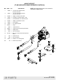
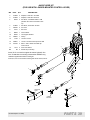
111868 LOADER MOUNTING KIT
Loaders
Loaders
1020
255
255
1027
260
260
mounting to
Kubota Tractor Models
M8200
M9000
#111868 LOADER MOUNT KIT . . . . . . . . . . . . . . . . . . . . . . . . . . . . . . 32
#40542 HOSE KIT
(For use with tractor remotes). . . . . . . . . . . . . . . . . . . . . . . . . . . . . . . . 33
#56037 CONTROL VALVE KIT
(For use with loader-mounted control lever) . . . . . . . . . . . . . . . . . . 34-35
#56038/#56042 CABLE CONTROL VALVE KIT
(For tractors with cab) . . . . . . . . . . . . . . . . . . . . . . . . . . . . . . . . . . . 36-37
#46047 HOSE KIT
(For use with cable-operated controls) . . . . . . . . . . . . . . . . . . . . . . . . . 38
#40547 HOSE KIT
(For use with loader-mounted control lever) . . . . . . . . . . . . . . . . . . . . . 39
PN-46018 (Rev. 11/10/00)
PARTS 31
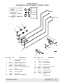
111868 LOADER MOUNTING KIT
1
13
18
22
7
11
5
12
4
14
2
7
1
12
8
20
9
22
16
6
12
3
CD5612C
11
13
23
17
11
12
13
11
11
REF
PART
QTY
DESCRIPTION
REF
PART
QTY
DESCRIPTION
1
44490
1
Right rear mount
2
44491
1
Left rear mount
3
1002896
1
Front mount bracket
4
46000
1
Crossmember
5
59628
1
Right side rail
6
59631
1
Left side rail
18
7
46015
2
Spacer plate
(use only on non-cab models only)
19
307502
2
8
1000545
1
Grill guard
M18 x 1.5 x 85mm Hex head cap
screw GR8.8
9
57816
2
1/2 SAE Hardened flat washer
20
56059
1
Decal, loader mounting instructions
11
57817 38 5/8 Flat washer
22
57798 14 3/4 SAE Hardened flat washer
230 24 5/8 NC Hex nut
23
——— — Front anchor (no longer used; order
1002896, item 3)
12
13
4548 20 5/8 NC x 1-3/4 Hex head cap screw
GR5
32 PARTS
14
12274
4
5/8 NC x 2-1/4 Hex head cap screw
GR5
16
67376
2
M12 x 1.25 x 80mm Hex head cap
screw GR10.9
17
307425
6
M16 x 1.5 x 35mm Hex head cap
screw GR8.8
46019 12 M18 x 1.5 x 70mm Hex head cap
screw GR8.8
(Rev. 3/15/02)
PN-46018 (Rev. 11/10/00)
#40542 HOSE KIT
(FOR USE WITH TRACTOR REMOTE CONTROL LEVER)
$ %8&.(7 &</ %$6( (1'
'803
% %8&.(7 &</ 52' (1'
52//%$&.
& %220 &</ 52' (1'
'2:1
%
$
'
&
' %220 &</ %$6( (1'
83
%RRP
/LIW +RVHV
5+
/2$'(5
%220
%XFNHW
&\OLQGHU +RVHV
$
&'$
REF
PART
QTY
DESCRIPTION
REF
PART
QTY
DESCRIPTION
A
66511
4
Quick coupler ISO 1/2 NPT
(not included)
11
66840
2
3/8 NC Knob
12
3632
2
5/8 Flat washer
1
315058
2
Adapter, 1/2 NPT x 3/4 JICF
13
1286
2
5/8 Lock washer
2
313053
2
Elbow, 1/2 NPT x 3/4 JICF
14
230
2
5/8 NC Hex nut
3
313032
2
Elbow, 3/4 JICM x 3/4 JICF
15
5607
2
5/8 NC x 1-1/2 Carriage bolt
4
53670
4
3/8 x 150” Hose w/clamped protective
shield
NS
395061
2
Spiral band, red
NS
395062
2
Spiral band, blue
NS
395063
2
Spiral band, orange
NS
54124
2
Spiral band, white
NS
88
6
5
40539
1
Hose clamp bracket
6
40548
1
Hose clamp channel
7
40543
1
Hose support
10
35735
2
3/8 NC x 2-1/2 Carriage bolt
PN-46018 (Rev. 11/10/00)
Plastic tie
NS = Not Shown
PARTS 33
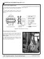
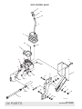
56037 CONTROL VALVE
11
10
38
9
4
28
38
3
1
12
31
18(2)
15
2
8
24
34
12
16
33
35
33
34
18(1)
19
32
30
16
36
40
37
21-26
39
41
17
42
43
CD5736v ar-1
34 PARTS
(Rev. 3/15/02)
PN-46018 (Rev. 11/10/00)
56037 CONTROL VALVE PARTS LIST
REF
PART
QTY
DESCRIPTION
REF
PART
QTY
DESCRIPTION
1
56251
1
2-Spool valve with controller
22
395062
2
Spiral band, blue
2
45056
1
2-Spool valve mount
23
56061
2
Spiral band, green
3
46305
1
Boot bracket
24
56062
2
Spiral band, yellow
4
40527
1
Rubber control boot (2-spool)
28
56268
2
1/4 NC x 5/8 Button head cap screw
8
46340
1
Valve mounting plate
30
20973
1
3/8 x 1-1/4 Carriage bolt
9
56254
1
Bent handle, 0.5 OD x 11.31
31
12169
3
3/8 NC x 1-1/4 Hex head cap screw
10
45003
1
Knob, 1.88 diameter x 1/2 NC
32
565
1
3/8 Flat washer
11
45002
1
Valve control decal
33
838
4
3/8 Lock washer ZP
12
316016
3
Adapter, 3/4 JICM x 7/8 ORBM
34
835
4
3/8 NC Plated hex nut
15
45001
4
45° Elbow, 3/8 NPTM x 3/4 ORBM
35
12735
3
1/2 NC x 1-3/4 Carriage bolt HT
16
316007
4
Quick-attach coupler
36
3598
3
1/2 SAE Flat washer
17
56095
4
3/8 x 54” Hose, 3/8 NPTM x 3/4 JICM
37
855
3
1/2 Lock washer ZP
18
1082312
2
Plug, 7/8 x 14 (For open-center
systems only; one replaces Item 12 in
PBY port; one replaces Item 20 shutoff plug)
38
13859
2
1/2 NC Jam nut
39
1093
3
1/2 NC Plated hex nut
40
5607
2
5/8 NC x 1-1/2 Carriage bolt
Relief valve assembly
41
3632
2
5/8 SAE Standard flat washer
1286
2
5/8 Lock washer ZP
230
2
5/8 Plated hex nut
19
56252
1
20
X102202
1
MRV Shut-off plug
42
21
395061
2
Spiral band, red
43
(Rev. 3/15/02)
PN-46018 (Rev. 11/10/00)
PARTS 35
36 PARTS
PN-46018 (Rev. 11/10/00)
43
31
3
11
1
37
35
39
4
40
41
32
2
40
34
39
33
41
13
22
21
14
23
22
15
24
21
9
16
16
19
23
18
20(1)
24
12
CABLE CONTROL VALVE PARTS
#56038 - 2 Spool Valve
#56042 - 3 Spool Valve
17
41
20(2)
40
7
f
h
b
CD5737
e
g
c
d
a
10
38
8
6
42
36
CABLE CONTROL VALVE PARTS LIST
#56038 - 2 SPOOL VALVE
#56042 - 3 SPOOL VALVE
REF
PART
QTY
REF
REF
PART
QTY
REF
1
56214
1
Controller stand
21
395061
2
Spiral band, red
2
56215
1
Controller mount bracket
22
395062
2
Spiral band, blue
3
488010
1
Dual axis controller
23
56061
2
Spiral band, green
4
488011
1
Single axis controller (56042)
24
56062
2
Spiral band, yellow
6
46045
1
Valve guard
25
395063
2
Spiral band, orange (not shown)
7
56250
1
Husco 2-spool valve (56038)
26
54124
2
Spiral band, white (not shown)
31
300110
3
5/16 NC x 4-1/2 Cap screw (56038)
3
5/16 NC x 6 Cap screw (56042)
or
or
7
56270
1
Husco 3-spool valve (56042)
8
56252
1
Relief valve, 2650 psi
9
56210 AR 66” Control cable
32
10
56209 AR Husco valve kit connectors
(2 for 2-spool, 3 for 3-spool;
includes items A-H
4378 AR 5/16 Flat washer
(3 for 2-spool, 6 for 3-spool)
33
2472 AR 5/16 Lock washer
(3 for 2-spool, 6 for 3-spool)
34
4529 AR 5/16 NC Hex nut
(3 for 2-spool, 6 for 3-spool)
11
12
13
2
1
Grommet
31
46048 AR Hose 3/8 x 48”
316007 AR Quick coupler set
301101
35
839
4
3/8 NC x1 Cap screw
24597
2
3/8 NC x 3/4 Carriage bolt (56042)
14
8472 AR Elbow, 3/8 NPTM x 3/8 NPSM
(4 for 2-spool, 6 for 3-spool)
36
37
20973
4
3/8 NC x 1-1/4 Carriage bolt
15
315039 AR Adapter, 3/8 NPTM x 3/8 NPSM
(4 for 2-spool, 6 for 3-spool)
38
301104
3
3/8 NC x 1-1/2 Carriage bolt
39
21757
6
3/8 SAE Flat washer
16
315043 AR Adapter, 3/4 ORM x 3/8 NPTM
(4 for 2-spool, 6 for 3-spool)
40
17
1009
1
Adapter, 1/2 NTPF x 7/8 ORBM
18
315057
1
Adapter, 1/2 NPTM x 3/4 JICM
19
316016
2
Adapter, 3/4 JICM x 7/8 ORBM
20
1082312
2
Plug, 7/8 x 14 (Used for open-center
systems only; one replaces items 17 &
18 in PBY port; one replaces shut-off
plug)
(Rev. 11/27/00)
PN-46018 (Rev. 11/10/00)
41
838 11 3/8 Lock washer
835 11 3/8 NC Hex nut
42
14350
2
3/8 NC Flanged lock nut (56042)
43
45005
3
Control valve ball stud (repair part
for dual axis controller, item 3)
NS
260274
1
Decal, Instructional control
NS
56889
1
Decal, Auxiliary hydraulic control
NS
88
2
Plastic tie straps
AR
=
As Required
NS
=
Not Shown
PARTS 37
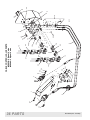
#46047 HOSE KIT
(TO BE USED WITH CABLE-OPERATED CONTROLS)
REF
PART
QTY
NOTE: Kit contains fittings that are not needed for
the M8200 or M9000 tractor.
DESCRIPTION
1
46046
2
1/2 X 38” Hose without sleeve,
3/4 JICF x 3/4 JICF
2
46044
1
1/2 x 100” hose without sleeve,
3/4 JICF x 3/4 JICF
5
315038
2
Adapter, 1/2 NPTF x 3/4 JICM
6
40549
2
90° Elbow, 1/2 NPTM x M26 x 1.5M
7
313032
1
90° Swivel elbow, 3/4 JICM x 3/4 JICF
8
315058
1
Adapter, 1/2 NPTM x 3/4 JICF
9
40543
1
Hose support
10
40546
1
Line support bracket
11
480261
1
Clamp
12
6128
1
1/4 NC Lock nut
13
300057
1
1/4 NC x 3/4 Hex head cap screw GR5
14
46049
1
Adapter plate
15
2472
4
5/16 Lock washer
16
307129
4
M8 x 1.25 x 30mm Hex head cap screw
GR8.8
17
835
3
3/8 NC Hex nut
18
838
3
3/8 Lock washer
19
20973
3
3/8 NC x 1-1/4 Carriage bolt
NS
88
3
Plastic tie (not shown)
1
2
16
15
17
1
18
5
6
14
12
PYB
PBY
19
11
5
7
CD5618C
6
8
10
IN
OUT
13
9
9
38 PARTS
(Rev. 3/15/02)
PN-46018 (Rev. 11/10/00)
#40547 HOSE KIT
(FOR USE WITH LOADER-MOUNTED CONTROL LEVER)
REF
PART
QTY
DESCRIPTION
2
315038
2
Adapter, 1/2 NPTF x 3/4 JICM
3
315058
1
Adapter, 1/2 NPTM x 3/4 JICF
4
40549
2
90° Elbow, 1/2 NPTM x M26 x 1.5M
(discard nut & sleeve to install on tractor)
5
313032
1
90° Elbow, 3/4 JICM x 3/4 JICF
7
360130
2
54” Hose
8
57911
1
80” Hose
9
58859
1
Hose retainer
10
40546
1
Line support bracket
11
480261
1
Clamp
12
6128
1
1/4 NC Lock nut
13
300057
1
1/4 NC x 3/4 Hex head cap screw GR5
14
307129
3
M8 x 1.25P x 30mm Hex head cap
screw CL8.8
15
2472
3
5/16 Lock washer
NS
88
3
Plastic tie (not shown)
7
Items 10-13 are used to support the tractor hydraulic line.
Item 10 attaches to mounting crossmember #59265 using
8
hardware supplied with loader mounting kit.
Items 9,14, and 15 are used as a hose guide for 80” hoses, item 8.
CD5558C
2
4
7
IN
5
3
2
OUT
12
TRACTOR
PART
4
14
11
15
POWER
BEYOND
10
9
13
13
PN-46018 (Rev. 11/10/00)
PARTS 39
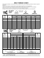
BOLT TORQUE CHART
Always tighten hardware to these values unless a different torque value or tightening procedure is listed for a specific
application.
Fasteners must always be replaced with the same grade as specified in the manual parts list.
Always use the proper tool for tightening hardware: SAE for SAE hardware and Metric for metric hardware.
Make sure fastener threads are clean and you start thread engagement properly.
All torque values are given to specifications used on hardware defined by SAE J1701 & J1701M JUL96.
SAE Bolt Head
Identification
SAE SERIES
TORQUE
CHART
A
SAE Grade 2
(No Dashes)
SAE Grade 8
(6 Radial Dashes)
SAE Grade 5
(3 Radial Dashes)
MARKING ON HEAD
A
SAE 2
SAE 5
SAE 8
Diameter
(Inches)
Wrench
Size
Lbs.-Ft.
N-m
Lbs.-Ft.
N-m
Lbs.-Ft.
N-m
1/4”
7/16”
6
8
10
13
14
18
5/16”
3/8”
1/2”
9/16”
12
23
17
31
19
35
26
47
27
49
37
67
7/16”
1/2”
5/8”
3/4”
36
55
48
75
55
85
75
115
78
120
106
163
9/16”
5/8”
13/16”
15/16”
78
110
106
149
121
170
164
230
171
240
232
325
3/4”
7/8”
1-1/8”
1-5/16”
192
306
261
416
297
474
403
642
420
669
569
907
1”
1-1/2”
467
634
722
979
1020
1383
A
METRIC SERIES
TORQUE
CHART
A
Metric Bolt Head
Identification
8.8
Metric
Grade 8.8
10.9
Metric
Grade 10.9
COARSE THREAD
FINE THREAD
MARKING ON HEAD
MARKING ON HEAD
A
Diameter &
Thread Pitch
(Millimeters)
Wrench
Size
N-m
Lbs.-Ft.
N-m
Lbs.-Ft.
N-m
Lbs.-Ft.
N-m
Lbs.-Ft.
Diameter &
Thread Pitch
(Millimeters)
6 x 1.0
8 x 1.25
10 mm
13 mm
8
20
6
15
11
27
8
20
8
21
6
16
11
29
8
22
6 x 1.0
8 x 1.0
10 x 1.5
12 x 1.75
16 mm
18 mm
39
68
29
50
54
94
40
70
41
75
30
55
57
103
42
76
10 x 1.25
12 x 1.25
14 x 2.0
16 x 2.0
21 mm
24 mm
109
169
80
125
151
234
111
173
118
181
87
133
163
250
120
184
14 x 1.5
16 x 1.5
18 x 2.5
20 x 2.5
27 mm
30 mm
234
330
172
244
323
457
239
337
263
367
194
270
363
507
268
374
18 x 1.5
20 x 1.5
22 x 2.5
24 x 3.0
34 mm
36 mm
451
571
332
421
623
790
460
583
495
623
365
459
684
861
505
635
22 x 1.5
24 x 2.0
30 x 3.0
46 mm
1175
867
1626
1199
1258
928
1740
1283
30 x 2.0
Metric 8.8
Typical Washer Installations
Bolt
Lockwasher
Nut
40 APPENDIX
Metric 10.9
Metric 8.8
Metric 10.9
Flat Washer
8/9/00
Bolt Torque & Size Charts (Rev. 2/5/02)
BOLT SIZE CHART
NOTE: Chart shows bolt thread sizes and corresponding head (wrench) sizes for standard SAE and metric bolts.
SAE Bolt Thread Sizes
5/16
3/8
1/2
5/8
3/4
7/8
IN
1
2
3
4
5
6
7
MM
25
50
75
100
125
150
175
Metric Bolt Thread Sizes
8MM
10MM
12MM
14MM
16MM
18MM
ABBREVIATIONS
AG ............................................................ Agriculture
NC ....................................................National Coarse
ATF ..............................Automatic Transmission Fluid
NF ......................................................... National Fine
BSPP ...........................British Standard Pipe Parallel
NPSM ...................National Pipe Straight Mechanical
BSPTM .............. British Standard Pipe Tapered Male
NPT......................................... National Pipe Tapered
CV...................................................Constant Velocity
NPT SWF........National Pipe Tapered Swivel Female
CCW ............................................ Counter-Clockwise
ORBM ......................................... O-Ring Boss - Male
CW............................................................. Clockwise
P .........................................................................Pitch
F .....................................................................Female
PBY .................................................... Power Beyond
GA ...................................................................Gauge
psi ........................................Pounds per Square Inch
GR (5, etc.) ......................................... Grade (5, etc.)
PTO ................................................... Power Take Off
HHCS ...................................... Hex Head Cap Screw
QD ..................................................Quick Disconnect
HT ..........................................................Heat Treated
RH ............................................................Right Hand
JIC ...............Joint Industry Council 37° Degree Flare
ROPS ......................... Roll Over Protective Structure
LH ............................................................... Left Hand
RPM...................................... Revolutions Per Minute
LT..........................................................................Left
RT ...................................................................... Right
m....................................................................... Meter
SAE ........................Society of Automotive Engineers
mm.............................................................. Millimeter
UNC ....................................................Unified Coarse
M.........................................................................Male
UNF ........................................................ Unified Fine
MPa .......................................................Mega Pascal
UNS ....................................................Unified Special
N .................................................................... Newton
Bolt Torque & Size Charts (Rev. 9/5/00)
APPENDIX 41
WARRANTY
(Replacement Parts For All Models Except Mow’n Machines)
WEC Company, d/b/a Woods Equipment Company (“WOODS”), warrants this product to be free from
defect in material and workmanship for a period of ninety (90) days from the date of delivery of the product
to the original purchaser with the exception of V-belts, which will be free of defect in material and workmanship for a period of 12 months.
Under no circumstances will this Warranty apply in the event that the product, in the good faith opinion of
WOODS, has been subjected to improper operation, improper maintenance, misuse, or an accident. This
Warranty does not cover normal wear or tear, or normal maintenance items.
This Warranty is extended solely to the original purchaser of the product. Should the original purchaser sell
or otherwise transfer this product to a third party, this Warranty does not transfer to the third party purchaser
in any way. There are no third party beneficiaries of this Warranty.
WOODS’ obligation under this Warranty is limited to, at WOODS’ option, the repair or replacement, free of
charge, of the product if WOODS, in its sole discretion, deems it to be defective or in noncompliance with
this Warranty. The product must be returned to WOODS with proof of purchase within thirty (30)
days after such defect or noncompliance is discovered or should have been discovered, routed through
the dealer and distributor from whom the purchase was made, transportation charges prepaid.
WOODS shall complete such repair or replacement within a reasonable time after WOODS receives the
product. THERE ARE NO OTHER REMEDIES UNDER THIS WARRANTY. THE REMEDY OF
REPAIR OR REPLACEMENT IS THE SOLE AND EXCLUSIVE REMEDY UNDER THIS WARRANTY.
THERE ARE NO WARRANTIES WHICH EXTEND BEYOND THE DESCRIPTION ON THE FACE OF
THIS WARRANTY. WOODS MAKES NO OTHER WARRANTY, EXPRESS OR IMPLIED, AND
WOODS SPECIFICALLY DISCLAIMS ANY IMPLIED WARRANTY OF MERCHANTABILITY AND/
OR ANY IMPLIED WARRANTY OF FITNESS FOR A PARTICULAR PURPOSE.
WOODS shall not be liable for any incidental or consequential losses, damages or expenses, arising
directly or indirectly from the product, whether such claim is based upon breach of contract, breach
of warranty, negligence, strict liability in tort or any other legal theory. Without limiting the generality
of the foregoing, Woods specifically disclaims any damages relating to (i) lost profits, business, revenues or
goodwill; (ii) loss of crops; (iii) loss because of delay in harvesting; (iv) any expense or loss incurred for
labor, supplies, substitute machinery or rental; or (v) any other type of damage to property or economic loss.
This Warranty is subject to any existing conditions of supply which may directly affect WOODS’ ability to
obtain materials or manufacture replacement parts.
No agent, representative, dealer, distributor, service person, salesperson, or employee of any company,
including without limitation, WOODS, its authorized dealers, distributors, and service centers, is authorized
to alter, modify, or enlarge this Warranty.
Answers to any questions regarding warranty service and locations may be obtained by contacting:
Woods Equipment
Company
2606 Illinois Route 2 South
Post Office Box 1000
Oregon, Illinois 61061
815-732-2141 tel
815-732-7580 fax
F-8494 3/1/2000 (Rev. 1/1/2002)
WARRANTY
(All Models Except Mow’n Machines)
Please Enter Information Below and Save For Future Reference.
Date Purchased: __________________________
From (Dealer): _____________________________
Model Number: __________________________
Serial Number: _____________________________
WEC Company, d/b/a Woods Equipment Company (“WOODS”), warrants this product to be free from defect in material
and workmanship. Except as otherwise set forth below, the duration of this Warranty shall be for TWELVE (12) MONTHS
COMMENCING ON THE DATE OF DELIVERY OF THE PRODUCT TO THE ORIGINAL PURCHASER.
The warranty period for certain gearboxes are listed below:
Model No.
1160, 1190, BB600, BB720, BB840, BB6000,
BB7200, BB8400
1130, 3180, 3240, BB48, BB60, BB72, BB84
Part Warranted
Duration
Gearbox components
Gearbox components
XT148, XT160, XT172, XT184
Rotary cutter gearbox
5 years from the date of delivery.
3 years from the date of delivery.
90 days from the date of delivery if used
in rental or commercial applications.
Under no circumstances will this Warranty apply in the event that the product, in the good faith opinion of WOODS, has been
subjected to improper operation, improper maintenance, misuse, or an accident. This Warranty does not apply in the event that
the product has been materially modified or repaired by someone other than WOODS, a WOODS authorized dealer or distributor, and/or a WOODS authorized service center. This Warranty does not cover normal wear or tear, or normal maintenance
items. This Warranty also does not cover repairs made with parts other than those obtainable through WOODS.
This Warranty is extended solely to the original purchaser of the product. Should the original purchaser sell or otherwise transfer this product to a third party, this Warranty does not transfer to the third party purchaser in any way. There are no third party
beneficiaries of this Warranty.
WOODS makes no warranty, express or implied, with respect to engines, batteries, tires or other parts or accessories not manufactured by WOODS. Warranties for these items, if any, are provided separately by their respective manufacturers.
WOODS’ obligation under this Warranty is limited to, at WOODS’ option, the repair or replacement, free of charge, of the
product if WOODS, in its sole discretion, deems it to be defective or in noncompliance with this Warranty. The product must
be returned to WOODS with proof of purchase within thirty (30) days after such defect or noncompliance is discovered or should have been discovered, routed through the dealer and distributor from whom the purchase was made,
transportation charges prepaid. WOODS shall complete such repair or replacement within a reasonable time after WOODS
receives the product. THERE ARE NO OTHER REMEDIES UNDER THIS WARRANTY. THE REMEDY OF REPAIR OR
REPLACEMENT IS THE SOLE AND EXCLUSIVE REMEDY UNDER THIS WARRANTY.
THERE ARE NO WARRANTIES WHICH EXTEND BEYOND THE DESCRIPTION ON THE FACE OF THIS WARRANTY. WOODS MAKES NO OTHER WARRANTY, EXPRESS OR IMPLIED, AND WOODS SPECIFICALLY DISCLAIMS ANY IMPLIED WARRANTY OF MERCHANTABILITY AND/OR ANY IMPLIED WARRANTY OF FITNESS
FOR A PARTICULAR PURPOSE.
WOODS shall not be liable for any incidental or consequential losses, damages or expenses, arising directly or indirectly from the product, whether such claim is based upon breach of contract, breach of warranty, negligence, strict
liability in tort or any other legal theory. Without limiting the generality of the foregoing, Woods specifically disclaims any
damages relating to (i) lost profits, business, revenues or goodwill; (ii) loss of crops; (iii) loss because of delay in harvesting;
(iv) any expense or loss incurred for labor, supplies, substitute machinery or rental; or (v) any other type of damage to property
or economic loss.
This Warranty is subject to any existing conditions of supply which may directly affect WOODS’ ability to obtain materials or
manufacture replacement parts.
No agent, representative, dealer, distributor, serviceperson, salesperson, or employee of any company, including without limitation, WOODS, its authorized dealers, distributors, and service centers, is authorized to alter, modify, or enlarge this Warranty.
This Warranty is effective only if the warranty registration card is returned within ten (10) days.
Answers to any questions regarding warranty service and locations may be obtained by contacting:
Woods Equipment
Company
2606 Illinois Route 2 South
Post Office Box 1000
Oregon, Illinois 61061
815-732-2141 tel
815-732-7580 fax
F-3079 Effective 3/2/2000 (Revised 3/1/01)
MANUAL
PART NUMBER
46018
Woods Equipment
Company
2606 Illinois Route 2 South
Post Office Box 1000
Oregon, Illinois 61061
815-732-2141 tel
815-732-7580 fax
© 1999 Woods Equipment Company. All rights reserved.