1
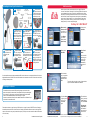
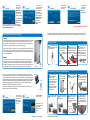
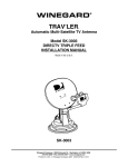
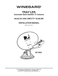
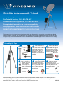
Satellite Antenna with Tripod
www.winegard.com
For Technical Services, Call 1-800-788-4417
For Receivers and Programming, Call 1-866-609-9374
For up-to-date information on receiver compatibility
and programming, visit www.winegard.com/receivers
TR-6018
DO NOT RETURN ANTENNA TO PLACE OF PURCHASE.
This manual provides instructions for both assembling and disassembling your tripod mount with home digital
satellite antenna. To set up your tripod mount with satellite antenna, begin with assembling the tripod. The tripod
requires only a one-time assembly and can be stored between uses. See page 7 for more information on storage
and disassembly.
Assembling the Tripod
Parts
legs (3)
Find a place to set
up the tripod with a
clear view of the southern
sky. Avoid obstructions
such as trees, hills, or
buildings—these can
block the signal from the
satellite.
1
bubble
level
storage
bag
stakes (3)
tripod base
Push in the tabs on
either side of one
leg, and slide the leg into
the tripod base until the
leg locks into the desired
position. Repeat for all three legs.
2
tabs
3
Place the bubble
level on top of the
tripod, and push
down until the
level snaps into
place. Loosen the
lock knobs on the
tripod base.
lock knob
Slide legs toward or
away from the base
until the bubble rests in
the center of the bubble
level. The tripod is now
level. Tighten the lock
knobs, and remove the
bubble level.
4
bubble should
be in the center
For extra stability,
insert the stakes
into the holes on the
pivot feet of the legs, and
push the stakes into the
ground. Check that
the tripod is still
level.
5
pivot
foot
After assembling the tripod, follow the instructions to assemble the satellite antenna. If the satellite antenna is
already assembled but is being set up at a new location, follow the instructions for receiver setup. Turn to
page 3 for DISH® receiver setup or to page 5 for DIRECTV® receiver setup.
2452225
1
Assembling the Home Digital Satellite Antenna
Parts
DISH Receiver Setup
18” reflector
10-32 flange
hex nut
50’ RG-6
coaxial cable
Insert the four 1/420 x 5/8” carriage
bolts through the four
holes on the front of the
reflector. Thread a 1/4-20
hex nut onto each bolt.
2
1
1/4-20 hex nut (4)
back-up/feed
support assy.
feed arm
DISH receivers will often not show when they are on signal if they have
incorrect “Check Switch” information. For this reason, DISH users must clear
current settings before pointing. To do this for most DISH receivers, follow
these steps. The following instructions are based on a ViP 211 receiver. Note
that if this is the first time using the receiver, the receiver may automatically
jump to step 4 of the instructions. If your receiver differs from the options
shown, you may need to consult your receiver manual. The wording and
display used in your receiver may differ slightly.
Line up the four
holes on the back
of the reflector with the
four holes on the backup/feed support assy. 1/4-20 x 5/8”
carriage bolt (4)
10-32 x 1-1/4”
carriage bolt
holes
LNBF
Thread the 50’ RG-6
coaxial cable
through the feed arm of
the back-up/feed support
assy.
3
holes
Screw the RG-6
coaxial cable onto
the LNBF. The coaxial
cable can be screwed
onto either port.
For Help, Call 1-800-788-4417
1
4
Connect the LNBF
and feed arm by
pushing the parts
together.
5
hex nuts
Insert the 10-32 x
1-1/4” carriage bolt
through the feed arm.
Then, thread the 10-32 flange hex
nut onto
the bolt.
6
2
Select option 1,
Installation.
4
Select Check
Switch.
Press Menu on
your remote.
Select option 6,
System Setup.
coaxial cable
hex nuts
Before starting,
disconnect coax
from “Sat in” on
back of receiver.
feed arm
Loosen the azimuth
hex nuts on the
back-up/feed support assy,
and slide the unit onto the tripod
azimuth
mast.
7
hex nuts
Continue with the
receiver setup
instructions. See page
3 for DISH receiver
setup, or see page 5 for
DIRECTV receiver setup.
Tighten all hex nuts after
pointing the dish.
8
Once the satellite antenna has been assembled, the RG-6 coaxial cable now runs through the feed arm of the home
digital satellite antenna. The 50’ RG-6 coaxial cable needs to be connected to the receiver. Connect the coaxial cable
according to the steps below.
3
Select option 1,
Point Dish.
If this is the first
time using your
receiver, your
receiver may
automatically
start with this
step.
5
Check that there
are no checkmarks
by SuperDISH or
Alternate. Select
Test.
The receiver will go through a number of steps and then
may warn that fewer satellites were detected.
Connecting to the Receiver
;
‘;
‘;
‘;
‘;
‘;
‘;
The satellite receiver powers the LNB by sending voltage up the coaxial cable.
Items such as splitters, video switches, and wall plates will stop the satellite signal.
For this reason, it is important to run the coaxial cable directly from the satellite
receiver to the satellite dish/antenna when searching for a signal.
Connect the coaxial cable directly from the satellite antenna to the “Satellite In” port
on the back of the satellite receiver.
6
“Satellite In” port
Follow the instructions on page 3 to set up a DISH receiver or on page 5 to set up a DIRECTV receiver. If setting up
the satellite antenna and receiver for the first time or if setting up the satellite antenna at a new location, begin with
step one of the receiver setup, and proceed with every step. Consult your receiver manual for additional information
on receiver setup.
2
Satellite Antenna with Tripod Kit
Satellite Antenna with Tripod Kit
If so, select Save.
It may ask you to
confirm. If so,
select Save
again.
7
This should clear
out any previously
installed devices.
Then, select Done.
Re-connect the
coaxial cable to
the “Satellite In”
port on the back
of the receiver.
Disclaimer: Receiver setup instructions are accurate at time of printing and may
change without notice. Call Winegard tech line for assistance: 1-800-788-4417.
3
8
Input zip code of current location and dish type. On the display, Dish System
should always be Dish 300. Note that whenever you move the satellite antenna
to a new location, you must enter the zip code of your new current location.
DIRECTV Receiver Setup
In most receivers, the setup is done through the “Repeat Satellite Setup” option in your
receiver menu. The following instructions are based on a D12 receiver. If your receiver
differs from the options shown, you may need to consult your receiver manual. To
access the “Repeat Satellite Setup” option, go through these steps. The wording and
display used in your receiver may differ slightly.
Satellite should be whatever satellite you want to point at. Satellite 119 is the
primary satellite, and the majority of programming is located here. If you cannot
find your desired standard programming on Satellite 119, try Satellite 110. For HD
programming, choose Satellite 129 (for HD receivers only).
If using Satellite 119 or 110, use Transponder 11. If using Satellite 129, use
Transponder 21.
With all information entered, an Azimuth Angle and Elevation Angle will be displayed under the Zip Code. Use these
pointing angles to point the dish. If you have selected Satellite 129 as your desired satellite, an azimuth and elevation
angle may not be displayed. In this case, refer to the Satellite Location 129°W Angles Table included with this unit.
If using a 311 or previous model receiver, select Peak Angles to enter your satellite and zip code.
For Help, Call 1-800-788-4417
1
Press Menu on
your remote,
and then select
Parental, Fav’s &
Setup.
2
Select System
Setup.
In your receiver
Menu, you will
need to identify
the Satellite
Menu. The
Satellite Menu
will have an
option for
Satellite Setup.
4
It may require you
to press the
DASH (-) before
proceeding
(underneath #7
on the remote).
Pointing the Home Digital Satellite Antenna
Elevation
Loosen the elevation bolts on either side of the back-up/feed support assy. Raise the dish
to the specified elevation angle that you found in step 8 of the receiver setup. The red
line on the back-up/feed support assy., shown next to the elevation bolt, should line up
with the correct angle molded into the back-up/feed support assy.
3
When searching for the strongest signal, you may need to adjust the elevation angle up/
down a couple of degrees. Refer to the instructions at the bottom of the page if having
trouble finding a satellite. After raising the dish to the correct elevation angle, tighten the
nuts on the elevation bolts.
Azimuth
Loosen the azimuth hex nuts. Standing directly behind (but not too close to) the unit,
align the compass so that it points towards North. Refer to the specified angle that you
found in step 8 of the receiver setup. Adjust the unit so that it points in the general
direction of the specified angle. Then, slowly rotate the dish 3° at a time, and monitor the
signal strength. Repeat until finding the strongest signal. Tighten the azimuth nuts.
elevation bolt
azimuth
bolts
If Switch Type
displays “SWM”
or if given the
option of
selecting a Switch
Type, select
Multiswitch.
Then, set the Dish
Type for Round,
18”, Single LNB,
or 1 SATELLITE,
depending on the wording used in your receiver. Press
Continue.
5
If you do not come across a satellite on your first attempt at pointing, you may need to
change the elevation angle up or down a couple of degrees. Continue to make slow scans
of the sky until you locate the satellite. Once you find the satellite, make slight adjustments
to both the elevation and azimuth to get the signal as strong as possible. Using a Winegard
signal meter (SF1000) and satellite compass (SC2000, sold separately) can help with this
step. After making adjustments so that the signal is as strong as possible, tighten the azimuth
nuts to prevent the satellite dish from rotating. Keep in mind that buildings, vehicles, people,
trees and various other obstructions can weaken or block the signal from the satellite.
Once accurately
10
pointed, the
signal meter will
turn green. Make
small adjustments
to get the signal
as high as
possible. Check
that the bar at
the bottom of the
screen is green
and that the satellite displayed is the desired satellite.
9
4
SF1000
SC2000
Sold Separately
Press Cancel four
times to exit the
receiver menu. The
receiver setup is
complete. As the
receiver acquires
signal, it will
complete a number
of steps and then
will download your
new program guide.
You are now ready to watch TV!
Satellite Antenna with Tripod Kit
In the box, it now
gives you an
AZIM (Azimuth
Angle) and ELEV
(Elevation Angle).
These are the
pointing angles
you will need
when you go to
point the dish.
Now select
Signal Strength to get to the Signal Meter.
7
Satellite Antenna with Tripod Kit
6
8
Then, select the
Dish Pointing
option. Enter
the Zip Code
for your current
location. Then,
press OK.
Select Signal
Meters.
Disclaimer: Receiver setup instructions are accurate at time of printing and may
change without notice. Call Winegard tech line for assistance: 1-800-788-4417.
5
9
Once accurately
pointed, the signal
meter will show
a signal strength.
You’ll want to
make small adjustments to get the
signal as high as
possible. Once
the signal is
peaked, select
Done.
You’ll want to
10
make sure you
are looking at
Satellite 101 and
Transponder 1. If
not, use +/- to
adjust accordingly.
Now, refer to the
pointing section
below. You’ll
want to have someone watch or listen to the signal
meter at the bottom of the screen while pointing. After
pointing, continue with step 10.
In the last step,
your setup will
be verified.
13
Once your setup
is verified, you
may need to
download a
program guide.
14
You are now ready to watch TV!
Whenever moving the unit to a new location, the tripod should be stored according to the instructions below. Then,
the satellite antenna should be disassembled in a careful manner so as to prevent damaging or losing any parts.
Pointing the Home Digital Satellite Antenna
Elevation
Loosen the elevation bolts on either side of the back-up/feed support assy. Raise the dish
to the specified elevation angle that you found in step 8 of the receiver setup. The red
line on the back-up/feed support assy., shown next to the elevation bolt, should line up
with the correct angle stamped into the back-up/feed support assy.
Storing the Tripod
Remove the satellite
antenna from the top
of the tripod mast.
1
When searching for the strongest signal, you may need to adjust the elevation angle up/
down a couple of degrees. Refer to the instructions at the bottom of the page if having
trouble finding a satellite. After raising the dish to the correct elevation angle, tighten the
nuts on the elevation bolts.
Loosen the three
lock knobs on the
tripod base, and collapse the legs into the folded position, shown here.
2
Push in the tabs on
either side of a leg,
and slide the leg toward
the tripod base until the
leg locks into the storage
position. Repeat for each leg.
3
Tighten the three
lock knobs. The
tripod is now in the
storage position. Place
additional parts in the
storage bag attached to
the tripod leg, and store.
4
Azimuth
Loosen the azimuth hex nuts. Standing directly behind (but not too close to) the unit,
align the compass so that it points towards North. Refer to the specified angle that you
found in step 8 of the receiver setup. Adjust the unit so that it points in the general
direction of the specified angle. Then, slowly rotate the dish 3° at a time, and monitor the
signal strength. Repeat until finding the strongest signal. Tighten the azimuth nuts.
folded position
elevation bolt
storage position
tab
azimuth
bolts
Disassembling the Home Digital Satellite Antenna
If you do not come across a satellite on your first attempt at pointing, you may need to
change the elevation angle up or down a couple of degrees. Continue to make slow scans
of the sky until you locate the satellite. Once you find the satellite, make slight adjustments
to both the elevation and azimuth to get the signal as strong as possible. Using a Winegard
signal meter (SF1000) and satellite compass (SC2000 sold separately) can help with this
step. After making adjustments so that the signal is as strong as possible, tighten the
azimuth nuts to prevent the satellite dish from rotating.
Keep in mind that buildings, vehicles, people, trees and various other obstructions can
weaken or block the signal from the satellite.
11
6
This screen will
show your signal
strength on all
transponders.
Select Done to
continue.
12
SF 1000
Work carefully while
disassembling so
that parts are not
damaged or lost. After all
parts are disassembled,
store the parts in a safe
place. This way, the
satellite dish can easily be
reassembled at another
time or location.
1
SC 2000
Sold Separately
Select Continue to
verify your setup.
5
Pull apart the LNBF
and the feed arm.
Follow steps 13 and
14 on the next page
to complete
DIRECTV receiver
setup.
Satellite Antenna with Tripod Kit
Loosen the azimuth
hex nuts on the
back-up/feed support
assy.
2
Slide the satellite
antenna up and off
of the tripod mast.
Loosen the 10-32
hex nut on the feed
arm. Remove the 10-32
hex nut and the 10-32 x 1-1/4” carriage bolt.
Working from the
back of the feed
arm, pull the RG-6
coaxial cable out of the
feed arm.
Remove the four
1/4-20 flange hex
nuts and four 1/4-20 x
5/8” carriage bolts from
the back-up/feed support
assy.
3
4
azimuth
hex nuts
Unscrew the RG-6
coaxial cable from
the LNBF port.
6
7
8
coaxial cable
feed arm
Satellite Antenna with Tripod Kit
hex nuts
hex nuts
7
WINEGARD MOBILE PRODUCTS LIMITED WARRANTY
(2 YEARS PARTS; 1 YEAR LABOR)
Winegard Company warrants this product against defects in materials or workmanship for a period of two (2)
years from the date of original purchase. During year one (1) of such warranty, Winegard Company will also pay
authorized labor costs to an authorized Winegard dealer to repair or replace defective products. No warranty
claim will be honored unless at the time the claim is made, Customer presents proof of purchase to an authorized
Winegard dealer (to locate the nearest authorized Winegard dealer, contact Winegard Company, 3000 Kirkwood
Street, Burlington, Iowa 52601, Telephone 800-288-8094 or visit www.winegard.com). Customer must provide
proof of purchase with a dated sales receipt for the Winegard product to verify the product is under warranty. If
the date of purchase cannot be verified, the warranty period shall be considered to begin thirty (30) days after the
date of manufacture.
If a defect in material or workmanship is discovered, Customer may take the product to an authorized Winegard
dealer for service. Customer must provide proof of purchase to verify the product is under warranty. If the
product is brought to an authorized Winegard dealer for service prior to expiration of year one (1) of the warranty
period and a defect in material or workmanship is verified by Winegard Technical Services, Winegard Company
will cover the Winegard dealer’s labor charges for warranty service. The Winegard dealer must contact Winegard
Technical Services in advance for pre-approval of the service. Approval of the service is at the sole discretion of
Winegard Company.
Alternatively, Customer may ship the product prepaid to Winegard Technical Services (located at 3111 Kirkwood
Street, Burlington, Iowa 52601, Telephone 800-788-4417). Customer must return the product along with a brief
description of the problem and provide Winegard Technical Services with Customer’s name, address, and phone
number. Customer must also provide proof of purchase to verify the product is under warranty. If the product is
returned before the expiration of the warranty period, Winegard Company will (at its option) either repair or
replace the product.
This Limited Warranty does not apply if the product has been damaged, deteriorates, malfunctions or fails from:
improper installation, misuse, abuse, neglect, accident, tampering, modification of the product as originally
manufactured by Winegard in any manner whatsoever, removing or defacing any serial number, usage not in
accordance with product instructions or acts of nature such as damage caused by wind, lightning, ice or corrosive
environments such as salt spray and acid rain. This Limited Warranty also does not apply if the product becomes
unable to perform its’ intended function in any way as a result of the television signal provider making any
changes in technology or service.
RETURN AUTHORIZATION POLICY
A Return Material Authorization (RMA) is required prior to returning any product to Winegard Company or
Winegard Warranty Services under this warranty policy. Please call our Technical Services Department at
800-788-4417 or send an e-mail to [email protected] to obtain the RMA number. Please furnish the date of
purchase when requesting an RMA number. Enclose the product in a prepaid package and write the RMA number
in large, clear letters on the outside of the package. To avoid confusion or misunderstanding, a shipment(s)
without an RMA number(s) or an unauthorized return(s) will be refused and returned to Customer freight collect.
WINEGARD COMPANY DOES NOT ASSUME ANY LIABILITIES FOR ANY OTHER WARRANTIES, EXPRESS OR
IMPLIED, MADE BY ANY OTHER PERSON.
ALL OTHER WARRANTIES WHETHER EXPRESS, IMPLIED OR STATUTORY INCLUDING WARRANTIES OF
FITNESS FOR A PARTICULAR PURPOSE AND MERCHANTABILITY ARE LIMITED TO THE TWO YEAR PERIOD OF
THIS WARRANTY.
In states that do not allow limitations on implied warranties, or the exclusion of limitation of incidental or
consequential damages, the above limitations or exclusions do not apply.
Some states do not allow limitations on how long an implied warranty lasts, or the exclusion of limitation of
incidental or consequential damages, so the above limitations or exclusions may not apply to you.
This warranty gives Customer specific legal rights. Customer may also have other rights that may vary from
state to state.
SATELLITE RECEIVER WARRANTY
See manufacturer’s limited warranty policy.
WS-MOBWARREV2
Rev. 1/10
Winegard Company • 3000 Kirkwood St. • Burlington, IA 52601-2000
1-800-788-4417 • FAX 319/754-0787 • www.winegard.com
Printed in U.S.A. ©2011 Winegard Company Rev4 02/12 2452225
Winegard is a registered trademark of Winegard Company. DISH is a registered trademark of DISH Network L.L.C.
DIRECTV is a registered trademark of DIRECTV, Inc., a unit of Hughes Electronics Corp.