1
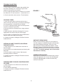
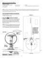
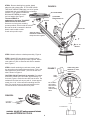
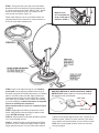
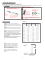
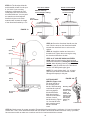
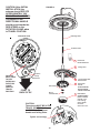
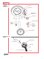
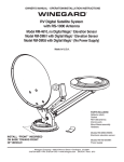
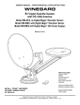
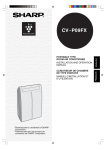
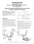
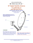
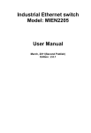
OWNER’S MANUAL - OPERATION/INSTALLATION INSTRUCTIONS
®
WINEGARD
RV Digital Satellite System
with RS-1000 Antenna
Model RM-4610, no Digital Magic Elevation Sensor
Model RM-DM61 with “Digital Magic” Elevation Sensor
Model RM-DM55 with “Digital Magic” (No Power Supply)
TM
TM
TM
U.S. PATENT NO. 5,532,710 AND 5,554,998
Made in U.S.A.
PARTS INCLUDED:
Reflector (dish)
Gasket
RS-1000 antenna
Interior parts
Mount/base assembly
Hardware
Models RM-DM61/DM55
Electronic elevation sensor
INSTALL “FRONT” INSCRIBED
ON BASE TOWARD FRONT
OF VEHICLE!
Models RM-4610/DM61
Power supply
Winegard Company • 3000 Kirkwood Street • Burlington, IA 52601
319/754-0600 • FAX 319/754-0787 • www.winegard.com Rev. 6/09/03
1
OPERATION
FINDING THE SATELLITE
TUNING ANTENNA FOR THE BEST PICTURE
STEP 1. Your receiver should indicate it is receiving a
signal. To tune your antenna, slowly move the antenna
left, then right, until you find the position with the highest
signal strength. It is important to turn the antenna
slowly. Because the signal is digital, it takes a few
seconds for the receiver to lock on.
STEP 2. Place rotation clamp in the LOCK position.
This prevents the antenna from moving and losing
signal.
STEP 3. Slowly raise, then lower the antenna until you
have “peaked” the signal (found the strongest signal).
ELEVATION
TURNS CW
o
14 - 16
14
17 - 19o
14-1/2
20 - 22o
15
o
23 - 25
15-1/2
o
26 - 29
16
30 - 32o
16-1/2
33 - 35o
17
o
36 - 38
17-1/2
o
39 - 42
18
43 - 45o
18-1/2
46 - 48o
19
o
49 - 51
19-1/2
o
52 - 54
20
55 - 57o
20-1/2
58 - 61o
21
o
62 - 64
21-1/2
65 -67°
22
68 - 70°
22-1/2
71-73°
23
STEP 1. Step outside the vehicle and, using a compass,
determine which direction is North. (Standing in or near
the vehicle can give you an incorrect reading.) The more
accurately you determine North, the easier it will be to
find the satellite(s).
STEP 2. Using satellite receiver, determine correct
elevation for your location. See your receiver manual for
setup information.
STEP 3. Press button on Winegard Digital Display wall
plate. If the antenna is in travel position, the display will
show LL for Low Limit. HL for High Limit will show when
dish is in Up position.
STEP 4. Crank elevation handle to raise antenna. Stop
cranking when readout displays the correct elevation for
your location.
STEP 5. Rotate antenna VERY SLOWLY until correct
satellite signal is acquired. NOTE: Rotate 3° and then
stop. DO NOT rotate continuously, even if you are
rotating slowly. If you notice the elevation angle has
changed, it may be due to the following reasons:
a. RV is not parked level.
b. Antenna system is mounted to a slightly sloped
RV roof. (This is not a problem. When you have
rotated the antenna so it is facing in approximately the right azimuth [compass direction],
simply adjust to correct elevation and continue
searching for the satellite signal.)
Special notes: When you have detected the satellite
signal, adjust the antenna up/down and left/right for the
strongest signal your receiver displays. Because of
differences in receivers and installation methods, you
may find the elevation numbers, after peaking on the
strongest signal, no longer match what the receiver
recommended. This is normal. The elevation sensor
should always get you close enough to find a signal to
peak on. If display turns off while you’re searching, just
push button for another minute of operation. After a little
practice, most people can find the signal in 30 to 50
seconds.
WATCHING OFF-AIR TV
To watch the area (local) television programming, use
one of these options —
• Use an A-B switch between the receiver and antenna
power supply.
• Use a video switch, Figure 1.
• Connect antenna output from power supply to TV
ANTENNA input on receiver, Figure 2. When you turn
off the receiver, it automatically switches you to off-air.
TROUBLESHOOTING
• If digital display reads EE, check wiring and connection. If wiring and connections are not correct at installation, operation is affected.
• Remember to rotate antenna VERY SLOWLY until
correct satellite signal is acquired.
LOWERING ANTENNA TO TRAVEL POSITION
STEP 1. Set rotation clamp to ROTATE position.
STEP 2. Fully rotate antenna counterclockwise until
pointer on directional handle aligns with red screw on
rotation clamp.
STEP 3. Turn elevating crank counterclockwise in
direction of “DOWN” arrow until resistance is met.
The number of turns will vary according to the elevation
angle the antenna was set to.
STEP
4. MoveUnder
rotationno
clamp
to the LOCK position.
CAUTION:
circumstances
DISPLAY CODES
HL ................. High Limit
LL .................. Low Limit
Lo .................. Battery Low
Er .................. Communication Error
— — ............... Initializing
NOTE: Initialization may take up to 5 seconds.
2
lower the antenna to any position
other than travel position!
OPERATIONS DO’S AND DON’T’S
DO’S
1. Do check parking location for obstructions before
raising antenna.
DON’T’S
1. Don’t move RV/Coach with the antenna in the UP
position. This will VOID your warranty. This may
also cause damage to your roof.
2. Do carefully raise, lower and rotate the antenna — if
difficult, check for cause.
2. Don’t force the elevating crank up or down. Check for
the cause.
3. Do rotate slowly when searching for the satellite(s)
and check fine tuning on TV set for proper adjustment.
3. Don’t rotate directional handle hard against stops.
4. Do lower antenna before moving vehicle.
4. Don’t apply paint on top of base plate or anywhere on
the lift.
5. Activate programming by calling programming
provider for your receiver.
5. Don’t apply approved sealing compound on gear
housing.
SUGGESTED SETUPS
FOR MULTIPLE TVS
FIGURE 1
FIGURE 2
3
TROUBLE SHOOTING
NO PICTURE ON TV
1. Do you have a clear line of sight to the satellite? Are
there trees, buildings, etc. in the way? Figure 3 illustrates the look angle of your reflector.
FIGURE 3
2. Do you have the menu from the receiver? If not, check
the channel the TV set is tuned for — it should be 3 or 4.
Reflector at 90°
3. Check connections at the receiver, TV and antenna.
Sig
NO SIGNAL FOUND
1. Have you entered the correct zip code into the receiver? If the zip code is wrong, you may be searching in
the wrong direction or elevation for the satellite.
na
l fr
om
sa
tel
lite
24°look angle
2. Is your TV working properly? Does it receive pictures
from off-air stations or your VCR?
LNBF
3. Re-tune system for the best picture, using procedure
on page 2.
4. Inspect antenna. Has it been damaged? If it is even
slightly bent, the receiver may not receive signal.
5. Do you have +12 VDC at the end of the LNBF cable?
Remove cable from LNBF before testing.
6. Contact your dealer or Winegard Technical Services
at 800/788-4417.
WARRANTY REPAIR WORK
Before you have warranty repairs on your system, be
sure the company or individual doing the work has been
approved by Winegard Company. If there is not an
approved repair company/individual available, contact
Winegard Company at 800/288-8094 before proceeding.
The Winegard Warranty covers only the mount, antenna
and LNBF. For receiver warranty, refer to the receiver
manufacturer’s warranty.
ANTENNA IS HARD TO ROTATE, OR ANTENNA
DOES NOT ROTATE
1. Inspect antenna on roof. Make sure mount has not
been damaged.
2. Be sure there is no sealant between gear housing and
base plate.
4. Be sure cable is routed correctly. Cable may be
preventing rotation of antenna.
ORDERING REPAIR PARTS
Repair parts are available at RV dealers and/or service
centers throughout the U.S. Or you can call Winegard
Company at 800/288-8094. Credit card orders only,
minimum order $5.00.
3. Contact your dealer or Winegard Technical Services
at 800/788-4417.
ANTENNAS HARD TO RAISE, OR ANTENNA DOES
NOT RAISE
1. Inspect antenna on roof. Be sure he mount has not
been damaged.
2. Is the antenna obstructed?
3. Contact your dealer or Winegard Technical Services
at 800/788-4417.
4
INSTALLATION AND ASSEMBLY
THINGS YOU NEED
Screwdrivers (Phillips and slot)
1-3/4” hole saw
7/16” wrench
Drill with 1/8” bit
Tape measure
Sealant
(Must be approved for compatibility w/roof)
STEP 1. Choose a location on the roof for the unit. The dish must be able to rotate without interfering with other roofmounted equipment (air conditioners, etc.), Figure 4. Be sure the interior ceiling plate is easily accessible with no obstructions that may interfere with operation.
NOTE: Check with your dealer or vehicle manufacturer for features that may have been installed for
antenna mounting — reinforced roof areas or pre-wire
installation done at the factory.
FIGURE 4
THE SYSTEM MUST BE LEVEL FOR PROPER
OPERATION! Winegard’s RW-5000 roof wedge is
available for sloped roofs, Figure 5. If using roof wedge,
installer will provide longer mounting screws. Mount
base plate and ceiling plate must be parallel with
each other, Figure 5. If shims or wedges are used, the
installer must supply.
STEP 2. Position roof template (inserted in this manual)
on the roof. CAUTION: DO NOT drill through wiring.
Carefully drill a 1-3/4” hole through roof and ceiling of
vehicle. Inspect hole to make sure wiring is intact.
FIGURE 5
Mount base plate and ceiling plate must be parellel with each
other. if shims or wedges are needed, installer must supply.
5
STEP 3. Remove backing from gasket. Attach
adhesive side to base plate. IF YOU ARE USING
THE ROOF WEDGE (RW-5000), use 3/16” gasket
included with the mount UNDER the roof wedge.
Install the 1/16” gasket included with
RW-5000 BETWEEN the mount
and roof wedge.See Figure 7.
The word FRONT is
embossed on the base. This MUST
FACE the front of the vehicle.
Secure to roof using two mounting
PINS
screws provided. Check inside the vehicle.
Be sure the shaft is centered in the hole.
Attach crank handle to shaft.
Crank unit up until it stops.
FIGURE 6
RS-1000 ANTENNA
(4) ANTENNA
MOUNTING BOLTS
E-CLIPS
REFLECTOR
Attach RS-1000 to
ELEVATING TUBES using
E-Clips and Pins supplied.
(4) 1/4 - 20
HEX NUT
STEP 4. Attach reflector to backup assembly, Figure 6.
STEP 5. Attach RS-1000 antenna to elevating tubes.
Use the two E-clips and pins provided, Figure 6. Attach
coax cable to F-jack on antenna and slide on weather
boot, Figure 6.
STEP 6. Install remaining mount base screws. Install
the vent tube on the back of the mount base. (This is the
side opposite the word FRONT.) The hole for the vent
tube is shown in Figure 8.
Cable-entry plate
Minimum 3” from
mount base
FIGURE 7
CAUTION: DO NOT seal hole in vent tube. Put sealant
around the outside of the vent tube, approximately 1/2”
from end, Figure 8. Push the vent tube into the hole. The
sealant will seal the hole as you push in. Leave approximately 2 to 2-1/2” of the vent tube extending from the
hole. Put a small amount of approved sealant on the
roof and under the vent tube to hold in place.
Cable
clamp
Do not attach
cable clamp
with screw to
base plate
until installing
cable.
FIGURE 8
Base plate
6-1/8”
Travel Bracket
6
STEP 7. Facing the front of the dish, find coax cables
attached to side of the feed arm, Figure 9. Measure 24”
of coax from this point and mark. DO NOT CUT. Rotate
mount on base clockwise, fully, until it stops. Route
coax around mount base, Figure 10.
FIGURE 9
Measure coax
24” from plastic tie
wrap on left side of
feed arm. (STEP 7)
Fasten cable clamp in hole in mount base (check roof
template inserted in this manual for correct location) at
end of the coax cable measurement.
FIGURE 10
STEP 8. Feed coax cables through the roof. Weatherproof cable entry by applying sealant under the lip of
the cable-entry plate and where cable enters roof. Attach
plate to roof with screws provided. Apply sealant over
screws and around edge of roof-through plate, making
sure cable entry is sealed. Secure cables as necessary
to prevent whipping. If cable connections are exposed,
be sure to weatherproof connection!
Mount travel bracket to roof 6-1/8” from base, Figure
7, page 6.
STEP 9. Apply approved sealing compound to screw
heads, cable entrance hole and edge of gasket under
mount, AFTER mounting, Figure 7.
STEP 10. Attach satellite coax cable (with RG-6 printed
on it) to the satellite receiver.
STEP 11. Attach RS-1000 coax downlead (with RG-59
printed on it) to RV-7542 power supply. Refer to power
supply instruction sheet. You can connect the antenna
ANOTHER METHOD OF INSTALLING ROOF CABLE/
ENTRY PLATE: Attach cable to roof using cable clamp.
Use sealant to seal screw heads.
Cable clamp
Cable
Cable entry plate
output from the power spply directly to the “TV ANT IN” on
satellite receiver. (Refer to receiver manual.) This allows
you to watch local channels when you turn off the receiver.
STEP 12. Connect digital elevation sensor at roof level,
see top of page 8.
7
FOR RM-DM61/RM-DM55 ONLY
DIGITAL ELEVATION SENSOR ROOF CONNECTIONS
The illustrations below show the different methods of connecting wires at roof level. Method will depend on model. Wire
colors MUST MATCH (i.e. red to red, green to green, black to black, white to white).
Snap
connectors
together
NOTE: This terminal is NOT
weatherproof and CANNOT be
left outside on the roof.
INSIDE YOUR RV
Supplied with the DM-2000 only.
Squeeze pliers until red
plunger is flush with
rest of terminal.
3M UR Terminal
Slide wires all
the way in.
DO NOT strip
wires, terminal
is self stripping.
Pliers not supplied
NOTE: This terminal is weatherproof and can be left outside on
the roof as LONG AS IT IS SECURED PROPERLY to prevent
whipping in the wind.
FIGURE 11
STEP 13. Place the nut on the threaded rod.
Roof
Thickness
STEP 14. Measure and cut the threaded rod with a
hacksaw. Use the chart, Figure 11, to determine the
length.
Directional
Handle Length
(Figure 3E)
Threaded
Rod Length
Worm Gear
Shaft Length
(Figure 3G)
1-1/2” .............. 2-7/8” ................. 2-3/4” ............... 2-7/8”
1-3/4” .............. 3-1/4” ................. 3” ...................... 3-1/8”
2” ..................... 3-1/2” ................. 3-1/4” ............... 3-1/2”
2-1/4” .............. 3-7/8 ................... 3-1/2” ............... 3-7/8”
2-1/2” .............. 4-1/8” ................. 3-3/4” ............... 4-1/8”
2-3/4” .............. 4-1/2” ................. 4” ...................... 4-1/2”
3” ..................... 4-3/4” ................. 4-1/4” ............... 4-3/4”
3-1/4” .............. 5” ........................ 4-5/8” ............... 4-7/8”
3-1/2” .............. 5-1/4” ................. 4-7/8” ............... 5-1/8”
3-3/4” .............. 5-5/8” ................. 5-1/4” ............... 5-1/2”
4” ..................... 5-3/4” ................. 5-1/2” ............... 5-3/4”
4-1/4” .............. 6-1/8” ................. 6” ...................... 6-1/8”
4-3/4” .............. 6-5/8” ................. 6-1/8” ............... 6-3/8”
5” ..................... 6-7/8” ................. 6-3/8” ............... 6-5/8”
5-1/4” .............. 7-1/8” ................. 6-5/8” ............... 7”
5-1/2” .............. 7-3/8” ................. 6-7/8” ............... 7-1/4”
STEP 15. Remove the nut over the cut end of the
threaded rod. This cleans the threads after cutting.
STEP 16. Thread the cut end of the rod into the hub,
STEP 17. Install the ceiling plate. The rotate/lock
lever must point toward the rear of the vehicle.
Be sure rotate/lock lever is pointing toward back
of vehicle and hole in ceiling aligns with hole in
the ceiling plate.
NOTE: Make sure large and small keyways line
up in the hub and directional handle!
STEP 18. Measure and cut the directional
handle; see Figure 12 and chart, Figure 11.
NOTE: A tube cutter is recommended for
cutting the directional handle. This gives a
square cut; a hacksaw does not. If using an
extension, see Step 22, page 9.
FIGURE 12
³
This wire harness connects to the digital
elevation sensor on the antenna.
HANDLE
LENGTH
Figure 13, page 9, shows what points to
measure between, with and without a roof
wedge.
8
³
DIRECTIONAL
HANDLE
WITH ROOF WEDGE
WITHOUT ROOF WEDGE
Measure from top
of roof wedge to ceiling.
TOP OF
ROOF WEDGE
Measure from top
of roof to ceiling.
³
TOP OF
ROOF
³
STEP 19. The directional handle
and threaded rod will fit roofs up to
5-1/4" thick. If you are using
wedges to compensate for roof/
ceiling slope, be sure to allow for
this extra thickness. You may add
an extension to the directional
handle for thicker roofs. Each
extension will increase the length
of the directional handle by 2-1/4".
FIGURE 13
CEILING
³
³
CEILING
FIGURE 14
STEP 20. Press the directional handle onto the
hub. Point the arrow on the directional handle
towards the rotate/lock lever to orient to the
splines.
Plastic
Plug
Spacer
STEP 21. Install the washer and nut on the
threaded rod. Tighten the nut enough to snug
the directional handle to the hub.
Spring
STEP 22. IF YOU ARE USING AN EXTENSION, adjust the total length of the directional
handle and extension by cutting the directional
handle. After adjusting parts for proper roof
thickness, glue the extension to the directional
handle. Use ABS (plastic pipe) glue.
Hub
Worm
Gear
NOTE: For roofs thicker that 5-1/4", a longer
aluminum hex shaft will be needed. Contact
Winegard Company for this part.
Threaded
Rod
Ceiling
Plate
CUTTING SHAFT
LENGTH, Figure 14A:
Flip down handle on
the elevating crank
handle. Slide elevating
crank handle up shaft
until snug against
directional handle.
Mark the elevating
shaft at inside bottom
surface of crank
handle housing, Figure
12. Cut shaft at mark,
after removing crank
handle. Reinstall
crank.
Directional
Handle
FIGURE 14A
Elevating shaft
Cut elevating
shaft at inside
surface of
crank handle
housing; shaft
goes through
hex-shaped
opening by
screw.
Crank Handle
STEP 23. Check system for proper operation. Elevate dish with crank handle. A minimum of 14 turns is needed to
elevate dish. Then, move directional handle with dish elevated. Directional handle should turn freely. If possible,
have someone watch to make sure coax does not bind or interfere with dish movement.
9
CAUTION: After INITIAL
INSTALLATION, the
antenna should ROTATE
APPROXIMATELY 360°
FROM TRAVEL POSITION.
FIGURE 15
The pointer on the
DIRECTIONAL HANDLE
should point towards the
RED SCREW on the
ROTATION CLAMP when
in TRAVEL POSITION.
ASSEMBLED VIEW
Elevating Shaft
Threaded Tube
POINTER
MUST POINT
TO RED
SCREW ON
ROTATION
CLAMP
WHEN IN
TRAVEL
POSITION
3
Directional
Handle Extension
1
Ceiling Plate
2
(4) #10 Phillips Flat
Head Screws
4
Directional
Handle
Rotation
Clamp
Red Screw
Flat Washer
POINT TO
BACK OF RV
Nut for
threaded tube
CAUTION:
The antenna MUST BE IN THE
TRAVEL POSITION before
ALIGNING the Directional
Handle and Ceiling Plate.
Tighten screw snugly
10
ALIGN POINTER
WITH ANTENNA
TRAVEL POSITION
5
ELEVATING
CRANK HANDLE
(When installed,
extends 2-1/4"
from ceiling).
Snap Handle
into base
when not in use.
4/22/02
11
Feed Arm
Interior
Wall Plate
Display Unit
Roller
Hex Head Bolt 1/4-20 x 2.5”
Nylock Nut 1/4-20
(not shown)
Bottom Boom
Bushing
Screw
Rubber Bumper
Mount Adapter
Pin 1-9/16” long
LB-1000: Standard
Single LNBF
E-Clip
1-7/16”Long Pin (3)
Lift Link (2)
Pivot Bracket
(Feed Arm)
Travel Bracket
Flange Nut
1/4-20
Carriage Bolt
Top Boom
E-Clip
Antenna Head
(4) Flat Head Bolts
(White)
Pivot Bracket
(Tubes)
Turret Top
Cable Entry
Plate
INCLUDED BUT NOT SHOWN
LNBF Coax
RG-6 (20’)
Antenna Head Coax
RG-59 (25’)
Travel Support Bracket
Screw # 10-24 x 3/4 (4)
Clamp (2)
Screw, 1/4-20 x 5”
Nylock Nut, 1/4-20
E-clip
Pin, 1/4 x 3.25” long
E-clip for 1/4” Pin
Dish Frame
Digital Elevation Unit
46 cm Reflector
White
EXPLODED PARTS VIEW
PARTS LIST
INTERIOR
HARDWARE KIT
RK-CEIL
Ceiling Base
Directional Dial
(4) #10 Phillips Flat
Head Screws
Azimuth Lock
Azimuth Lock Knob
Directional
Handle
Extension
Washer
#10 x 3/8"
Red Phillips
Screw
Directional Handle
CRANK HANDLE KIT
RK-HAND
#8-32 x 3/8"
Phillips Screw
Crank Handle Base
#8-32 Square Nut
Crank Handle
Knob
#10 x 3/8" Phillips Screw
Washer
NOT TO SCALE
Rev 6/11/01
12
SPECIFICATIONS
Height when raised ........ 30” with satellite antenna in vertical position
Height in travel position ........ 8”
Operating radius ........ 35” (70” diameter circle)
Roof space required ........ 19.5” x 46.75”
LNBF ........ Compatible with DISH Network®, DirecTV® and ExpressVu
Color ........ White
Satellite antenna height ........ 20.9”
Satellite antenna width ........ 19.5”
F/D ........ 0.59
Offset angle ........ 24°
Satellite antenna gain—
11.2 GHz ........ 33.22 dBi
12.1 GHz ........ 33.89 dBi
12.6 GHz ........ 34.23 dBi
Aperture efficiency ........ 73%
Cross polarization (on axis) ........ -21 dB
*Beamwidth at -3 dB ........ 3.5°
*Beamwidth at -10 dB ........ 7.0°
RS-1000 antenna gain —
VHF ........ 15.5 dB average
UHF ........ 19.5 dB average
RS-1000 antenna height ........ 3.25”
RS-1000 antenna width ........ 14.5”
Wind Loading ........ Up to hurricane force
Weight ........ 19 lbs. maximum
Shipping weight ........ 21 lbs.
ANTENNA/LIFT/LNBF TWO YEAR LIMITED WARRANTY
Winegard Company warrants this Winegard product (excluding receiver) against any defects in materials or
workmanship within two (2) yeares from date of purchase. No warranty claim will be honored unless at the time the claim
is made, you present proof of purchase to an authorized Winegard dealer (if unknown, please contact Winegard
Company, 3000 Kirkwood Street, Burlington, Iowa 52601-2000, telephone 319-754-0600).
Winegard Company (at its option) will either repair or replace the defective product at no charge to you. This warranty
covers parts, but does not cover any costs incurred in removal, shipping or reinstallation of the product. This limited
warranty does not apply if the product is damaged, deteriorates, malfunctions or fails from: misuse, improper
installation, abuse, neglect, accident, tampering, modification of the product as originally manufactured by Winegard,
usage not in accordance with product instructions or acts of nature such as damage caused by wind, lightning, ice or
corrosive environments such as salt spray and acid rain.
The Two Year Warranty is provided on the condition that the equipment is properly delivered with all handling and
freight charges prepaid to your Winegard dealer for repair or return to our factory at the above address. Winegard
dealers will arrange for the replacement or repair and return to you, without charge, the product which failed due to
defective material or workmanship.
WINEGARD COMPANY WILL NOT ASSUME ANY LIABILITIES FOR ANY OTHER WARRANTIES, EXPRESS OR
IMPLIED, MADE BY ANY OTHER PERSON.
ALL OTHER WARRANTIES WHETHER EXPRESS, IMPLIED OR STATUTORY INCLUDING WARRANTIES OF
FITNESS FOR A PARTICULAR PURPOSE AND MERCHANTABILITY ARE LIMITED TO THE TWO YEAR PERIOD
OF THIS WRITTEN WARRANTY.
The foregoing shall be the sole and exclusive remedy of any person whether in contract, tort or otherwise, and
Winegard shall not be liable for incidental or consequential damage or commercial loss, or from any other loss or
damage except as set forth above.
Some states do not allow limitations on how long an implied warranty lasts, or the exclusion of limitation of incidental
or consequential damages, so the above limitations or exclusions may not apply to you.
This warranty gives you specific legal rights and you may also have other rights which vary from state to state.
13
REPLACEMENT PARTS KITS
HEAD ASSEMBLY RP-RS00
Head w/bracket and nut ................ 1
Pins .............................................. 2
E-Clip ............................................ 2
TURRET ASSEMBLY RP-9500
Spring ........................................... 1
Roll Pin ......................................... 1
Gear for worm shaft ...................... 1
Elevation gear .............................. 1
Bushing ........................................ 2
Seal .............................................. 2
O-ring ........................................... 1
Clamp ........................................... 2
Shaft ............................................. 1
Bearing, outer ............................... 1
Bearing, inner ............................... 1
Worm gear on shaft ...................... 1
Turret top ...................................... 1
Turret base ................................... 1
Turret hub ..................................... 1
Plug .............................................. 1
Plate rotate limit ............................ 1
Screw ........................................... 2
Gasket .......................................... 1
Bracket ......................................... 1
Screw ........................................... 2
Pin ................................................ 2
E-Clip ............................................ 2
Pivot Bracket ................................ 1
REFLECTOR RP-REFL
Dish .............................................. 1
Bolt ............................................... 4
Nut ................................................ 4
BOOM ASSEMBLY RP-BOOM
Top boom ..................................... 1
Bottom boom ................................ 1
Bumper ......................................... 1
Screw ........................................... 1
Bushing ........................................ 1
Lift link .......................................... 2
Pin ................................................ 3
E-Clip ............................................ 4
Nut ................................................ 2
Screw ........................................... 1
Pivot bracket ................................. 1
Long bolt ....................................... 1
Nylock nuts ................................... 2
GEAR KIT RP-GEAR
Elevation gear (RMs) .................... 1
Elevation gear (RVs & RDs) ......... 1
Plug .............................................. 1
O-ring ........................................... 1
RD MODELS Wave washer ................................ 1
Quad ring ...................................... 1
Flat washer ................................... 1
Washer ......................................... 1
Extension ...................................... 1
Worm gear, 16” shaft .................... 1
Seal .............................................. 2
Bushing ........................................ 2
BACKUP & FEED ASSEMBLY RP-BUFA
Fram ............................................. 1
Feed arm ...................................... 1
Roller ............................................ 1
Bolt ............................................... 1
Nut ................................................ 3
Bracket ......................................... 1
Pin ................................................ 2
E-Clip ............................................ 3
Screw ........................................... 1
Spring ........................................... 1
Clamp ........................................... 1
Screw ........................................... 4
14
15
Printed in U.S.A. Winegard Company • 3000 Kirkwood Street • Burlington, Iowa 52601 © Winegard Company, 2002 2451070 Rev. 6/09/03
16