1
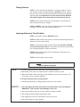
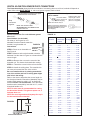
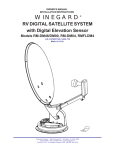
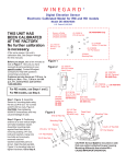
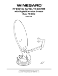
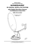
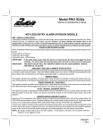
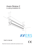
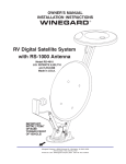
®
RV DIGITAL SATELLITE SYSTEM
with Digital Elevation Sensor
Model RM-DM46
may also be packaged as
RM-DM00, RMDM04, RMFLDM4
U.S. Patent Number 5,532,710
Made in U.S.A.
Winegard Company • 3000 Kirkwood St. • Burlington, IA 52601-2000
319/754-0600 • FAX 319/754-0787 • www. winegard.com
Printed in U.S.A. © Winegard Company 2002, 2005 2451069 Rev. 12/05
1
Operation
STEP 1. The more accurately you determine North, the easier it is to locate the satellite. Step
outside and away from your vehicle. (Standing to near your vehicle can give incorrect
compass readings.) It is helpful if there is a landmark on the horizon to represent North. Return
to the vehicle and point the Directional Dial North, or to the landmark.
DIRECTIONAL
HANDLE
ELEVATIING CRANK
DIRECTIONAL DIAL
DIRECTIONAL HANDLE
POIINTER
FIGURE 1
RED SCREW
ROTATION CLAMP
STEP 2. Turn on receiver and television. Tune the television to channel 3 or 4. Using your receiver manual for
instructions, go to the Signal Meter screen. Enter nearest Zip code for your location using receiver’s remote
control. After the Zip code is entered, the receiver will indicate numbers for Azimuth (compass heading) and
Elevation. See chart below to determine number of turns needed for each elevation. Turn the elevation
handle CLOCKWISE to raise the antenna. Turn the elevation handle COUNTERCLOCKWISE to lower the
antenna.
STEP 3. Press button on Winegard Digital Display Wall plate. If antenna is in travel position, the display will
show LL for Low Limit. HL for High Limit will appear when dish is in up position.
STEP 4. Crank elevation handle to raise antenna. Stop cranking when readout displays correct elevation for
your location, found on the receiver’s signal meter screen.
STEP 5. Rotate antenna VERY SLOWLY until correct satellite signal is acquired. NOTE: Rotate 3°, then stop.
DO NOT rotate continuously, even if you are rotating slowly. If you notice the elevation angle has changed, it
could be due to the following reasons:
1. RV is not parked level.
2. Antenna system is mounted to a slightly sloped RV roof. (This is not a problem. When you have
rotated the antenna so it is facing in approximately the right azimuth [compass direction], simply
adjust to correct elevation and continue searching for signal.
Special Notes: When you have detected the satellite signal, adjust the antenna up/down and left/right for the
strongest signal the receiver displays. Due to variations in receivers and installation methods, you may find the
elevation numbers, after peaking on the strongest signal, no longer match what the receiver recommended.
This is normal. The elevation sensor should always get you close enough to pick up a signal to peak on. If the
display turns off while you’re searching, just push button for another minute of operation. After a little practice,
most people find the signal in 30 to 50 seconds.
Replacement Parts
For replacement parts, contact Winegard Company.
Customer Service. Hours are 7:00 a.m. to 5:00 p.m., Monday through Thursday, and 7:00 a.m, to 4:00 p.m. Friday
Central Time. Call toll-free 1-800-288-8094. Credit card orders only, $5.00 minimum order.
2
Rev. 7/9/04
Tuning Antenna
STEP 1. Your receiver should indicate it is receiving a signal. To tune
your antenna for the best signal strength. SLOWLY move the antenna
left, then right, until you have found the position that gives the highest
signal strength. It is important to turn the antenna slowly. Because
the signal is digital, the receiver takes a few seconds to lock on.
STEP 2. Place rotation clamp in the LOCK position. This prevents an
tenna movement and loss of signal.
STEP 3. SLOWLY raise, then lower the antenna until you have peaked
the signal. You are now ready to watch satellite TV!
Lowering Antenna to Travel Position
STEP 1. Set rotation clamp to ROTATE position.
STEP 2. Rotate antenna until pointer on directional handle aligns with the
red screw on the rotation clamp.
STEP 3. Turn elevating crank counter clockwise in direction of DOWN
arrow until meeting resistance. The number of turns will vary according
to the elevation angle the antenna was set at.
STEP 4. Move rotation clamp to the LOCK position. Antenna is now
locked in travel position.
STEP 5. Snap elevation crank in place.
CAUTION! NEVER LOWER ANTENNA IN ANY POSITION
EXCEPT TRAVEL POSITION!
DO’S
1. Do check parking location for obstructions before raising antenna.
2. Do carefully raise, lower and rotate antenna. If difficult, check for cause.
3. Do rotate SLOWLY when searching for the satellite(s), and check fine tuning on TV
set to make sure it is properly adjusted.
4. Do lower antenna before moving vehicle!
5. Activate programming by calling program provider for your receiver.
DON’T’S
1. Don’t move RV/coach with the antenna in the UP position. This will VOID your
WARRANTY. This may also cause damage to your roof.
2. Don’t force elevating crank up or down. Check for cause of trouble.
3. Don’t rotate directional handle hard against stops.
4. Don’t apply paint over top of base plate or any where on lift.
5. Don’t apply sealant on gear housing.
3
Trouble Shooting
Antenna Reflector at 90°
Sig
na
l fr
om
sa
tel
24° look angle
LNBF
FIGURE 2
lite
1. You may need to roatate the dish in small increments to find the signal.
Rotate the dish 3° at a time to the left, stopping for a few seconds each
time you move the dish. Try moving the dish up to 20° to the left. If no
signal is found, return to the azimuth listed and and try rotating 20° to the right.
This will help correct for any errors in setting the directional handle.
2. Be sure you have a clear line of sight. The signal from the satellite(s)
WILL NOT pass through trees, buildings, mountains, etc. Remember the
antenna has a 24° offset, this means that when the antenna is straight
up and down, (90°) it is looking 24° into the sky. See Figure 2.
3. Do you have the TV set tuned for the correct channel 3 or 4 (same
channel as output of receiver)?
4. Have you entered the correct zip for the area you are currently in?
If the zip code is wrong, the antenna will be looking in the wrong
direction or at the wrong elevation for the satellite signal you want.
5. Check connections at the receiver, TV, and antenna.
6. Check the TV. Does it receive pictures from off-air television stations/VCR?
7. Retune system for best picture,using procedure on page 3.
8. Inspect antenna. Make sure it has not been damaged. If the antenna
is even slightly bent, the receiver may not receive the signal.
9. Contact Dealer or Winegard Service Department.
ANTENNA DOES NOT ROTATE, OR IS HARD TO ROTATE
1. Inspect antenna on roof. Be sure the mount has not been damaged.
2. Check for caulking between gear housing and baseplate.
3. Be sure cables are not binding, and that they are installed properly.
4. Contact your dealer or Winegard Technical Services.
ANTENNA DOES NOT RAISE, OR IS HARD TO RAISE
1. Inspect antenna on roof. Be sure the mount has not been damaged.
2. Check for caulking on elevating shaft.
3. Contact your dealer or Winegard Technical Services.
LCD DISPLAY CODES
HL ................ High Limit
LL .................. Low Limit
Lo ................ Batter Low
Er ......................... Error
-- .................. Initializing
NOTE: Initialization may take up to 5 seconds.
7/09/04
4
Assembly & Installation
Things you need —
Screwdrivers (Phillips and slot)
1-3/4” hole saw
7/16” wrench
Non-hardening sealant
(Check manufacturer’s specifications for
compatibility with your roof material.)
ABS glue
Drill with 1/8” bit
Tape measure
Winegard’s Digital Elevation Sensor has been
INSTALLED and CALIBRATED at the factory
STEP 1. Choose a location on the roof for dish that will allow dish to raise and rotate without
FIGURE 3
interfering with other roof-mounted equipment. Make sure inside ceiling plate is easily accessible, and with no obstructions that would interfere with operation.
Figure 3 shows minimum distance (10”) antenna should be located from edge
of vehicle roof. It is recommended that you check with your dealer or manufacturer
for provisions that may have been made in the roof for antenna mounting; a
reinforced roof area or pre-wire installation
from the factory.
The system must be level for
proper operation! Winegard Model
NOTE:
RW-5000 roof wedge with gasket is available. If
inside roof wedge is needed, Winegard’s
RW-2000 can be trimmed to fit ceiling plate.
Center Roof Line
STEP 2. Position template on roof (see insert page of
this manual). CAUTION: DO NOT drill through
wiring. Carefully drill a 1-3/4” hole through roof and
ceiling of vehicle. Inspect hole to make sure wiring
is intact. (Roof template, see insert.)
It is highly recommended the antenna be
mounted on roof center line. Do not mount
antenna closer than 10” from roof edge.
19.50”
34” DIAMETER
OPERATING
AREA
29”
RW-5000
Roof Wedge
with gasket
Vehicle Roof
17” RADIUS
MINIMUM
10”
Antenna Controls
NOT TO SCALE
FRONT OF VEHCILE
5
Interior
Roof Wedge
(Optional)
Rev/7/9/04
STEP 3. Attach dish to backup. Use bolts and
nuts provided, Figure 4.
(4) Antenna
Mounting Bolts
STEP 4. Mount dish on roof in upright position. Rotate
clockwise to stop, Figure 5. Dish will be toward back
of vehicle when in stowed or travel position. The word
FRONT is embossed on the base and should face the
front of vehicle. Secure to roof using screws (provided).
The travel bracket sjhould be mounted to roof 6-1/8”
from base of dish, toward back of vehicle. See Figure 6.
NOTE: Apply non-hardening sealing compound to
screw heads, coax access hole and edge of gasket
under mount base.
Install the vent tube on the back of the mount base
(the is the side opposite the word FRONT). The hole
for the vent tube is shown in Figure 6A. CAUTION:
DO NOT seal hole in vent tube. Put sealant around
the outside of the vent tube, approximately 1/2” from
end. Push vent tube into the hole. The sealant will
seal the hole as you push in vent tube. Leave approximately 2 to 2-1/2” of the vent tube extending from the
hole. Put a small amount of sealant on the roof under
the vent tube end to hold in place.
FIGURE 4
(4) 1/4-20
HEX NUTS
FIGURE 5
Rotate
clockwise
to stop.
Measure 24” of coax
at plastic fastener on
left side of feed arm.
(See Step 5.)
FIGURE 6
Base Plate
No cable clamps on
this part of cable.
Install cable entry plate 3”
minimum from mount base.
FIGURE 6A
ANOTHER METHOD OF IBSTALLING ROOF/CABLE
ENTRY PLATE: Attach cable to roof using cable clamp.
Use sealant to seal screw heads.
CAUTION: DO NOT GET sealing compound
between Base Plate and Rotating Gear
Housing. DO NOT PAINT top of Base Plate or
around Rotating Gear Housing.
STEP 5. Facing the front of the dish, note the coax
attached to the side of the feed arm. Meaure 24” coax
from this point. DO NOT CUT. Put coax around mount
base, Figure 5.
STEP 6. Apply approved sealing compound over
mounting screw heads.
#10 x 1” Screws
FIGURE 7
STEP 7. Feed coax through the roof using cover plate
(included, w/hardware), Figure 7. Weatherproof cable
entry by applying sealant under lip of cable entry plate
and where cable enters roof. Attach plate to roof with
screws provided. Apply sealant over screws and
around edge of roof-thru plate, making sure cable entry is sealed. If downlead connection is made on
top of roof, make sure to weatherproof connection!
Rev. 6/06/03
CE-2000
Downlead
Downlead
connects to
satellite receiver
6
FS-8100
Male-to-male
F-connector
DIGITAL ELEVATION SENSOR ROOF CONNECTIONS
The illustrations below show the different methods of connecting wires at roof level; method will depend on
model. Wire colors MUST MATCH, ie. red to red, green to green, black to black.
This wire harness connects to the digital
elevation sensor on the antenna
Snap
connectors
together
Supplied with DM-2000 only
3M UR TERMINAL
DO NOT STRIP
wires, terminal is
self-stripping.
Slide wires all the way in.
Squeeze pliers until
red plunger is flush
with res of terminal.
(Pliers not supplied.)
NOTE: This terminal is weatherproof
and can be left outside on the roof IF
SECURED PROPERLY to prevent
wind whipping.
NOTE: This terminal is NOT
WEATHERPROOF and CANNOT be left
outside on the roof.
INSIDE RV
FIGURE 10
Special instructions: For roof thickness greater
than 6-1/2”.
Parts Needed: (not included)
RP-4400 14” worm gear for roof
3200369 Directional handle extension
2162031 Long threaded rod
FIGURE 8
Instructions:
THREADED ROD,
STEP 8. Place nut on threaded rod. WASHER
AND NUT
See Figure 8.
STEP 9. Measure and cut the threaded rod with a
hacksaw. Use the chart in Figure 10 to determine the
correct length.
Directional
Thickness
Handle Length Rod Length Shaft Length
(Figure 9)
Threaded
Worm Gear
(Figure 11)
1-1/2" ................. 2-7/8" ................... 2-3/4" ................... 2-7/8"
1-3/4" ................. 3-1/4" ................... 3" ......................... 3-1/8"
2" ........................ 3-1/2" ................... 3-1/4" ................... 3-1/2"
2-1/4" ................. 3-7/8 .................... 3-1/2" ................... 3-7/8"
2-1/2" ................. 4-1/8" ................... 3-3/4" ................... 4-1/8"
2-3/4" ................. 4-1/2" ................... 4" ......................... 4-1/2"
3" ........................ 4-3/4" ................... 4-1/4" ................... 4-3/4"
3-1/4" ................. 5" ......................... 4-5/8" ................... 4-7/8"
3-1/2" ................. 5-1/4" ................... 4-7/8" ................... 5-1/8"
3-3/4" ................. 5-5/8" ................... 5-1/4" ................... 5-1/2"
4" ........................ 5-3/4" ................... 5-1/2" ................... 5-3/4"
4-1/4" ................. 6-1/8" ................... 5-3/4" ................... 6-1/8"
4-1/2" ................. 6-1/2" ................... 6" ......................... 6-1/4"
4-3/4" ................. 6-5/8" ................... 6-1/8" ................... 6-3/8"
5" ........................ 6-7/8" ................... 6-3/8" ................... 6-5/8"
5-1/4" ................. 7-1/8" ................... 6-5/8" ................... 7"
5-1/2" ................. 7-3/8" ................... 6-7/8" ................... 7-1/4"
5-3/4" ................. 7-5/8" ................... 7-1/4" ................... 7-1/2"
6" ........................ 7-7/8" ................... 7-1/2" ................... 7-3/4"
6-1/4" ................. 8-1/8" ................... 7" ......................... 8"
6-1/2" ................. 8-1/2" ................... 7-3/4" ................... 8-1/4"
6 3/4" .................. 8 3/4" ................... 8" ......................... 8 1/2"
7" ........................ 9" ......................... 8 1/4" ................... 8 7/8"
7-1/4" ................. 9-3/8" ................... 8 5/8" ................... 9 1/8
7-1/2" ................. 9-5/8" ................... 8 7/8" ................... 9 3/8
7-3/4" ................. 9-7/8" ................... 9 1/8" ................... 9 5/8
8" ........................ 10-1/8" ................. 9 3/8" ................... 10
8-1/4" ................. 10-3/8" ................. 9 5/8" ................... 10 1/4
8-1/2" ................. 10-3/4" ................. 9 7/8" ................... 10 3/8
8-3/4" ................. 11" ....................... 10" ....................... 10 5/8
9" ........................ 11-1/4" .................. 10-1/4" ................. 11
9-1/4" ................. 11-1/2" .................. 10-5/8" ................. 11 1/4
9-1/2" ................. 11-3/4" .................. 10 7/8" ................. 11 1/2
9-3/4" ................. 12" ........................ 11 1/8" ................. 11 3/4
10" ...................... 12-3/8" .................. 11 3/8" ................. 12
10-1/4" ............... 12-5/8" .................. 11 5/8" ................. 12 1/4
10-1/2" ............... 12-7/8" .................. 11 7/8" ................. 12 1/2
STEP 10. Remove the nut over the cut end of the
threaded rod. This cleans the threads after cutting.
STEP 11. Thread the cut end of the rod into the hub.
STEP 12. Install the ceiling plate. The rotate/lock lever must point toward the rear of the vehicle.
Be sure rotate/lock lever is pointing towards the
rear of the vehicle and hole in ceiling plate aligns
with hole in the ceiling.
Refer to the chart to determine the correct length for
the directional handle. Extensions (3200369) may be
needed. Each extension adds 2-1/4” to directional
handle. DO NOT cut the extension, if the directional
handle must be extended by less than 2-1/4”, cut the
directional handle to fit.
NOTE: A tube cutter is recommended for cutting
the directional handle. This gives a square cut; a
hacksaw does not.
NOTE: Be sure large and small keyways line up in
the hub and directional handle!
FIGURE 9
HANDLE
LENGTH
DIRECTIONAL HANDLE
Roof
7
FIGURE 12
STEP 15. The directional handle and threaded rod
will fit roofs up to 5-1/4” thick. If you are using
wedges to compensate for roof/cceiling slope, be
sure to allow for this extra thickness. You may add
an extension to the directional handle for thicker
roofs. Each extension will increase the length of the
directional handle by 2-1/4”. Figure 11
Plastic
Plug
Spacer
Spring
FIGURE 11
WITH ROOF WEDGE
Measure from top of
roof wedge to ceiling.
TOP OF ROOF
WEDGE
Worm
Gear
Threaded
Rod
CEILING
Ceiling
Plate
WITHOUT ROOF WEDGE
Directional
Handle
Measure from top of
roof to ceiling.
TOP OF ROOF
CUTTING SHAFT LENGTH
CEILING
Flip down handle on the elevating crank handle. Slide
elevating crank handle up shaft until snug against the
directional handle.
Mark the elevating shaft at the inside bottom surface
of crank handle housing, Figure 13.
After removing crank handle, cut
shaft at mark. Reinstall crank.
STEP 16. Press the directional handle onto the hub.
Point arrow on the directional handle towards the rotate/lock lever to orient to the splines.
STEP 17. Install the washer and nut on the threaded
rod. Tighten the nut enough to snug the directional
handle to the hub.
FIGURE 13
STEP 18. IF YOU ARE USING AN EXTENSION, adjust the total length of the directional handle and
extension by cutting the directional handle.
After adjusting parts for proper roof thickness, glue the
extension to the directional handle. Use ABS (plastic
pipe) glue.
NOTE: For roofs over 5¼” thick, a longer aluminum
hex shaft is needed. Contact Winegard for this part.
Elevating Shaft
Cut Elevating Shaft at
inside surface of crank
handle housing; shaft goes
through hex-shaped
opening by screw.
8
CAUTION!
After INITIAL INSTALLATION,
the antenna SHOULD ROTATE
APPROXIMATELY 360° FROM
TRAVEL POSITION.
The pointer on the
DIRECTIONAL HANDLE
should point towards the RED
SCREW ON THE ROTATION
CLAMP when in the TRAVEL
POSITION.
FIGURE 15
Elevating Shaft
FIGURE 14
Threaded Tube
Directional Handle
Extension
Ceiling Plate
Pointer must
point to RED
SCREW at
CENTER OF
ROTATION
CLAMP when in
travel position.
Rotation
Clamp
Red Screw
(4) #10 Phillips
Flat Head Screws
Directional
Handle
ALIGN POINTER
WITH ANTENNA
TRAVEL POSITION
Elevating Crank
Handle
(When installed,
extends 2-1/4”
from ceiling.) Snap
Handle into base
when not in use.
POINT TO
BACK OF RV
FIGURE 16
CAUTION!
The antenna MUST BE IN THE TRAVEL
POSITION before aligning the directional
handle and ceiling plate!
TIGHTEN SCREW SNUGLY!
9
Digital Elevation Sensor Interior Wallplate
STEP 19. See Figure 17. If using the SM-1000 surface
mount box, feed cable through hole in box.
FIGURE 17
STEP 20. Connect wires coming from sensor on roof
to wall plate display in vehicle. It is important
to properly connect the wires at the roof and
the wall plate. (Plug will click when
inserted properly.) The system is
designed to use a 9 volt battery OR
+12 VDC from vehicle. Do not use
both! IMPROPER WIRING WILL
CAUSE DAMAGE TO THE PRODUCT,
SEE FIGURE 18.
SM-1000
Cable and plug from
roof sensor unit;
plugs into sensor
Surface Mount Box
STEP 21. Pressing the button when
the antenna is in a vertical position should display 24
(+1°). Display will automatically turn off after 1 minute.
Sensor to readout cable
Readout assembly
STEP 22. Check connectors and cable entry
points. Be sure these areas are properly sealed to
prevent water damage.
FIGURE 18
Snap battery in
place, making sure
battery terminals are
firmly seated on wall
plate terminals.
STEP 25. Crank elevation handle to raise antenna.
Stop when readout displays correct elevation for your
location. (Found on receiver setup menu.)
Based on 5 minutes a day of usage, standard new
alkaline batteries should last 88 days.
STEP 26. Rotate antenna VERY SLOWLY until correct
satellite signal is acquired. Note: 3° and stop. DO NOT
rotate continuosly even if you’re rotating slowly. If the
elevation angle has changed, it could be due to the
following —
• Vehicle is not parked level.
• Antenna system mounted on slightly sloped roof. If
this is the reason, after you have rotated the antenna
to the approximately correct compass direction, adjust
to correct elevation and continue research.
OPERATION (Also on pages 2-3)
STEP 23. Using satellite receiver, find correct elevation for your location. See the receiver manual for
details of setup information.
STEP 24. Press button on Winegard digital display
wall plate. If antenna is in travel position, the display
will show LL for Low Limit.
Special Note: When you have found the satellite signal, adjust the antenna u/down and right/left for the
strongest signat your receiver displays. due to variation in receivers and installation methods, you may
find the elevation numbers after peaking on strongest
signal no long match what the receiver display recommended. This is normal. The elevation sensor
should always get your close enough to pick up a
signal to peak on. If display turns off while you’re
searching, just push the button for another minute of
operation. Whith a little practice, most users find the
signal in 30 to 50 seconds.
10
Parts List
11
Parts List
12
Parts Views
Rev/6/11/01
13
Notes
14
Notes
15
Specifications
ANTENNA & MOUNT
Height when raised
Height in the travel position
Operating radius17"
Roof space required
LNB
Weight
Color
Antenna height
Antenna width
F/D
Offset angle
Frequency range
Gain:
11.2 GHz
12.1 GHz
12.6 GHz
Aperture efficiency
Cross polarization (on axis)
*Beamwidth at -3 dB
*Beamwidth at -10 dB
Wind loading
Ship weight:
30" verticle max.
8" max.
(34" diameter circle)
26"
Compatible with DIRECTV®, DISH NetworkTM , and
ExpressVu (northern U.S. and Canada)
12 lbs.
Cool gray
20.9"
19.2"
0.59
24o
10.95 - 12.75 GHz
33.22 dBi
33.89 dBi
34.23 dBi
73%
-21 dB
3.5o
7.0o
Up to hurricane force
20.6 lbs.
DIRECTV® is a registered trademark of DIRECTV, Inc., a unit of Hughes Electronics Corporation.
DISH NetworkTM is a trademark of EchoStar Communications Corporation.
WINEGARD MOBILE PRODUCTS LIMITED WARRANTY
(2 YEARS PARTS; 1 YEAR LABOR)
Winegard Company warrants this product against defects in materials or workmanship for a period of two (2) years from the date of original purchase.
During year one (1) of such warranty, Winegard Company will also pay authorized labor costs to an authorized Winegard dealer to repair or replace
defective products. No warranty claim will be honored unless at the time the claim is made, Customer presents proof of purchase to an authorized Winegard
dealer (to locate the nearest authorized Winegard dealer, contact Winegard Company, 3000 Kirkwood Street, Burlington, Iowa 52601, Telephone 319-7540600 or visit www.winegard.com). Customer must provide proof of purchase with a dated sales receipt for the Winegard product to verify the product is
under warranty. If the date of purchase cannot be verified, the warranty period shall be considered to begin thirty (30) days after the date of manufacture.
If a defect in material or workmanship is discovered, Customer may take the product to an authorized Winegard dealer for service. Customer must provide
proof of purchase to verify the product is under warranty. If the product is brought to an authorized Winegard dealer for service prior to expiration of year one
(1) of the warranty period and a defect in material or workmanship is verified by Winegard Technical Services, Winegard Company will cover the Winegard
dealer’s labor charges for warranty service. The Winegard dealer must contact Winegard Technical Services in advance for pre-approval of the service.
Approval of the service is at the sole discretion of Winegard Company.
Alternatively, Customer may ship the product prepaid to Winegard Technical Services (located at 3000 Kirkwood Street, Burlington, Iowa 52601, Telephone
319-754-0600). Customer must return the product along with a brief description of the problem and provide Winegard Technical Services with Customer’s
name, address, and phone number. Customer must also provide proof of purchase to verify the product is under warranty. If the product is returned before
the expiration of the warranty period, Winegard Company will (at its option) either repair or replace the product.
This Limited Warranty does not apply if the product has been damaged, deteriorates, malfunctions or fails from: improper installation, misuse, abuse,
neglect, accident, tampering, modification of the product as originally manufactured by Winegard in any manner whatsoever, removing or defacing any
serial number, usage not in accordance with product instructions or acts of nature such as damage caused by wind, lightning, ice or corrosive environments
such as salt spray and acid rain.
RETURN AUTHORIZATION POLICY
A Return Material Authorization (RMA) is required prior to returning any product to Winegard Company or Winegard Warranty Services under this warranty
policy. Please call our Technical Services Department at (800) 788-4417 or send an e-mail to [email protected] to obtain the RMA number. Please
furnish the date of purchase when requesting an RMA number. Enclose the product in a prepaid package and write the RMA number in large, clear letters
on the outside of the package. To avoid confusion or misunderstanding, a shipment(s) without an RMA number(s) or an unauthorized return(s) will be
refused and returned to Customer freight collect.
WINEGARD COMPANY DOES NOT ASSUME ANY LIABILITIES FOR ANY OTHER WARRANTIES, EXPRESS OR IMPLIED, MADE BY ANY OTHER
PERSON.
ALL OTHER WARRANTIES WHETHER EXPRESS, IMPLIED OR STATUTORY INCLUDING WARRANTIES OF FITNESS FOR A PARTICULAR PURPOSE
AND MERCHANTABILITY ARE LIMITED TO THE TWO YEAR PERIOD OF THIS WARRANTY.
In states that do not allow limitations on implied warranties, or the exclusion of limitation of incidental or consequential damages, the above limitations or
exclusions do not apply.
Some states do not allow limitations on how long an implied warranty lasts, or the exclusion of limitation of incidental or consequential damages, so the
above limitations or exclusions may not apply to you.
This warranty gives Customer specific legal rights. Customer may also have other rights that may vary from state to state.
Printed in U.S.A. Winegard Company • 3000 Kirkwood Street • Burlington, Iowa 52601-2000 © Winegard Company, 2003, 2005 2451069 Rev. 12/05
16
TEMPLATE ON
NEXT PAGE
17
ALIGN
BASEP
AREA M
“FRO
POINT TO
OF VEH
1-3/4” DIA.
DRILL COMPLETELY
THROUGH CEILING
TempRM
18
Roof Template
WITH
PLATE
MARKED
ONT”
O FRONT
HICLE
1/8” DRILL BIT
8 HOLES. DO NOT
DRILL THROUGH CEILING.
19