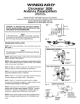
1
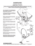
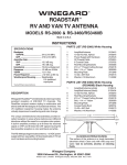
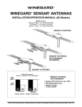
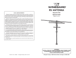
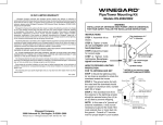
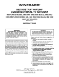
STEP 5. Mount power supply in wall with
screws provided and attach TV set cable to jack
on front. Connect band separator to VHF and
UHF antenna terminals of TV set, if required.
Press switch on front of outlet and check that
light is on.
INSTALLING FC-5910
CONNECTORS ON COAX CABLE
Figure 4
Figure 5
STEP 1: Strip outer cover back 1/2"* from end of cable. Fray
braid back as far as outer cover will allow.
Set 2
STEP 2: Trim braid close to outer cover and remove 1/4"* of
inner insulation being careful not to nick center conductor.
Make sure no foil or braid can touch center conductor.
STEP 3: Slide connector tip between braid and inner insulation
(braid and foil, on foil shield cable) and push connector on cable
as far as it will go. Crimp built-in ferrule with proper crimping
tool. Hex connector requires hex crimping tool. Do Not crush
cable out-of-round. * If installing in very hot weather, increase
these dimensions 1/8".
Antenna
Cable
OPERATION: To receive cable signals from
outdoor receptacle: Press switch to OFF
(CABLE) position. Light on wall plate will go off
showing that power is no longer connected to
the antenna and that both TV sets are receiving
signals from outdoor receptacle.
To receive signals from antenna: Press
switch to ON (ANT) position. Light on wallplate
will come on showing that power is connected
to the antenna and both TV sets are receiving
signals from the antenna.
NOTE: Make sure the antenna is in the
operating position (up) and pointed at the
station desired.
STEP 5. Mount power supply in wall with
screws provided and attach TV set cable to jack
on front. Connect band separator to VHF and
UHF antenna terminals of TV set, if required.
Press switch on front of outlet and check that
light is on.
WINEGARD MOBILE PRODUCTS LIMITED WARRANTY
(2 YEARS PARTS; 1 YEAR LABOR)
Winegard Company warrants this product against defects in
materials or workmanship for a period of two (2) years from the
date of original purchase. During year one (1) of such warranty,
Winegard Company will also pay authorized labor costs to an
authorized Winegard dealer to repair or replace defective
products. No warranty claim will be honored unless at the time
the claim is made, Customer presents proof of purchase to an
authorized Winegard dealer (to locate the nearest authorized
Winegard dealer, contact Winegard Company, 3000 Kirkwood
Street, Burlington, Iowa 52601, Telephone 800-288-8094 or
visit www.winegard.com). Customer must provide proof of
purchase with a dated sales receipt for the Winegard product
to verify the product is under warranty. If the date of purchase
cannot be verified, the warranty period shall be considered to
begin thirty (30) days after the date of manufacture.
If a defect in material or workmanship is discovered, Customer
may take the product to an authorized Winegard dealer for
service. Customer must provide proof of purchase to verify
the product is under warranty. If the product is brought to an
authorized Winegard dealer for service prior to expiration of
year one (1) of the warranty period and a defect in material
or workmanship is verified by Winegard Technical Services,
Winegard Company will cover the Winegard dealer’s labor
charges for warranty service. The Winegard dealer must
contact Winegard Technical Services in advance for preapproval of the service. Approval of the service is at the sole
discretion of Winegard Company.
INSTALLING FC-5910
CONNECTORS ON COAX CABLE
Figure 4
Figure 5
STEP 1: Strip outer cover back 1/2"* from end of cable. Fray
braid back as far as outer cover will allow.
Set 2
STEP 2: Trim braid close to outer cover and remove 1/4"* of
inner insulation being careful not to nick center conductor.
Make sure no foil or braid can touch center conductor.
STEP 3: Slide connector tip between braid and inner insulation
(braid and foil, on foil shield cable) and push connector on cable
as far as it will go. Crimp built-in ferrule with proper crimping
tool. Hex connector requires hex crimping tool. Do Not crush
cable out-of-round. * If installing in very hot weather, increase
these dimensions 1/8".
Antenna
Cable
OPERATION: To receive cable signals from
outdoor receptacle: Press switch to OFF
(CABLE) position. Light on wall plate will go off
showing that power is no longer connected to
the antenna and that both TV sets are receiving
signals from outdoor receptacle.
To receive signals from antenna: Press
switch to ON (ANT) position. Light on wallplate
will come on showing that power is connected
to the antenna and both TV sets are receiving
signals from the antenna.
NOTE: Make sure the antenna is in the
operating position (up) and pointed at the
station desired.
WINEGARD MOBILE PRODUCTS LIMITED WARRANTY
(2 YEARS PARTS; 1 YEAR LABOR)
Winegard Company warrants this product against defects in
materials or workmanship for a period of two (2) years from the
date of original purchase. During year one (1) of such warranty,
Winegard Company will also pay authorized labor costs to an
authorized Winegard dealer to repair or replace defective
products. No warranty claim will be honored unless at the time
the claim is made, Customer presents proof of purchase to an
authorized Winegard dealer (to locate the nearest authorized
Winegard dealer, contact Winegard Company, 3000 Kirkwood
Street, Burlington, Iowa 52601, Telephone 800-288-8094 or
visit www.winegard.com). Customer must provide proof of
purchase with a dated sales receipt for the Winegard product
to verify the product is under warranty. If the date of purchase
cannot be verified, the warranty period shall be considered to
begin thirty (30) days after the date of manufacture.
If a defect in material or workmanship is discovered, Customer
may take the product to an authorized Winegard dealer for
service. Customer must provide proof of purchase to verify
the product is under warranty. If the product is brought to an
authorized Winegard dealer for service prior to expiration of
year one (1) of the warranty period and a defect in material
or workmanship is verified by Winegard Technical Services,
Winegard Company will cover the Winegard dealer’s labor
charges for warranty service. The Winegard dealer must
contact Winegard Technical Services in advance for preapproval of the service. Approval of the service is at the sole
discretion of Winegard Company.
Alternatively, Customer may ship the product prepaid to
Winegard Technical Services (located at 3111 Kirkwood
Street, Burlington, Iowa 52601, Telephone 800-7884417). Customer must return the product along with a brief
description of the problem and provide Winegard Technical
Services with Customer’s name, address, and phone number.
Customer must also provide proof of purchase to verify the
product is under warranty. If the product is returned before the
expiration of the warranty period, Winegard Company will (at
its option) either repair or replace the product.
This Limited Warranty does not apply if the product has been
damaged, deteriorates, malfunctions or fails from: improper
installation, misuse, abuse, neglect, accident, tampering,
modification of the product as originally manufactured by
Winegard in any manner whatsoever, removing or defacing
any serial number, usage not in accordance with product
instructions or acts of nature such as damage caused by
wind, lightning, ice or corrosive environments such as salt
spray and acid rain. This Limited Warranty also does not
apply if the product becomes unable to perform its’ intended
function in any way as a result of the television signal provider
making any changes in technology or service.
RETURN AUTHORIZATION POLICY
A Return Material Authorization (RMA) is required prior to
returning any product to Winegard Company or Winegard
Warranty Services under this warranty policy. Please call our
Technical Services Department at 800-788-4417 or send an
e-mail to [email protected] to obtain the RMA number.
Please furnish the date of purchase when requesting an RMA
number. Enclose the product in a prepaid package and
write the RMA number in large, clear letters on the outside
of the package. To avoid confusion or misunderstanding, a
shipment(s) without an RMA number(s) or an unauthorized
return(s) will be refused and returned to Customer freight
collect.
WINEGARD COMPANY DOES NOT ASSUME ANY
LIABILITIES FOR ANY OTHER WARRANTIES, EXPRESS
OR IMPLIED, MADE BY ANY OTHER PERSON.
ALL OTHER WARRANTIES WHETHER EXPRESS, IMPLIED
OR STATUTORY INCLUDING WARRANTIES OF FITNESS
FOR A PARTICULAR PURPOSE AND MERCHANTABILITY
ARE LIMITED TO THE TWO YEAR PERIOD OF THIS
WARRANTY.
In states that do not allow limitations on implied warranties,
or the exclusion of limitation of incidental or consequential
damages, the above limitations or exclusions do not apply.
Some states do not allow limitations on how long an implied
warranty lasts, or the exclusion of limitation of incidental
or consequential damages, so the above limitations or
exclusions may not apply to you.
This warranty gives Customer specific legal rights.
Customer may also have other rights that may vary from
state to state.
SATELLITE RECEIVER WARRANTY
See manufacturer’s limited warranty policy.
WS-MOBWARREREV 2 Rev.1/10
INSTRUCTIONS
MODELS RV-7012, RV-7032, RV-7042
Made in U.S.A.
RV WALL PLATE/
POWER SUPPLY
This unit is equipped with a polyswitch,
(current limiting device), which will shut down
+12VDC if there is a direct short between
antenna and power supply. Green indicator light
will not light. Once short is eliminated, device will
reset itself in approximately 2 minutes.
DESCRIPTION
Wall plate/power supply to operate Winegard
RV antenna with outdoor receptacle for TV
set and cable input. Wall plate/power supply
provides +12VDC to antenna and +12 volt
receptacle as well as antenna signals to two
TV sets. Cable input from outdoor receptacle
connects to wall plate and may be switched so
either antenna or cable signals may be watched.
See applications.
NOTE: THIS UNIT IS NOT AN AMPLIFIER. USE ONLY
WITH A WINEGARD AMPLIFIED RV ANTENNA.
WINEGARD COMPANY
3000 KIRKWOOD ST., BURLINGTON, IA 52601-2000
Printed in U.S.A. 2451486 Rev.2 1/10
Alternatively, Customer may ship the product prepaid to
Winegard Technical Services (located at 3111 Kirkwood
Street, Burlington, Iowa 52601, Telephone 800-7884417). Customer must return the product along with a brief
description of the problem and provide Winegard Technical
Services with Customer’s name, address, and phone number.
Customer must also provide proof of purchase to verify the
product is under warranty. If the product is returned before the
expiration of the warranty period, Winegard Company will (at
its option) either repair or replace the product.
This Limited Warranty does not apply if the product has been
damaged, deteriorates, malfunctions or fails from: improper
installation, misuse, abuse, neglect, accident, tampering,
modification of the product as originally manufactured by
Winegard in any manner whatsoever, removing or defacing
any serial number, usage not in accordance with product
instructions or acts of nature such as damage caused by
wind, lightning, ice or corrosive environments such as salt
spray and acid rain. This Limited Warranty also does not
apply if the product becomes unable to perform its’ intended
function in any way as a result of the television signal provider
making any changes in technology or service.
RETURN AUTHORIZATION POLICY
A Return Material Authorization (RMA) is required prior to
returning any product to Winegard Company or Winegard
Warranty Services under this warranty policy. Please call our
Technical Services Department at 800-788-4417 or send an
e-mail to [email protected] to obtain the RMA number.
Please furnish the date of purchase when requesting an RMA
number. Enclose the product in a prepaid package and
write the RMA number in large, clear letters on the outside
of the package. To avoid confusion or misunderstanding, a
shipment(s) without an RMA number(s) or an unauthorized
return(s) will be refused and returned to Customer freight
collect.
WINEGARD COMPANY DOES NOT ASSUME ANY
LIABILITIES FOR ANY OTHER WARRANTIES, EXPRESS
OR IMPLIED, MADE BY ANY OTHER PERSON.
ALL OTHER WARRANTIES WHETHER EXPRESS, IMPLIED
OR STATUTORY INCLUDING WARRANTIES OF FITNESS
FOR A PARTICULAR PURPOSE AND MERCHANTABILITY
ARE LIMITED TO THE TWO YEAR PERIOD OF THIS
WARRANTY.
In states that do not allow limitations on implied warranties,
or the exclusion of limitation of incidental or consequential
damages, the above limitations or exclusions do not apply.
Some states do not allow limitations on how long an implied
warranty lasts, or the exclusion of limitation of incidental
or consequential damages, so the above limitations or
exclusions may not apply to you.
This warranty gives Customer specific legal rights.
Customer may also have other rights that may vary from
state to state.
SATELLITE RECEIVER WARRANTY
See manufacturer’s limited warranty policy.
WS-MOBWARREREV 2 Rev.1/10
INSTRUCTIONS
MODELS RV-7012, RV-7032, RV-7042
Made in U.S.A.
RV WALL PLATE/
POWER SUPPLY
This unit is equipped with a polyswitch,
(current limiting device), which will shut down
+12VDC if there is a direct short between
antenna and power supply. Green indicator light
will not light. Once short is eliminated, device will
reset itself in approximately 2 minutes.
DESCRIPTION
Wall plate/power supply to operate Winegard RV
antenna with outdoor receptacle for TV set and
cable input. Wall plate/power supply provides
+12VDC to antenna and +12 volt receptacle
as well as antenna signals to two TV sets.
Cable input from outdoor receptacle connects
to wall plate and may be switched so either
antenna or cable or signals may be watched.
See applications.
NOTE: THIS UNIT IS NOT AN AMPLIFIER. USE ONLY
WITH A WINEGARD AMPLIFIED RV ANTENNA.
WINEGARD COMPANY
3000 KIRKWOOD ST., BURLINGTON, IA 52601-2000
Printed in U.S.A. 2451486 Rev.2 1/10
WARNING: Use of this on/off
power switch with any product
other than Winegard amplified
RV antenna, could result in fire
or other damage.
Antenna
Antenna
Input
Outdoor Receptacle
WA-1010
Cable
Input
Set 2
APPLICATIONS AND
ALTERNATE CONNECTIONS
Antenna
Outdoor Receptacle
WA-1010
Cable Input
TV
Outlet
Antenna
Input
TG-7221
Example 2
Antenna
ON/OFF
Switch
Outdoor Receptacle
WA-1010
Cable
Input
Antenna
Input
Set 2
TV
Outlet
Set 1
WARNING: Do Not Connect High
Current Devices Such as Hair
Dryers to +12 Volt Receptacle
on Wall Plate/Power Supply.
Maximum current ratings of
this receptacle is 7.5 amps at
+12 VDC.
WARNING: Use of this on/off
power switch with any product
other than Winegard amplified
RV antenna, could result in fire
or other damage.
SP-1002
Splitter
ON/OFF
Switch
Set 1
TG-7221
Outdoor Receptacle
WA-1010
Cable
Input
Set 2
Outdoor Receptacle
WA-1010
Cable Input
TV
Outlet
Antenna
Input
TG-7221
Example 2
Antenna
ON/OFF
Switch
Outdoor Receptacle
WA-1010
Cable
Input
Antenna
Input
Set 2
TV
Outlet
Set 1
WARNING: Do Not Connect High
Current Devices Such as Hair
Dryers to +12 Volt Receptacle
on Wall Plate/Power Supply.
Maximum current ratings of
this receptacle is 7.5 amps at
+12 VDC.
SP-1002
Splitter
ON/OFF
Switch
Set 1
+12 VDC
Ground
Figure 2
WARNING
DO NOT connect high
current devices such
as hair dryers to this
receptacle. Maximum
current rating of this
receptacle is 7.5 amps
at 12 VDC.
INSTRUCTIONS
STEP 1. Select location for wall plate and
patio receptacle. Run two coax cables between
locations and install connectors on each end.
Mark cables so "cable input" and "TV output"
may be identified. Antenna downlead and
+12 VDC will also be needed at inside wall
plate/power supply location.
STEP 2. The wall plate/power supply assembly
may be flush mounted in most standard electrical
boxes. To flush mount cut a hole in wall to fit the
box. Run 2 #12 wires between wall plate/power
supply and +12VDC source and route downlead
cable to this location. Install cable between set 2
outlet and power supply location at this time.
Crimp Here
#12 Wire
1/4"
Connector
Insulation
Connector
Ferrule
Remove 1/4" of
insulation from
#12 wire.
Figure 1
+12 VDC
Ground
STEP 3. Make +12 volt connection to wall
plate/power supply Figure 2. Install terminals
on wires from +12VDC source as shown in
Figure 1. Crimp terminals with Craftsman type
4 crimping tool or equivalent. Push wires onto
tabs on terminal board as shown in Figure 2. If
in doubt as to the polarity of the wires, connect
them temporarily to tabs on circuit board and
press switch on front of outlet. If light comes
on, polarity is correct. See Figure 3.
Figure 2
STEP 4. Install connectors on downlead
and set 2 cable as shown in Figure 5. Attach
downlead cable to jack on wall plate/power
supply marked antenna as shown in Figure
4. Attach cable going to set 2 outlet to jack
on power supply marked SET 2. Attach cable
coming from cable input to jack on power supply
marked CABLE.
WARNING
DO NOT connect high
current devices such
as hair dryers to this
receptacle. Maximum
current rating of this
receptacle is 7.5 amps
at 12 VDC.
INSTRUCTIONS
STEP 1. Select location for wall plate and
patio receptacle. Run two coax cables between
locations and install connectors on each end.
Mark cables so "cable input" and "TV output"
may be identified. Antenna downlead and
+12 VDC will also be needed at inside wall
plate/power supply location.
STEP 2. The wall plate/power supply assembly
may be flush mounted in most standard electrical
boxes. To flush mount cut a hole in wall to fit the
box. Run 2 #12 wires between wall plate/power
supply and +12VDC source and route downlead
cable to this location. Install cable between set 2
outlet and power supply location at this time.
Crimp Here
1/4"
Connector
Insulation
Figure 1
Connector
Ferrule
#12 Wire
Remove 1/4" of
insulation from
#12 wire.
+12 VDC
Ground
WHEN CONNECTING CABLE OR WIRES
BE SURE SWITCH IS IN OFF POSITION.
Set 1
Set 2
Cable Input
Example 1
ON/OFF
Switch
Figure 1
Figure 3
APPLICATIONS AND
ALTERNATE CONNECTIONS
Antenna
Remove 1/4" of
insulation from
#12 wire.
STEP 4. Install connectors on downlead
and set 2 cable as shown in Figure 5. Attach
downlead cable to jack on wall plate/power
supply marked antenna as shown in Figure
4. Attach cable going to set 2 outlet to jack
on power supply marked SET 2. Attach cable
coming from cable input to jack on power supply
marked CABLE.
Example 3
Antenna
Antenna
Input
Connector
Insulation
#12 Wire
WHEN CONNECTING CABLE OR WIRES
BE SURE SWITCH IS IN OFF POSITION.
Set 1
Set 2
Cable Input
Example 1
ON/OFF
Switch
1/4"
Connector
Ferrule
Figure 3
APPLICATIONS AND
ALTERNATE CONNECTIONS
Antenna
STEP 3. Make +12 volt connection to wall
plate/power supply Figure 2. Install terminals
on wires from +12VDC source as shown in
Figure 1. Crimp terminals with Craftsman type
4 crimping tool or equivalent. Push wires onto
tabs on terminal board as shown in Figure 2. If
in doubt as to the polarity of the wires, connect
them temporarily to tabs on circuit board and
press switch on front of outlet. If light comes
on, polarity is correct. See Figure 3.
Example 3
Antenna
Antenna
Input
STEP 2. The wall plate/power supply assembly
may be flush mounted in most standard electrical
boxes. To flush mount cut a hole in wall to fit the
box. Run 2 #12 wires between wall plate/power
supply and +12VDC source and route downlead
cable to this location. Install cable between set 2
outlet and power supply location at this time.
Crimp Here
WHEN CONNECTING CABLE OR WIRES
BE SURE SWITCH IS IN OFF POSITION.
Set 1
Set 2
Cable Input
Example 1
ON/OFF
Switch
INSTRUCTIONS
STEP 1. Select location for wall plate and
patio receptacle. Run two coax cables between
locations and install connectors on each end.
Mark cables so "cable input" and "TV output"
may be identified. Antenna downlead and
+12 VDC will also be needed at inside wall
plate/power supply location.
Example 3
STEP 3. Make +12 volt connection to wall
plate/power supply Figure 2. Install terminals
on wires from +12VDC source as shown in
Figure 1. Crimp terminals with Craftsman type
4 crimping tool or equivalent. Push wires onto
tabs on terminal board as shown in Figure 2. If
in doubt as to the polarity of the wires, connect
them temporarily to tabs on circuit board and
press switch on front of outlet. If light comes
on, polarity is correct. See Figure 3.
Figure 2
STEP 4. Install connectors on downlead and
set 2 cable as shown in Figure 5. Attach downlead
cable to jack on wall plate/power supply marked
antenna as shown in Figure 4. Attach cable going
to set 2 outlet to jack on power supply marked
SET 2. Attach cable coming from cable input to
jack on power supply marked CABLE.
WARNING
DO NOT connect high
current devices such
as hair dryers to this
receptacle. Maximum
current rating of this
receptacle is 7.5 amps
at 12 VDC.
TG-7221
Figure 3