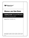
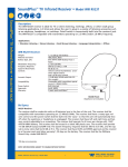
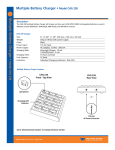
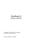
1
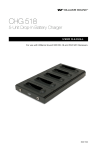
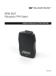
Interpreter’s Control Center, Model IC-1
Description:
This self-contained audio control center lets interpreters listen to the program directly from the floor or another
interpreter while simultaneously interpreting into a microphone. Used as a stand-alone unit, the IC–1 is capable
of handling dual language applications. Used in tandem, multiple IC-1s may be combined to economically
handle up to four languages.
Interpreter Control Center, Model IC-1:
Dimensions, Weight:
Color:
Power:
INPUTS
Floor In, Relay In:
1/4" Microphone Inputs:
3.5 mm Microphone Inputs:
OUTPUTS
Key Out, Norm Out:
Phones:
CONTROLS
Volume:
Mic Switch:
Mute Switch:
Function Switch:
OFF Mode:
NORM Mode:
RELAY Mode:
KEY Mode:
Feedthru Jumpers:
J1
J2
Recommended Microphone
MIC 079
ON Indicator Light:
Warranty:
7" (17.7 cm) W x 5.625" (14.3 cm) D x 3.125" (9.3 cm) H, 1.82 lbs (.83 kg)
Beige epoxy paint with black legends, blue bottom and side panels
External power supply, 12 VAC, 50 or 60 Hz, 10 VA, (TFP 008 Power Supply)
(A 240 VAC Power Supply is also available, TFP 008 HV)
3-Pin XLR female jack, balanced or unbalanced line-level, max. 3.8 Vrms,
Gain 6 dB, 43 kΩ input impedance
Left and right, 1/4" TRS phone jack, balanced or unbalanced mic-level,
max. 70 mVrms, gain 46 dB, supplies simplex DC power for electret mics,
1.75 kΩ input impedance
Left and right, 3.5 mm TRS phone jack, unbalanced (T,S) for condenser mics,
max. 70 mVrms, gain 46 dB, supplies DC power on tip, 1.75 kΩ input impedance
3-Pin XLR male jack, balanced or unbalanced line-level, 7.7 max. Vrms,
56 Ω source impedance
3.5 mm TRS phone jack, mono or stereo headphone, 8-32 Ω,
63.7 mW at 8 Ω load max
Left and right, rotary, controls headphones volume
3–way toggle. Selects left mic, right mic, or both.
Push button. Mutes left and right mics when depressed.
4-way push button. Selects OFF, NORM, RELAY, or KEY modes.
Floor input (FLOOR IN) is fed to the interpreter’s headphones to allow monitoring of the meeting.
Interpreter’s microphones are muted.
Floor input (FLOOR IN) is fed to the interpreter’s headphones. The selected interpreter’s microphone
is fed to the normal output (NORM OUT).
Interpreter monitors the relay input (RELAY IN) while the selected microphone feeds the normal output (NORM OUT)
Used to feed a second language audience. The interpreters monitor the floor input (FLOOR IN)
while mics feed the key output (KEY OUT).
Located on bottom of cabinet. Used to select floor signal feedthru options.
Feeds the floor signal to the normal output (NORM OUT)
Feeds the floor signal to the key output (RELAY OUT)
Dual headphone, condenser mic, 3.5 mm plug (MIC 079), Audio Indicator Light: Yellow LED,
flashes when audio signal is present
Green LED, glows when power is applied to the transmitter. There is no on/off switch.
The T17 is designed to be left on continuously.
3 years, parts and labor*
*90 day warranty on accessories
NOTE: SPECIFICATIONS SUBJECT TO CHANGE WITHOUT NOTICE!
©2005, Williams Sound Corp. CAT 063C
Williams
Sound ®
Helping People Hear
1
Interpreter’s Control Center, Model IC-1
Microphone
IC-1 Interpreter's Control Center
Left
Microphone
Mic Phones
Right
L
R
Phones Mic
L+R
Off
Norm Relay Key
IC–1 Front Panel
Left Volume
2
3
Right Volume
1
5
0
6
3
2
4
4
Interpreter's Control Center
1
Model IC-1
5
Microphone
Mute
6
0
Floor In
Norm Out
Key Out
Relay In
Power
12 VAC
Williams Sound ®
Made in U.S.A.
Williams Sound Corp.
IC–1 Top Panel
IC–1 Rear Panel
TX9 Emitter
Baseband
Input
Podium
(Floor)
Mixer
Baseband
Output
MOD 232 Modulator
Two Channel Infrared System Modulator
Microprocessor Controlled
Frequency Synthesized
Power
4 5 6
3
2
1
0
+9
+6
+3
0
-3
-6
-9
-12
-15
-18
7
8
9
10
Level
3.3
MOD 232 Modulator
Williams Sound
+9
+6
+3
0
-3
-6
-9
-12
-15
-18
3.8
Compress
2.8
2.3
Frequency
(MHz)
4 5 6
3
2
1
0
7
8
9
10
Level
Inputs Mixed
3.8
3.3
Compress
2.8
2.3
Frequency
(MHz)
Phones
Coaxial
Cable
Williams
Two Channel Infrared System Modulator
Microprocessor Controlled
Frequency Synthesized
IR
Power
CH A
4 5 6
3
2
1
Stereo
0
CH B
10
Level
Channel B
Channel A
+9
+6
+3
0
-3
-6
-9
-12
-15
-18
7
8
9
Williams Sound
+9
+6
+3
0
-3
-6
-9
-12
-15
-18
3.8
3.3
Compress
2.8
2.3
Frequency
(MHz)
4 5 6
3
2
1
0
7
8
9
10
Level
3.3
Compress
2.8
2.3
Sound
IR
4 channel
Inputs Mixed
3.8
Frequency
(MHz)
Phones
Stereo
IR
CH A
CH B
Channel B
Channel A
Williams
Sound
IR
4 channel
Input CHA
Distribution
Amp
Input CHA
Input CHB
Input CHB
Norm Out
RX12-4 Receiver
IC-1 Interpreter's Control Center
Floor In
Left Volume
Right Volume
Microphone
Mute
Norm Out
Williams Sound
Mic
IC-1
IC-1 Interpreter's Control Center
Floor In
Right Volume
Left Volume
Microphone
Mute
Norm Out
Williams Sound
IC-1 Interpreter's Control Center
Mic
IC-1
Floor In
Left Volume
Right Volume
Microphone
Mute
Norm Out
Williams Sound
Mic
IC-1
IC-1 Interpreter's Control Center
Floor In
Right Volume
Left Volume
Microphone
Mute
Williams Sound
Mic
Interpreter
#1
Interpreter
#2
Interpreter
#3
IC-1
Interpreter
#4
NOTE: SPECIFICATIONS SUBJECT TO CHANGE WITHOUT NOTICE!
©2005, Williams Sound Corp. CAT 063C
Williams
Sound ®
Helping People Hear
2
Interpreter’s Control Center, Model IC-1
Bid Specs
The unit shall be 7 inches wide, 5 5 ⁄ 8 inches deep and 3 1⁄ 8 inches tall. The unit shall weigh 1.82 lbs. The module
shall be painted beige with black legends indicating controls, inputs and outputs. The bottom and side panels shall
be painted blue. The power supply shall be external, 12 VAC, 50 or 60 Hz, 10 VA. An optional 240 VAC Power Supply
shall also be available. Inputs shall be configured as follows: The “Floor In” and “Key In” inputs shall be 3-Pin, XLR
female jacks, allowing balanced or unbalanced line-level inputs. Maximum input levels shall be 3.8 Vrms. Gain
shall be 6 dB with 43 kΩ input impedance. There shall be two microphone inputs, both 1 ⁄ 4" TRS phone jacks, balanced or unbalanced. These inputs shall be mic-level, allowing a maximum 70 mVrms and 46 dB gain. The two
microphone inputs shall supply simplex DC power for electret mics with 1.75 kΩ input impedance. There shall be
two independent 3.5 mm TRS microphone inputs (unbalanced [T,S] for condenser mics), allowing a maximum 70
mVrms. Gain shall be 46 dB. The two 3.5 mm inputs shall supply DC power on tip, 1.75 kΩ input impedance.
Outputs
The “Key Out” and “Norm Out” outputs shall be 3-Pin XLR male jacks, balanced or unbalanced line-level.
Maximum output shall be 7.7 Vrms. Source impedance shall be 56 Ω. There shall be two independent 3.5 mm TRS
headphone output jacks (left right). The headphone outputs shall allow the use of either mono or stereo headphones, 8-32 Ω. Maximum power shall be 63 mW at 8 Ω.
Controls
The unit shall have two, independent rotary-type volume controls, controlling headphone volume. The
“Microphone” switch shall be a 3–way toggle type, selecting left mic, right mic or both. The mute switch shall be
a push button-type, muting left and right mics when depressed. The function switch shall be a 4-way push buttontype, selecting OFF, NORM, RELAY or KEY modes.
Controls
Feedthru jumpers used to select floor signal feedthru options shall be located on bottom of cabinet.The unit shall
be Williams Sound Corp. Interpreter Control Center, model IC-1.
NOTE: SPECIFICATIONS SUBJECT TO CHANGE WITHOUT NOTICE!
©2005, Williams Sound Corp. CAT 063C
Williams
Sound ®
Helping People Hear
3
Interpreter’s Control Center, Model IC-1
Contact:
United States and Mexico
Williams Sound Corp.
10321 W. 70th Street
Eden Prairie, MN 55344-3446
Ph: 800-328-6190 / 952-943-2252 / FAX: 952-943-2174
Web: www.williamssound.com
Email: [email protected]
Canada
Thorvin Electronics
2861 Sherwood Heights Dr. Units 36-37
Oakville, ON L6J-7K1 Canada
Ph: 800-323-6634 / 905-829-3040 / FAX: 905-829-4196
Web: www.thorvinelectronics.com
South America
DPTech
SIA Trecho 3/4 Lote 335 2°. Andar
71200-030 Brasília, DF
BRAZIL
Ph: (5561) 361-1384
Fax: (5561) 361-0948
Web: www.dptech.com.br
Email: [email protected]
Europe and Asia
International Sales Department
Williams Sound Corp.
10321 W. 70th Street
Eden Prairie, MN 55344 USA
Phone: +1 952 943 2252
Fax: +1 952 943 2174
Email: [email protected]
Web: www.williamssound.com
©2005, Williams Sound Corp. CAT 063C
Williams
Sound ®
Helping People Hear
4