1
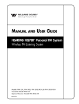
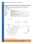
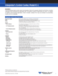
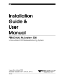
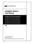
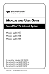
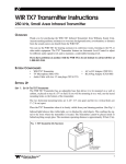
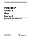
SoundPlus® Infrared System • Model WIR TX900
D
SoundPlus® Infrared System • Model WIR TX900
Description:
The WIR TX900 is a high performance, cost-effective infrared system designed for simultaneous language interpretation of up to four languages. Operating on 2.3-3.8 MHz, the WIR TX900 is less susceptible to traditional radio and lighting interference. When using the optional RX22-4 four-channel receiver, the WIR TX900 will operate up to 28,000 ft2 in single channel mode, ideal for auditoriums, theaters or other large venues.
Applications:
• Simultaneous Interpretation • Audio Description • Conferences • Multi-Media Rooms • Boardrooms •
Courtrooms • Schools • Universities • Cinema • Churches
MOD 232 Modulator
Size, Weight:
Color:
Rack Mount:
8.5" W x 8.2" D x 1.7" H (21.5 cm x 20.8 cm x 4.4 cm), 3.1 lbs (1.5 kg)
Black epoxy paint with white legends
1/2 rack space wide, 1 rack space high, one or two modulators may be mounted in a
single IEC rack space with RPK 005 (single) or RPK 006 (double) Rack Mount Kits
Wall Transformer, 24 VAC, 50-60 Hz, 15 VA
North America:
TFP 016, UL/CSA
Europe:
TFP 027-01, 2-pin Schuko plug, CE
UK:
TFP 027-02, 3-pin UK plug, CE
FM Wideband, +50kHz deviation, 50uS pre-emphasis
Channel A: Selectable, 2.3/2.8/3.3/3.8 MHz,
Channel B: Selectable, 2.3/2.8/3.3/3.8 MHz
More than 60 dB
30 to 16,000 Hz, +1 dB, -3 dB, electrical response
Less than 2%, electrical response
Compression (slope) adjustable from 1:1 to 4:1
Switchable compression gain: Moderate: 16 dB. Max: 33 dB
15 minute timer shuts off carrier when no audio is present (can be disabled)
Two-position push button, ON/OFF
Power Supply:
Modulation:
Carrier Frequency:
Signal-to-Noise Ratio:
Frequency Response:
Total Harmonic Distortion:
Audio Processing:
Auto Carrier Shut-Off:
Power Switch:
Fig. 1: MOD 232 Front Panel
Williams Sound
Two Channel Infrared System Modulator
Microprocessor Controlled
Frequency Synthesized
Power
4 5 6
3
2
1
0
7
8
9
10
Level
+9
+6
+3
0
-3
-6
-9
-12
-15
-18
3.8
3.3
2.8
2.3
Frequency
(MHz)
Compress
4 5 6
3
2
1
0
7
8
9
10
Level
Channel A
Power Indicator:
Audio Level Controls:
Audio Indicators:
Carrier LEDs:
Compress Control:
Input Mix LED:
Stereo LED:
Phones Switch:
Inputs Mixed
3.8
3.3
2.8
2.3
Frequency
(MHz)
Compress
Phones
Stereo
IR
CH A
CH B
Channel B
Green LED
CHA and CHB Input Level, rotary knobs
CHA and CHB Audio Level, 10-segment LED’s
4 green LED carrier “on” indicators per channel (indicates frequency, malfunctions)
1:1 to 4:1
Indicates inputs A and B audio are mixed and transmitted by CHA, CHB off
Indicates stereo mode
Selects CH1 or CH2 for phones when not in stereo mode
NOTE: SPECIFICATIONS SUBJECT TO CHANGE WITHOUT NOTICE!
©2006, Williams Sound Corp. CAT 089F
+9
+6
+3
0
-3
-6
-9
-12
-15
-18
1
SoundPlus® Infrared System • Model WIR TX900
D
SoundPlus® Infrared System • Model WIR TX900
Fig. 2: MOD 232 Rear Panel
Input CH A
Input CH B
CH A
12345678
Phones Output:
Infrared Test LED:
Power Input:
Audio Input Jack:
Mic Level:
Line Level:
Audio Line Output Jacks:
Configuration Switches:
Baseband Input Jack:
Baseband Output Jack:
Approvals:
Operating Requirements:
Warranty:
Baseband
Output
Output
Power In
12345678
24 VAC, 15 VA, 50-60 Hz
Configuration
Switches
Made in USA
Williams Sound
Input
CH A
CH B
MOD 232 Infrared System Modulator
Audio Line
Output
Plug
CH B
100 Ohms
50 Ohms
24V
1/4" TRS headphone jack. Accepts stereo, mono, and any impedance phones.
IR LED for receiver testing, monitoring, and audio signal testing
3-Pin Molex, 24 VAC, 50-60 Hz, 15 VA
CHA and CHB combination XLR/TRS jack
Balanced, Lo-Z, 100 µV min. to 90 mV max., 1mV nominal, 3 kΩ input impedance, supplies switchable simplex power per DIN 45596 for condenser mics
Balanced or unbalanced, 21 mV min. to 10V max., 212 mV nominal, 100 kΩ
RCA Jack, CHA and CHB, 500 mV, unbalanced, 100 Ω source impedance, load impedance must be greater than 1 kΩ
CHA and CHB 8-position DIP switch, selects Mic/Line input, compressor gain, simplex
power, discrete or mixed inputs, carrier frequency, channel disable, auto shut-off timer
BNC, allows mixing with additional MOD 232 Modulator (4CH operation), 100 mV, 50
Ω input impedance, use with MOD 232, BNC, RG-58 Cable
Two BNC jacks carry baseband signal, 100 mV/channel, 50Ω source impedance, for use
with WIR TX9 or MOD 232 only
CE, FCC, RoHS, WEEE
0-50º C ambient temperature, non-condensing, non-corrosive atmosphere
5 years on modulator, 90 days on accessories
WIR TX9 Emitter:
Dimensions, Weight:
Color:
Power Supply:
Power Cable:
Indicators:
Carrier Frequency:
Emitter IR Power:
Coverage Area:
Baseband Input:
Baseband Output:
Baseband Cable:
Operating Requirements:
Mounting Kits:
Warranty:
Approvals:
Compatible Receivers:
11.25" W x 6.25" H x 2.125" D (28.6 cm x 15.9 cm x 5.4 cm), 1.9 lbs (0.9 kg)
Black with white legends, red acrylic lens
Wall Transformer, 24 VAC, 50-60 Hz, 35 VA, 3-pin MOLEX Connector
North America:
TFP 010, UL/CSA
Europe:
TFP 027-01, 2-pin Schuko plug, CE
UK:
TFP 027-02, 3-pin UK plug, CE
Note: Each WIR TX9 requires its own power supply
NEC Class 2 wiring, two-conductor, 18 ga., 200’ (61m) max. length
Green LED power indicator, red LED baseband indicator
50 kHz to 8 MHz
3.5 watts
28,000 ft2 (2,600 m2) in single-channel mode when using the RX22-4 Receiver
11,000 ft2 (1,000 m2) in four-channel mode when using the RX22-4 Receiver
3,500 ft2 (325 m2) in single-channel mode when using the RX14-2 Receiver
3,063 ft2 (285 m2) in single-channel mode when using the RX16 Receiver
(See coverage area diagrams)
BNC, 100 mV per carrier, 50Ω, for use with WIR TX9 or MOD 232 only
BNC, 50 Ω, for use with TX9 only
RG 58 Coax, BNC connectors, maximum 1000’ (300m) length
0-50º C ambient temperature, non-condensing, non-corrosive atmosphere
Wall or Ceiling Mount: BKT 024 Omnidirectional mount, Mic Stand Kit: SS-11 or SS-6
5 years on emitter, 90 days on accessories
CE, FCC, RoHS, WEEE
WIR RX22-4 Four-Channel Receiver, RX14-2 Two-Channel Receiver,
RX16 Two-Channel Receiver
NOTE: SPECIFICATIONS SUBJECT TO CHANGE WITHOUT NOTICE!
©2006, Williams Sound Corp. CAT 089F
2
SoundPlus® Infrared System • Model WIR TX900
D
SoundPlus® Infrared System • Model WIR TX900
Fig. 3: WIR TX9 Rear Panel
Multi-Channel Infrared Transmitter
RoHS
CAUTION
RISK OF ELECTRIC SHOCK
DO NOT OPEN
Class 1
LED Product
www.williamssound.com
WARNING: TO REDUCE THE RISK OF FIRE OR
ELECTRIC SHOCK DO NOT EXPOSE THIS
EQUIPMENT TO RAIN OR MOISTURE.
Mounting
Bracket
Note: It is normal for this unit to feel warm while it is in operation.
Power Supply Wiring:
Use NEC, Class 2 Wiring, 18 ga. minimum,
200 ft. (70m) maximum length (18 ga.)
Baseband Signal Wiring:
Baseband Signal Wiring:
Use 50 Ohm Coaxial Cable (RG58)
Use RG58 Coax,1000 ft. (350m) max. length
Williams Sound Corp., Minneapolis, Minnesota, USA
Patent Pending
Made in U.S.A.
Baseband
(Modulation)
NC
24 VAC
Power In:
24VAC
50-60Hz
35VA
~
Out
Plug
Out
In
50 Ohms
Power On
Baseband On
Fig. 4: Receiver Coverage Area with TX9 Emitter in Single Channel Mode
Feet 90
Receiver Coverage Area with TX9
Transmitter in Single Channel Mode
80
70
60
RX22-4 Receiver
50
RX14-2 Receiver
40
RX16 Receiver
30
20
10
RX16
0
RX14-2
RX22-4
-10
-20
-30
-40
-50
-60
-70
-80
-90
Feet
0
10 20 30 40 50 60 70 80 90 100 110 120 130 140 150 160
The coverage area for the TX9 will vary depending on the receiver being used. The diagram above
demonstrates the receiver coverage when operating a single TX9 emitter in single channel mode.
Patterns are direct radiation patterns.
Note: Reflections of the infrared light from walls, ceilings and floors may change these patterns.
NOTE: SPECIFICATIONS SUBJECT TO CHANGE WITHOUT NOTICE!
©2006, Williams Sound Corp. CAT 089F
3
SoundPlus® Infrared System • Model WIR TX900
D
SoundPlus® Infrared System • Model WIR TX900
Fig. 5: 3-Dimension Foot Pattern
The TX9 floods the listening audience with a
cone shape light pattern as shown here.
The path of the cone shape light leaves a
pattern on the ground, or "foot print, " and
indicates where the strongest receiver
reception will occur.
The actual coverage area will vary depending
on the sensitivity of the receiver being used.
Refer to Figures 4 and 7 to determine how
many emitters are required for 100% coverage
of the listening area.
To determine the best location for the emitter, it helps to think of the IR emitter as an invisible floodlight. You’ll want to aim it so the listeners are “flooded” with the infrared light. The emitter should also
be positioned high enough so it won’t be blocked by people and other physical obstructions. See Figure
6 below. Mount the emitter at least 2 ft. (.61 m) above the audience. Position the emitter to face in a
slightly downward angle, 20°, that will increase the “throw” of the infrared beam.
Fig. 6: Vertical Beam Spread
Minimum Receiver Range When Operating with a TX9 Emitter in Single Channel Mode
RX22-4 Receiver:
150' (45 m)
RX14-2: 80' (24 m)
RX16: 70' (21 m)
(Range)
TX9
Center Of
m
Emitter Bea
30'
SCREEN
6'
STAGE
NOTE: SPECIFICATIONS SUBJECT TO CHANGE WITHOUT NOTICE!
©2006, Williams Sound Corp. CAT 089F
4
SoundPlus® Infrared System • Model WIR TX900
D
Fig. 7: Horizontal and Vertical Radiation Polar Plots
HORIZONTAL RADIATION POLAR PATTERNS
DISTANCE FROM EMITTER TO 1 nW/sq cm CONTOUR
54
180
48
160
42
140
36
120
30
– 90
– 80
– 70
– 60
– 50
– 40
– 30
100
24
80
18
60
12
40
6
20
METERS
200
FEET
60
VERTICAL RADIATION POLAR PATTERNS
DISTANCE FROM EMITTER TO 1 nW/sq cm CONTOUR
60
200
54
180
48
160
42
140
36
120
30
FEET
– 90
METERS
SoundPlus® Infrared System • Model WIR TX900
Maximum Range When Using the RX22-4 Infrared Receiver
– 80
– 70
– 60
– 50
– 40
– 30
100
24
80
18
60
12
40
6
20
– 20
– 20
– 10
– 10
0
0
10
10
20
20
30
30
40
40
50
50
60
60
70
90
70
80
90
80
1 Channel, 1 nW/sq cm
(Approx. 28000 sq ft, 2600 sq m)
1 Channel, 1 nW/sq cm
2 Channel, 1 nW/sq cm per channel
(Approx. 18000 sq ft, 1700 sq m)
2 Channels, 1 nW/sq cm per channel
4 Channel, 1 nW/sq cm per channel
(Approx. 11000 sq ft, 1000 sq m)
4 Channels, 1 nW/sq cm per channel
Reflections of the infrared light from walls, ceilings, and floors may change these patterns.
Important: Remember to point the emitter towards the listening audience!
If you’re not getting sufficient coverage with a single, properly installed TX9 Emitter, you may need
to add additional WIR TX9 Emitters to achieve full coverage of your listening area. Figures 8a and
8b illustrate how multiple emitters can be used for large room installations.
NOTE: SPECIFICATIONS SUBJECT TO CHANGE WITHOUT NOTICE!
©2006, Williams Sound Corp. CAT 089F
5
SoundPlus® Infrared System • Model WIR TX900
D
SoundPlus® Infrared System • Model WIR TX900
Multiple Emitters Installed to Maximize Coverage
Fig. 8a: Overlapping Illumination Patterns to Cover Larger Listening Areas
TX9
TX9
TX9
TX9
Fig. 8a above is a typical example of how multiple emitters are used to cover larger listening areas.
Generally it is desirable for the illumination patterns to overlap. Note: The coverage area will vary depending on the infrared receiver being used; refer to Figures 4 and 7 to determine how many emitters are
required to achieve full coverage of a listening area.
Fig. 8b: Overlapping Illumination Patterns to Cover Larger Listening Areas
Coverage Area
with Single Emitter
TX9
Coverage Area
with Second Emitter
Added to Same
Emission Point
(50% increase)
TX9
When two emitters are used at the same emission point in single channel mode, the overall coverage area increses 50%. When using an RX22-4 receiver, as a result, the coverage area will increase to an estimated 42,000 ft2
(3,902 m2); the RX14-2 will increase to 5,250 ft2 (488 m2); the RX16 will increase to 4,590 ft2 (426 m2 ).
NOTE: SPECIFICATIONS SUBJECT TO CHANGE WITHOUT NOTICE!
©2006, Williams Sound Corp. CAT 089F
6
SoundPlus® Infrared System • Model WIR TX900
D
SoundPlus® Infrared System • Model WIR TX900
WIR RX22-4 Receiver
Receiver Style:
Size:
Weight:
Color and Material:
Lanyard:
Operating Temperature:
Battery Type:
Battery Life:
Battery Drain:
Charging Contacts:
Carrier Frequency:
De-Emphasis:
FM Deviation:
Signal-to-Noise Ratio:
Squelch:
Frequency Response:
Total Harmonic Distortion:
Controls:
Indicators:
Audio Output Jacks:
Audio Output Power:
Acoustic Output:
Sensitivity:
Approvals:
Warranty:
Compatible Headphones/Earphones:
Compatible Headphones/Earphones:
Body-Pack, dual-lens detector, lanyard
4.5" L x 2.85" W x 1.2" H (114.3 mm x 72.4 mm x 30.4 mm)
4.6 oz (130 g) with batteries
Black
3 ft (.91 m), allows receiver to be worn around the neck
-10° C to +50° C
2 x AA, alkaline (BAT 001) or NiMH (BAT 026)
Alkaline: 60 hours, NiMH: 30 hours/charge
25 mA, nominal
For use only with CHG 3512
Channel 1: 2.3 MHz, Channel 2: 2.8 MHz
Channel 3: 3.3 MHz, Channel 4: 3.8 MHz
50 uS
±50 kHz
60dB min.
Receiver squelches (mutes) at 40 dB S/N ratio
25 Hz to 16 KHz, +1 dB, -3 dB, electrical response
Less than 1%, electrical response
ON/OFF/VOLUME: combination thumbwheel knob
Channel Selector: four-position rotary switch
Red LED “ON” indicator, flashes to indicate Low battery
3.5 mm stereo mini phone jack
Accepts 3.5 mm mono or stereo phone plug
15 mW max at 32 Ω
110 dB SSPL90 w/ EAR 013
Better than 1 nW/cm2 for 40 dB signal-to-noise ratio
CE, FCC, RoHS, WEEE
5 years on receiver, 90 days on accessories
Mono or stereo, 8-32 ohms, 3.5 mm mini phone plug, HED
021, HED 026, EAR 013, EAR 014, EAR 022, NKL 001
Mono or stereo, 8-32 Ω, 3.5 mm mini phone plug,
HED 021, EAR 013, EAR 014, EAR 022
Fig. 9: WIR RX22-4
Receiver
Channel
Selector Knob
Earphone
Jack
OFF
"On"
Indicator LED
On/Off
Volume Switch
RX22-4 Top
RX22-4 Front
NOTE: SPECIFICATIONS SUBJECT TO CHANGE WITHOUT NOTICE!
©2006, Williams Sound Corp. CAT 089F
7
SoundPlus® Infrared System • Model WIR TX900
D
SoundPlus® Infrared System • Model WIR TX900
Four-Channel System Diagram
Fig. 10: Four-Channel System
WIR TX9 Emitter (rear)
WIR TX9 Emitter (rear)
Multi-Channel Infrared Transmitter
Multi-Channel Infrared Transmitter
RoHS
RoHS
CAUTION
CAUTION
RISK OF ELECTRIC SHOCK
DO NOT OPEN
Class 1
LED Product
RISK OF ELECTRIC SHOCK
DO NOT OPEN
www.williamssound.com
Class 1
LED Product
WARNING: TO REDUCE THE RISK OF FIRE OR
ELECTRIC SHOCK DO NOT EXPOSE THIS
EQUIPMENT TO RAIN OR MOISTURE.
Mounting
Bracket
Note: It is normal for this unit to feel warm while it is in operation.
Power Supply Wiring:
Mounting
Bracket
Power Supply Wiring:
Use NEC, Class 2 Wiring, 18 ga. minimum,
200 ft. (70m) maximum length (18 ga.)
Use NEC, Class 2 Wiring, 18 ga. minimum,
200 ft. (70m) maximum length (18 ga.)
Baseband Signal Wiring:
Baseband Signal Wiring:
Baseband Signal Wiring:
Baseband Signal Wiring:
Use 50 Ohm Coaxial Cable (RG58)
Use RG58 Coax,1000 ft. (350m) max. length
Williams Sound Corp., Minneapolis, Minnesota, USA
Patent Pending
www.williamssound.com
WARNING: TO REDUCE THE RISK OF FIRE OR
ELECTRIC SHOCK DO NOT EXPOSE THIS
EQUIPMENT TO RAIN OR MOISTURE.
Note: It is normal for this unit to feel warm while it is in operation.
Use 50 Ohm Coaxial Cable (RG58)
Use RG58 Coax,1000 ft. (350m) max. length
Williams Sound Corp., Minneapolis, Minnesota, USA
Patent Pending
Made in U.S.A.
Made in U.S.A.
Baseband
(Modulation)
NC
24 VAC
Power In:
24VAC
50-60Hz
35VA
~
Out
Out
Baseband
(Modulation)
NC
In
Plug
Power On
~
Out
CH A
12345678
MOD 232 Modulator (Rear)
MOD 232 Infrared System Modulator
Audio Line
Output
Input CH A
Williams Sound
Input
Baseband
Output
CH A
50 Ohms
Williams Sound
Input
Baseband
Output
Output
Power In
24 VAC, 15 VA, 50-60 Hz
Plug
CH B
100 Ohms
Made in USA
24V
MOD 232 Infrared System Modulator
Audio Line
Output
12345678
Configuration
Switches
Plug
CH B
100 Ohms
12345678
CH A
CH B
24 VAC, 15 VA, 50-60 Hz
Made in USA
Input CH B
Output
Power In
12345678
Configuration
Switches
Baseband On
Baseband Signal
CH A
CH B
In
50 Ohms
Power On
MOD 232 Modulator (Rear)
Input CH B
Out
Plug
Baseband On
To Additional
Emitters (if necessary)
Input CH A
24 VAC
Power In:
24VAC
50-60Hz
35VA
50 Ohms
50 Ohms
24V
Baseband Signal
CHA
Audio In
CHB
Audio In
WCA 068
CHA
Audio In
SOUND SYSTEM
CHB
Audio In
SOUND SYSTEM
RX22-4 Receiver
(wireless)
NOTE: SPECIFICATIONS SUBJECT TO CHANGE WITHOUT NOTICE!
©2006, Williams Sound Corp. CAT 089F
8
SoundPlus® Infrared System • Model WIR TX900
D
SoundPlus® Infrared System • Model WIR TX900
Bid Specs:
Modulator, Model MOD 232
The infrared system shall consist of separate modulator and emitter units, with portable receivers. The modulator unit shall
be a half-rack style, metal enclosure. A rack panel shall be available to mount one or two modulator units within a single EIA
rack space. An adjustable floor stand and mounting bracket shall be available to mount the modulator and emitter together
for portable operation.
The modulator shall provide two channels of selectable FM carrier signals; 2.3/2.8/3.3/3.8 MHz, so that a single modulator can
be used to simultaneously transmit up to two channels, and two modulators can be ganged together to transmit up to four
channels simultaneously. The carrier signals shall use 50 kHz deviation and 50 µS pre-emphasis. The carrier signals (baseband)
shall be transmitted to one or more emitters by 50 ohm RG58 coaxial cable with BNC-type connectors. A BNC–type baseband
input jack and baseband output jack shall be provided on the modulator. The modulator shall be powered by an external 24
VAC, 10 VA, 50-60 Hz power supply, connected via a three-pin Molex power connector.
It shall have a rocker-type power switch, power LED indicator, four carrier indicator LEDs and two bar graph-type LED audio
indicators. The modulator shall have a modulated IR LED on the front panel for testing purposes, and a headphone jack that
accommodates mono and stereo 1/4" headphones, and channel monitoring switch. The modulator shall have two rotary
audio input level controls, and a screwdriver adjustable control for varying the input compression from 1:1 to 4:1. The modulator shall have two timers that automatically shut off the carriers when there is no audio signal present for 15 minutes. The
modulator shall have two combination input jacks that accept 3-pin XLR plugs for balanced microphone input or 1/4" TRS
plugs for balanced or unbalanced line-level inputs. The XLR inputs shall be low
impedance, accept signal levels from 100 µV to 90 mV and supply 15 V simplex power per DIN45596. The TRS jacks shall
accept balanced or unbalanced audio signal levels from 21 mV to 10 V. The modulator shall have CE, FCC, RoHS, and WEEE
approval and carry a five-year parts and labor warranty.
The modulator shall be the Williams Sound Corp. model MOD 232.
Emitter, Model TX9
The emitter shall be contained in a metal enclosure with a shatter-resistant lens. The emitter shall include an omni-directional mounting bracket for permanent installation and a bracket shall be available for mounting on a floor stand for portable
installations. Each emitter shall be powered by a 24 VAC, 50 VA, 50-60 Hz power supply. The power
connector shall be a 3-pin Molex-type. The emitter shall have a BNC-type 50 ohm baseband input and a BNC-type baseband
50 ohm output jack. The emitter shall have a repeater circuit to allow multiple numbers of emitters to operate from the
baseband signal. The emitter shall have a visible LED indicator for power and for baseband signal. Carrier
frequency is 50KHz to 8 MHz. The emitter shall shut off when the baseband signal is not present. The emitter shall provide
an effective coverage area of 28,000 sq ft (2,600 sq m) in single channel mode and 18,000 sq ft (1,700 sq m) in two channel
mode when using the RX22-4 receiver. The emitter shall be convection-cooled, without fans. The emitter shall have CE, FCC,
RoHS, and WEEE approval and carry a five-year warranty on parts and labor.
The emitter shall be Williams Sound Corp. model WIR TX9.
Four-Channel Receiver, Model RX22-4
The receiver shall be a body-pack type with IR detector lens behind face of the unit. The unit shall have a lanyard for
hands-free operation. The receiver shall have a rotary-type volume control. The receiver shall operate for 60 hours with
two AA alkaline batteries and for 30 hours per charge with NiMH AA batteries. The receiver shall be charged without
battery removal via charger contacts in the case. A drop-in charger accessory shall recharge the batteries in 8 hours
when used with CHG 3512 charger. The receiver shall be housed in an impact resistant plastic case with a hinged battery
door that does not separate from the receiver. The receiver shall receive 2.3 MHz, 2.8 MHz, 3.3 MHz or 3.8 MHz modulated IR signals with 50 µS de-emphasis. The receiver shall have a 3.5 mm stereo phone jack and accommodate lowimpedance mono or stereo earphones and headphones. The receiver shall accommodate neckloop telecoil couplers. The
receivers shall provide 110 dB SSPL90 output with EAR 013 earbud-type earphone.
The system electrical frequency response shall be 25 Hz to 16 kHz, +1, -3 dB and the signal-to-noise ratio shall be 60 dB. The
receiver shall have CE, FCC, RoHS, and WEEE approval. The receiver shall be covered by a five-year parts and labor warranty, excluding earphones, headphones, batteries and chargers.
The receiver shall be the Williams Sound Corp. model WIR RX22-4.
NOTE: SPECIFICATIONS SUBJECT TO CHANGE WITHOUT NOTICE!
©2006, Williams Sound Corp. CAT 089F
9
SoundPlus® Infrared System • Model WIR TX900
D
SoundPlus® Infrared System • Model WIR TX900
Contact:
United States
Williams Sound Corp.
10321 W. 70th Street
Eden Prairie, MN 55344
Phone: 800-328-6190 or 952-943-2252
Fax: 952-943-2174
Web: www.williamssound.com
Email: [email protected]
Canada
Thorvin Electronics
2861 Sherwood Heights Dr. Units 36-37
Oakville, ON L6J-7K1 Canada
Phone: 800-323-6634 or 905-829-3040
Fax: 905-829-4196
Web: www.thorvinelectronics.com
United Kingdom
Sound Associates
Keeble House, 81 Island Farm Road
West Molesey, Surrey KT 2SA
United Kingdom
Phone: (44) 020 8939 5900
Fax: (44) 020 8939 5901
Web: www.soundassociates.co.uk
Email: [email protected]
Asia, Australia, Europe, Latin America, South America, South Africa
International Sales Department
Williams Sound Corp.
10321 W. 70th Street
Eden Prairie, MN 55344 USA
Phone: +1 952 224 7791
Fax: +1 952 943 2174
Email: [email protected]
Web: www.williamssound.com
NOTE: SPECIFICATIONS SUBJECT TO CHANGE WITHOUT NOTICE!
©2006, Williams Sound Corp. CAT 089F
10