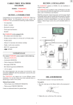
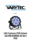
1
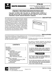
REMOTE SENSORS
MAXIMUM SENSING LOCATIONS PER THERMOSTAT
Indoor Sensing Locations
Thermostat Model
Number
Single
Stage
Total
(Max.)
Thermostat
Onboard
Sensor
Remote
Sensor
Remote Sensor
Priority
Assignment
(LO/AVG/HI)
Allows
Outdoor
Remote
Sensor
1F90-371
1
OFF*
With
1*
-
-
1F96-344
1
OFF*
With
1*
-
-
1F97-1277, -0671
2
ON or OFF
+
1
Yes
Yes***
1F97-371
1
OFF*
With
1*
-
-
1F97-391
1
OFF*
With
1*
-
-
Sensor Set Up
Clip Jumper W922 and
Enable Sensor in Menu
Clip Jumper W922 and
Enable Sensor in Menu
Enable Sensor in Menu
Clip Jumper W922 and
Enable Sensor in Menu
Clip Jumper W922 and
Enable Sensor in Menu
Enable Sensor in Menu
Enable Sensor in Menu
Enable Sensor in Menu
Enable Sensor in Menu
Enable Sensor in Menu
Enable Sensor in Menu
Up to 3
Yes**
Yes
ON or OFF
+
4
1F93-380
+
ON or OFF
4
Up to 3
Yes**
Yes
1F94-371
+
2
Yes***
1
Yes
1F95-1277, -0671
ON or OFF
Staging
Up to 3
ON or OFF
4
Yes
+
Yes**
1F95-371
Yes
4
Up to 3
1F95-377
ON or OFF
Yes**
+
Up to 3
Yes
1F95-391
Yes**
ON or OFF
4
+
*Using a Remote Sensor On This Model Requires the Onboard Thermostat Sensor To Be Off.
**Allows A Sensor Priority of LO, AVG., or HI To Be Assigned To The Onboard Thermostat Sensor In Addition Remote Sensors.
***Accepts One Remote Sensor, Indoor or Outdoor.
REMOTE SENSOR CALCULATED PRIORITY AVERAGE
Consult Maximum Sensing Locations Per Thermostat chart above to determine how many sensors a thermostat will
accept.
Tables 1-3 show how priority (LO, AVG, HI) effects the room temperature calculation. The example below table three shows
the calculation of each remote sensor and how it uses them to arrive at room temperature average.
Table 1: Remote Sensor A configured as a LO priority sensor
Remote
Sensor
SA
Sensor
Priority
LO
Priority
Multiplier
1
Room Temperature
70°F (Sensor Temp.)
Averaging Calculation
1 x 70 = 70 (Priority Multiplier x Room Temp.)
Table 2: Remote Sensor B configured as a AVG priority sensor
Remote
Sensor
SB
Sensor
Priority
AVERAGE
Priority
Multiplier
2
Room Temperature
75°F (Sensor Temp.)
Averaging Calculation
2 x 75 = 150 (Priority Multiplier x Room Temp.)
Table 3: Remote Sensor C configured as a HI priority sensor
Sensor
Priority
HI
Priority
Multiplier
4
Room Temperature
80°F (Sensor Temp.)
Averaging Calculation
4 x 80 = 320 (Priority Multiplier x Room Temp.)
The example below lists three sensors each with a different priority and room temperature. All three sensors are combined in
the calculation to display the average temperature. The priority multiplier shown in the tables above causes a sensor with
low priority to carry less weight in the calculated average. A sensor with a HI priority setting contributes more to the calculated average. Assume that the building in which the thermostat is located has three indoor remote sensors (SA, SB, SC)
that have different room temperatures (70, 75, 80). The calculated average will be displayed as the room temperature
shown in the example below.
Example: Remote Sensors A, B, and C configured as a LO, AVG, and HI priority sensors
Remote
Sensor
SA
SB
SC
Sensor
Priority
LO
AVERAGE
HI
Priority
Multiplier
1
2
4
Room Temperature
70°F (Sensor Temp.)
75°F (Sensor Temp.)
80°F (Sensor Temp.)
Averaging Calculation
1 x 70 = 70 (Priority Multiplier x Room Temp.)
2 x 75 = 150 (Priority Multiplier x Room Temp.)
4 x 80 = 320 (Priority Multiplier x Room Temp.)
Avg. Calc. (540)/Sum Priority Mult. (7)
540/7 = 77°F (Calculated Displayed Temp.)
www.white-rodgers.com
165
TECHNICAL HELP
Remote
Sensor
SC
REMOTE SENSOR
TROUBLESHOOTING
REMOTE SENSORS
Troubleshooting Chart
To function correctly and read temperature accurately, the thermostat must have constant 24-volt power. If the thermostat
temperature is steadily dropping, reading low, or reads 08°, or displays – – – (3 dashes) when a remote sensor is installed,
it can be traced to one of the three following conditions.
Condition
Test
Comments
1. Loss of 24-volt power. On models with batteries, remove the batteries and re-install
thermostat. If the display is blank, check heating and cooling
system to determine why 24-volt power is absent.
For the sensor to read correctly,
the 24-volt system power must
be present. Some systems may
require an isolation relay* to
provide constant power to the
thermostat. Limit or safety
devices in the equipment can
also cause a power interruption.
2. A broken wire on S1,
S2 and S3 or (+, SA, -)
from the thermostat to
the remote.
Repair or replace the 3 wire
shielded cable. Be sure the
remote wire run is not parallel
to line voltage wires that carry
heavy inductive loads, or across
fluorescent light ballasts that
may cause an inductance to be
transmitted to the thermostat.
Disconnect sensor wires at thermostat. Attach a short piece
(2') of three-wire shielded cable to S1, S2 and S3 or (+, SA,
-) on the subbase. Bring the remote sensor to the thermostat
location and attach S1, S2 and S3 or (+, S, -) respectively.
Reattach thermostat. If the temperature begins to climb
(slowly), it is reading correctly. If it reads correctly with the 2'
length but improperly when attached to the wire run, it
indicates a fault in the wire run.
3. A shorted or
Because it is an electronic sensor, there are no Ohm values
damaged remote sensor. to test. If correct conditions as listed in 1 & 2 above and the
temperature stays at or near 08°
08°, it indicates a shorted or
damaged remote sensor.
Replace remote sensor.
Note
Note: Digital thermostats and remote sensors acclimate very slowly to temperature change. It may take an hour or more for
the temperature to acclimate to the room temperature from a low temperature reading as outlined above. To expedite the
room temperature display use the reset instructions listed in the installation instructions for the thermostat model you are
working with. When reset, the thermostat will default to a room temperature of 70° and begin sensing room temperature. Be
sure to reconfigure the installer menu for a remote sensor because the reset function may cancel remote sensing.
* Isolation Relay Wiring
Note: The diagram below shows how to attach an isolation relay to
the “W” or “Y” circuit to provide constant power on power stealing
thermostats. This willl allow the thermostat to operate properly with
a remote sensor.
TECHNICAL HELP
THERMOSTAT
Red Jumper Wire
RH
Line
Voltage
W
Y
Figure 1 shows a single transformer heating/cooling system, with
isolation relays installed in the heating (W) and cooling (Y) circuits.
To simplify the diagram, limit and safety switches are not shown
here, although they will be found either in the low or high voltage
circuit. Limit and safety switches must be retained. Refer to the
equipment manufacturer’s system wiring diagram for the location of
limit and safety switches.
! WARNING
RC
DO NOT REMOVE OR WIRE AROUND LIMIT AND
SAFETY SWITCHES WHEN INSTALLING ISOLATION RELAYS.
24 VAC
Transformer
Heating
System
Cooling
System
Figure 1. Wiring for single transformer systems
166
www.white-rodgers.com
REMOTE SENSOR
WIRING
REMOTE SENSORS
Note
Note: When using shielded cable, connect shield of 18 or
20 gauge 3 connector cable to - or S3 on thermostat
subbase.
Remote Sensor
S1 S2 S3
or
+ S -
S1 S2 S3
+
E2
S
–
To + or S1
To S or S2
To - or S3
Thermostat Subbase
Single Stage Thermostat Remote Sensor Wiring (F145-1328)
Troubleshooting Chart
Note
Note:
When
using
shielded
cable, power.
connectIfshield
of 18 or
To function correctly and read temperature accurately, the thermostat
must
have
constant
24-volt
the thermostat
gaugesensor
3 connector
cable it
to can
- orbe
S3traced
on thermostat
temperature is steadily dropping, reading low, or reads 08° when a 20
remote
is installed,
to one of the
subbase.
three following conditions.
Test
Remote Sensor
1. Loss of 24-volt power. On models with batteries, remove the batteries and re-install
thermostat. If the display is blank, check heating and cooling
system to determine why 24-volt power is absent.
Thermostat Subbase
2. A broken wire on S1,
S2 and S3 or (+, SA, -)
from the thermostat to
the remote.
Outdoor Probe
If connecting
3. A shorted
or
outdoor service
E2
+
S
Disconnect
sensor
wires
at thermostat. AttachToa+short
or S1 piece
Remote
Outoor
Sensor
S or
(2') of three-wire shielded cable to S1, S2 andToS3
orS2
(+, SA,
- orthermostat
S3
-) on the subbase. Bring the remote sensor toTothe
location and attach S1, S2 and S3 or (+, S, -) respectively.
Reattach thermostat. If the temperature begins to climb
(slowly), it is reading correctly. If it reads correctly with the 2'
length but improperly
when attached to the wire run, it
+ S –
indicates a fault in the wire run.
E2
Because it is an electronic sensor, there are no Ohm values
To + If correct conditions as listed in 1 & 2 above and the
damaged remote sensor. to test.
To OT
temperature
stays at or near 08°
08°, it indicates a shorted or
To damaged remote sensor.
Comments
For the sensor to read correctly,
the 24-volt system power must
be present. Some systems may
require an isolation relay to provide constant power to the
thermostat.
Limit or safety
–
devices in the equipment can
also cause a power interruption.
Repair or replace the 3 wire
shielded cable. Be sure the
remote wire run is not parallel
to line voltage wires that carry
heavy inductive loads, or across
fluorescent light ballasts that
may cause an inductance to be
transmitted to the thermostat.
Replace remote sensor.
Staging Multi-Stage or Heat Pump Touchscreen Thermostat (1F95-1277) Indoor/Outdoor Remote
Sensor
Wiringvery
(F145-1328/F145-1378)
Note
Note: Digital thermostats and remote sensors
acclimate
slowly to temperature change. It may take an hour or more for
the temperature to acclimate to the room temperature from a low temperature reading as outlined above. To expedite the
room temperature display use the reset instructions
listed in the installation
instructions for the thermostat model you are
Troubleshooting
Chart
working with. When reset, the thermostat will default to a room temperature of 70° and begin sensing room temperature. Be
function correctly and read temperature accurately, the thermostat must have constant 24-volt power. If the thermostat
sure toToreconfigure
the installer menu for a remote sensor because the reset function may cancel remote sensing.
temperature is steadily dropping, reading low, or reads 08° when a remote sensor is installed, it can be traced to one of the
three following conditions.
Condition
Test
1. Loss of 24-volt power. On models with batteries, remove the batteries and re-install
thermostat. If the display is blank, check heating and cooling
system to determine why 24-volt power is absent.
www.white-rodgers.com
Comments
For the sensor to read correctly,
the 24-volt system power must
be present. Some systems may
require an isolation relay to provide constant power to the
thermostat. Limit or safety
devices in the equipment can
also cause a power interruption.
167
TECHNICAL HELP
Condition
REMOTE SENSOR
WIRING
Note
Note: When using shielded cable, connect shield of 18 or
20 gauge 3 connector cable to - or S3 on thermostat
subbase.
SA SB SC OT
Remote Outdoor Sensor Base
+ Terminals
L PH D SA SB SC OT
- Terminals
E
C
R W3 W2 E2 W1 Y2 Y1 B
A1
P
O
G
Thermostat Subbase
E2
Outdoor Probe
+
S
–
To +
To OT
To -
Remote Indoor Sensor A
Remote Indoor Sensor B
E2
+
S
–
E2
+
S
Remote Indoor Sensor C
–
E2
To To SA
To To SB
To +
To +
+
S
–
To +
To SC
To -
Staging Thermostat Multi-Stage or Heat Pump Indoor/Outdoor Remote Sensor Wiring
(F145-1328/F145-1378)
Note
Note: When using shielded cable, connect shield of 18 or
20 gauge 3 connector cable to - or S3 on thermostat
subbase.
Remote Sensor
Thermostat Subbase
E2
TECHNICAL HELP
Remote Sensor
Outdoor Probe
If connecting
outdoor service
E2
+
S
+
S
–
To + or S1
To S or S2
To - or S3
–
To +
To OT
To -
Single Stage (1F97-1277) TouchscreenThermostat Indoor/Outdoor Remote Sensor Wiring
(F145-1328/F145-1378)
168
www.white-rodgers.com