1
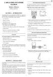
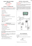
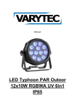
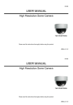
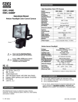
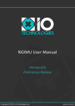
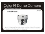
CCTV Camera Manual
Table of Contents
Model configuration
Model configuration
Precautions
Name of each part and Functions
- Front
- Back
2
3
4-5
6-11
Connection
1. Lens
1) How to use a Fixed Iris lens
2) How to use a DC Iris lens
3) How to use a Video Iris lens
4) How to connect an Auto Iris lens
2. How to adjust C/CS Mount
3. How to connect Power
4. How to connect Monitor
12
12-13
13
13-14
15
16
17
Color Camera
■ STD-Res Series
(400 TV Lines, 0.01 Lux/F1.2)
DC12V Only
DC12V~AC24V, Non polarity Dynamic power input
AC230V (AC200~AC240V)
■ STD-Res EX-view Series (400 TV Lines, 0.001 Lux/F1.2 with EX-view HAD CCD)
DC12V Only
DC12V~AC24V, Non polarity Dynamic power input
AC230V (AC200~AC240V)
■ Hi-Res Series (500 TV Lines, 0.03 Lux/F1.2)
DC12V Only
DC12V~AC24V, Non polarity Dynamic power input
AC230V (AC200~AC240V)
■ Hi-Res EX-view Series (500 TV Lines, 0.001 Lux/F1.2 with EX-view HAD CCD)
DC12V Only
DC12V~AC24V, Non polarity Dynamic power input
AC230V (AC200~AC240V)
■ Option
1. IR Sensitive for Day & Night application : Model nr + IR
2. Flickerless Function : Model nr + FL
B/W Camera
Specification
- Color Camera
- B/W Camera
Trouble shooting guide
Note
18
19
20-21
22
Please study the manual thoroughly in order to get the best
performance from the camera.
1
■ STD-Res Series
(420 TV Lines, 0.05 Lux/F1.2)
DC12V Only
DC12V~AC24V, Non polarity Dynamic power input
AC230V (AC200~AC240V)
■ Hi-Res Series (600 TV Lines, 0.1 Lux/F1.2)
DC12V Only
DC12V~AC24V, Non polarity Dynamic power input
AC230V (AC200~AC240V)
■ Hi-Res EX-view Series (600 TV Lines, 0.001 Lux/F1.2 with EX-view HAD CCD)
DC12V Only
DC12V~AC24V, Non polarity Dynamic power input
AC230V (AC200~AC240V)
This unit has been tested and proved to comply with the limits of FCC rules
and CE regulation.
2
Warning !
Name of each part & Functions
☞ To prevent the risk of fire or shock hazard, do not expose this
camera to water.
Front
☞ Installation of this unit should be carried out by a qualified personnel
and should conform to the local codes.
Precautions
1. Do not drop or shake the carton severely.
The box cannot give perfect protection against heavy shocks.
2. Do not touch the CCD glass by hand, as this may give a blurred picture.
3. Do not expose the camera to water or other liquids.
It can cause fire or electric shock. If water or other liquids contaminate
the unit, dry it quickly as it can corrode the electrical components inside.
4. Do not install the camera in the wet area or area of high humidity without
adequate protection.
Moisture can corrode the electrical components inside.
5. Do not turn the camera to face strong light.
Direct sunlight or strong reflected light can cause blooming or smearing
of the picture.
6. Do not install or use the camera in an environment of extreme temperature.
In temperatures of below -10°C use an external housing with heater built
in. In a temperatures of over +60°C, cool the camera with ventilation
apparatus.
7. Do not disassemble the camera.
There are no user serviceable parts inside.
3
1. CCD Protection Cover
Leave the cover in place when the lens is not installed. Take it off to fit the
lens.
2. C&CS mount
This holder moves back and forth by sliding the adjustment lever forwards
or backwards.
This mechanism is designed for the purpose of using all types of C-Mount
or CS-Mount lenses of different manufacturers. Mount the lens on the
holder firmly. It is set to CS-Mount position at the factory. Loosen the
adjustment lever by turning it counter clockwise a little bit in order to adjust
the C&CS mount holder. Set the focus and lock the lever.
3. Adjustment Lever
4. Flange back focus alignment area for C-Mount lens
The mount offers 0.5mm of extra tolerance to enable any type of nonstandard C-Mount lens to be focused. Loosen the adjustment lever by
turning it counter clockwise a little bit for fine tune focus.
5. Flange back focus alignment area for CS-Mount lens
The mount offers 0.5mm of extra tolerance to enable any type of nonstandard CS-Mount lens to be focused. Loosen the adjustment lever by
turning it counter clockwise a little bit for fine tune focus.
4
6. Mounting the Bracket Holder
Can be attached either on the top or on the bottom. Assemble it with the
screws provided. (3 EA)
Back -Color
DC 12V/AC 24V
Line Lock
3. Video Out Connector
(BNC Female)
1. 6Way Dip Switch
7. Auto iris lens connector
Please refer to page 13, 14 of this manual for the wiring specification.
4. Power Indicator
2. Power Input
Terminal
8. Iris mode select switch
ES : Electronic auto iris, VI : Video iris, DC : DC Iris
ES mode is used with manual iris lenses. In ES mode the camera controls
the electronic shutter automatically from 1/50 to 1/100,000
sec.(PAL/CCIR)or 1/60 to 1/100,000 sec.(NTSC/EIA).
ES mode with a Manual iris lens is suitable for indoor surveillance. Select
the slide SW to the ES position.
5. Line Lock / White
Balance Push button
DC 12V
AC 230V Power Cord
For outdoor use, ES mode is not sufficient. In this case an Auto Iris lens of
either Video driven type or DC driven type is recommended. Move the slide
SW to VI position for the Video iris lens or move it to DC position for the DC
Iris lens. When VI or DC mode is selected, the electronic shutter speed is
fixed to 1/50sec(PAL/CCIR) or 1/60sec(NTSC/EIA).
9. DC Level control for DC Iris lens.
It is used for controlling the video output level of the DC driven auto iris
lens.
* To make the image brighter, turn the pot clockwise.
* To make the image darker, turn the pot counter clockwise.
1-1. 6 Way DIP Switch
DIP Switch configuration (24V AC LineLock, 230V AC LineLock only)
No.
ON
OFF
1 (Phase Push SW up/down)Line Lock Mode
Internal Mode
2 OFF
ON
Manual White Balance
Auto White Balance
3 ON (Adjust the Push Button Up/Down) OFF (No need to Adjust the Push Button)
4
5
6
=0.45
=1.0
AGC Max : 26dB
AGC Normal : 20dB
BLC OFF
BLC ON
DIP Switch configuration (DC 12V only)
No.
ON
OFF
1 OFF
ON
Auto White Balance
Manual white Balance
2 ON (Adjust the Push Button Up/Down) OFF (No need to Adjust the Push Button)
=0.45
=1.0
3
AGC Normal : 20dB
AGC Max : 26dB
4
5
6
5
BLC OFF
BLC ON
N.C
N.C
6
* Color 6 Way Dip Switch Functions
Sync Mode Selection(L/L
BLC (Back Light Compensation) ON / OFF (BLC
INT)
* INT(Internal Sync) Mode
This mode is used when the camera is installed outoor with one camera to one
monitor operation.
ON)
Under bright lighting conditions from behind the subject, the camera will close the
iris automatically. Select BLC mode to counteract this. In normal lighting
conditions, select BLC to OFF. It is set to OFF at the factory.
1-2. Power Input Terminal
* L/L(Line Lock) Mode : To work with other cameras using 24VAC and 230VAC
power, it is required to synchronize the video signals in order to remove picture
fluctuation problems. In the case of one camera with one monitor under
fluorescent lighting, the picture is affected by the 24VAC and 230VAC power
frequency in INT mode. A flickering picture may result from this condition. Set Dip
S/W to L/L mode to remove this problem. It is set to L/L at the factory.
This terminal provides connections for DC 12V or AC 24V.
It is not polarity sensitive. The unit has a wide power tolerance, within DC
10V~DC 40V or within AC 15V~AC 30V. It is not a special requirement to use a
regurated power supply, but using a regurated supply is recommended.
1-3. Video Out Jack (BNC Female)
Connect Coaxial cable from this BNC connector to the monitor. Use a high quality
coaxial video cable to ensure good picture quality over long distances.
White Balance Control
W
W
* WBA (White Balance Auto) mode ( B
B)
A
M
The camera controls the white balance automatically. It is recommended for most
applications. It is set to WBA at the factory.
W
W
* WBM (White Balance Manual) Mode( B
B)
A
M
White balance is controlled manually under this mode by adjusting the push
button up or down. It is not used for normal applications. It may needed for
special conditions or when the camera is used under special lighting. The back
ground of the picture may become red or blue under manual adjustment.
Gamma Correction Select Mode ( =1.0
0.45)
Select 1.0 when the picture needs to be darker in contrast.
It is set to 0.45 at the factory.
Option : Flickerless Select Mode (
FL OFF)
FL ON(NTSC:1/100 sec, PAL:1/120 sec)
Automatic Gain Control (MAX
AGC)
Use this mode for dark illumination or at night. If the MAX(AGC Max) is selected
the camera increases the video signals to maximum so that the picture looks
brighter.
At MAX mode, unnecessary noise is increased also and the picture may display
noise on the screen. This is normal. It is set to AGC at the factory.
7
1-4. Power Indicator
Red power lamp turns on when the power is properly supplied.
1-5. Vertical Phase Adjustment Push Button (Line Lock mode)
White Balance Push button
The up/down push buttons control V phase at L/L mode and control manual white
balance at the WBM mode.
◆ At the L/L Mode
When the unit is used with system equipment and other cameras, it is required to
synchronize the Vertical Phase between the cameras when using 24VAC. It is
recommended to use a multi-channel oscilloscope for correct adjustment.
Push the buttons once at a time up or down when vertical phase of the unit does
not match the other cameras or system equipment.
◆ At the WBM (White Balance Manual) Mode
Adjust the white balance with the push buttons when the camera is used with the
special lighting such as sodium lamps. Usually it is not used for security
applications.
These two functions cannot be adjusted at the same time. Adjust each mode in
turn.
8
Back -B/W
* B/W 4 Way Dip Switch Functions
DC 12V/AC 24V
Line Lock
Sync Mode Selection(L/L
3. Video Out Connector
(BNC Female)
1. 4Way Dip Switch
4. Power Indicator
2. Power Input
Terminal
5. V.R
AC 230V Power Cord
Line Lock Cord
DC 12V
INT)
* INT(Internal Sync) Mode
This mode is used when the camera is installed outoor with one camera to
one monitor operation.
* L/L(Line Lock) Mode : To work with other cameras using 24VAC power, it is
required to synchronize the video signals in order to remove picture
fluctuation problems. In the case of one camera with one monitor under
fluorescent lighting, the picture is affected by the 24VAC power frequency in
INT mode. A flickering picture may result from this condition. Set Dip S/W to
L/L mode to remove this problem. It is set to L/L at the factory.
Gamma Correction Select Mode ( =0.45
1.0)
Select 1.0 when the picture needs to be darker in contrast.
It is set to 0.45 at the factory.
Automatic Gain Control (AGC
MAX)
Use this mode for dark illumination or at night. If the MAX(AGC Max) is
selected the camera increases the video signals to maximum so that the
picture looks brighter.
At MAX mode, unnecessary noise is increased also and the picture may
display noise on the screen. This is normal. It is set to AGC at the factory.
1. 4 Pin DIP Switch
DIP Switch configuration (24V AC LineLock)
No.
OFF
1
INT
2
=0.45
3
BLC OFF
4
AGC Normal : 20dB
DIP Switch configuration (DC 12V & 230V AC)
No.
OFF
1
=0.45
2
BLC ON
3
AGC Normal : 20dB
4
N.C
9
ON
L/L
=1.0
BLC ON
AGC Max : 32dB
BLC (Back Light Compensation) ON / OFF (BLC
OFF)
Under bright lighting conditions from behind the subject, the camera will close
the iris automatically. Select BLC mode to counteract this. In normal lighting
conditions, select BLC to OFF. It is set to OFF at the factory.
ON
=1.0
BLC OFF
AGC Max : 32dB
N.C
10
2-2. Power Input Terminal
Connection
This terminal provides connections for DC 12V or AC 24V.
It is not polarity sensitive. The unit has a wide power tolerance, within DC
10V~DC 40V or within AC 15V~AC 30V. It is not a special requirement to use
a regurated power supply, but using a regurated supply is recommended.
2-3. Video Out Jack (BNC Female)
Connect Coaxial cable from this BNC connector to the monitor. Use a high
quality coaxial video cable to ensure good picture quality over long distances.
1. Lens
It is recommended to use a good quality lens to improve the picture quality
under low light conditions.
The camera is built with a universal mounting mechanism on which any type
of lens can be used.
* Lens is not supplied with camera.
How to use a Manual Iris lens
2-4. Power Indicator
Red power lamp turns on when the power is properly supplied.
2-5. Vertical Phase Adjustment V.R (Line Lock mode)
* In this set-up the camera does not control the iris. Instead the camera
adjusts the picture automatically for light changes. Set the Iris mode select
switch to ES (Electronic Shutter) position.
◆ At the L/L Mode
When the unit is used with system equipment and other cameras, it is
required to synchronize the Vertical Phase between the cameras when using
24VAC. It is recommended to use a multi-channel oscilloscope for correct
adjustment.
Adjust vertical phase of the unit with V.R to match with other cameras or
system equipment.
* Please make sure to check this before operation. When the S/W is
positioned at the VI or DC mode, the electronic shutter will be off and will not
control the picture.
How to use a DC Iris lens
11
12
2
* Set the iris mode select switch to DC (DC driven automatic iris Control)
position.
* In this mode, the iris is controlled automatically to react to DC signals from
the camera.
* Please make sure to set S/W to DC position before you operate the camera
with a DC lens.
* DC level control is on the side of the camera. Please do not touch the DC
Level control when using a fixed or Video iris type of lens.
* The camera is set to DC at the factory. Adjust the pot up or down only when
you need the picture to look brighter or darker depending on the situation.
Generally there is no need to adjust the level.
* Remove the cover of the auto iris plug
connector(supplied with the camera) and
solder the lens cable to the pins as per
the following configuration:
How to use a Video Iris lens
* Set the iris mode select switch to VI (Video signal driven Automatic Iris)
position.
* In this mode the lens controls itself automatically to react to Video signals
from the camera.
* Video type
* Please make sure to set S/W to VI position before you operate the unit with
a Video type auto iris lens. Level control is on the side of the lens .
How to connect an Auto Iris lens (DC / Video)
* Take off the insulation of the lens cable as shown on the drawing.
(approx. 8mm)
* Take off the insulation of the inner cable as shown on the drawing.
(approx. 2mm)
13
1
* DC type
* Video type
* DC type
No. 1 Pin --- Red(Power source)
No. 2 Pin --- N.C
No. 3 Pin --- Yellow(Video Signal)
No. 4 Pin --- Black(GND)
No. 1 Pin --- DAMP No. 2 Pin --- DAMP +
No. 3 Pin --- Drive +
No. 4 Pin --- Drive -
Remove the Protection Cap and attach the lens to
the camera.
Set the Iris mode select switch, S/W to VI, ES or DC
position according to the type of lens.
Connect the lens plug to the
auto iris socket located on
the left side of the camera.
14
2
2. How to adjust C&CS Mount
3. How to connect power
3-1. Please check the model and power specification before connecting
the power.
3-2. AC24V power
The camera has a
common power input
connector for both
12VDC and 24VAC.
The power input is
non polarized.
Loosen the lens mount holder by turning the adjustment lever clockwise.
Pull the adjustment lever backward and fix it on the “CS” position.
Turn the lever counter clockwise to tighten.
Push the lever forward and fix it on the “C” position.
Turn the lever clockwise to tighten.
C-Mount
CS-Mount
Hold the levers at both side together and move the lens mount holder forward
or backward.
Color
B/W
3-3. The unit has a
wide power tolerance,
within DC 10V ~ DC
40V or within AC 15V
~ AC 30V.
3-4. DC 12V power
Use regulated DC
12V power supply
ONLY. The power
input is non polarized.
3-5. AC 230V power
Use an AC 230V
power source.
Connect the power
plug to the outlet
directly.
WARNING !
CONNECT POWER ONLY AFTER INSTALLATION IS COMPLETED.
Refer to page 4 for any additional information.
15
1
16
2
4. How to connect to monitor
Specification (Color)
4-1. Connect the Video out jack to the Video In jack on the monitor.
- Use good quality shielded coaxial video cable to avoid noise interference.
- Connect the cable with the power turned off.
Camera Back
Monitor
- When the camera is used with multi-channel equipment or with more than 2
monitors, please set impedance level switch on the interim equipment /
monitors to HI-Z position and make sure to set the last monitor to 75
position.
INTERIM EQUIPMENTS
OR MONITOR
CAMERA
17
1
LAST MONITOR
MODEL
STD-Res Series
Hi-Res Series
Image sensor
1/3" SONY HAD IT CCD Option : 1/3" EX-View HAD CCD, SONY
Effective Pixels
NTSC:512(H)X492(V) PAL:500(H)X582(V) NTSC:768(H)X494(V) PAL:752(H)X582(V)
H.Resolution
400 TV Lines
500 TV Lines
Synchronizing system
Internal
Internal/Line Lock Line Lock Only
Internal
Internal/Line Lock Line Lock Only
Scanning system
NTSC 525 Lines PAL 625 Lines
2:1 Interlaced
Video output
1.0Vp-p Composite. 75 Ohms
S/N ratio
More than 50 dB (AGC Off)
Min. Illumination
STD : 0.01 Lux at F1.2
High-Res : 0.03 Lux at F1.2
EX-View : 0.001 Lux at F1.2
BLC
ON/OFF by Dip Switch
Shutter Speed
NTSC : 1/60~1/100,000 sec
PAL : 1/50~1/100,000 sec
Gamma correction
Standard
0.45
Switchable
1.0 by Dip Switch
White Balance
Standard 2100°K ~ 9100°K Auto Manual setting by Dip S/W & Up/Down by Push BTN
Gain Control
Standard : 8dB~30dB Auto
Maximum by Dip switch
Smear Effect
0.005%
MTBF
80,000 hours
Power source
DC12V
DC12V-AC24V Dynamic
AC230V
DC12V
DC12V-AC24V Dynamic
AC230V
Operating current
150mA, 110mA
30mA
130mA
150mA, 110mA
30mA
130mA
Lens
C-Mount (17.5mm Frange back) ~ CS-Mount (12.5mm Frange back) & Fine focus 1.0mm
Iris Control
Video Iris/ESC/DC Iris
Operating Temperature
14° F~122° F ( -10° C~ + 50° C )
Humidity
Within 90% RH
Measurement(mm)
50(W) x 50(V) x 115(L)
Weight(Approx.g)
410
310
410
310
310
310
Yes
IR Sensitivity
Yes
Optional Audio
Features Dual Power 12~24 12V DC Only
Line Lock
ON/OFF
BLC
STD/MAX
AGC
Dip S/W
0.45/1.0
Gamma
Control
WBA / WBM
Line Lock
BNC
Video Out
Red LED
Power Indicator
Rear Power Input terminal Screw Joint
Pannel Line phase push BTN
W/B adjust push BTN Up/Down
Dip S/W
6 Way
Auto Iris jack
4Pin Jack
Side
Iris Mode Slide S/W
VI ES DC
Pannel
DC Iris Adjust volume
DC Level
Yes
Yes
Yes
Yes
Yes
Yes
Yes
Yes
Yes
Yes
Yes
Yes
12V DC Only
Yes
Yes
Yes
Yes
ON/OFF
ON/OFF
ON/OFF
ON/OFF
ON/OFF
STD/MAX
STD/MAX
STD/MAX
STD/MAX
STD/MAX
0.45/1.0
0.45/1.0
0.45/1.0
0.45/1.0
0.45/1.0
White Balance Auto/WB Manual adjustment
ON/OFF
ON/OFF
BNC
BNC
BNC
BNC
BNC
Red LED
Red LED
Red LED
Red LED
Red LED
Screw Joint 230V AC VDE Code Screw Joint Screw Joint 230V AC VDE Code
Up/Down
Up/Down
Up/Down
Up/Down
Up/Down
Up/Down
Up/Down
Up/Down
Up/Down
6 Way
6 Way
6 Way
6 Way
6 Way
4Pin Jack
4Pin Jack
4Pin Jack
4Pin Jack
4Pin Jack
VI ES DC
VI ES DC
VI ES DC
VI ES DC
VI ES DC
DC Level
DC Level
DC Level
DC Level
DC Level
18
2
Specification (B/W)
MODEL
Image sensor
Effective Pixels
H.Resolution
Synchronizing system
Scanning system
Video output
S/N ratio
Min. Illumination
Trouble Shooting Guide
STD-Res Series
1/3" Interline CCD, SONY
Hi-Res Series
1/3" Interline CCD, SONY
Option : EX-View HAD CCD Version
EIA:512(H)X492(V) CCIR:500(H)X582(V) EIA:768(H)X494(V) CCIR:752(H)X582(V)
420 TV Lines
600 TV Lines
Internal
Internal/Line Lock
Internal
Internal
Internal/Line Lock
Internal
EIA 525 Lines CCIR 625 Lines
2:1 Interlaced
1.0Vp-p Composite. 75 Ohms
More than 50 dB (AGC Off)
0.1 Lux at F1.2
Option : 0.001 Lux at F1.2 (EX-View HAD CCD version)
0.05 Lux at F1.2
BLC
ON/OFF by Dip Switch
Shutter Speed
EIA : 1/60~1/100,000 sec
CCIR : 1/50~1/100,000 sec
Gamma correction
Standard
0.45
Switchable
1.0 by Dip Switch
Gain Control
Standard : 4dB~30dB Auto
Maximum by Dip switch
Smear Effect
0.005%
MTBF
80,000 hours
Power source
DC12V
DC12V-AC24V ( 4V) Dual AC230V( 30V)
DC12V
DC12V-AC24V ( 4V) Dual AC230V( 30V)
Operating current
110mA
100mA, 50mA
20mA
110mA
100mA, 50mA
20mA
Lens
C-Mount (17.5mm Frange back) ~ CS-Mount (12.5mm Frange back) & Fine focus 1.0mm
Video Iris/ESC/DC Iris
Iris Control
Operating Temperature
14° F~122° F ( -10° C~ + 50° C )
Humidity
Within 90% RH
Measurement(mm)
50(W) x 50(V) x 115(L)
Weight(Approx.g)
310
410
310
310
410
310
ON/OFF
ON/OFF
Line Lock
0.45/1.0
0.45/1.0
0.45/1.0
0.45/1.0
0.45/1.0
0.45/1.0
Dip S/W Gamma
ON/OFF
ON/OFF
ON/OFF
ON/OFF
ON/OFF
ON/OFF
Control BLC
STD/MAX
STD/MAX
STD/MAX
STD/MAX
STD/MAX
STD/MAX
AGC
Video Out
BNC
BNC
BNC
BNC
BNC
BNC
Power Indicator
Red LED
Red LED
Red LED
Red LED
Red LED
Red LED
Rear
Power Input terminal Screw Joint Screw Joint 230V AC VDE Code Screw Joint Screw Joint 230V AC VDE Code
Pannel
Phase V.R
YES
YES
Dip S/W
4Way Slide 4Way Slide 4Way Slide 4Way Slide 4Way Slide 4Way Slide
Auto Iris jack
4Pin Jack
4Pin Jack
4Pin Jack
4Pin Jack
4Pin Jack
4Pin Jack
Side
Iris Mode Slide S/W
VI ES DC
VI ES DC
VI ES DC
VI ES DC
VI ES DC
VI ES DC
Pannel
DC Iris Adjust volume
DC Level
DC Level
DC Level
DC Level
DC Level
DC Level
19
1
If the unit continues to be fault after the following adjustments please consult
your dealer.
When the picture is not displayed on the monitor
- Please check if the AC-DC power unit is plugged into the AC power outlet
firmly
- Please check if there are any misconnection’s in the cabling.
- Please check if the IRIS mode select switch is set to the correct position i.e. to
the DC mode for the DC driven auto iris lens or VI mode for the Video driven
auto iris lens.
When the picture is blurred
- Please check if the lens is contaminated. Please clean the lens surface
(on both sides) gently with a soft cloth or tissue.
- Please check if the lens is focused properly.
- When you use a manual iris lens, the iris select switch should be
positioned to the ES mode.
- Please check if the monitor is set to brightly. Adjust the brightness or
contrast level on the monitor correctly.
When the color displayed on the monitor is not correct(for Color)
- Please check if the White Balance switch is set to WBM position.
White balance is controlled automatically under the WBA mode for most
situations. When the camera is used under special lighting conditions,
please refer to page 7 in this manual.
- Please check if the monitor’s color adjustment is set correctly.
When the picture is too dark
- Please check if the monitor’s contrast is set too dark.
- Please check if the Gamma select switch is set to 1.0 on the 6th pin of the
DIP switch. If it is please move it to the 0.45 position. Gamma 1.0 position
is recommended for use with a LCD monitor.
- Please check if the camera is positioned toward a door or window.
Please set BLC ON is these conditions.
20
2
Note
When the picture is too bright
- Please check if the monitor’s brightness control is get too high.
- Please check if the camera is set to BLC ON under normal lighting
conditions.( i.e. when the camera is not pointed towards a brightly lit area)
Please move the BLC select switch to the BLC OFF position.
When there is noise on the picture in dark illumination conditions
- The camera picture becomes noisy under AGC MAX mode in order to
increase the video gain in poor lighting conditions. Please move the AGC
switch to OFF position if it is not required.
When the picture is not clear on the monitor
- Please check if the monitor is set up correctly.
- Please check if the camera is pointer towards an area where too much
light comes in. Adjust the direction of the camera in this case.
- Please check if the back focus of the lens is set correctly.
When the picture is flickering
- Please check if the camera is pointed at fluorescent lighting or bright
sunlight. Use a visor or adjust the direction of the camera in this case.
- Please check if the Auto iris lens is selected correctly on the IRIS mode
select switch. Please move the Iris mode switch to DC position when you
use a DC type auto lens or move it to the VI position when you use a
Video type auto iris lens.
- When you don't use an auto iris lens, please move the iris select switch to
the ES position
When the picture is distorted
- Please check if the lens is defective and replace the lens in this case.
- Please check if the camera is PAL/CCIR(50Hz) in an NTSC/EIA(60Hz)
area or vice versa.
21
1
22