1
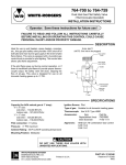
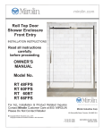
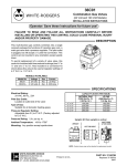
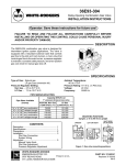
50E47
WHITE-RODGERS
Hot Surface Ignition Control
INSTALLATION INSTRUCTIONS
Operator: Save these instructions for future use!
FAILURE TO READ AND FOLLOW ALL INSTRUCTIONS CAREFULLY BEFORE
INSTALLING OR OPERATING THIS CONTROL COULD CAUSE PERSONAL
INJURY AND/OR PROPERTY DAMAGE.
DESCRIPTION
The White Rodgers 50E47 is an automatic gas interrupted ignition control employing a microprocessor to
continually monitor, analyze, and control the proper operation of the gas burner.
Signals interpreted during continual surveillance of the
thermostat and flame sensing element initiate automatic
ignition of the burner, sensing of the flame and system
shut-off during normal operation.
System fault analysis, which quickly shuts off the gas flow,
coupled with automatic re-ignition upon sensing a fault
correction, highlight the control’s capabilities.
PRECAUTIONS
! CAUTION
! GENERAL PRECAUTION
Application of this type of control may cause
flame rollout on initial startup and could cause
personal injury and/or property damage.
Replace only with exact model number, including dash number. Failure to use exact replacement control could cause personal injury and/or
property damage.
If in doubt about whether your wiring is millivolt, line, or low
voltage, have it inspected by a qualified heating and air
conditioning contractor or licensed electrician.
Do not exceed the specification ratings.
To prevent electrical shock and/or equipment
damage, disconnect electric power to system at
main fuse or circuit breaker box until installation
is complete.
Label all wires prior to disconnection when servicing controls. Wiring errors can cause improper and dangerous operation.
This control is not intended for use in locations
where it may come in contact with water. Suitable protection must be provided to shield the
control from exposure to water (dripping, spraying, rain, etc.).
All wiring must conform to local and national electrical
codes and ordinances.
This control is a precision instrument, and should be
handled carefully. Rough handling or distorting components could cause the control to malfunction.
CONTENTS
Description ......................................................... 1
Precautions ........................................................ 1
Specifications ..................................................... 2
Installation .......................................................... 3
Mounting & Wiring
Operation ............................................................ 4
R
WHITE-RODGERS DIVISION
EMERSON ELECTRIC CO.
9797 REAVIS ROAD
ST. LOUIS, MISSOURI 63123-5398
!
WARNING
Do not use on circuits exceeding specified voltage. Higher voltage will damage control and
could cause shock or fire hazard.
Do not short out terminals on gas valve or primary control to test. Short or incorrect wiring will
damage thermostat and could cause personal
injury and/or property damage.
PART NO. 37-4836B
Printed in U.S.A.
Replaces 37-4836A
9541
SPECIFICATIONS
ELECTRICAL RATINGS:
HUMIDITY RANGE:
To 95% relative humidity (non-condensing)
Input Voltage: 25 VAC 50/60 Hz
Current: 0.2 amp
Relay Contact Ratings:
Valve Relay: 1.5 amp @ 25 VAC 50/60 Hz 0.6 pf
Ignitor Relay: 6.0 amp @ 120 VAC 50/60 Hzresistive
MOUNTING:
Surface mount or 4" x 4" junction box
Timing Specs (see table below for variable timings):
maximum
60 Hz
50 Hz
4.0 sec
7.0 sec
0.8 sec
4.8 sec
8.4 sec
0.96 sec
Flame Current Requirements:
Minimum current to insure flame detection: 2 µa DC*
Maximum current for non-detection: 0.2 µa DC*
Maximum allowable leakage resistance: 100 M ohms
Flame Establishing Time
Standard
Optional
Flame failure Response time:
* Measured with a DC microammeter in the flame
probe lead
Recycle Time: Immediate, or equal to prepurge time
on models with prepurge option.
OPERATING TEMPERATURE RANGE:
-40° to 175°F (-40° to 80°C)
Gases Approved: Natural, Manufactured, Mixed,
Liquid Petroleum, and LP Gas Air Mixtures are all
approved for use.
TIMING SPECIFICATIONS
(all times in seconds unles otherwise noted)
Dash Number
Pre-purge
-1 thru -9
-10 thur -19
-20 thru -29
-30 thru -39
-40 thru -49
-50 thru -59
-60thru -69
-70 thru -79
-101 thru -109
-110 thru -119
-120 thru -129
-130 thru -139
-140 thru -149
-150 thru -159
-160 thru -169
-170 thru -179
-201 thru -209
-210 thru -219
-220 thru -229
-230 thru -239
-240 thru -249
-250 thru -259
-260 thru -269
-270 thru -279
-301 thru -309
-310 thru -319
-320 thru -329
-330 thru -339
-340 thru -349
-350 thru -359
-360 thru -369
-370 thru -379
0
0
30
30
30
30
0
0
0
0
30
30
30
30
0
0
0
0
30
30
30
30
0
0
0
0
30
30
30
30
0
0
Ignitor
Warmup
Period
17
45
17
45
17
45
17
45
17
45
17
45
17
45
17
45
17
45
17
45
17
45
17
45
17
45
17
45
17
45
17
45
Trial for
Ignition
Ignition Activation
Retries
Period
Period
4
4
4
4
4
4
4
4
7
7
7
7
7
7
7
7
4
4
4
4
4
4
4
4
7
7
7
7
7
7
7
7
1
1
1
1
1
1
1
1
4
4
4
4
4
4
4
4
1
1
1
1
1
1
1
1
4
4
4
4
4
4
4
4
0
0
0
0
2
2
2
2
0
0
0
0
2
2
2
2
0
0
0
0
2
2
2
2
0
0
0
0
2
2
2
2
Valve
Sequence
Period
Interpurge
4
4
4
4
12
12
12
12
7
7
7
7
21
21
21
21
4
4
4
4
12
12
12
12
7
7
7
7
21
21
21
21
NOTE: All times are in nominal seconds at 60 Hz. Multiply all timings by 120% at 50 Hz.
Reset time is 2.3 seconds max. at power-up.
On controls with retry option, ignitor warm-up time is increased by 10 seconds on retry
2
0
0
0
0
90
90
60
60
0
0
0
0
90
90
60
60
0
0
0
0
90
90
60
60
0
0
0
0
90
90
60
60
Lockout
Time
21
49
51
79
293
377
203
287
24
52
54
82
302
386
212
296
21
49
51
79
293
377
203
287
24
52
54
82
302
386
212
296
INSTALLATION
WIRING
MOUNTING AND WIRING
!
WARNING
Do not use on circuits exceeding specified voltage. Higher voltage will damage control and
could cause shock or fire hazard.
! CAUTION
To prevent electrical shock and/or equipment
damage, disconnect electric power to system at
main fuse or circuit breaker box until installation
is complete. Failure to earth ground the appliance or reversing the neutral and hot wire connection to the line can cause shock hazard.
Shut off main gas to heating system until installation is complete.
Route and secure all wiring as far from flame
as practical to prevent fire and/or equipment
damage.
The two terminals identified as MV connect to the 36E
model gas valve. Both solenoids in the valve will be in
parallel across these two terminals.
The TH terminal must be connected to the switched 24
volt wire from the thermostat (TH is the same as the W
terminal on most low voltage thermostat systems).
The TR terminal is connected to the 24 volt transformer
return. TR may be grounded either at the transformer
or by a ground wire extended from the terminal TR (TR
is the same as the C terminal on most low voltage
thermostat systems).
The L1 terminal and IGN terminal are connected with a
two-terminal connector on the ignitor leads.
The FP terminal is connected to the flame probe. Maximum recommended wire length to the flame probe is 36
inches.
The GND terminal is a ground and return path for the
flame sensor probe. GND must be reliably connected
to the burner chassis ground.
NOTE
HOT
NEUTRAL
LINE VOLTAGE
All wiring should be installed according to local and
national electrical codes and ordinances.
Limit
The 50E47 control may be mounted on any convenient
surface using two #6 x 5/8 sheet metal screws. If desired,
it is designed to be mounted on a 4" x 4" junction box using
two #8-32 x 5/8" machine screws.
Any orientation is acceptable.
R
MV
Redundant
Valve
Main
Valve
MV
Refer to the wiring diagram and wiring table when connecting the 50E47 control to other components of the
system.
UL approved, 105°C rated 18 gauge min., stranded, 2/64"
thick insulation wire is recommended for all low voltage
safety circuit connections. Refer to 50E47 specification
sheet for recommended terminals to mate with those on
the control.
UL approved 105°C rated 16 gauge min., stranded, 4⁄64”
thick insulation wire is recommended for all line voltage
connections. Refer to 50#47 specification sheet for recommended terminals to mate with those on the control.
Common (C)
50E47
Thermostat
BLACK
The control must be secured to an area that will experience a minimum of vibration and remain below the maximum ambient temperature rating of 175°F. The control is
approved for minimum ambient temperatures of -40°F.
W
Transformer
24 VAC
60 Hz
Class II
WHITE
Replace 50E47 control as a unit - no user serviceable
parts.
TR
TH
FP
Flame Sensor
Probe
GND
L1
Silicon Carbide
Ignitor
IGN
LINE VOLTAGE
LOW VOLTAGE
Following installation or replacement, follow appliance
manufacturer's recommended installation/service instructions to insure proper operation.
3
OPERATION
TYPICAL FURNACE INSTALLATION
In a typical system, a call for heat is initiated by closing the
thermostat contacts. This will energize the 50E47 control.
If the system is equipped with prepurge, the prepurge fan
or interfacing relay is also energized through the thermostat contacts. In the prepurge mode, the 50E47 control will
delay 30 seconds before applying power to the 767A
silicon carbide ignitor. If prepurge is not an option, the
ignitor is powered within one second.
The ignitor is then allowed to warm up for 17 or 45 seconds
depending on the 50E47 control dash number being used
(see Timing Specifications table). Various ignitors on
the market must use the 45-second option to allow them
to fully attain ignition temperatures at low voltage conditions. The W-R 15-second ignitor is especially designed
to heat up quickly at a low voltage condition without
overheating at a high voltage condition. Thus, the W-R 15second ignitor may also be used with a 45-second warmup time without detrimental effects.
At the end of the ignitor warm-up time, both valves in the
36E manifold gas valve are opened. The ignitor will
remain on for an additional one second (ignition activation
period). A four-second ignition activation period is also
available. Flame must be detected within four seconds (a
seven-second trial for ignition period is available as a
separate type). If flame is not detected, both valves are
de-energized, the ignitor is turned off, and the 50E47
control goes into lockout.
After this wait, the ignition sequence is restarted. An
additional 10 seconds is added to the ignitor warm-up
time, so a module with a 17-second warm-up time will
have 27 seconds of ignitor warm-up or a module with a
45-second warm-up time will have 55 seconds of ignitor
warm-up. If this ignition attempt is unsuccessful, one
more retry will be made before lockout.
All 50E47 controls will repeat the ignition sequence for a
total of five recycles if flame is lost within the first 10
seconds of establishment.
If flame is established for more than 10 seconds after
ignition, the 50E47 controller will clear the ignition attempt
(retry) counter. If flame is lost after 10 seconds, it will
restart the ignition sequence. This can occur a maximum
of five times.
During burner operation, a momentary loss of power of 50
milliseconds or longer will de-energize the main gas
valve. When power is restored, the gas valve will remain
de-energized and a restart of the ignition sequence will
begin immediately.
A momentary loss of gas supply, flame blowout, or a
shorted or open condition in the flame probe circuit will be
sensed within 0.8 seconds. The gas valve will de-energize and the control will restart the ignition sequence after
waiting 60 seconds. Recycles will begin and the burner
will operate normally if the gas supply returns, or the fault
condition is corrected, before the last ignition attempt.
Otherwise, the control will go into system lockout.
If the control is locked out, it may be reset by momentary
power interruption of 1⁄20 second or longer. Either the
24 volt thermostat or line voltage may be interrupted.
The 50E47 control may also be equipped with a retry
option, depending on the dash number (see Timing
Specifications table). This provides a 60-second wait
following an unsuccessful ignition attempt (flame not
detected). If the prepurge option is used, the waiting time
becomes 90 seconds (30-second prepurge plus 60-second wait).
If you need further information about this product, please write to
White-Rodgers Division, Emerson Electric Co.
9797 Reavis Road
St. Louis, MO 63123-5398
Attention: Technical Service Department