1
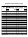
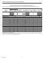
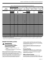
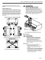
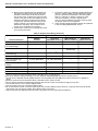
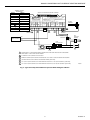
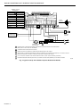
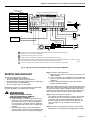
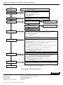
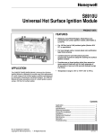
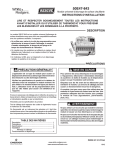
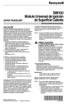
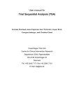
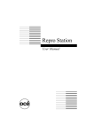
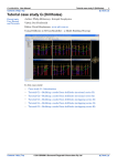
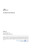
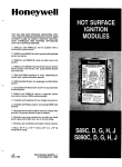
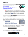
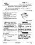
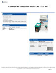
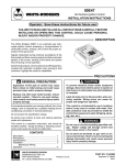
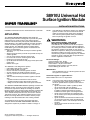
S8910U Universal Hot
Surface Ignition Module
SUPER TRADELINE ®
INSTALLATION INSTRUCTIONS
Installation Instructions for the Trained Service Technician.
APPLICATION
The SUPER TRADELINE® S8910U Universal Hot
Surface Ignition Module is designed to provide easy field
replacement for a wide range of hot surface ignition
modules manufactured by Honeywell, Robertshaw and
White-Rodgers. The S8910U Module provides operating
control of a direct ignition system using a 120 Vac hot
surface igniter. The S8910U replaces existing flame
rectification type hot surface ignition modules with the
following characteristics:
• 120 Vac (up to 5A) timed warmup hot surface ignition
elements.
• Single rod (local sense) or dual rod (remote sense) hot
surface ignition.
• One or three ignition trials per call for heat.
• Four-second or seven-second ignition trials.
• Prepurge of 32 seconds or less.
• Up to 96 seconds between trial purge times (three-trial
mode only).
• Natural or LP gas.
The S8910U is not designed to replace:
• Intermittent pilot ignition controls.
• Direct spark ignition controls.
• Proven 120 Vac hot surface ignition controls.
• 24 Vac element hot surface ignition controls.
• 240 Vac input/120 Vac element hot surface ignition
controls.
• 120 Vac timed warmup hot surface ignition controls
with:
—Ignition trial time shorter than four seconds.
—Ignition trial time longer than twelve seconds.
—Edge connectors rather than male quick-connects.
The SUPER TRADELINE® S8910U package contains the
S8910U control, and easy-to-use instructions, and the
accessories required to adapt the existing hot surface
ignition module. The accessory bag assembly includes the
White-Rodgers adapter, Robertshaw ground lead, four
1/4 in. female .032 quick-connects, one 3/16 in. female
.032 quick-connect, four selection tabs and seven wire
labels. The wiring labels are included to assure proper
marking of the wires attached to the existing module.
A complete list of the specific Honeywell and other
modules that the SUPER TRADELINE ® S8910U is
designed to replace is provided in Tables 1 through 3.
®U.S. Registered Trademark
Copyright © 1996 Honeywell Inc. • All Rights Reserved
NOTE: The S8910U is intended to replace only defective
ignition controls. The service technician should
make sure that the other parts of the appliance
and control system operate safely and reliably
before replacing the ignition control.
WARNING
EXPLOSION HAZARD. CAN CAUSE
INJURY OR EQUIPMENT DAMAGE.
The S8910U can only be used for direct replacement. Check Tables 1 through 3 before replacing
an existing hot surface module with the S8910U. If
the existing module is not listed, do not use the
S8910U to replace it. Always use the selection tab
specified in Tables 1 through 3 for the existing
module being replaced. Replacing with an unlisted
module or using a selection tab not specified can
result in appliance malfunction.
Electrical Ratings:
Control Voltage: 24V, 60 Hz.
Maximum Valve Contact Rating: 2A.
Current Draw: .4A plus valve load.
Hot Surface Igniter Voltage: 120 Vac, 60 Hz.
Contact Rating At 120 Vac: 5A.
IMPORTANT
Use the S8910U only in a 60 Hz system. Be sure
the system is not 50 Hz.
Hot Surface Igniter or Igniter-Sensor:
Norton Model 201 or 271 or equivalent.
NOTE: If an igniter other than a Norton Model 201 or 271
is used, the igniter must meet the following
minimum specifications required over the life of
the igniter:
• Igniter must reach 1832°F (1000°C) within
34 seconds with 102 Vac applied.
• Igniter must maintain at least 500M ohms
insulation resistance between the igniter
leadwires and the igniter mounting bracket.
• Igniter must not develop an insulating layer
on its surface (over time) that would prevent
flame sensing.
• Igniter surface area immersed in flame must
not exceed one-fourth of the grounded area
immersed in flame. This would prevent flame
sensing.
• Igniter current draw at 132 Vac must not
exceed 5A.
X-XX UL
69-0845-2
S8910U UNIVERSAL HOT SURFACE IGNITION MODULE
Ignition Sequence:
The number of trials for ignition and trial time are determined by the selection tab. See Table 1. If a selection tab
is not installed, the module will operate at four seconds
trial time and one ignition trial.
Sensor:
A separate sensor is required for remote sensing applications.
Wiring:
Use the existing appliance wiring. If repair or replacement
of leadwires is required, follow the instructions on the
appliance label. Use the included quick-connect terminals
according to the instructions.
Ambient Operating Temperature:
-40°F to +175°F (-40°C to +79°C).
Accessory Bag Assembly:
• White-Rodgers adapter.
• Robertshaw ground lead.
• Four 1/4 in. female .032 quick-connects.
• One 3/16 in. female .032 quick-connect.
• Four selection tabs.
• Seven wire labels.
Prepurge:
32 seconds.
Igniter Warmup:
34 seconds.
Between Trial Purge:
96 seconds (three trial mode only).
Approval Bodies:
IAS Design Certified: Certification Report No. C2027002.
Flame Failure Response Time:
1.5 seconds maximum.
Table 1. White-Rodgers Control to Honeywell S8910U Cross Reference.
NOTES:
This list is for reference only. Honeywell reserves the right to add or delete models at any time, based on new or
updated information.
White-Rodgers product information was obtained from the 1991 White-Rodgers Product Catalog (R3700).
Model
Numbers
S8910U
Specifications
50E47-1 thru 9
50E47-10 thru 19
50E47-20 thru 29
50E47-30 thru 39
50E47-40 thru 49
50E47-50 thru 59
50E47-60 thru 69
50E47-70 thru 79
50E47-101 thru 109
50E47-110 thru 119
50E47-120 thru 129
50E47-130 thru 139
50E47-140 thru 149
50E47-150 thru 159
50E47-160 thru 169
50E47-170 thru 179
50E47-201 thru 209
50E47-210 thru 219
50E47-220 thru 229
50E47-230 thru 239
50E47-240 thru 249
50E47-250 thru 259
50E47-260 thru 269
S8910U
Remove
Selection
Black
Tab
Jumper
A
B
C
D
—
A
A
A
A
B
B
B
B
C
C
C
C
D
D
D
D
A
A
A
A
B
B
B
Yes
Yes
Yes
Yes
Yes
Yes
Yes
Yes
Yes
Yes
Yes
Yes
Yes
Yes
Yes
Yes
Yes
Yes
Yes
Yes
Yes
Yes
Yes
Local (L) or
Remote (R)
Sensing
Lockout
Time
(sec)
Local or
Remote
4
7
R
R
R
R
R
R
R
R
R
R
R
R
R
R
R
R
R
R
R
R
R
R
R
4
4
4
4
4
4
4
4
7
7
7
7
7
7
7
7
4
4
4
4
4
4
4
Ignition
Trials
PrePurge
(sec)
Igniter
Warmup
(sec)
Between
Trial Purge
(sec)
1
3
1
3
32
34
NA
96
NA
96
1
1
1
1
3
3
3
3
1
1
1
1
3
3
3
3
1
1
1
1
3
3
3
0
0
30
30
30
30
0
0
0
0
30
30
30
30
0
0
0
0
30
30
30
30
0
17
45
17
45
17
45
17
45
17
45
17
45
17
45
17
45
17
45
17
45
17
45
17
NA
NA
NA
NA
90
90
60
60
NA
NA
NA
NA
90
90
60
60
NA
NA
NA
NA
90
90
60
continued
69-0845—2
2
S8910U UNIVERSAL HOT SURFACE IGNITION MODULE
Table 1. White-Rodgers Control to Honeywell S8910U Cross Reference (Continued).
NOTES:
This list is for reference only. Honeywell reserves the right to add or delete models at any time, based on new or
updated information.
White-Rodgers product information was obtained from the 1991 White-Rodgers Product Catalog (R3700).
Model
Numbers
S8910U
Specifications
50E47-270 thru 279
50E47-301 thru 309
50E47-310 thru 319
50E47-320 thru 329
50E47-330 thru 339
50E47-340 thru 349
50E47-350 thru 359
50E47-360 thru 369
50E47-370 thru 379
50F47-1 thru 9
50F47-10 thru 19
50F47-20 thru 29
50F47-30 thru 39
50F47-40 thru 49
50F47-50 thru 59
50F47-60 thru 69
50F47-70 thru 79
50F47-101 thru 109
50F47-110 thru 119
50F47-120 thru 129
50F47-130 thru 139
50F47-140 thru 149
50F47-150 thru 159
50F47-160 thru 169
50F47-170 thru 179
50F47-201 thru 209
50F47-210 thru 219
50F47-220 thru 229
50F47-230 thru 239
50F47-240 thru 249
50F47-250 thru 259
50F47-260 thru 269
50F47-270 thru 279
50F47-301 thru 309
50F47-310 thru 319
50F47-320 thru 329
50F47-330 thru 339
50F47-340 thru 349
50F47-350 thru 359
50F47-360 thru 369
50F47-370 thru 379
S8910U
Remove
Selection
Black
Tab
Jumper
A
B
C
D
—
B
C
C
C
C
D
D
D
D
A
A
A
A
B
B
B
B
C
C
C
C
D
D
D
D
A
A
A
A
B
B
B
B
C
C
C
C
D
D
D
D
Yes
Yes
Yes
Yes
Yes
Yes
Yes
Yes
Yes
Yes
Yes
Yes
Yes
Yes
Yes
Yes
Yes
Yes
Yes
Yes
Yes
Yes
Yes
Yes
Yes
Yes
Yes
Yes
Yes
Yes
Yes
Yes
Yes
Yes
Yes
Yes
Yes
Yes
Yes
Yes
Yes
Local (L) or
Remote (R)
Sensing
Lockout
Time
(sec)
Local or
Remote
4
7
R
R
R
R
R
R
R
R
R
R
R
R
R
R
R
R
R
R
R
R
R
R
R
R
R
R
R
R
R
R
R
R
R
R
R
R
R
R
R
R
R
4
7
7
7
7
7
7
7
7
4
4
4
4
4
4
4
4
7
7
7
7
7
7
7
7
4
4
4
4
4
4
4
4
7
7
7
7
7
7
7
7
3
Ignition
Trials
PrePurge
(sec)
Igniter
Warmup
(sec)
Between
Trial Purge
(sec)
1
3
1
3
32
34
NA
96
NA
96
3
1
1
1
1
3
3
3
3
1
1
1
1
3
3
3
3
1
1
1
1
3
3
3
3
1
1
1
1
3
3
3
3
1
1
1
1
3
3
3
3
0
0
0
30
30
30
30
0
0
0
0
17
17
17
17
0
0
0
0
17
17
17
17
0
0
0
0
17
17
17
17
0
0
0
0
17
17
17
17
0
0
45
17
45
17
45
17
45
17
45
17
45
17
45
17
45
17
45
17
45
17
45
17
45
17
45
17
45
17
45
17
45
17
45
17
45
17
45
17
45
17
45
60
NA
NA
NA
NA
90
90
60
60
NA
NA
NA
NA
77
77
60
60
NA
NA
NA
NA
77
77
60
60
NA
NA
NA
NA
77
77
60
60
NA
NA
NA
NA
77
77
60
60
69-0845—2
S8910U UNIVERSAL HOT SURFACE IGNITION MODULE
Table 2. Robertshaw Control to Honeywell S8910U Cross Reference.
NOTE: Robertshaw product information was obtained from the 1993-1994 Robertshaw Uni-Line Catalog (2–064).
Model
Numbers
S8910U
Specifications
HS780-17NL-104A
HS780-17NL-108A
HS780-17NL-304A
HS780-17NL-308A
HS780-17NR-104A
HS780-17NR-306A
HS780-17NR-308A
HS780-34NL-108A
HS780-34NL-304A
HS780-34NL-306A
HS780-34NL-308A
HS780-34NL-312A
HS780-34NR-104A
HS780-34NR-306A
HS780-34NR-308A
HS780-34NR-312A
HS780-34PL-308A
S8910U
Remove
Selection
Black
Tab
Jumper
A
B
C
D
—
A
C
B
D
A
D
D
C
B
D
D
D
A
D
D
D
D
No
No
No
No
Yes
Yes
Yes
No
No
No
No
No
Yes
Yes
Yes
Yes
No
Local (L) or
Remote (R)
Sensing
Lockout
Time
(sec)
Local or
Remote
4
7
L
L
L
L
R
R
R
L
L
L
L
L
R
R
R
R
L
4
8a
4
8a
4
6a
8a
8a
4
6a
8a
12b
4
6a
8a
12b
8a
Ignition
Trials
PrePurge
(sec)
Igniter
Warmup
(sec)
Between
Trial Purge
(sec)
1
3
1
3
32
34
NA
96
NA
96
1
1
3
3
1
3
3
1
3
3
3
3
1
3
3
3
3
0
0
0
0
0
0
0
0
0
0
0
0
0
0
0
0
34
17
17
17
17
17
17
17
34
34
34
34
34
34
34
34
34
34
NA
NA
17
17
NA
17
17
NA
34
34
34
34
NA
34
34
34
34
a The S8910U and the original control lockout times are different. The S8910U lockout time is within the design tolerance
lockout time of the original control.
b The lockout time of the S8910U is shorter than the original control. Be sure to observe the appliance operation under a
variety of input conditions to assure reliable operation.
69-0845—2
4
S8910U UNIVERSAL HOT SURFACE IGNITION MODULE
Table 3. Honeywell Control to Honeywell S8910U Cross Reference.
Model
Numbers
S8910U
Specifications
S89C1004
S89C1012
S89C1046
S89C1087
S89C1103
S89D1002
S89G1005
S89G1013
S89G1021
S89G1047
S89H1003
S89H1011
S89H1029
S89J1008
S890C1007
S890D1006
S890G1003
S890G1011
S890G1029
S890G1037
S890H1002
S890H1010
S890H1028
S8910U
Remove
Selection
Black
Tab
Jumper
A
B
C
D
—
C
C
A
C
A
C
B
D
D
D
B
D
D
C
C
C
B
D
D
D
B
D
D
No
No
No
No
No
Yes
No
No
No
No
Yes
Yes
Yes
No
No
Yes
No
No
No
No
Yes
Yes
Yes
Local (L) or
Remote (R)
Sensing
Lockout
Time
(sec)
Local or
Remote
4
7
6a
6a
4
6a
4
6a
4
6a
11b
6a
4
6a
11b
6a
6a
6a
4
6a
11b
6a
4
6a
11b
L
L
L
L
L
R
L
L
L
L
R
R
R
L
L
R
L
L
L
L
R
R
R
Ignition
Trials
PrePurge
(sec)
Igniter
Warmup
(sec)
Between
Trial Purge
(sec)
1
3
1
3
32
34
NA
96
NA
96
1
1
1
1
1
1
3
3
3
3
3
3
3
1
1
1
3
3
3
3
3
3
3
0
0
0
0
0
0
0
0
0
0
0
0
0
0
30
30
30
30
30
30
30
30
30
34
34
34
34
34
34
34
34
34
34
34
34
34
34
34
34
34
34
34
34
34
34
34
NA
NA
NA
NA
NA
NA
30
30
30
30
30
30
30
NA
NA
NA
30
30
30
30
30
30
30
a The S8910U and the original control lockout times are different. The S8910U lockout time is within the design tolerance
lockout time of the original control.
b The lockout time of the S8910U is shorter than the original control. Be sure to observe the appliance operation under a
variety of input conditions to assure reliable operation.
REVIEW THE INSTALLATION
moisture, corrosive chemicals, dust or excessive heat.
These applications require Honeywell Home and Building
Control Engineering review; contact your Honeywell Sales
Representative for assistance.
WARNING
FIRE OR EXPLOSION HAZARD.
CAN CAUSE PROPERTY DAMAGE,
SEVERE INJURY, OR DEATH.
Follow these warnings exactly:
1. Review the installation as outlined in this
section.
2. Plan for frequent maintenance as described in
the Maintenance section.
Review the following conditions that can apply to your
specific installation and take the precautionary steps
suggested.
Frequent Cycling
These controls are designed for use on appliances that
typically cycle only three to four times an hour during the
heating season. In year-round applications with greater
cycling rates, the control can wear out more quickly.
Perform a monthly checkout.
When hot surface ignition systems are used on central
heating equipment in barns, greenhouses, and commercial
properties and on heating appliances such as commercial
cookers, agricultural equipment, industrial heating
equipment and pool heaters, heavy demands are made on
the controls. Special steps can be required to prevent
nuisance shutdowns and control failure due to frequent
cycling, severe environmental conditions related to
Water or Steam Cleaning
If a module or gas control gets wet, replace it. If the
appliance is likely to be cleaned with water or steam, cover
the controls and wiring to protect from water or steam flow.
5
69-0845—2
S8910U UNIVERSAL HOT SURFACE IGNITION MODULE
Mount the controls high enough above the bottom of the
cabinet to avoid getting wet during normal cleaning
procedures. NEMA 4 enclosure is recommended for the
ignition module; see the Electronic Ignition Service
Manual, form 70-6604.
WARNING
FIRE OR EXPLOSION HAZARD
CAN CAUSE PROPERTY DAMAGE,
SEVERE INJURY, OR DEATH.
1. If the ignition module gets wet, it can malfunction, leading to accumulation of explosive gas.
• Never install where water can flood, drip or
condense on the module.
• Never use a module that has been wet.
Replace it.
2. Liquefied petroleum (LP) gas is heavier than air
and will not vent upward naturally.
• Do not light the pilot or operate electric
switches, lights or appliances until you are
sure the appliance area is free of gas.
3. Do not attempt to disassemble or clean the
module. Improper reassembly and cleaning can
cause unreliable operation.
High Humidity or Dripping Water
Dripping water can cause the module to fail. Never install
an appliance where water can drip on the controls.
In addition, high ambient humidity can cause the gas
control to corrode and fail.
If the appliance is in a humid atmosphere, make sure air
circulation around the controls is adequate to prevent
condensation. Also, regularly check out the system. NEMA
4 enclosure is recommended for the ignition module; see
the Electronic Ignition Service Manual, form 70-6604.
Corrosive Chemicals
Corrosive chemicals can attack the module and gas
control, eventually causing a failure. If chemicals are used
for routine cleaning, avoid contact with the controls. Where
chemicals are suspended in air, for some industrial or
agricultural applications, a NEMA 4 enclosure is recommended for the ignition module; see the Electronic Ignition
Service Manual, form 70-6604.
CAUTION
1. Disconnect the power supply before beginning
wiring to prevent electrical shock or equipment
damage.
2. If a new gas control is to be installed, turn off
the gas supply before starting the installation.
After the gas control is installed, conduct a Gas
Leak Test according to the gas control manufacturer instructions.
3. If a module must be mounted where it can be
exposed to moisture or water, provide a
suitable waterproof enclosure.
4. Using the wire labels provided, label all the
wires before disconnecting. Wiring errors can
cause improper appliance operation and
dangerous conditions such as bypassing safety
features.
Dust or Grease Accumulation
Heavy accumulations of dust or grease can cause controls
to malfunction. Where dust or grease can be a problem,
provide covers for the module and the gas control to limit
contamination. A NEMA 4 enclosure is recommended for
the ignition module; see the Electronic Ignition Service
Man-ual, form 70-6604.
Heat
Excessively high temperatures can damage controls.
Make sure the maximum ambient temperature at the
control does not exceed the rating of the control. If the
appliance operates at very high temperatures, use
insulation, shielding, and air circulation as necessary to
protect the controls. Proper insulation or shielding should
be provided by the appliance manufacturer; verify proper
air circulation is maintained when the appliance is installed.
Perform Preinstallation Safety Inspection
A preinstallation safety check of the appliance and venting
system must be done before the replacement module is
installed. If a condition is detected that could result in
unsafe operation, shut off the appliance and advise the
owner of the unsafe condition. Correct any potentially
unsafe condition before proceeding with the installation.
Remove Old Module
Disconnect the power supply before doing any work on the
unit. Disconnect and tag the wires from the old module
using the wire labels provided. Remove the old module
from its mounting location.
INSTALLATION
When Installing this Ignition System…
1. Read these instructions carefully. Failure to follow
them could damage the components or cause a
hazardous condition.
2. Check Tables 1 through 3 to confirm that the
S8910U is a direct replacement for the existing
module.
3. Installer must be a trained, experienced service
technician.
4. After installation is complete, check out component
and appliance operation as provided in these
instructions.
69-0845—2
Mount New Ignition Module
Mount the S8910U Module in the same location as the old
module. Protect the module from exposure to water,
moisture, corrosive chemicals and excessive dust and
grease. Assure that ambient temperature at the module is
within the range listed in the Application section.
Mount the module with the terminals down to protect from
dripping water and dust. The module can also be mounted
with terminals on either side. Do not mount with the
terminals pointing up. Refer to Fig. 1 for mounting recommendations. When it is necessary to drill new mounting
holes, use the S8910U as a template to mark the mount-
6
S8910U UNIVERSAL HOT SURFACE IGNITION MODULE
ing hole pattern. Drill new holes as required. Fasten
securely with four No. 6-32 machine or No. 8 sheet metal
screws.
WARNING
EXPLOSION HAZARD. CAN CAUSE
INJURY OR EQUIPMENT DAMAGE.
Only trained professional gas appliance service
technicians should install and check out the
S8910U and selection tabs. Use only the selection
tab specified in Tables 1 through 3 for the existing
module being replaced. Always remove all unused
selection tabs from the job site and discard them at
a remote location. Improper use of the selection
tabs can result in appliance malfunction.
Install selection tab
Four selection tabs are included with the S8910U. See
Tables 1 through 3. Select the correct tab for the system
and separate the tab from the other three tabs. Install the
tab on the module. Be sure the selection tab is properly
positioned and firmly inserted. See Fig. 2. Discard all
unused selection tabs at a remote location so an incorrect
tab cannot be used in the future. Without a selection tab,
the module operates at four-second trial time and one
ignition trial.
(A
MOUNT IN ONE OF THESE POSITIONS
)
(B
) (
C
)
(D
)
SELECTION TAB
TERMINALS FACING DOWN
S8910U
HOT SURFACE
IGNITION CONTROL
M8434
Fig. 2. Separating and installing selection tab.
Wire the Module
TERMINALS FACING LEFT
CAUTION
TERMINALS FACING RIGHT
1. Check the wiring diagram furnished by the
appliance manufacturer, if available, and
compare with Table 4. Carefully follow any
special instructions affecting the general
procedures outlined in this section.
2. Disconnect the power supply before making
wiring connections to prevent electrical shock or
equipment damage.
DO NOT MOUNT
WITH TERMINALS FACING UP
IMPORTANT
1. All wiring must comply with applicable
electrical codes and ordinances.
2. Hot surface igniter leadwires should not be
allowed to rest against grounded metal
surfaces.
3. A common ground is required for the S8910U
and the main burner. The 24V (GND) terminal
internally grounds one side of the transformer.
Any auxiliary controls or limits must not be in
the grounded leg. In addition, the appliance
should be earth-grounded.
M2647
Fig. 1. Module mounting recommendations.
7
69-0845—2
S8910U UNIVERSAL HOT SURFACE IGNITION MODULE
4. Make sure the transformer has adequate VA.
The ignition module requires 0.4A at 24 Vac.
Add the current draws of all other devices in
the control circuit, including the pilot and main
valves in the gas control, and multiply by 24 to
determine the total VA requirement of these
components. Add this total to 9.6 VA (for the
ignition module). The result is the minimum
transformer VA rating. Use a Class II transformer when replacement is required.
5. Check that L1 (hot) and L2 (neutral) are wired
to the proper terminals.
1. Connect the wires to the S8910U Ignition Module as
shown in Table 4. Make sure that adequate system
ground is provided as indicated in the wiring table.
See Fig. 3 through 5. Where a change in quickconnect is required, cut off the original quickconnect, strip the leadwire and firmly crimp in place
the proper quick-connect supplied.
2. Verify the thermostat anticipator setting as explained
in the preceding IMPORTANT, item 4.
Table 4. Replacement Wiring Terminals.
Replacement Control
Original Control
Terminal Function
S8910U
Terminal
Honeywell
S89/S890 Terminal
White Rodgers
50E/F47 Terminal
Robertshaw
HS780 Terminal
Burner Ground Connection
GND (BURNER)
GND (BURNER)a
GND
TR (GND CLIP) b
24V (GND)
24V (GND)a
TR
GND
VALVE (GND)
VALVE (GND) a
MVa (next to
TR terminal)
—c
24V
24Va
TH
TH
Main Valve Operator
VALVE
VALVE
MVd
VALVEd
120 Vac Neutral Leg
Power Supply
L2 120V NEUTRALe
L2 120V NEUTRAL
—
L2
L1 120V HOT
L1 120V HOT
Lf
L1
Tranformer Secondary
(unswitched leg)
Main Valve Common
Transformer Secondary
(switched leg)
120 Vac Hot Leg Power
Supply
Hot Surface Igniter Element
HSI 120V NEUTRALe
HSI 120V
—
IGN
Hot Surface Igniter Element
HSI 120V HOT
HSI 120V
IGN g
IGN
SENSE h
SEN h
FP i
RS h
Flame Sensor
a Remove quick-connect and replace with the included 1/4 in. quick-connect.
b Use green adapter cable (provided) to connect S8910U GND (BURNER) terminal to chassis ground.
c Do not use the S8910U VALVE (GND) terminal. VALVE (GND) and 24V (GND) are interconnected in the appliance
wiring.
d Remove quick-connect and replace with the included 3/16 in. quick-connect.
e Do not use this terminal if model being replaced does not have 120V neutral power supply connection.
f Use the black wire on the included adapter cable.
g Use the orange wire on the included adapter cable.
h On remote sense models, remove jumper quick-connect from S8910U sense terminal, cut jumper wire at circuit board
and discard. On local sense models, leave black jumper connected.
i Remove jumper from S8910U sense terminal, cut jumper wire at circuit board and discard.
69-0845—2
8
S8910U UNIVERSAL HOT SURFACE IGNITION MODULE
TERMINAL CROSS
REFERENCE
S8910U
50E/F47
GND(BURNER)
GND
24V (GND)
TR
S8910U HOT SURFACE IGNITER CONTROL
AUTO IGNITION
SYSTEMS
INPUT VOLTAGES = 120 & 24 VAC, 60HZ
ANSI Z21.20
HSI = 120V, 6.5A MAX
VALVE = 24V, 1A MAX TOTAL 24V LOAD = 0.2 + VALVE LOAD
L1
L2
SEE
INSTRUCTIONS
FOR REMOTE
SENSE/DUAL
ROD
APPLICATIONS
FLAME
SENSOR
SENSE
120VAC
HOT
HSI
TRIAL TIME,
NUM. OF TRIALS
CONFIGURATION
PLUG
Prepurge Time = 30 Sec
Igniter Warmup Time = 34 sec
120VAC
NEUTRAL
HSI
STATUS LED:
1. Flash-Ignition Lockout
2 Flash-Weak Flame Signal
3 Flash-Internal Error-Replace Control
Pulsing "Heartbeat"-Normal Operation
—
HSI
HSI
S8910U HOT SURFACE IGNITION
VALVE
L
LED
4
VALVE
L1
GND
—
L2
(GND)
MV
24V
TH
VALVE
24V
24V
Explosion hazard. Can cause
serious injury or death.
This device can malfunction if
it gets wet. Never try to use a
device that has been wet -- replace it.
(GND)
MV (NEXT TO TR)
(BURNER)
VALVE (GND)
WARNING
570A0056
MPLS., MN 55422
!
IGN
4
3
FP
SENSE
BURNER
GROUND
6
5
4
ORANGE
BLACK
MV
COMBINATION
GAS CONTROL
ADAPTER
4
HOT
SURFACE
IGNITER
MV
LIMIT
CONTROLLER
L1
(HOT)
L2
1
THERMOSTAT OR
CONTROLLER
2
1
POWER SUPPLY. PROVIDE DISCONNECT MEANS AND OVERLOAD PROTECTION AS REQUIRED.
MAKE SURE L1 AND L2 ARE NOT REVERSED.
2
ALTERNATE LIMIT CONTROLLER LOCATION.
3
REMOVE JUMPER QUICK-CONNECT FROM S8910U. CUT WIRE AT CIRCUIT BOARD AND DISCARD.
4
USE ADAPTER PLUG WITH BLACK AND ORANGE WIRES (SUPPLIED).
5
CUT 3/16 IN. QUICK-CONNECT OFF WIRE AND REPLACE WITH 1/4 IN. QUICK-CONNECT (SUPPLIED).
6
CUT 3/16 IN. QUICK-CONNECT OFF WIRE AND REPLACE WITH 3/16 IN. QUICK-CONNECT (SUPPLIED).
M8528B
Fig. 3. Typical hookup when S8910U replaces White-Rodgers 50E/F47.
9
69-0845—2
S8910U UNIVERSAL HOT SURFACE IGNITION MODULE
TERMINAL CROSS
REFERENCE
S8910U
HS780
GND(BURNER) 6
TR (GND CLIP)
24V (GND)
GND
VALVE (GND)
—
24V
TH
VALVE
VALVE
L2
L2
L1
L1
HSI
IGN
HSI
IGN
SENSE
RS
S8910U HOT SURFACE IGNITER CONTROL
AUTO IGNITION
120VAC
HOT
SEE
INSTRUCTIONS
FOR REMOTE
SENSE/DUAL
ROD
APPLICATIONS
FLAME
SENSOR
SENSE
120VAC
NEUTRAL
L1
TRIAL TIME,
NUM. OF TRIALS
CONFIGURATION
PLUG
Prepurge Time = 30 Sec
Igniter Warmup Time = 34 sec
HSI
STATUS LED:
1. Flash-Ignition Lockout
2 Flash-Weak Flame Signal
3 Flash-Internal Error-Replace Control
Pulsing "Heartbeat"-Normal Operation
L2
LED
VALVE
(GND)
24V
24V
(GND)
GND
(BURNER)
This device can malfunction if
it gets wet. Never try to use a
device that has been wet -- replace it.
SYSTEMS
INPUT VOLTAGES = 120 & 24 VAC, 60HZ
ANSI Z21.20
HSI = 120V, 6.5A MAX
VALVE = 24V, 1A MAX TOTAL 24V LOAD = 0.2 + VALVE LOAD
HSI
Explosion hazard. Can cause
serious injury or death.
S8910U HOT SURFACE IGNITION
VALVE
WARNING
570A0056
MPLS., MN 55422
!
3
4
6
BURNER
GROUND
5
MV
COMBINATION
GAS CONTROL
HOT
SURFACE
IGNITER
MV
LIMIT
CONTROLLER
L1
(HOT)
L2
1
THERMOSTAT OR
CONTROLLER
2
1
POWER SUPPLY. PROVIDE DISCONNECT MEANS AND OVERLOAD PROTECTION AS REQUIRED.
MAKE SURE L1 AND L2 ARE NOT REVERSED.
2
ALTERNATE LIMIT CONTROLLER LOCATION.
3
SENSE ROD WILL BE PRESENT IF REMOTE SENSE HS780 MODEL. SEE TABLE 3.
4
WHEN HS780 IS A REMOTE SENSE MODEL, REMOVE JUMPER QUICK-CONNECT FROM S8910U. CUT WIRE AT CIRCUIT
BOARD AND DISCARD. CONNECT FLAME ROD LEAD WIRE TO SENSE. SEE TABLE 2.
5
CUT 1/4 IN. QUICK-CONNECT OFF WIRE AND REPLACE WITH 3/16 IN. QUICK-CONNECT (SUPPLIED).
6
USE GREEN GROUND ADAPTER (SUPPLIED) TO CONNECT S8910U GND (BURNER) TO APPLIANCE CHASSIS.
Fig. 4. Typical hookup when S8910U replaces Robertshaw HS780.
69-0845—2
10
M8529B
S8910U UNIVERSAL HOT SURFACE IGNITION MODULE
TERMINAL CROSS
REFERENCE
S8910U HOT SURFACE IGNITER CONTROL
S8910U
S89/S890
GND(BURNER)
GND (BURNER)
24V (GND)
24V (GND)
5
5
5
Prepurge Time = 30 Sec
Igniter Warmup Time = 34 sec
SEE
INSTRUCTIONS
FOR REMOTE
SENSE/DUAL
ROD
APPLICATIONS
FLAME
SENSOR
SENSE
120VAC
HOT
L1
SEN
TRIAL TIME,
NUM. OF TRIALS
CONFIGURATION
PLUG
120VAC
NEUTRAL
HSI
HSI
SENSE
STATUS LED:
1. Flash-Ignition Lockout
2 Flash-Weak Flame Signal
3 Flash-Internal Error-Replace Control
Pulsing "Heartbeat"-Normal Operation
L2
HSI
AUTO IGNITION
SYSTEMS
INPUT VOLTAGES = 120 & 24 VAC, 60HZ
ANSI Z21.20
HSI = 120V, 6.5A MAX
VALVE = 24V, 1A MAX TOTAL 24V LOAD = 0.2 + VALVE LOAD
HSI
HSI
S8910U HOT SURFACE IGNITION
VALVE
HSI
LED
L1
VALVE
L2
L1
GND
L2
(GND)
VALVE
24V
24V
VALVE
24V
24V
Explosion hazard. Can cause
serious injury or death.
This device can malfunction if
it gets wet. Never try to use a
device that has been wet -- replace it.
(GND)
VALVE (GND)
(BURNER)
VALVE (GND)
WARNING
570A0056
MPLS., MN 55422
!
3
5
4
BURNER
GROUND
MV
COMBINATION
GAS CONTROL
HOT
SURFACE
IGNITER
MV
LIMIT
CONTROLLER
L1
(HOT)
L2
1
THERMOSTAT OR
CONTROLLER
2
1
POWER SUPPLY. PROVIDE DISCONNECT MEANS AND OVERLOAD PROTECTION AS REQUIRED.
MAKE SURE L1 AND L2 ARE NOT REVERSED.
2
ALTERNATE LIMIT CONTROLLER LOCATION.
3
SENSE ROD WILL BE PRESENT IF REMOTE SENSE S89/S890 MODEL. SEE TABLE 3.
4
WHEN S89/S890 IS A REMOTE SENSE MODEL, REMOVE JUMPER QUICK-CONNECT FROM S8910U. CUT WIRE AT CIRCUIT
BOARD AND DISCARD. CONNECT FLAME ROD LEAD WIRE TO SENSE. SEE TABLE 3.
5
CUT QUICK-CONNECTS OFF WIRES AND REPLACE WITH 1/4 IN. QUICK-CONNECTS (PROVIDED).
M8530B
Fig. 5. Typical hookup when S8910U replaces Honeywell S89/S890.
Step 1: Perform visual inspection.
a. With power off, make sure all wiring connections are
clean and tight.
b. Turn on the power to the appliance and the S8910U.
c. Open the manual shutoff valves in the gas line to the
appliance.
d. Test for a gas leak upstream of the gas control if
piping has been disturbed.
STARTUP AND CHECKOUT
Check out the gas control system:
• At initial installation of the appliance.
• As part of regular maintenance procedures.
• At maintenance intervals determined by the application.
• As the first step in troubleshooting.
• Any time work is done on the system.
GAS LEAK TEST: Paint the gas control gasket edges and
all the pipe connections upstream of the gas control with a
rich soap and water solution. Bubbles indicate gas leaks.
Tighten the joints and screws or replace the component to
stop a gas leak. Recheck with soap and water solution.
Maintenance frequency must be determined individually
for each application; see Maintenance section.
WARNING
FIRE OR EXPLOSION HAZARD
CAN CAUSE PROPERTY DAMAGE,
SEVERE INJURY, OR DEATH.
1. If you smell gas or suspect a gas leak, turn off
gas at the manual service valve and evacuate
the building. Do not try to light any appliance;
do not touch any electrical switch or telephone
in the building until you are sure no spilled gas
remains.
2. Gas leak test must be done as described in
following steps 1 and 6 for initial installation and
any time work is done involving the gas piping.
Step 2: Verify control system ground.
The ignition module must share a common ground with
the main burner. The burner serves as the common
grounding area to assure reliable flame detection. If
there is not good metal-to-metal contact between the
burner and ground, run a lead from the burner to
ground.
Step 3: Review normal operating sequence and module
specifications. See Operation and Application sections.
11
69-0845—2
S8910U UNIVERSAL HOT SURFACE IGNITION MODULE
Step 4: Reset the ignition module.
a. Turn the thermostat or controller to the lowest
setting.
b. Turn on the system power.
c. Wait one minute.
WARNING
FIRE OR EXPLOSION HAZARD
CAN CAUSE PROPERTY DAMAGE,
SEVERE INJURY, OR DEATH.
Improper location of the 120 Vac hot surface
igniter or any flame sensing rod can result in
appliance malfunction.
1. Never attempt to relocate the 120 Vac hot
surface igniter or the flame sensing rod from the
original position established by the appliance
manufacturer.
2. Be sure the 120 Vac hot surface igniter or the
flame sensing rod is replaced in exactly the
original position after removal for inspection,
service or replacement.
As you do Steps 5 and 6, watch for points where operation
deviates from normal. Refer to Troubleshooting section to
correct problem.
Step 5: Check safety lockout operation.
a. Turn off the gas supply.
b. Set the thermostat or controller above the room
temperature to call for heat.
c. Watch for igniter warmup following prepurge. Igniter
starts to glow several seconds after it is powered.
d. Time the length of time the gas control is energized;
measure the time by connecting a voltmeter across
the gas valve terminals:
Selection tabs A and B—4 seconds.
Selection tabs C and D—7 seconds.
e. When using a three-trial ignition selection tab (tabs
B or D), watch for the start of 96-second betweentrial purge, followed by 34-second igniter warmup
and second try for ignition. After a third purge,
warmup and trial for ignition sequence, the S8910U
should lock out. LED goes into one flash mode after
lockout.
f. Open the manual gas control knob and make sure
no gas is flowing to the burner.
g. Set the thermostat below the room temperature and
wait one minute before continuing.
CHECK BURNER FLAME CONDITION
NOISY
LIFTING
FLAME
CHECK FOR:
• HIGH GAS PRESSURE
• EXCESS PRIMARY AIR
OR DRAFT
BURNER
WAVING
FLAME
SMALL
BLUE
FLAME
Step 6: Check normal operation.
a. Set the thermostat or controller above the room
temperature to call for heat.
b. Observe the lightoff sequence and make sure the
main burner lights smoothly without flashback.
c. Make sure the burner operates smoothly without
floating, lifting, or flame rollout to the furnace
vestibule or heat buildup in the vestibule.
d. Test for a gas leak downstream of the gas control if
piping has been disturbed.
LAZY
YELLOW
FLAME
CHECK FOR:
• POOR DRAFT
• EXCESS DRAFT
• HIGH VELOCITY OR
SECONDARY AIR
INSTALL SHIELD IF NECESSARY
CHECK FOR:
• CLOGGED PORTS OR
ORIFICE FILTER
• WRONG SIZE ORIFICE
CHECK FOR LACK OF
AIR FROM:
• DIRTY PRIMARY
AIR OPENING
• LARGE PORTS
OR ORIFICES
GOOD
RECTIFYING
FLAME
3/4 TO 1 IN. (19 TO 25 MM)
GAS LEAK TEST: Paint the gas control gasket edges and
all pipe connections downstream of the gas control with a
rich soap and water solution. Bubbles indicate a gas leak.
Tighten the joints and screws or replace component to
stop a gas leak. Recheck with soap and water solution.
1/4 TO 1/2 IN. (6 TO 13 MM)
M8446
Fig. 6. Check burner flame condition.
e. Check the burner flame condition. The igniter-sensor
or sensor must be constantly immersed in flame.
Check the burner flame condition as shown in Fig. 6.
Do not relocate the hot surface igniter or flame rod.
f. Turn the thermostat or controller below the room
temperature. Make sure the main burner and pilot
flames go out.
OPERATION
The S8910U is a direct ignition control used with a
120 Vac timed warmup hot surface igniter. The control
provides operating control and shuts off all gas flow on
ignition failure or loss of main burner flame in central heat
furnaces and other heating appliances.
Module operation is in three phases—prepurge/igniter
warmup, trial for ignition and burner operation. The
S8910U provides one or three trials for ignition, depending
on which selection tab is installed. Fig. 7 shows the normal
operating sequence.
69-0845—2
12
S8910U UNIVERSAL HOT SURFACE IGNITION MODULE
In either case, the S8910U first initiates a 32-second delay
to allow system prepurge.
Purge/Prepurge
When the S8910U is used in a fan-assisted combustion
system, the combustion air blower starts on a call for heat
from the thermostat. On proof of airflow, the air proving
switch closes and energizes the S8910U. When the
S8910U is used in an atmospheric system, the call for heat
energizes the module.
START
PREPURGE/
IGNITER
WARMUP
Igniter Warmup
After prepurge, the S8910U energizes the igniter to start
the igniter warmup. The module energizes the hot surface
igniter for a 34-second warmup period, during which the
gas control is closed.
CALL FOR HEAT (24V
TERMINAL POWERED)
INTERNAL SAFE START
CHECK BEGINS.
FLAME
SIMULATING
FAILURE
SYSTEM WILL
NOT START
NO FLAME
SIMULATING
FAILURE
PREPURGE
BETWEEN
TRIAL
PURGE
IGNITER WARMS UP
TRIAL FOR
IGNITION
ONE TRIAL
(TABS A
AND C)
GAS CONTROL OPENS
FOR TIMED TRIAL
FOR IGNITION.
IGNITER OFF;
FLAME SENSING BEGINS.
NO
FLAME
.LOCKOUT OCCURS;
SYSTEM MUST BE
RESET.
GAS
CONTROL
CLOSES
LESS
THAN
THREE
FLAME
PRESENT
ONE TRIAL
(TABS A AND C)
MAIN BURNER
OPERATION
GAS CONTROL STAYS
OPEN (MAIN BURNER
RUNS).
FLAME
FAILURE
THREE TRIALS
(TABS B AND D)
GAS
CONTROL
CLOSES
HOW MANY IGNITION
TRIALS COMPLETED THIS
CALL FOR HEAT?
THREE TRIALS
(TABS B AND D)
CALL FOR HEAT
IS SATISFIED.
THREE
END
LOCKOUT OCCURS;
SYSTEM MUST BE
RESET.
GAS CONTROL CLOSES
(MAIN BURNER OFF).
M8527A
Fig. 7. S8910U normal operating sequence.
13
69-0845—2
S8910U UNIVERSAL HOT SURFACE IGNITION MODULE
Trial for Ignition
MAINTENANCE
At the end of the warmup period, the gas control opens for
the ignition trial time determined by the selection tab. The
hot surface igniter stays powered for an ignition activation
period of one second if the four-second trial time is used or
four seconds if the seven-second trial time is used. The
igniter turns off after the ignition activation period. Near the
end of the ignition trial time, the flame rectification sensing
circuit determines if the main burner flame is present. If so,
the gas control remains open and the burner operation
phase begins.
WARNING
FIRE OR EXPLOSION HAZARD
CAN CAUSE PROPERTY DAMAGE,
SEVERE INJURY, OR DEATH.
Do not attempt to take apart the module or to clean
it. Improper assembly and cleaning can cause
unreliable operation.
Regular preventive maintenance is important in applications that place a heavy load on system controls such as
those used in the commercial cooking and agricultural and
industrial industries because:
• In many such applications, particularly commercial
cooking, the equipment operates 100,000 to 200,000
cycles per year. Such heavy cycling can wear out the
gas control in one to two years.
• Exposure to water, dirt, chemicals and heat can
damage the gas control and shut down the control
system. A NEMA 4 enclosure can reduce exposure to
environmental contaminants. See Electronic Ignition
Service manual, form 70-6604.
Burner Operation
When the main burner is lit, a flame rectification circuit is
completed between the flame sensor (igniter on local
sense systems or flame rod on remote sense systems)
and the main burner (burner ground). The S8910U flame
sensing circuit detects the flame current and holds open
the gas control. The main flame is monitored continuously
during the call for heat.
Safety Shutdown
One Trial Selection Tabs (A and C)
If flame is not sensed by the end of the timed trial for
ignition, the gas control closes and the module locks out. It
must be manually reset by removing power or setting the
thermostat below the room temperature for at least 30
seconds.
The maintenance program should include regular checkout of the system as outlined in the Startup and Checkout
section, and checkout of the control system as described
in the appliance manufacturer literature.
Maintenance frequency must be determined individually
for each application. Some considerations are:
• Cycling frequency. Appliances that may cycle 20,000
times annually should be checked monthly.
• Intermittent use. Appliances that are used seasonally
should be checked before shutdown and again before
the next use.
• Consequence of unexpected shutdown. Where the cost
of an unexpected shutdown would be high, the system
should be checked more often.
• Dusty, wet, or corrosive environment. Because these
environments can cause the gas control to deteriorate
more rapidly, the system should be checked more
often.
If the burner lights and flame is proved but goes out during
the run cycle, the gas control closes and the module
initiates a warmup period followed by one trial for ignition.
If flame is not established, the gas control closes and the
module locks out, requiring manual reset.
Three Trial Selection Tabs (B and D)
If flame is not sensed by the end of the first timed trial for
ignition, the gas control closes and the module initiates a
second 96 seconds between trial purge cycle, followed by
igniter warmup and a second trial for ignition. If flame is not
established, the between trial purge, warmup, trial for
ignition cycle is repeated a third time. If flame is still not
established following the third trial, the gas control closes
and the module locks out. It must be manually reset by
removing power or setting the thermostat below the room
temperature for at least 30 seconds.
Any control should be replaced if it does not perform
properly on checkout or troubleshooting. In addition,
replace any module if it is wet or looks like it has ever been
wet. Protective enclosures, as described in the Planning
the Installation section, are recommended regardless of
checkout frequency.
If the burner goes out during the run cycle, the gas control
closes and the module checks for the number of ignition
trials performed during the current call for heat. If the
number is less than three, the module initiates a between
trial purge, warmup and trial for ignition. After the third trial
during a single call for heat, the module locks out. The
module must be manually reset following the lockout.
69-0845—2
TROUBLESHOOTING
IMPORTANT
1. The following service procedures are provided
as a general guide. Follow appliance manufacturer service instructions if available.
2. Meter readings between gas control and
ignition module must be taken within the trial
for ignition period. Once the ignition module
shuts off, wait for retry or reset at the thermostat.
3. If any component does not function properly,
make sure it is correctly installed and wired
before replacing it.
14
S8910U UNIVERSAL HOT SURFACE IGNITION MODULE
4. The ignition module cannot be repaired. If it
malfunctions, replace it.
5. Only trained, experienced service technicians
should service hot surface ignition systems.
6. After servicing, verify proper system operation.
Ignition System Checks
Step 1: Check the igniter wire harness.
Make sure:
a. Ignition cable does not run in contact with any metal
surfaces.
b. Connections to the ignition module and to the igniter
or igniter-sensor are clean and tight.
c. Ignition cable provides good electrical continuity.
Perform the checkout steps in the Startup and Checkout
section as the first step in troubleshooting. Then check the
troubleshooting sequence (Fig. 8) to pinpoint the cause of
the problem.
Step 2: Check the ignition system grounding. Nuisance
shutdowns are often caused by a poor or erratic
ground.
a. A common ground is required for the module,
igniter, flame sensor and main burner.
•
Check for good metal-to-metal contact
between the igniter bracket and the main
burner.
•
Check the ground path from the GND
(BURNER) terminal on the module to the
main burner. Make sure the connections are
clean and tight. If the wire is damaged or
deteriorated, replace it by following the
appliance manufacturer instructions. A
temporary leadwire connection between the
GND (BURNER) terminal and the main burner
can help confirm a ground path problem.
•
Check the temperature at the igniter ceramic
or flame sensor insulator. Excessive temperature permits leakage to ground. Contact the
appliance manufacturer if the temperature
exceeds the rating of the igniter or sensor.
•
If the flame sensor or bracket is bent out of
position, restore to the correct position.
•
Replace the igniter and sensor or ignitersensor with an identical unit if the insulator is
cracked.
After troubleshooting, perform the checkout procedure
again to be sure the system is operating normally.
Status LED used to Troubleshoot
The LED can be used to check the appliance status. A
description of the LED signals follows.
IMPORTANT
The LED shows system status for the current call
for heat. When the call for heat is interrupted
(thermostat satisfied or system power switched
off), the LED goes off and the status information
is lost.
• Pulsing heartbeat is the normal operating mode during
a call for heat (24V terminal is powered). The system
can be in any of the normal operating modes including
prepurge, warmup, ignition trial, between trial purge, or
normal run.
• One flash indicates the S8910U is in an ignition lockout
mode. The most probable cause is the main burner
failing to light or failure to detect the flame. Run the
appliance through a call for heat and if the burner does
not light, check the:
— gas supply
— input voltage
— hot surface igniter
— gas control
— wiring
STEP 3: Check the flame sensing circuit.
a. Make sure the burner flame is capable of providing a
good rectification signal. See Fig. 6.
b. Make sure about 3/4 to 1 in. of the flame sensor or
igniter-sensor is continuously immersed in the flame
for the best flame signal. See Fig. 6.
c. Check for excessive (higher than 1000°F [538°C])
temperature at the ceramic insulator on the flame
sensor. Excessive temperature can cause a short to
ground.
d. Check for a cracked igniter-sensor or a sensor
ceramic insulator, which can cause short to ground,
and replace unit if necessary.
•
Make sure the electrical connections are clean
and tight. Replace damaged wire with
moisture-resistant No. 18 wire rated for
continuous duty up to 221°F (105°C).
e. If the igniter is other than a Norton 201 or 271, make
sure it meets the following specifications:
•
Igniter must reach 1832°F (1000°C) within
34-seconds with 102 Vac applied.
•
Igniter must maintain at least 500M ohm
insulation resistance between the igniter
leadwires and the igniter mounting bracket.
•
Igniter must not develop an insulating layer on
its surface (over time) that would prevent
flame sensing.
•
Igniter surface area immersed in flame must
not exceed one-fourth of the grounded area
immersed in flame. This would prevent flame
sensing.
•
Igniter current draw at 132 Vac must not
exceed 5A.
If the main burner lights, but goes out at the end of ignition
trial, check the:
— igniter/sensor
— flame rod
— burner ground connections
— wiring
• Two flashes indicates the flame rectification signal is
weak. The most probable causes are:
— contaminated or mislocated igniter/sensor or
flame rod
— poor flame sense leadwire insulation or
connections
— poor gas pressure
If the flame rectification signal is strong when the appliance
lights, but weak while heat is being delivered, check for
overheating of the igniter/sensor, flame rod ceramic or
flame sense leadwires.
• Three flashes indicate an internal error. The most
probable cause is an S8910U logic failure. Start a new
call for heat and if the three-flash signal returns, replace
the S8910U.
15
69-0845—2
S8910U UNIVERSAL HOT SURFACE IGNITION MODULE
START
NOTE: BEFORE TROUBLESHOOTING, BECOME FAMILIAR WITH STARTUP
AND CHECKOUT PROCEDURES.
TURN THERMOSTAT TO
CALL FOR HEAT
NO
• CHECK LINE VOLTAGE POWER.
DOES S8910U GET POWER
(24 VAC NOMINAL)?
•
•
•
•
•
YES
CHECK LOW VOLTAGE TRANSFORMER.
CHECK LIMIT CONTROLLER.
CHECK AIR PROVING SWITCH (IF USED).
CHECK THERMOSTAT.
CHECK WIRING.
NO
30 SECOND MINIMUM
PURGE
• CHECK AIR PROVING SWITCH.
• REPLACE S8910U.
YES
NO
CONFIRM THAT 120V HOT LEAD
CONNECTS TO L1, AND 120V NEUTRAL
LEAD CONNECTS TO L2.
IGNITER WARMS UP AND
GLOWS RED
NO
CHECK AND CORRECT WIRING FUSE
OR CIRCUIT BREAKER.
YES
CHECK FOR 120 VAC ACROSS HOT
SURFACE IGNITER TERMINALS.
NO
REPLACE S8910U.
YES
YES
CHECK WIRES TO IGNITER.
IF OK, REPLACE IGNITER.
NO
• CHECK FOR 24 VAC ACROSS VALVE TERMINALS ON S8910U DURING TRIAL FOR IGNITION
TIMING. IF NO VOLTAGE, REPLACE S8910U.
MAIN BURNER LIGHTS
• CHECK ELECTRICAL CONNECTIONS BETWEEN S8910U AND GAS CONTROL.
IF OK, REPLACE GAS CONTROL.
YES
• CHECK IGNITER POSITION.
• CHECK GAS PRESSURE TO MAIN BURNER.
NOTE: IF S8910U GOES INTO LOCKOUT, RESET SYSTEM.
MAIN BURNER REMAINS
POWERED AND LIT
NO
• CHECK CONTINUITY OF GROUND WIRE AND GROUND PATH FROM MAIN BURNER TO
GND (BURNER) TERMINAL OF S8910U.
• CONFIRM THAT 120 VAC HOT LEAD IS CONNECTED TO L1 AND 120 VAC NEUTRAL LEAD
IS CONNECTED TO L2.
YES
• CHECK THAT BURNER FLAME COVERS IGNITER/SENSOR OR SENSOR.
• CHECK INSULATION ON IGNITER/SENSOR LEADS.
• CHECK IGNITER/SENSOR OR FLAME ROD FOR CONTAMINATION OR DAMAGE. REPLACE,
IF NECESSARY.
• CHECK INSULATION ON SENSOR LEADS AND CHECK SENSOR POSITION.
IF CHECKS ARE OK, REPLACE S8910U MODULE.
NOTE: SYSTEM FAILURE AFTER MAIN FLAME LIGHTS HAS A LOW PROBABILITY
OF BEING THE S8910U.
SYSTEM RUNS UNTIL CALL
FOR HEAT ENDS
NOTE: IF S8910U GOES INTO LOCKOUT, RESET SYSTEM.
NO
• CHECK CONTINUITY OF GROUND WIRE.
NOTE: IF GROUND IS POOR OR ERRATIC, SHUTDOWNS CAN OCCUR OCCASIONALLY
EVEN THOUGH OPERATION IS NORMAL AT THE TIME OF CHECKOUT.
YES
• CHECK FOR EXCESSIVE HEAT AT IGNITER OR FLAME ROD CERAMIC BASE
(TEMPERATURE ABOVE 1000°F (538°C) CAUSES SHORT TO GROUND).
• IF CHECKS ARE OKAY, REPLACE S8910U MODULE.
NOTE: SYSTEM FAILURE DURING A RUN CYCLE HAS A LOW PROBABILITY OF
BEING THE S8910U.
CALL FOR HEAT ENDS,
SYSTEM SHUTS OFF
NO
•
•
YES
TROUBLESHOOTING ENDS
CHECK FOR PROPER TEMPERATURE CONTROLLER OPERATION.
REMOVE VALVE LEAD AT S8910U; IF VALVE CLOSES, RECHECK TEMPERATURE CONTROLLER
AND WIRING; IF NOT, REPLACE GAS CONTROL.
REPEAT PROCEDURE UNTIL TROUBLE-FREE OPERATION IS OBTAINED.
M8531A
Fig. 8. S8910U troubleshooting sequence.
Home and Building Control
Honeywell Inc.
Honeywell Plaza
P.O. Box 524
Minneapolis, MN 55408-0524
69-0845—2
J. S. Rev. 7-96
Home and Building Control
Honeywell Limited-Honeywell Limitée
155 Gordon Baker Road
North York, Ontario
M2H 2C9
Printed in U.S.A
16
Helping You Control Your World