1
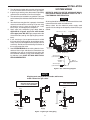
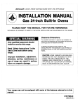
36G22, 36G23, 36G24 & 36G52
36J22, 36J23, 36J24 & 36J52
DSI and HSI Single Stage Combination Gas Valve
INSTALLATION INSTRUCTIONS
Operator: Save these instructions for future use!
FAILURE TO READ AND FOLLOW ALL INSTRUCTIONS CAREFULLY BEFORE
INSTALLING OR OPERATING THIS CONTROL COULD CAUSE PERSONAL INJURY
AND/OR PROPERTY DAMAGE.
DESCRIPTION
The 36G/J22, 36G/J23, 36G/J24 and 36G/J52 combination
gas valves are designed for direct spark ignition (DSI) and
hot surface ignition (HSI) system applications.These valves
are equipped with redundant and main solenoid valves that
control gas flow to the main burners, a pressure regulator
and a two-position on/off switch for regulation and electrical
shut-off of the solenoid valves. The 36G/J23, 36G/J24 and
36G/J52 are also equipped with a slow-opening pressure
regulator for softer lighting characteristics.
36G
36J
SPECIFICATIONS
Type of Gas: Natural gas
LP gas (use conversion kit)
Pressure Regulator Setting:
Nat. Gas – 2.5 to 5.0" W.C.
LP Gas – 7.0 to 12.0"W.C.
Ambient Temperature: -40° to 175°F
Pressure Rating: 14" W.C. (1/2 PSI) max.
Voltage: 24 VAC
Frequency: 50/60 Hz
Current: .360 amps
Mounting Positions:
Multipoise – Control may be mounted in any position.
PIPE SIZES/CAPACITIES
Pipe Sizes
Available
(inches)
1/2" x 1/2" NPT
any combination
Capacity (BTU/hr) at
1” pressure drop across valve
AGA Std. Nat. Gas
LP Gas
(1,000 BTU/cu. ft.) (2,500 BTU/cu. ft.)
140,000
226,800
Parts and Accessories:
CONTENTS
Description ........................................................ 1
Specifications .................................................... 1
Precautions ....................................................... 2
Installation ......................................................... 3
System Wiring
Adjustment ........................................................ 4
Pressure Regulator Adjustment
Lighting Instructions ........................................... 5
Notes ................................................................... 6
F92-0656 - LP to Natural Gas Conversion Kit for use
on Single Stage 36C, D, E, F, G, H, J valves. Regulation
range 2.5" to 5.0" W.C.
F92-0659 - Natural to Regulated LP Gas conversion
Kit for use on Single Stage 36C, D, E, F, G, H, J valves.
Regulation range 7.0" to 12.0" W.C.
F92-1003 - Adapter Kit for the 36G Gas Valves. Kit includes: Connector (5/16" to 1/4" hose barb), tube (5/16"
O.D.) and Hex Wrench (3/32").
PART NO. 37-6159G
www.white-rodgers.com
www.emersonclimate.com
Replaces 37-6159F
1023
PRECAUTIONS
DO NOT BEGIN INSTALLATION UNTIL YOU READ
THE FOLLOWING PRECAUTIONS.
!
WARNING
If you do not follow these instructions exactly, a fire or explosion may
result, causing property damage, personal injury or loss of life.
3. NEVER USE FLAME OR ANY KIND OF SPARK
TO CHECK FOR GAS LEAKS–COULD CAUSE
FIRE AND/OR EXPLOSION.
1. Failure to turn off electric or main gas supply to heating system could cause personal
injury and/or property damage by shock, gas
suffocation, fire, and/or explosion.
4. Do not use a control set for natural gas with
LP gas, or a control set for LP gas with natural
gas. Personal injury and/or property damage,
gas suffocation, fire, and/or explosion may
result.
2. Do not use this control on circuits exceeding
specified voltage. Higher voltage will damage the
control and may cause shock or fire hazard.
!
CAUTION
2. This control is not intended for use in locations
where it may come in direct contact with water.
Suitable protection must be provided to shield
the control from exposure to water (dripping,
spraying, rain, etc.).
1. Do not short out terminals on gas valve or
primary control to test. Short or incorrect wiring can cause equipment damage, property
damage, and/or personal injury.
2
INSTALLATION
1. Turn off electrical power to the system at the fuse box
or circuit breaker. Also turn off the main gas supply.
2. If replacing an existing valve, disconnect all plumbing
and electrical connections from the old control.
3. The control may be installed in any position.The arrow
on the bottom plate indicates the direction of inlet gas
flow.
4. You should use new pipe that is properly chamfered,
reamed, and free of burrs and chips. If you are using
old pipe, be sure it is clean and free of rust, scale,
burrs, chips, and old pipe joint compound.
5. Apply pipe joint compound (pipe dope) that is
approved for all gases, only to the male threads
of the pipe joints. DO NOT apply compound to the
first two threads (see fig. 2 for typical piping connections).
6. If you are using a vise or open-end wrench to hold
the valve while installing piping, do not tighten excessively, as this may damage the valve (Torque: 375 in-lb
maximum). Do not cross-thread during installation as
this may damage the valve.
7. See SYSTEM WIRING when making electrical connections. After all gas and electrical connections are
completed, turn gas on and check for gas leaks with
leak detection solution or soap suds. Bubbles forming indicate a leak. SHUT OFF GAS AND FIX ALL
LEAKS IMMEDIATELY.
SYSTEM WIRING
REFER TO AND FOLLOW THE APPLIANCE MANUFACTURER’S WIRING DIAGRAM. REFER TO FIG. 1
FOR TERMINAL IDENTIFICATION.
NOTE
All wiring should be installed in accordance with local and
national electrical codes and ordinances.
Always check that the electrical power supply used
agrees with the voltage and frequency shown on the gas
control.
Outlet Pressure Boss
Regulator Vent
Regulator
Adjust
Inlet Pressure
Boss (opt.)
Terminals On/Off Switch
24 VAC Input
(.250" terminal)
Electric
“ON/OFF”
Switch
Main &
Redundant
24 VAC Input
(.250" terminal)
Figure 1. Gas valve wiring diagram
NOTE
All piping must comply with local codes, ordinances,
and/or national fuel gas codes.
NOTE: A MANUAL SHUTOFF VALVE
MUST BE INSTALLED WITHIN
6 FEET OF THE EQUIPMENT
NOTE: ALWAYS INCLUDE A
DRIP LEG IN PIPING
Drop
Drop
Horizontal
3 in.
minimum
Piped Gas
Supply
Horizontal
Gas Valve
Riser
Gas Valve
3 in.
minimum
Riser
Piped Gas
Supply
Figure 2. Typical gas valve piping
3
3 in.
minimum
Tubing Gas
Supply
Gas Valve
ADJUSTMENT
Always adjust regulator to provide the correct pressure
according to the original equipment manufacturer's
specifications listed on the appliance rating plate. Replace
regulator cover screw and tighten securely.
PRESSURE REGULATOR
ADJUSTMENT
Controls are shipped from the factory with the regulator
set as specified on the control label. Consult the appliance rating plate to ensure burner manifold pressure is as
specified. If any other outlet pressure is required, follow
instructions below.
Check for Leaks:
Using a leak detection solution or soap suds, check for
leaks at pressure boss screw or pressure tap plug. Bubbles
forming indicate a leak. SHUT OFF GAS AND FIX ALL
LEAKS IMMEDIATELY.
Outlet Pressure Adjustment Range:
Nat Gas 2.5" - 5"
Outlet
Pressure
Regulator
Adjust Tower
LP Gas 7.0" - 12"
Inlet Pressure
Tap Boss
Valve
Inlet
Outlet
Pressure
Regulator
Adjust Tower
NOTE
Valves cannot be adjusted outside these ranges for the
specified gas type.
36G/36J Pressure Testing Ports. (See Figure 3)
Model
Testing and Inlet/Outlet
Pressure Adjustment
Outlet Pressure
Tap Boss
36J22-214
36G24-214/
36J24-214
36G54-214/
36J54-214
5/16" O.D. Pressure Tap
Bosses with 3/32" Hex
Valve
Inlet
1/8” NPT
Inlet
Pressure
Tap
Pressure Tap
Boss Style
Plugged 1/8” NPT
Thread Tap Style
1/8” NPT
Outlet
Pressure
Tap
Figure 3
Pressure port and regulator adjust locations
No need for separate fitting to
check pressure
36G55-214/
36J55-214
36J24-614
36J55-614
Plugged 1/8" NPT Threaded
Pressure Taps
5/16” Hose
Turn off all electrical power to the system to connect
manometer hoses.
Hose on Outlet
Pressure Tap
Boss
For models with PressureTap Bosses, turn the pressure
test screw (3/32" Hex) in the center of the boss not more
than one turn counterclockwise. Attach a 5/16" hose
and manometer over the tapered outlet pressure boss on
the valve (see figure 4). If regulator needs to be adjusted,
please see instructions below. After testing pressure or
adjusting the regulator, turn off all electrical power to the
system, remove manometer hoses, turn outlet test screw
(3/32" Hex) clockwise to seal pressure port. Tighten to 7
in-lb minimum. Turn on system power.
Outlet Pressure
Tap Boss
Figure 4
Hose on pressure tap boss
Regulator
Cover Screw
Plastic
Adjust Screw
For models with 1/8" NPT threaded taps, the outlet
pressure tap plug will need to be removed and a separate
hose fitting installed. If regulator needs to be adjusted,
please see instructions below. After testing pressure or
adjusting the regulator, turn off all electrical power to the
system, remove manometer hoses, remove hose fitting
and re-install plug. Tighten to 60 in-lb max. Turn on system power.
Regulator
Spring
To Adjust Regulator: Energize the valve. Remove regulator cover screw. Turn regulator adjust screw clockwise
) to increase pressure, or counterclockwise
(
(
) to decrease pressure (see fig. 5).
Figure 5
4
LIGHTING INSTRUCTIONS
FOR YOUR SAFETY READ BEFORE OPERATING
!
If you do not follow these instructions exactly, a fire or explosion
may result causing property damage, personal injury or loss of life.
WARNING
• Immediately call your gas supplier from a neighbor’s
phone. Follow the gas supplier’s instructions.
A. This appliance does not have a pilot. It is equipped with an
ignition device which automatically lights the burner. Do not
try to light the burner by hand.
• If you cannot reach your gas supplier, call the fire
department.
B. BEFORE OPERATING smell all around the appliance area
for gas. Be sure to smell next to the floor because some gas
is heavier than air and will settle on the floor.
C. Use only your hand to move the gas control switch. Never
use tools. If the switch will not move by hand, don’t try
to repair it, call a qualified service technician. Force or
attempted repair may result in a fire or explosion.
FOR YOUR SAFETY
“WHAT TO DO IF YOU SMELL GAS”
D. Do not use this appliance if any part has been under
water. Immediately call a qualified service technician to inspect the appliance and to replace any part of the control
system and any gas control which has been under water.
• Do not try to light any appliance.
• Do not touch any electrical switch; do not use any
phone in your building.
OPERATING INSTRUCTIONS
1.
2.
3.
4.
STOP! Read the safety information above on this label.
Set the thermostat to lowest setting.
Turn off all electric power to the appliance.
This appliance is equipped with an ignition device which
automatically lights the burner. Do not try to light the
burner by hand.
5. Remove control access panel.
6. Wait five (5) minutes to clear out any gas. If you then smell
gas, STOP! Follow “B” in the safety information above on
this label. If you don’t smell gas, go to the next step.
7. Push gas control switch to “ON.”
NOTE: Do not force.
8. Replace control access panel.
9. Turn on all electric power to the appliance.
10. Set thermostat to desired setting.
11. If the appliance will not operate, follow the instructions “To
Turn Off Gas To Appliance” and call your service technician
or gas supplier.
TO TURN OFF GAS TO APPLIANCE
1. Set the thermostat to lowest setting.
2. Turn off all electric power to the appliance if service is to
be performed.
3. Remove control access panel.
4. Push gas control switch to “OFF.” Do not force.
5. Replace control access panel.
5
NOTES
6
NOTES
7
White-Rodgers is a division
of Emerson Electric Co.
The Emerson logo is a
trademark and service mark
of Emerson Electric Co.
www.white-rodgers.com
www.emersonclimate.com