1
PUBLICATION
DATE:
PUBLICATION
DATE:05-01-96
05-01-96
REVISION03
REVISION
03
EQUIPMENT
mfg.
mfg.by
WAYNEHOME
HOMEEQUIPMENT
by WAYNE
FETZERCOMPANY
A scon
SCOTT FETZER
COMPANY
FORT
WAYNE,INDIANA
INDIANA
FOBTWAYNE,
AMS-10
AMS.10
TMS-10
TMS.10
Installation
Instructions
Installation
&
& Service
ServiceInstructions
AMS-10/TMS-10
Burner
AMS-1orrMS-10 Power
PowerGas
GasBurner
PART
62693-001
PARTNO.
NO.62693-001
INSTALLATION
INSTRUCTIONS
INSTALLATION
INSTRUCTIONS
These instructions
instructionscover
These
cover the
the installation
installationof
Model
of Model
power gas
gas burner.
AMS-10/TMS-10
AMS-1
OfTMS-1 0 power
burner.Safe
and economical
economical
Safe and
operationof
of the
the burner
its service
life is
operation
burnerthroughout
throughoutits
servicelife
is largely
largely
properinstallation
dependentupon
uponproper
installation
furnace.
dependent
in
in the
the furnace.
gas
Burnersare
Burners
are shipped
from the
the factory
factorywith
with natural
naturalgas
shippedfrom
propanegas
gas orifices
orifices
orificesinstalled,
installed,unless
unlesspropane
orificesare
are specified.
specified.
(See carton
carton markings.)
markings.)See
for location
(See
See below
belowfor
locationof
of alternate
alternate
orifices.
orifices.
B.
B . GAS
PIPING
GAS PIPING
pipingshould
in accordance
Gas
be sized
sizedand
and installed
installedin
accordance
Gas piping
shouldbe
with
with local
localcodes
codesand
and utility
regulations.
utilityregulations.
1.
1.
gas line
gas meter
Run
Runa separate
line from
from the
the gas
meterto
to the
the
separategas
valve installed
installedat
meter.
burner
burnerwith
with a shut
shut off
off valve
at the
the meter.
proper line
Use
line size
size according
accordingto
the charts
charts
Use the
the proper
to the
piping,and
new piping,
locate itit
shown
Alwaysuse
use new
and locate
shownbelow.
below.Always
pipe is
later. Black
Black pipe
is
conveniently
for easy
easy servicing
servicinglater.
convenientlyfor
gas because
practicalfor
for natural
naturalgas
becauseof
of the
the
the
the most
most practical
required;copper
tubingwith
with an
internal
large
largesizes
sizesrequired;
coppertubing
an internal
Pip
recommendedwith
with L.P.
L.P.Gases.
coating
coatingof
of tin
tin is
is recommended
Gases.Pipfrom cutting
ing
ing rnust
must be
clean, free
free from
cutting burrs,
burrs, and
and
be clean,
in structure
The line
line must
must be
be
defects
defectsin
structureor
or threading.
threading.The
gas tight.
durable,
and
durable,substantial,
substantial,
and gas
tight.
2.
2.
Installa tee
f ittingwith
witha sediment
sedimenttrap
trapat
at the
the bottom
bottom
Install
tee fitting
riser to
foreign matter
matter in
in the
the fuel
fuel
of
of the
the riser
to catch
catch any
any foreign
gas valve
line.Install
Installa main
manualgas
valveon
the outside
outside
line.
mainmanual
on the
requiredby
by local
localcodes
of
thefurnace
furnacewhen
whenrequired
codesor
or utility
utility
of the
requirements.
requirements.
3.
3.
gas leaks
for gas
leakswith
with a soapy
soapysolution
solution
Carefully
Carefullycheck
checkfor
brushed
NEVER
NEVERUSE
FLAME.
brushedon
on the
theconnection.
connection.
USEA FLAME.
A.
OF
A. GAS
BURNER
GAS BURNER
BURNERREPLACEMENT
REPLACEMENT
OF OIL
OIL BURNER
1.
1.
CONTENTS
OF
C ON T E N T S
OFCARTON
C A R T ON
Burner
a.
a. Gas
Gas Burner
b.
b. Installation
Installationand
Manual
and Service
ServiceManual
c.
c. Gas
Gas Burner
BurnerGasket
Gasket
2.
2.
BURNER
REMOVING
THE
R EMOV IN G
T H E PRESENT
PR ES EN TBURNER
gas
Before installing
installingthe
Model AMS-1
AMS-'10/TMS-10
Before
OfTMS-1 0 gas
the Model
performing
presentburner
by performing
burner,
burner,remove
removethe
the present
burnerby
the
the following:
following:
powerand
and fuel
fuel supply.
supply"
a.
a. Shut
Shut off
off electric
electricpower
fuel line;
b.
Disconnectand
and remove
removefuel
line; disconnect
disconnect
b. Disconnect
thermostat
thermostatleads
leadsand
and burner
burnercord.
cord.
(3) hexagon
nutsholding
holdingburner
c.
Removethree
hexagonnuts
burner
c. Remove
three(3)
placeand
in
in place
and remove
removeburner.
burner.
Inspectcombustion
replaceifif
d.
d. Inspect
combustionchamber
chamber and
and replace
pipe
furnace and
vent pipe
damaged.
damaged.Also
Also inspect
inspectfurnace
and vent
furnacefor
for corrosion,
loosenedfiton
on top
top of
of the
the furnace
corrosion,loosened
littings,
tings,soot,
soot, etc.
etc.
3.
3.
THE GAS
BURNER
INSTALLING
THE
INSTALLING
GAS BURNER
gasketon
in furnace,
furnace,
Place
Placenew
new burner
burnergasket
on three
three studs
studsin
place with
(3) hexin place
with three
three (3)
mount
burner, fasten
fasten in
hexmount burner,
leadsto
to T.T.
T.T.of
agon
nuts, connect
thermostatleads
of terteragon nuts,
connectthermostat
gaspiping.
piping.
and connect
connectgas
minal
minalboard
boardon
on control
controlbox
boxand
4.
4.
GAS
PIPINGTO
TO FURNACE
FURNACE
GAS PIPING
Pipingand
and Section
SectionC
C Piping
Piping
See
See Section
SectionB
B Gas
Gas Piping
piping.
Charts
about
Chartsfor
for information
information
aboutpiping.
5.
5.
THERMOSTAT
THERMOSTAT
ItIt is
is necessary
necessaryto
heatanticipator
anticipatorsetting
setting
to change
changethe
the heat
gasburner
replacesan
of
of the
thethermostat
thermostatwhen
whenthe
the gas
burnerreplaces
an oil
oil
Failingto
burner.
burner.Reset
Resetthe
to .4
.4 amps.
amps. Failing
to
the anticipator
anticipatorto
make this
in a wide
make
will result
wide temperature
this change
changewill
resultin
temperature
rangein
in the
range
the mobile
mobilehome.
home.
C.
PIPINGCHARTS
CHARTS
c. PIPING
lor Natural
Black
Black Pipe
Pipefor
NaturalGas
Gas
1/2"when
lessthan
20 feet.
feet.
Use
when length
lengthrequired
requiredis
is less
than 20
Use '12"
s/t"
when length
lengthrequired
requiredis
is less
lessthan
feet.
Use
Use 3/
than 60
60 feet.
4 " when
lengthrequired
requiredis
is less
lessthan
100feet.
feet.
Use
1" when
whenlength
than 100
Use 1"
Aluminum or Copper
Copper Tubing
Tubing for Natural
Natural Gas
Gas
Aluminum
th" 0.0.
lessthan
10feet.
Use
feet.
whenlength
lengthrequired
requiredis
is less
than 10
Use'12"
O.D.when
s/a"
requiredis
is less
feet.
Use
whenlength
lengthrequired
lessthan
than 30
30 feet.
4 " 0.0
Use 3/
O.D when
Aluminum
Aluminumor Copper
Tubingfor L.P.
L.P.Gas
Gas
CopperTubing
feet.
lengthrequired
requiredis
is less
lessthan
40 feet.
Use
%" 0.0.
when length
O.D.when
than40
Usels"
3/q"
requiredis
is less
less than
100
when length
Use
lengthrequired
than 100
4 " 0.0.
Use 3/
O.D. when
feet.
feet.
higherthan
roomtemperature
temperature
10.
10. Set
roomthermostat
thermostathigher
than room
Setthe
the room
(centrifugal
so
will start.
start. A safety
safety control
control (centrifugal
so the
the burner
burner will
preventsthe
gas valve
motor)prevents
the gas
valvefrom
from openswitch
in the
the motor)
openswitchin
is supplying
sufficientcombustion
combustion
ing
ing until
the blower
bloweris
supplyingsufficient
until the
air.
air.
INPUT
D.
GAS INPUT
D. CHECKING
NATURALGAS
CHECKINGNATURAL
the burner
burner is
is
Check
label on
the burner
burner to
to be
be sure
sure the
the label
on the
Check the
gas is
is to
used.AlterAlterequipped
whichever gas
withorifices
for whichever
to be
be used.
equippedwith
orificesfor
lnstrucnate
in cloth
cloth bag
attachedto
lo burner.
burner. Instrucnate orifices
orilices are
are in
bag attached
To check
tions
for changing
orifices are
on Page
Page 2.
2. To
check the
the
tions for
changing orifices
are on
the meter
meterfor
for one
revolution
whilethe
the
input,
while
input,time
timethe
the dial
dialon
on the
onerevolution
varies more
more than
50/ofrom
from
burner
is operating.
operating.Iflf the
the time
time varies
than 5%
burner is
gas pressure
pressureaccordthe
the chart,
accordthe times
times shown
shown on
on the
chart,check
check gas
procedurestated
"Pressure
ing
ing to
the procedure
stated on
Page 2 under
to the
on Page
under "Pressure
pressure
pressure reading
Regulator:'
reading matches
matches the
Regulatori' Iflf pressure
the pressure
proper burner
shown
the proper
burner
shown on
on the
the chart,
chart, check
check to
to be
be sure
sure the
problemsshould
gas problems
reis being
Furthergas
be reorifice
orifice is
being used.
used. Further
should be
gas supplier.
gas varies
in BTU
ferred to
local gas
supplier.Natural
Naturalgas
variesin
BTU
ferred
to the
the local
1.050 BTU
foot. The
The chart
chart is
is
value
from 950
value from
950 to
to 1,050
BTU per
oer cubic
cubic foot.
per cubic
based
on an
an average
of 1,000
1,000BTU
BTU per
foot.
based on
averageof
cubic foot.
Btu!
Btu/
I NP UT
INPUT
PRESSURE
PRESSURE
80,000
3. 5' W . C.
80,000 3.5"W.C.
3.5'W.C.
100,000 3.5"W.C.
100,000
TYPE
TYPE
OF
OF
GAS
GAS
THE BURNER
BURNER
H.
ADJUSTINGTHE
H . ADJUSTING
left side
the burner
burnerhousing
housingto
to
1.
Rotatethe
the disc
disc at
at the
the left
side of the
1. Rotate
Rotatethe
air. Rotate
the disc
disc clockwise
clockwiseto
to
adjust
combustionair.
adjustthe
the combustion
increase
combustion air,
air, counter-clockwise
counter-clockwiseto
to dedeincrease c.ombustion
crease
combustionair.
air.
creasecombustion
2.
combustionflame
flame through
through observation
observationdoor
door
2. Observe
Observecombustion
placed in
is placed
immediately
immediatelyafter
after the
the burner
burner is
in operation.
operation.
in color.
color.After
Afterthe
the burner
burnerhas
has
The
The flame
flameshould
shouldbe
be blue
blue in
operated
minutes, flame
flame color
will
operated for
for two
two or
or three
three minutes,
color will
change
changeto
to light
lightorange.
orange.
BURNER
BURNER
ORIFICE
ORIFICE
DIAL
DIAL
SIZE
SIZE
TIME
TIME
PER
PER
REV.
REV.
pulsates or
quietly. Iflf burner
3.
run qUietly.
burner pulsates
or
Burner should
should run
3. Burner
rumbles,
rumbles,rotate
rotatedisc
decreaseair
air supply.
supply.
disc to
to decrease
No.
N o .'19
19
'13
No. 13
No.
11 cu.
ft.
c u . ft.
1 cu.
ft.
cu. ft.
4 5 sec.
45
sec
37
37 sec.
sec
patternand
noiselevel,
level,lock
lockdisc
4.
Afterchecking
flamepattern
and noise
disc
4. After
checkingflame
positionby
Phillipshead
headscrew.
in
in position
by tightening
tighteningPhillips
screw.
Natural
N a tu ra l
Natural
Natural
importantthat
NOTE:
is very
very important
that air
air supply
supply be
be ample
ample
NOTE: Itlt is
An inadequate
without
withoutdecreasing
efficiencyof
of burner.
burner.An
inadequate
decreasingefficiency
(CO).The
monoxide(CO).
amount
The
of air
air can
can cause
cause carbon
carbon monoxide
amountof
products
(COj
carbon
content of
of the
the flue
flue products
carbon dioxide
dioxide (C0
2 ) content
per cent
gas
should
7.0 to
to 8.0
8.0 per
cent for
for natural
naturalgas
shouldapproximate
approximate7.0
per cent
gases.
and
for L.P.
L.P. gases.
and 8.0
8.0 to
to 9.0
9.0 per
cent for
E.
E. CHECKING
L.P. GAS
GAS INPUT
INPUT
CHECKINGL.P.
gas installations
L.P. gas
installationsare
not usually
with meters
meters
L.P.
are not
usuallysuppHed
suppliedwith
gas used.
for
for determining
determiningthe
the amount
amount of
of gas
used.The
The chart
chart shows
shows
per dial
requiredper
revolutionifif a meter
meter is
is used
used that
is
time
time required
dial revolution
that is
cubic feet
feet delivery.
calibrated
for cubic
calibratedfor
deliverv.
Btu!
Bru/
INPUT
INPUT
PRESSURE
PRESSURE
TYPE
t5?t
OF
GAS
GAS
BURNER
BURNER DIAL
D'AL
ORIFICE
SIZE
ORIFICE
SIZE
TIME
T3"t
PER
REV.
REV.
I.
ADJUSTING
ADJUSTINGHEAT
HEATDISTRIBUTION
DISTRIBUTION
"ON"
1.
1. The
The lower
lowerblower
controlshould
should be
be set
set at
at FAN
FAN "ON"
blowercontrol
"OFF" 90.
110: FAN
110?
FAN "OFF"
90.
'l12 sec.
11"W.C- L.P.
Propane No.
80,000
41 1 cu.
80,000 11"W.C.
L.P.Propane
No.41
cu- ft.
ft. 112
sec.
100,000 11"W.C.
11"W.C. L.P.
L.P.Propane
Propane No.
No.36
36 1 cu.
100,000
cu. ft.
ft. 91
91 sec.
sec.
room thermostat
for desired
desiredroom
room temperature.
2.
2. Set
Set room
thermostatfor
temperature.
F.
F. PURGING
PURGINGUNBURNED
UNBURNEDGAS
FROMFURNACE
FURNACE
GAS FROM
heat distribution
3.
Balance the
the heat
distribution by
by adjusting
adjusting register
register
3. Balance
openings.
openings.
'l - Turn
gas valve
"PILOT;' depress
Turn gas
valve control
1.
controlknob
knob to
to "PILOT;'
depressand
and
"OFF:'
turn
turn to
to "OFF:'
J.
room temperature.
2.
2. Set
Set thermostat
thermostatabove
above room
temperature.
FOR SEALED
COMBUSTION
AIR
AIR SUPPLY
SUPPLYFOR
SEALEDCOMBUSTION
1.
1. Replace
Replaceburner
accessdoor
door to
to complete
completethe
the outdoor
outdoor
burner access
passage.
combustion
combustionair
air passage.
powercord.
gas burner
Plug in
in gas
3.
3. Plug
burnerpower
cord.
is enclosed,
homeis
enclosed,be
be sure
vent
2.
the space
spacebelow
belowthe
the home
surea vent
2. Iflf the
or
least18
18square
inchesis
is made
madeto
out
or duct
duct of
of at
at least
squareinches
to free
freeoutfor combustion.
door
door air
air to
to provide
sufficientair
air for
combustion,
Drovidesufficient
gas burner
motorand
4.
4. The
The gas
burnermotor
and blower
blowerwill
willstart,
start,drawing
drawingair
air
gas out
the burner
burner and
forcingunburned
out the
through
through the
and forcing
unburnedgas
the
MU ST RUN
flue.
f lue. BURNER
B URNE RMUST
R U N A MINIMUM
MIN IM U MOF
OF FIVE
FIV E
MINUTESFOR
FORANY
ANY PURGING
MINUTES
PURGINGOPERATION.
OPERATION.
K.
TO PUT
PUT BURNER
BURNEROUT
K. TO
OUT OF
OF OPERATION
OPERATION
THE BURNER
BURNER
G.
G. STARTING
STARTINGTHE
pilotlighter
gasvalve
Turngas
valvecontrol
controlknob
knoband
lightermain
valve
1.
and pilot
mainvalve
1. Turn
"OFFI'
to
to "OFF:'
gas valve
gas
valvecontrol
1. Depress
Depressthe
the gas
1.
controlknob
knob on
on the
the electric
electricgas
"OFFI'
valveand
valve
and turn
turn to
to "OFF:'
room thermostat
2. Set
Set room
thermostatabove
room temperature
2.
aboveroom
temperatureand
and let
let
purge the
gas
run five
five minutes
minutesto
burner
burner run
to purge
the unburned
unburnedgas
from
from the
the furnace.
furnace.
thermostatbelow
below room
room temperature.
temperature.
3.
3. Set
Set thermostat
pilotlighter
"ON:' Depress
lightermain
mainvalve
4.
4. Turn
Turnpilot
valveto
to "ON:'
Depressand
andturn
turn
gas valve
"PILOT:'
knob on
on gas
valveto
control
controlknob
to "PILOT:'
pilot observation
5.
5. Open
Open pilot
observationdoor.
door.
pilotlighter
to pilot
lightertube
6.
Hold match
matchto
tube and
and depress
red button
button
6. Hold
depressred
pilot lighter
lighter valve.
valve. Hold
on pilot
Hold button
on
button down
down 3 seconds
seconds
gas valve.
while depressing
depressingknob
knobon
valve.Hold
while
on gas
Holdcontrol
controlknob
knob
pilot stays
about 60
60 seconds
lightedafter
down
down about
secondsuntil
until pilot
stays lighted
after
releasing
releasingknob.
knob.
pilot- ifif not
7. Observe
Observepilot7.
not lighted
lightedrepeat
repeatsteps
steps 1 through
through6.
6.
pilotobservation
8. Close
Closepilot
8.
door.
observation
door.
"ONl'
gas valve
9. Turn
Turngas
valvecontrol
9
controlknob
knobto
to "ON:'
AMS,t0.'TMS-10
62693-001REV
Al\.lSJ.-rvS-1':"'I £:2593-001
PAGE
FEV 03/05-01-96
03/05-01_96
PAGE22
2.
Turn off
off electric
electricsupply.
supply.
2. Turn
L.
L.
GAS
GAS BURNER
BURNERCONTROLS
CONTROLS
PILOTLIGHTER
1. PILOT
LIGHTERMAIN
MAINVALVE
VALVE
gas to
The Pilot
LighterMain
MainValve
Valvecontrols
controlsthe
flowof
The
PilotLighter
the flow
ot gas
to
pilot lighter
lightervalve.
valve.
the
the pilot
2. COMBINATION
E LE C TR IC GAS
V A LVE AND
C OMB IN A TIONELECTRIC
GA S VALVE
AND
PRESSURE
PRESSUREREGULATOR
REGULATOR
The Combination
Electric Gas
Valve and
The
CombinationElectric
Gas Valve
and Pressure
Pressure
with several
Regulator
Regulatoris
is equipped
equippedwith
severalcomponents.
components.
positions.The
The Gas
ValveControl
Knob has
has three
The
Gas Valve
ControlKnob
three positions.
The
positioncompletely
gas supply.
"OFF" position
completelyshuts
shuts off
off the
the gas
supply.
positionreleases
gas to
"PILOT" position
pilot burner
The
The "PILOT"
releasesgas
to the
the pilot
burner
positionreleases
gas to
pilot
releasesgas
only.
only. The
The "ON" position
to the
the pilot
longas
lighted,and
and to
to the
the main
mainburner
burner
burneras
as long
as itit is
is lighted,
burner
w heniti t is
i s energized
electrically.
when
energi zed
el ectri cal l y.
gas
locatedin
in the
valve,filters
filtersthe
the gas
The
The Pilot
PilotGas
Filter,located
the valve,
Gas Filter,
p i l o tburner.
supply
t o the
th e pilot
b u rn e r.
s upplyto
provides100%
Valveprovides
1000/o
shut-offof
of
safety
The
The Pilot
PilotSafety
SafetyValve
safetyshut-off
pilotis
pilotgas
gas whenever
wheneverthe
is extinguished.
pilot
the pilot
extinguished.
pressurefor
for natural
The
The Pressure
PressureRegulator
Regulatorregulates
regulatespressure
natural
gases.
The
regulator
L.P.
gases.
The
screwdriver
slot
on
and
L.P.
screwdriver
slot
on the
the regulator
and
"NAT:' ifif the
po,intto the
fired
must
the word
word "NAT'
the burner
is to
to be
be fired
must point
burneris
"L.P." ifif itit is
gas.
gasand
with
firedon
L.P.gas.
withnaural
nauralgas
and "L.P."
is to
to be
be fired
on L.P.
pressure,remove
pressuretap
plug
gas pressure,
To check
removethe
tap plug
To
check gas
the pressure
gas valve.
the
combinationelectric
valve. Insert
Insert the
of
of the
the combination
electric gas
pressuretap
the
pressure
fittingof
of the
the manometer
manometerand
connectthe
tap fitting
and connect
rubbertube
from the
fitting to
manometer.Refer
Referto
to
rubber
tube from
the fitting
to the
the manometer.
pressure
manometer instructions
instructions for
lor taking
taking pressure
the
the manometer
pilotburner
readings.
readings.Be
Be sure
the main
mainburner
are
surethe
burnerand
and pilot
burnerare
readings.
both
when making
makingreadings.
both burning,
burning,when
Pressureshould
3.5"W.C.
for natural
natural gas
and
W.C. for
Pressure
should be
be 3.5"
oas and
11.0"
11. 0"W.C.
W . C .for
fo r L.P.
L .P .Gas.
Ga s .
3.
CENTRIFUGALSWITCH
3. CENTRIFUGAL
SWITCH
for the
The
The electric
motor for
the blower
blowerwhich
which supplies
comelectricmotor
suppliescomwitha Centrifugal
bustion
air to
the burner
is equipped
Centrifugal
bustionair
to the
burneris
equippedwith
gas
with the
Switch
wired in
in series
the combination
combinationelectric
electricgas
Switchwired
serieswith
valve.
valve.This
This switch
is normally
normallyopen
open until
until the
the speed
speed of
switch is
the
the blower
blower motor
motor closes
thus opens
opens the
the electric
electric
closes itit and
and thus
gas valve.
valve. The
The valve
valve will
will not
not open
open until
is
gas
until the
the blower
blower is
operating
operatingat
at full
full speed.
speed.
REMOVINGCOMPONENTS
M. REMOVING
M.
COMPONENTS
1.
1. TO
T O REMOVE
RE M O VEBURNER
BU R N ERASSEMBLY
AS SE M BL Y
a.
a. Set
thermostatat lowest
lowest setting.
Set thermostat
setting.
gas supply
meter.
b.
b. Shut
off gas
supplyat
at the
the meter.
Shut off
gas burner
gas supply
c.
burnerelectric
electriccord,
cord,gas
supplyto
to
c. Disconnect
Disconnectgas
leads.
burner,
thermostatleads.
burner,and
and thermostat
hexagon nuts
nuts holding
holding burner
burner in
in
d.
d. Loosen
Loosen three
three hexagon
place. Rotate
10" and
place.
Rotate burner
burner clockwise
clockwise about
about 10°
and
remove
removeburner.
Durner.
TO CHANGE
2.
2. TO
C H A N GEMAIN
MA IN BURNER
B U R N E RORIFICE
OB IFI CE
gas
valve at
meter or
a.
tank.
a. Shut
Shut off
off gas valve
at meter
or storage
storage tank.
pipe union,
power cord,
b.
fuel pipe
b. Disconnect
Disconnectfuel
union, burner
cord,
burner power
plate
aluminum
fittings on
the burner
front plate
aluminumtube
tube fittings
on the
burner front
gas valve.
lead on
and
the gas
and thermocouple
thermocouplelead
on the
valve.
c.
Removetwo
two bolts
the orifice
orifice holder.
holder. Pullout
Pull out
c. Remove
bolts on
on the
holder,and
the holder,
the
and change
changethe
the burner
burnerorifice.
orifice.
procedurefor
Reversethe
for re-assembly.
re-assembly.
d.
the above
d. Reverse
above procedure
purge the
gas line
NOTE:
from the
NOTE: Be
Be sure
to purge
the gas
line
sure to
the air
air from
(See Page
restartingthe
Page 2)
2)
before
the burner.
before restarting
burner. (See
PILOTORIFICE
3.
3. TO
TO CHANGE
CHANGEPILOT
ORIFICEOR
OR THERMOCOUPLE
THERMOCOUPLE
(see steps
holderremoved
removed(see
a.
With orifice
steps a through
through d
a. With
orificeholder
pull out
remove four
four screws,
burner
above)
the burner
above) remove
screws, pull
out the
tube assembly.
tube
assembly.
pilot and
pilot
b.
b. Remove
Removescrews
holding the
the pilot
change pilot
screws holding
and change
orifice
thermocouple.
orifice and/or
and/or thermocouple.
procedure lor
c.
for re-assembly,
Reverse the
above procedure
re-assembly,
c. Reverse
the above
making sure
tight.
making
that all
fittings are
sure that
all the
the tube
tube fittings
are tight.
purge the
gas line
line
NOTE:
the air
from the
the gas
NOTE: Be
Be sure
to purge
sure to
air from
before
restartingthe
before restarting
the burner.
burner.
SERVICE
CHECKS
FURNACES
SERVICE
FORGAS
CHECKSFOR
GAS GUN
GUN FURNACES
A.
Burnerwill
will not
not start
Burner
start when
when thermostat
thermostatcalls
callsfor
for heat
heat
gassupply
1. Be
Be sure
valveis
is turned
1.
suregas
supplyvalve
turnedon
on at
at the
the meter
meterso
so
fuelis
fuel
is being
beingsupplied
to the
the burner.
suppliedto
burner.
gasvalve
2.
k~ob on
2. Be
Besure
valvecontrol
controlkhob
on the
theburner
suregas
burneris
isturned
turned
"oN:'
to
to "ON:'
Be sure
sure the
the electric
electriccurrent
currentis
is on
no
3.
3. Be
on and
and there
thereare
are no
blown
fusesin
in the
furnacecircuit.
blownfuses
the furnace
circuit.
pilotis
4. Be
Be sure
4.
relight
surethe
the pilot
is lighted.
lighted.Iflf extinguished,
relightacacextinguished,
cording
for
cordingto
to Instructions
lnstructions
forStarting
StartingGas
GasBurner,
Burner,Steps
Steps11
(SeeBand
through6.
furtherinstructions
through
6. (See
B andC
C below
belowfor
for further
instructions
pilots.).
on
on pilots.).
it.
12.
12. Iflf burner
motorstill
stilldoes
doesnot
notoperate,
operate,replace
replaceit.
burnermotor
willnot
notlight,
light,check
checkthe
the
13.
13. Iflf burner
burnermotor
motorruns
runsbut
butburner
burnerwill
removing
theend
end
operation
of
switch
the
operation
ofthe
thecentrifugal
centrifugal
switchby
by removing
not enenbell
of the
burnermotor.
motor.Iflf the
the contacts
contactsare
are not
bell of
the burner
closed,
motorhas
has enclosed
enclosedconconclosed.clean
cleanthem.
them.Iflf the
the motor
replacethe
motor.
tacts,
tacts,replace
the motor.
problemsor pilot
pilot outage
B. Pilot
Pilot ignition
ignitionproblems
B.
outagebetween
betweenburner
burner
cycles
cycles
pilotorifice.
1.
1. Check
Checkthe
the pilot
orifice.Iflf dirty,
or replace.
replace.
dirty,clean
cleanor
5. Check
Checkthe
mainburner
5.
the main
orifice. If
or plugged, clean
burnerorifice.
lf dirty
dirtyorplugged,
clean
replaceit.
itit or
or replace
it.
propersize
(See
2.
2. Be
Be sure
sure the
size orifice
is being
used.(See
orificeis
being used.
the proper
"OrificeChart:'
Page1.)
1.)
"Orifice
Chart:'Page
place wires
5. Disconnect
Disconnectwires
wires
6.
wires at
at thermostat
thermostatand
and place
together.
together.Iflf burner
burnerstarts
startsthen
thenthermostat
thermostatis
is defective
defective
and
andshould
shouldbe
be replaced.
replaced.
pilotgas
gasline.
restrictions
3.
in
3. Check
Checkfor
for restrictions
in the
the pilot
line.Blowout
Blowoutthe
the
pilotline.
pilot
line.
7. Check
lighttester
7.
Checkthe
thecontrol
controlcircuit
circuitwith
withaa light
testeror
volt-ohm
or volt-ohm
meterfor
for loose
looseconnections
meter
or
wires.
connections
or broken
brokenwires.
gas
the current
8. Check
Checkthe
currentto
to the
the combination
8.
combinationelectric
electricgas
valve.Iflf circuit
valve.
circuitis
is closed
closed.a'nd
vatvedoes
ihO valve
does not
not open,
open,
replacevalve.
replace
valve.
pressureregulator.
9. Check
the pressure
regulator.Iflf regulator
9.
Checkthe
regulatorwill
not adwill not
adjust
hold to
gas
and hold
to 3112"
just and
31/2"Water
WalerColumn
for natural
naturalgas
Columnfor
(L.P.gases
gasesare
operation,
replaceregulator.
regulator.
operation,
replace
(L.P.
regulated
areregulated
at
at the
thetank.
tank.Be
Besure
regulatoron
on the
theburner
is open
lor
sureregulator
burneris
openfor
gasoperation.)
L.P.
L.P.gas
operation.)
gasline.
gasline
4. Be
4.
Besure
surethere
thereis
isno
noair
airin
inthe
thegas
line.Purge
Purgethe
thegas
line
instructionson
Page2.
according
accordingto
to the
the instructions
on Page
2.
pressure.Iflf too
gaspressure.
highor
low,check
with
5.
5. Check
Checkgas
too high
or too
too low,
checkwith
gaspilot
pilotpressure
pressurenormally
(Nat.gas
thefuel
fuelsupplier.
normallyis
is7"
the
(Nat.
supplier.
pressurenormally
gaspilot
pilotpressure
WaterColumn;
Water
Column;L.P.
L.P.gas
normallyis
is 11"
11"
WaterColumn.)
Water
Column.)
gas valve
6.
6. Be
Be sure
sure the
the connection
connectionbetween
betweenthe
valve and
and
the gas
thermocoupleis
is tight
thermocouple
tight to
to ensure
ensurecontact.
contact.
10. Check
tor 24
10.
transformerfor
24 volt
volt output.
no
Checkburner
burnertransformer
output.Iflf no
voltage,replace
replacetransformer.
voltage,
transtormer.
7. Check
with millivoltmeter.
7.
Check thermocouple
thermocouplewith
millivoltmeter. Voltage
Voltage
no less
lessthan
than88 millivolts
millivoltsclosed
should
shouldbe
be no
closedcircuit
circuitand
and
from18
18to
millivolts
open
range
rangefrom
to 32
32 millivolts
opencircuit.
A reading
readingof
circuil.A
of
lessthan
18millivolts
millivoltsindicates
indicatesaa weak
less
than18
weakthermocouple
thermocouple
replaced.
be replaced.
and
and itit should
shouldbe
11. Check
check the
relayoutput.
output.Iflf less
lessthan
11.
the burner
burnerrelay
than 110
110volts,
volts,
replacerelay.
replace
relay.
pilotoutage.
(See
8.
combustion
air
8. Excessive
Excessive
combustion
aircan
cancause
causepilot
outage.(See
Adjustingthe
Page
Page22 Adjusting
the Burner.)
Bumer.)
AMS-10/TM910 62693-001
PAGE 3
AMs-l0rrMS-l0
62693-001 REV.
REV. 03105-01-96
03/05{1-96 PAGE
palotis
Burner motor
c. Burner
motor runs,
runs, pilot
is lighted,
lighted, but
but no
no burner
burner flame
llame
C.
gas
1.
Be
sure
valve
control
knob
on
the
is
burner
turned
1. Be sure gas valve control knob on the burner is turned
" O Nl'
t o "ON:'
to
gas pressure
pressureand
2. Check
Check gas
and thermocouple
thermocoupleas
as outlined
outlinedin
in
2.
B
5.
6and7ab
ove.
B-5, 6 and 7 above.
3. Check
gas valve
Check combination
combinationelectric
electricgas
valve as
as outlined
outlinedin
in
3.
A-6 above.
above.
A-6
4. Check
Check the
the contacts
contacts of
of the
the centrifugal
centrifugalswitch
switch as
as outout4.
linedunder
underA-12
A-12above.
above.
lined
D. Burner
Burner flame
flame without motor
motor running
running
D.
Dirt on
on the
the valve
valve seat,
seat, or
gas
or an
an obstruction
obstructionin
in the
the main
main gas
Dirt
permittinggas
valve is
gas to
is permitting
leak to
to leak
to the
the burner.
burner.Replace
Replacecomcomvalve
gas valve.
binationelectric
electricgas
valve.
bination
E. Intermittent
Intermittent burner
burner operation
operation
E.
1. Be
room thermostat
Be sure
sure room
thermostat is
is not
not located
located near
near another
another
1.
heat or
or cold
coldsource,
source,i.e.,
i.e.,lamps,
lamps,kitchen
kitchenrange,
range,over
overaa
heat
register,in
in sunlight,
sunlight,near
nearan
an outside
outsidedoor,
door,etc.
etc.
register,
2. Be
Be sure
sure the
the return-air
return-airfilter
filter is
is clean.
clean.
2.
3. Be
Be sure
sure the
the lower
lower blower
blower switch
switch setting
is at
seiling is
at 85°
85o or
or
3.
below.
below.
F. Noisy
Noisyfire
fire
F.
Re-adjust
combustion
discto
to reduce
reducethe
thevolume
volumeof
airdisc
of air
air
Re-adjust
combustion
air
(SeePage
drawninto
intothe
theburner.
Page2.)
2.)
beingdrawn
burner.
being
(See
gasbills
Highgas
bills
G. High
G.
Checkcombustion
combustion
adjustment.
airadjustment.
1'l Check
air
propersize
(See"Orifice
"Orifice
Besure
2. Be
sureproper
sizeorifice
orificeisisbeing
beingused.
used.(See
2.
Page1.)
1.)
Chartl'Page
Chart;'
Besure
return-air
filterisisclean.
3. Be
surereturn-air
clean.
3.
filter
4. Be
Besure
homeisisinsulated,
insulated,
windows
anddoor
fittightly,
surehome
doorfit
tightly,
4.
windows
and
no air
leaksin
in the
heatingducts.
andthere
thereare
areno
air leaks
the heating
ducts.
and
roomthermostat
to be
5. Check
Checkroom
thermostatto
be sure
surethe
the setting
settingis
is not
not
5.
higherthan
necessary.Low
Low humidity
humidityrequires
requireshigh
than necessary.
high
higher
temperatures
lor comfort.
comfort.Perhaps
Perhapshumidity
humidityshould
shouldbe
be
temperatures
for
increased.
increased.
H . Circulation
will not
Girculationblower
blower will
not operate,
operate,even
even though
though the
the
H.
burneroperates
operates
burner
1. Check
Checkupper
upperblower
blowerand
and burner
burnerswitch
switchand
and lower
lower
1.
blowerswitch.
switch.
blower
2. Check
theelectrical
Checkthe
electrical
connections
to the
theblower
motor.
blowermotor.
2.
connections
to
outthe
3. Check
Checkout
the blower
blowermotor.
motor.
3.
4. Check
Check the
the control
(See A-5
control circuit.
circuit. (See
A-5 above.)
above.)
4.
5. Check
Check the
the thermocouple.
(See B-6
thermocouple.(See
8-6 and
and 7 above.)
above.)
5.
AMS-IO
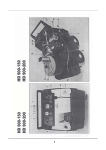
GA S BURNER
W IR IN G
B U R N E R WIRING
GAS
T hllrmoslal
Gas Valve
BK
24 V T r o n s
Trmc Dcloy Rcloy
AMS-10/TMS-10
AMS-l0fTMS·10 62693-001
62693-001 REV.
REV. 0305-01-96
03105-01·96 PAGE
PAGE 44
BK
REF.
REF.
NO.
NO .
1I
2
2
3
4
PART
NO.
PARTNO.
DESCRIPTION
DESCRIPTION
60151
ro.t:''
..
60154
60,1.54
*•
60155
601
55
61455
61455
61428
61428
60160
60160
60161
601
61
61407
61407
60359
60359
61637
61637
60171
60171
14
14
15
15
60172
60172
60353
603s3
PART NO.
PART
NO.
16
16
17
17
18
18
19
19
20
20
21
21
22
22
23
23
24
24
24
24
25
25
26
26
27
27
601n
60177
60178
60178
100018
100018
60356
60356
60186
60186
61444
61444
't2946
12946
62503-021
62503021
60192
60192
60193
60193
60194
60194
60198
60198
60728
60728
29
29
30
30
31
31
32
32
'33
*33
60239
60239
61430
614it0
60196
60196
60196
60196
60006
60006
Pipe Union
Pipe
Union
Nipple
Off Set Nipple
Valve
Gas Valve
Gas
Elbow
Elbow
**
60150
60150
6
7
8
9
10
10
10
10
10
10
10
10
11
1' 1
12
12
13
13
REF.
REF.
NO.
NO.
Thermocouple
Thermocouple
Elbow
Elbow
Orifice Holder
Holder
Orifice
Bulkhead
Union
Bulkhead Union
'100
Orifice
Orifice - Nat.
Nat. 100
Orilice- Nat.
Nat. 80
80
Orifice
LP 80
80
Orifice
Orifice- LP
100
Orifice
LP 100
Orifice - LP
Coverplate
Coverplate
Mixer Tube
Tube
Mixer
Fasco
Centrifugal
Centrifugal Switch
Switch Fasco
Micro Switch
SwitchFranklin
Micro
Franklin
Blower,Motor
Motor&
& Wheel
Wheel
Blower,
Air Shutter
Shutter
Air
ControlBox
Control
Box
TerminalBoard
Terminal
Board
Power
Power Cord
Cord
Control Cover
Control
Cover
Transformer
Transformer
Relay
Relay
Burner
Gasket
Burner Gasket
Housing
Burner Housing
Burner
Pilot
Pilot Orifice
Orifice - Nat.
Nat.
Pilot
Orifice - LP
LP
Pilot Orifice
Pilot
Pilot
Pilot
Shield
Pilot Shield
Pilot
Tube
Pilot Tube
Pilot
Tube
Pilot Lighter
Lighter Tube
Pilot
Pilot Valve
Valve
Lighter Tube
Lighter
Tube
Feeder
Tube
Feeder Tube
Valve
Shut-Off
Shut-Off Valve
purchasedat
local hardware
hardwarestore.
store.
be purchased
at local
*-'May
• May be
'Not Shown
*Not
Shown
\
DESCRIPTION
DESCRIPTION
p
15
13'-'
1./
l?
-.-
?'i
4
Q28'\
4
1.
30
Tz
\\--A
1..
--.-Y
i \o^
6;"
t-I
31
AMS-10/TMS-1062693-001
62693{01 REV.
REV.03/05-01-96
PAGE5
03/05{1-96 PAGE
AMS·l0rrMS·10
The
The
Burner
BurnerModel
ModelNo.
No.
----,:-:-;---:(Make)
(Make)
i nsta lledat
at
installed
,, Serial
No.
Serial No.
_
Bears
1978
B earsa label
l abelevidencing
w i th ANSZ21.17b
A N S Z21.17b
197 8and
has
evi denci ngcompliance
compl i ancewith
and has
,...,--,,...,.---_---;-;-----:---::---:-;--,--(Addressof Installation)
(Address
Installation)
beeninstalled
installed
in accordance
accordance
with the
the instructions
instructions
in the
the manufacturer's
been
in
with
in
installation
manual
with
manufacturer's
installation
manualand
in conformity
conformity
withlocal
local
andin
regulations,
ordinances.
regulations,
codes,
codes,and
and ordinances.
No. ,and
No.
the Input
lnput
, andthe
The
The Furnace
Furnace
(Make)
(Make)
of
of unit
unit consists
consistsof
of
BTUH
BTUH
CO
CO, In
l n Flue
F lue
o
%
Flue
Flue Gas
Gas Temperature
Temperature
OF
oF
CO
In Flue
F lue
CO In
%
%
Ambient
AmbientTemperature
Temperature
OF
of
Net
Net Flue
FlueGas
Gas Temperature
Temperature
OF
oF
2
Overfire
Overfire
Draft
DraftIn
In Flue
Flue
_
(inchesH
(inches
0)
HrO)
2
Firing
Fi ri ngRate
B ate
BTU/HR
BTU/HR
properinstallation
lim it i n gdevices
h a v ebeen
All
Al l controls
co nt r olsand
and limiting
d e v i c e shave
b e e nchecked
c h e c k e dfor
for proper
i nstal l ati on
Gas
Gas
Fuel
Fuel used,
us ed,
"w.c.
"W.C.
Manifold
ManifoldPressure
Pressure
_
Gas
Pressure
GasSupply
SupplyPressure
Inches
l nchesW.C.
W. C.
The above
test results
results are
are certified
certified to be
true: - - - - - - - - : - ; - ; - - - - ; - ; : : - - - - - - ; - - ; - : - - - - - - : - ; - - - : - ; - ; - - : - 7 . , . - , - - - - - - - - - - - - above test
be true:
The
Per
Per
--:=_-,----,--( Sig n a tu r e )
(Signature)
(N ameof
(Name
of Company
Maki ngInstallation)
Instal l ati on)
C ompanyMaking
Address:
Address:
Phone:
Phone:
_
FOR
FOR SERVICE
SE RV I CECALL:
CA LL:
Name:
Name :
Phone:
P hone:
Address:
Address:
Date:
Date:
_
_
!-WAYNE\
,
I
WAYNEHOME
HOT'EEQUIPMENT
WAYNE
EOUIPMENT
A SCOTT
SCOTT FETZER
FETZERCOMPANY
COMPANY
801 Glasgow
801
GlasgowAvenue
Avenue
Forl Wayne.
Wayne, Indiana
Indiana 46803
46803
Fort
LIMITEDWARRANTY
LIMITED
WARRANTY
products and
(Wayne)warrants
faulty workmanworkmanWayne
f rom defects
defects due
due to faulty
Home Equipment
warrantsits
its products
and components
f ree from
Wayne Home
Equipment(Wayne)
componentsto be
be free
(' t2)months
monthsfrom
from the
the date
d at e of
of ininship
m at e ri a l sat
ti m e of
o f shipment
a n d under
u ndernormal
normaluse
for twelve
tw el ve(12)
sh i p or
or defective
def ec t iv emate~ials
a t time
s h i p me n tand
use and
and service
servi cefor
qualifie d installer
(1 8 )months
f ir st .This
This
months from
date occurs
occursfirst.
stallation
i n s ta l l e ror
o r eighteen
e i g h te e n(18)
f rom the
the date
manufacture,which
w hi ch ever
everdate
sta l l at ionby
by a qualified
date of
of manufacture,
products,or
has been
m isused,
n o t extend
o r apply
W ayne' sproducts,
w hi ch has
beenmisused,
LIMITED
L IMITE DWARRANTY
W A RRA NT Ydoes
d o e s not
e x te n dor
a p p l y to Wayne's
thereof,which
or any
any component
componentthereof,
w orkmanshi pand
which is
is
neglected,
n egl e c t ed,improperly
im pr oper l yinstalled
i n s ta l l e dor
o r otherwise
o th e rw i s eabused.
a b u s e d .Equipment
E qui pmentwhich
materi alor
or workmanship
and which
w hi ch is
i s defective
defecti vein
i n material
p e ri o dwill
re p ai redor
removed
re mo v edwithin
t he specific
ti m e period
w i l l be
b e repaired
or replaced
repl acedas
wit hin the
s p e c i fi ctime
as follows:
fol l ow s:
poi nt or
(1 ) Field
or distributor
di stri butorof
of Wayne
Wayne
(1)
Fi eld units,
c ont r o l s ,motors
mo to rs &
tra n s fo rm e rsshould
s h oul dbe
be returned
returnedto
to an
servi cepoint
unit s ,controls,
& transformers
an authorized
authori zedservice
point or
sai d service
or
for
o f this
th i s LIMITED
w heresaid
servi cepoint
for determination
o f applicability
a p p l i c a b i l i tyof
L IM IT EDWARRANTY
W A R R A N TYas
as to
to repair
repai ror
or replacement
repl acementwhere
det er m inat ionof
is reasonably
r eas o n a b l yavailable
l ocal i ty.
distributor
a v a i l a b l ein
i n customer's
c u s to m e r ' slocality.
d i s t r ibut oris
(2) Where
transformers,or
or where
where
not avialable
(2)
motors &
& transformers,
local service
is not
avialablefor
lor components
components involving
involvingsaid
controls, motors
Where such
such local
service is
said controls,
products should
prepaid,to Wayne's
home office.
off ice.
other
involved,such
such products
returned,freight
Wayne's home
other components
are involved,
should be
be returned,
freight prepaid,
componentsare
or replaced
replacedat
(3) Products
this LIMITED
repairedor
at
(3)
Productsdetermined
be covered
coveredunder
under this
LIMITEDWARRANTY
WARRANTYby
be either
either repaired
determinedto be
by Wayne
Wayne shall
shall be
opt i o n .
Wayne's
Way ne' ssole
s ole option.
productsand
(4) Wayne
for any
labor cost
for removal
removaland
(4)
responsiblefor
any labor
cost for
and equipment
equipmentassociated
associated
replacementof
of said
Wayne is
is rlot
not responsible
and replacement
said products
therewith.
th er ewit h.
other components
this LIMITED
LIMITEDWAR·
WAR(5) Controls,
(5)
transformers,or
or other
componentswhich
replacedwill
will carry
carry this
motois &
& transformers,
which are
repairedor
or replaced
Controls,motois
are so
so repaired
portion of
product LIMITED
of the
the original
original product
RANTY
the unexpired
unexpiredportion
RANTYequal
equal to the
LIMITEDWARRANTY.
WARRANTY.
productwill
(6) If
not disclose
repaired
discloseany
will be
be repaired
(6)
lf inspection
inspectionby
Waynedoes
does not
any defect
defect covered
coveredby
by Wayne
by this
this LIMITED
LIMITEDWARRANTY,
WARRANTY,the product
o f the
th e customer
t he expense
c u s to m e rand
a n d Wayne's
W ayne' sregular
regul archarges
or
o r replaced
r eplac edat
at the
e x p e n s eof
w i l l apply.
appl y.
chargeswill
T H E SOLE
S OL EAND
A N D EXCLUSIVE
OR FOR
FORA
N Y OTHER
O THER
THE
STATES
REMEDY
ANY
THE FOREGOING
FO RE G O I NG
EX C L U SIV E
R E ME D YFOR
FORANY
W A R R A N TYOR
S T A T E STHE
A N Y BREACH
B R E A C HOF
OF WARRANTY
IN , OR
S OU N D IN GIN
I N CONCO N.
CLAIM
ANY
N Y DEFECT
D E F EC TIN,
OR NON·PERFORMANCE
N ON -P ER FOR MA N COF,
E THE
W
C LAIM BASED
B A S E D ON
ON A
OF,
TH E PRODUCTS,
P R OD U C TSWHETHER
, H E TH E RSOUNDING
IN
ANY
N O OTHER
OR
IMP LIE DINCLUDING
, C LU DI NGANY
TRACT,
NO
N EGL IGE N C E.
OT H E RWARRANTY,
W A R R A N TYWHETHER
W
, H E TH E REXPRESSED
TR AC T ,WARRANTY
W A RRA NT YOR
O R NEGLIGENCE.
E X P R E S S E OR
D IMPLIED,
WI TH
OR
F IT N ES SFOR
IN CONNECTION
C ON N E C TI O N
WARRANTY
PURPOSE,
WITH
M E RC H A N T A BIL ITOR
Y FITNESS
FOR A PARTICULAR
P A R TIC U LA R
E X IS TIN
WARRA NT YOF
O F MERCHANTABILITY
P U R P OS ESHALL
S, H A LLEXIST
A N D IN
OR CONSECO NSE.
TH E SALE
PR OD U C T S
IN NO
FORANY
IN C ID E N TA OR
L
THE
AND
SALEOR
O R USE
US EOF
O F SUCH
S U C HPRODUCTS
N O EVENT
E V E N TWILL
A N Y INCIDENTAL
W ILLWAYNE
W A Y N EBE
B E LIABLE
LIA B LEFOR
ot her
personto
f or Wayne
W ayneany
anyother
W
n e i therassumes
QUENTIAL
to assume
assumefor
DA M A G E SOF
A N Y NATURE.
N AT U R EWayne
. a y n eneither
assumesnor
nor authorizes
QUEN T I A LDAMAGES
OF ANY
authori zesany
any person
th e sale
products.
w i th the
s a l e of
o f these
liability
l i a bi l i tyor
or obligation
obligat ionin
i n connection
c o n n e c ti o nwith
these products.
AMS-1o/TMS-10 62€rO-OC1
AMS-l0/TMS-l0
ii?693-0o1 RE:V
REV 03;05-01-96
PAGE 6
03/05-0r 96 PAGE