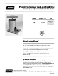
1
Owner's Manual and Instructions
GreenGro Plus™ Greenhouse Heaters
MODELS
OUTPUT (Btuh)
HD120
120,000
FUEL
Available in either
L.P. Gas Vapor
Withdrawal or
Natural Gas
Configurations.
Congratulations!
You have purchased the finest direct fired greenhouse heater available.
Your new L.B. White heater incorporates the benefits from the most experienced
manufacturer of heating products using state-of-the-art technology.
We, at L.B. White, thank you for your confidence in our products and
welcome any suggestions or comments you may have...call us, toll-free,
at 1-800-345-7200.
ATTENTION ALL USERS
This heater has been tested and evaluated by C.S.A. International, in accordance
with IAS U.S. Requirements for Gas-Fired Greenhouse Heaters, for use as a direct
gas-fired circulating heater for the heating of greenhouses. If you are considering
using this product for any application other than its intended use, then please
contact your fuel gas supplier, or the L.B. White Co., Inc.
150-23487-A
GENERAL HAZARD WARNING
■ Failure to comply with the precautions and instructions provided with this heater, can result in:
— Death
— Serious bodily injury or burns
— Property damage or loss from fire or explosion
— Asphyxiation due to lack of adequate air supply or carbon monoxide poisoning
— Electrical shock
■ Read this Owner’s Manual before installing or using this heater.
■ Only properly-trained service people should repair or install this heater.
■ Save this Owner’s Manual for future use and reference.
■ Owner’s Manuals and replacement labels are available at no charge. For assistance, contact
L.B. White at 800-345-7200.
WARNING
■ Proper gas supply pressure must be provided to the inlet of the heater.
■ Refer to dataplate for proper gas supply pressure.
■ Gas pressure in excess of the maximum inlet pressure specified at the heater inlet can cause
fires or explosions.
■ Fires or explosions can lead to serious injury, death, building damage, or plant loss.
■ Gas pressure below the minimum inlet pressure specified at the heater inlet may cause
improper combustion.
■ Improper combustion can lead to asphyxiation or carbon monoxide poisoning and therefore
serious injury or death to humans and plant life.
WARNING
Fire and Explosion Hazard
WARNING
Fire and Explosion Hazard
■ Keep solid combustibles a safe distance
away from the heater.
■ Not for home or recreational vehicle use.
■ Solid combustibles include wood or paper
products, straw, and dust.
■ Installation of this heater in a home or
recreational vehicle may result in a fire or
explosion.
■ Do not use the heater in spaces which
contain or may contain volatile or airborne
combustibles.
■ Volatile or airborne combustibles include
gasoline, solvents, paint thinner, dust
particles or unknown chemicals.
■ Failure to follow these instructions may
result in a fire or explosion.
■ Fire or explosions can lead to property
damage, personal injury or loss of life.
■ Fire or explosions can cause property
damage or loss of life.
FOR YOUR SAFETY
Do not store or use gasoline or other
flammable vapors and liquids in the vicinity of
this or any other appliance.
FOR YOUR SAFETY
If you smell gas:
1. Open windows.
2. Don't touch electrical switches.
3. Extinguish any open flame.
4. Immediately call your gas supplier.
2
Table of Contents
SECTION
PAGE
General Information . . . . . . . . . . . . . . . . . . . . . . . . . . . . . . . . . . . . . . . . . . . . . . . . . . . . . . . . . . . . . . . . . . .3
Heater Specifications . . . . . . . . . . . . . . . . . . . . . . . . . . . . . . . . . . . . . . . . . . . . . . . . . . . . . . . . . . . . . . . . . .4
Safety Precautions . . . . . . . . . . . . . . . . . . . . . . . . . . . . . . . . . . . . . . . . . . . . . . . . . . . . . . . . . . . . . . . . . . . .5
Installation Instructions
General . . . . . . . . . . . . . . . . . . . . . . . . . . . . . . . . . . . . . . . . . . . . . . . . . . . . . . . . . . . . . . . . . . . . . . . . .7
Air Diverter Installation Instructions . . . . . . . . . . . . . . . . . . . . . . . . . . . . . . . . . . . . . . . . . . . . . . . . . .8
Indoor Installation Instructions . . . . . . . . . . . . . . . . . . . . . . . . . . . . . . . . . . . . . . . . . . . . . . . . . . . . . .9
Sediment Trap Assembly Instructions . . . . . . . . . . . . . . . . . . . . . . . . . . . . . . . . . . . . . . . . . . . . . . . .10
Heater Control Instructions . . . . . . . . . . . . . . . . . . . . . . . . . . . . . . . . . . . . . . . . . . . . . . . . . . . . . . . .10
Manual Shut-Off Valve, Hose and Regulator Assembly Instructions . . . . . . . . . . . . . . . . . . . . . . . .12
Start-Up Instructions . . . . . . . . . . . . . . . . . . . . . . . . . . . . . . . . . . . . . . . . . . . . . . . . . . . . . . . . . . . . . . . . .13
Shut-Down Instructions . . . . . . . . . . . . . . . . . . . . . . . . . . . . . . . . . . . . . . . . . . . . . . . . . . . . . . . . . . . . . . .13
Cleaning Instructions . . . . . . . . . . . . . . . . . . . . . . . . . . . . . . . . . . . . . . . . . . . . . . . . . . . . . . . . . . . . . . . . .14
Maintenance Instructions . . . . . . . . . . . . . . . . . . . . . . . . . . . . . . . . . . . . . . . . . . . . . . . . . . . . . . . . . . . . .14
Service Instructions
General . . . . . . . . . . . . . . . . . . . . . . . . . . . . . . . . . . . . . . . . . . . . . . . . . . . . . . . . . . . . . . . . . . . . . . . .15
Motor & Fan Assembly . . . . . . . . . . . . . . . . . . . . . . . . . . . . . . . . . . . . . . . . . . . . . . . . . . . . . . . . . . . .15
Air Proving Switch . . . . . . . . . . . . . . . . . . . . . . . . . . . . . . . . . . . . . . . . . . . . . . . . . . . . . . . . . . . . . . . .15
Flapper Adjustment . . . . . . . . . . . . . . . . . . . . . . . . . . . . . . . . . . . . . . . . . . . . . . . . . . . . . . . . . . . . . . .16
Igniter & Flame Sensor . . . . . . . . . . . . . . . . . . . . . . . . . . . . . . . . . . . . . . . . . . . . . . . . . . . . . . . . . . . .16
Removing Control Box and Wire Harness . . . . . . . . . . . . . . . . . . . . . . . . . . . . . . . . . . . . . . . . . . . . .17
Testing the Manual Reset High Limit Switch . . . . . . . . . . . . . . . . . . . . . . . . . . . . . . . . . . . . . . . . . . .17
Gas Pressure Checks . . . . . . . . . . . . . . . . . . . . . . . . . . . . . . . . . . . . . . . . . . . . . . . . . . . . . . . . . . . . .18
Troubleshooting Instructions . . . . . . . . . . . . . . . . . . . . . . . . . . . . . . . . . . . . . . . . . . . . . . . . . . . . . . . . . . .19
Electrical Connection and Ladder Diagram . . . . . . . . . . . . . . . . . . . . . . . . . . . . . . . . . . . . . . . . . . . . . . .25
Heater Component Function . . . . . . . . . . . . . . . . . . . . . . . . . . . . . . . . . . . . . . . . . . . . . . . . . . . . . . . . . . .26
Parts Identification (Parts List & Schematic) . . . . . . . . . . . . . . . . . . . . . . . . . . . . . . . . . . . . . . . . .27 & 28
Warranty Policy . . . . . . . . . . . . . . . . . . . . . . . . . . . . . . . . . . . . . . . . . . . . . . . . . . . . . . . . . . . . . . . . . . . . .29
Replacement Parts and Service . . . . . . . . . . . . . . . . . . . . . . . . . . . . . . . . . . . . . . . . . . . . . . . . . . . . . . . .29
General Information
This Owner's Manual includes all options and accessories
commonly used on this heater. However, depending on the
configuration purchased, some options and accessories
may not be included.
When calling for technical service assistance, or for other
specific information, always have model number,
configuration number and serial number available. This
information is contained on the dataplate.
This manual will instruct you in the operation and care of
your unit. Have your qualified installer review this manual
with you so that you fully understand the heater and how it
functions.
3
The gas supply line installation, installation of the heater,
and repair and servicing of the heater requires continuing
expert training and knowledge of gas heaters and should
not be attempted by anyone who is not so qualified. See
page 6 for definition of the necessary qualifications.
Contact your local L.B. White distributor or the L.B. White
Co., Inc. for assistance, or if you have any questions about
the use of the equipment or its application.
The L.B. White Co., Inc. has a policy of continuous product
improvement. It reserves the right to change specifications
and design without notice.
Heater Specifications
Model
HD120
SPECIFICATIONS
Propane
Gas
Natural
Gas
Maximum Input (BTUH)
Minimum Input (BTUH)
120,000
65,000
EXHAUST FAN
Indoor Mounting Air
Exchange Requirements (1) SHUTTERED AIR INLET
300 CFM
120 sq. in.
Outdoor Mounting Air
SHUTTERED
Exchange Requirements (1) EXHAUST OUTLET
Inlet Gas Supply
Pressure Acceptable at
the Inlet of the Heater
for Purpose of Input
Adjustment (In. W.C.)
Burner Manifold
Pressure (In. W.C.)
Fuel Consumption Per
Hour
120 sq. in.
MAX.
13.5
11.0
MIN.
11.0
7.0
MAX.
5.2
3.1
MIN.
1.3
0.8
MAX.
5.56 lbs.
120 cu. ft.
MIN.
3.01 lbs.
65 cu. ft.
Ball Bearing
Motor Characteristics
1/3 H.P.
1,100 RPM
Electrical Supply
(Volts/Hz/Phase)
115/60/1
Amp Draw
STARTING
11.8
CONTINUOUS
OPERATION
4.5
Dimensions (Inches)
LxWxH
Minimum Safe
Distances From
Nearest
Combustible
Materials
Net Weight (lbs.)
Shipping Weight (lbs.)
30 3/4 x 18 1/4 x 28 1/4
TOP
SIDES
BACK
BLOWER
OUTLET
GAS
SUPPLY
1 ft.
1 ft.
1 ft.
6 ft. (1.83 m)
Propane Gas Supply — 6 ft. (1.83 m)
Natural Gas Supply — N/A
116
126
(1) Air inlets and exhaust outlets must be electromechanically operated and electrically interlocked with the heater to
prevent heater operation if air inlet and exhaust outlet do not open when heating is required.
4
Safety Precautions
WARNING
■
■
■
■
Asphyxiation Hazard
Do not use this heater for heating human living ■ Refer to the specification section and installation
quarters.
instructions of the heater’s Owner’s Manual, heater
dataplate, or contact the L.B. White Company to
Do not use in areas without proper air exchange. See
determine air exchange requirements of the heater.
air exchange requirements on page 4 or on heater’s
dataplate.
■ Lack of proper air exchange will lead to improper
combustion.
Exhaust fans, supply air inlets, or exhaust fan outlets
must not be obstructed.
■ Improper combustion can lead to carbon monoxide
poisoning in humans leading to serious injury or death.
Proper air exchange must be provided for either indoor
Symptoms of carbon monoxide poisoning can include
or outdoor mount installations.
headaches, dizziness and difficulty in breathing.
FUEL GAS ODOR
LP gas and natural gas have man-m
made odorants added specifically for detection of fuel gas leaks.
If a gas leak occurs, you should be able to smell the fuel gas.
THAT’S YOUR SIGNAL TO GO INTO IMMEDIATE ACTION!
■ Do not take any action that could ignite the fuel gas. Do
not operate any electrical switches. Do not pull any
power supply or extension cords. Do not light matches
or any other source of flame. Do not use your
telephone.
■ Get everyone out of the building and away from the area
immediately.
■ Close all propane (LP) gas tank or cylinder fuel supply
valves, or the main fuel supply valve located at the
meter if you use natural gas.
■ Propane (LP) gas is heavier than air and may settle in
low areas. When you have reason to suspect a propane
leak, keep out of all low areas.
■ Natural gas is lighter than air and can collect around
rafters or ceilings.
■ Use your neighbor’s phone and call your fuel gas
supplier and your fire department. Do not re-enter the
building or area.
■ Stay out of the building and away from the area until
declared safe by the firefighters and your fuel gas
supplier.
■ FINALLY, let the fuel gas service person and the
firefighters check for escaped gas. Have them air out
the building and area before you return. Properly
trained service people must repair the leak, check for
further leakages, and then relight the appliance for you.
ODOR FADING -- NO ODOR DETECTED
■ Some people cannot smell well. Some people cannot
smell the odor of the man-m
made chemical added to
propane (LP) or natural gas. You must determine if you
can smell the odorant in these fuel gases.
■ Learn to recognize the odor of propane (LP) gas and
natural gas. Local propane (LP) gas dealers and your
local natural gas supplier (utility) will be more than
happy to give you a scratch and sniff pamphlet. Use it
to become familiar with the fuel gas odor.
■ Smoking can decrease your ability to smell. Being
around an odor for a period of time can affect your
sensitivity to that particular odor.
■ The odorant in propane (LP) gas and natural gas is
colorless and the intensity of its odor can fade under
some circumstances.
■ If there is an underground leak, the movement of gas
through the soil can filter the odorant.
■ Propane (LP) gas odor may differ in intensity at different
levels. Since propane (LP) gas is heavier than air, there
may be more odor at lower levels.
■ Always be sensitive to the slightest gas odor. If you
continue to detect any gas odor, no matter how small,
treat it as a serious leak. Immediately go into action as
discussed previously.
ATTENTION -- CRITICAL POINTS TO REMEMBER!
■ Propane (LP) gas and natural gas have a distinctive
odor. Learn to recognize these odors. (Reference Fuel
Gas Odor and Odor Fading sections above.
■ Even if you are not properly trained in the service and
repair of the heater, ALWAYS be consciously aware of
the odors of propane (LP) gas and natural gas.
■ If you have not been properly trained in repair and service
of propane (LP) gas and natural gas fueled heaters, then
do not attempt to light heater, perform service or repairs,
or make any adjustments to the heater on propane (LP)
gas or natural gas fuel system.
■ A periodic sniff test around the heater or at the heater’s
joints; i.e. hose, connections, etc., is a good safety
practice under any conditions. If you smell even a small
amount of gas, CONTACT YOUR FUEL GAS SUPPLIER
IMMEDIATELY. DO NOT WAIT!
5
1. Do not attempt to install, repair, or service this heater
or the gas supply line unless you have continuing
expert training and knowledge of gas heaters.
Qualifications for service and installation of this
equipment are as follows:
a. To be a qualified gas heater service person, you
must have sufficient training and experience to
handle all aspects of gas-fired heater installation,
service and repair. This includes the task of
installation, troubleshooting, replacement of
defective parts and testing of the heater. You
must be able to place the heater into a continuing
safe and normal operating condition. You must
completely familiarize yourself with each model
heater by reading and complying with the safety
instructions, labels, Owner’s Manual, etc., that is
provided with each heater.
b. To be a qualified gas installation person, you must
have sufficient training and experience to handle
all aspects of installing, repairing and altering gas
lines, including selecting and installing the proper
equipment, and selecting proper pipe and tank
size to be used. This must be done in accordance
with all local, state and national codes as well as
the manufacturer’s requirements.
2. All installations and applications of L.B. White heaters
must meet all relevant local, state and national
codes. Included are L.P. gas, natural gas, electrical,
and safety codes. Your local fuel gas supplier, a local
licensed electrician, the local fire department or
similar government agencies, or your insurance agent
can help you determine code requirements.
a. For U.S.A. installations and applications:
-- ANSI/NFPA 58, latest edition, Standard for
Storage and Handling of Liquefied Petroleum
Gas and/or
-- ANSI Z223.1/NFPA 54, National Fuel Gas
Code
-- ANSI/NFPA 70, National Electrical Code.
3. Do not move, handle, or service heater while in
operation or connected to a power or fuel supply.
4. This heater may be installed in areas subject to
washdown. This heater may only be washed on the
external case assembly—see Cleaning Instructions.
Do not wash the interior of the heater. Use only
compressed air, soft brush or dry cloth to clean the
interior of the heater and it’s components. After
external washdown, do not operate this heater until it
is completely dry. In any event, do not operate the
heater for at least one hour after external washdown.
5. For safety, this heater is equipped with a manual
reset high-limit switch and an air proving switch.
Never operate this heater with any safety device that
has been bypassed. Do not operate this heater
unless all of these features are fully functioning.
6. Do not operate the heater with its door open.
7.
Do not locate fuel gas containers or fuel supply
hoses anywhere near the blower outlet of the heater.
8. Do not block air intakes or discharge outlets of the
heater. Doing so may cause improper combustion or
damage to heater components leading to property
damage or plant loss.
9. The hose assembly shall be visually inspected on an
annual basis. If it is evident there is excessive
abrasion or wear, or if the hose is cut, it must be
replaced prior to the heater being put into operation.
The hose assembly shall be protected from building
materials and contact with hot surfaces during use.
The hose assembly shall be that specified by the
manufacturer. See parts list.
10. Check for gas leaks and proper function upon heater
installation, at beginning of heating season or when
relocating.
11. This heater should be inspected for proper operation
by a qualified service person before the start of fall
heating season and at least annually.
12. Always turn off the gas supply to the heater if the
heater is not going to be used.
13. This heater is equipped with a three-prong
(grounding) plug for your protection against shock
hazard and must be plugged directly into a properly
grounded three-prong receptacle. Failure to use a
properly grounded receptacle can result in electrical
shock, personal injury, or death.
14. Direct ignition heaters will make up to three trials for
ignition. If ignition is not achieved, the control system
will lock out the gas control valve. If gas is smelled
after system lock out has occurred, immediately close
all fuel supply valves. Do not relight until you are sure
that all gas that may have accumulated has cleared
away. In any event, do not relight for at least 5
minutes.
15. In a hanging type installation, rigid pipe or copper
tubing coupled directly to the heater may cause gas
leaks during movement, and therefore must not be
used. Use only gas hose assemblies that are rated
and approved for L.P.gas and natural gas in a hanging
type of installation.
16. Installations not using the gas hose supplied with
this appliance must connect dimensionally using
American National Standard Wrought Steel and
Wrought Iron Pipe B36/10-1970. (Aluminum piping
or tubing shall not be used.) Copper tubing when
used for conveying natural gas, shall be internally
tinned or equivalently treated to resist sulphur.
6
Installation Instructions
GENERAL
Direct fired heaters discharge combustion by-products with
the heated air in to the area being heated. These include
CO, CO2, NO, NO2, and Ethylene. These gases can result in
harm to the worker or the plants.
The GreenGro greenhouse heater has been specifically
developed for very low levels of these combustion byproducts. However, it is necessary to have an exchange of
air within the greenhouse to avoid accumulation of these
gases to a harmful level over an extended period of
operating time.
Greenhouses have a natural air leakage factor. This natural
leakage is influenced by the design and physical condition
of the greenhouse as well as wind conditions and other
factors. This natural leakage factor can not be relied upon
as being sufficient to provide the necessary air exchange
within the greenhouse. Proper installation of the GreenGro
greenhouse heater must include provision for adequate air
exchange as follows:
Indoor Mounted Heater:
-- An exhaust fan capable of providing at least
300 cfm of discharge air.
-- An inlet shuttered louver of at least 120 sq. in. area.
-- The inlet shutters must be electromachanically
operated and electrically interlocked with the heater
such that the heater can not operate if the inlet
shutters do not open when heating is required.
Outdoor Mounted Heater:
-- An exhaust shuttered louver of at least 120 sq. in.
area.
-- The exhaust shutter must be electromechanically
operated and electrically interlocked with the heater
such that the heater can not operate if the exhaust
shutters do not open when heating is required.
1. Read all safety precautions and follow L. B. White
recommendations when installing this heater. If
during the installation or relocating of heater, you
suspect that a part is damaged or defective, call a
qualified service agency for repair or replacement.
2. Make sure the heater is properly positioned before use
and is hung level. Observe and obey all minimum safe
distances of the heater to the nearest combustible
materials. Minimum safe distances are given on the
heater nameplate and on page 4 of this manual.
3. The heater may be used either indoors or outdoors.
For heaters intended for outdoor installation, the
heater is to be installed at least 18 inches above the
ground or to a height that would prevent snow
blockage of heater’s air inlet. Refer to instructions
provided in the optional L.B. White outdoor mounting
and ducting kit, part number 23578.
4. The heater must have the proper gas regulator installed
for the application. A regulator must be connected to
the gas supply so that gas pressure at the inlet to the
gas valve is regulated within the range specified on the
dataplate at all times. Contact your gas supplier, or the
L.B. White Co., Inc. if you have any questions.
7
5. The heater’s gas regulator (with pressure relief valve)
should be installed outside of building. Any regulators
inside the buildings must be properly vented to the
outside. Local, state and national codes always apply
to regulator installation. Natural gas regulators with
vent limiting device may be mounted indoors without
venting to outdoors.
6. All gas pressure regulators must be installed in strict
accordance with the manufacturer’s safety instructions.
These instructions accompany each regulator.
7.
Insure that all accessories that ship within the heater
have been removed from inside of heater and
installed. This per tains to air diver ters, hose,
regulators, etc.
8. Make certain that a sediment trap is installed at the
gas valve inlet to prevent foreign materials (pipe
compound, pipe chips and scale) from entering the
gas valve. Debris blown into the gas valve may cause
that valve to malfunction resulting in a serious gas
leak that could result in a possible fire or explosion
causing loss of products, building, or even life. A
properly installed sediment trap will keep foreign
materials from entering the gas valve and protect the
safe functioning of that important safety component.
9. Any heater connected to a piping system must have
an accessible, approved manual shut off valve
installed within six feet (6 ft.) of the heater it serves.
10. Check all connections for gas leaks using approved
gas leak detectors. Gas leak testing is performed as
follows:
WARNING
■
■
■
■
Fire and Explosion Hazard
Do not use open flame (matches, torches, candles,
etc.) in checking for gas leaks.
Use only approved leak detectors.
Failure to follow this warning can lead to fires or
explosions.
Fires or explosions can lead to property damage,
personal injury or loss of life.
-- Check all pipe connections, hose connections,
fittings and adapters upstream of the gas
control with approved gas leak detectors.
-- In the event a gas leak is detected, check the
components involved for cleanliness and
proper application of pipe compound before
further tightening.
-- Furthermore tighten the gas connections as
necessary to stop the leak.
-- After all connections are checked and any
leaks are stopped, turn on the main burner.
-- Stand clear while the main burner ignites to
prevent injury caused from hidden leaks that
could cause flashback.
-- With the main burner in operation, check all
connections, hose connections, fittings and
joints as well as the gas control valve inlet and
outlet connections with approved gas leak
detectors.
-- If a leak is detected, check the components
involved for cleanliness in the thread areas
and proper application of pipe compound
before further tightening.
-- Tighten the gas connection as necessary to
stop the leak.
-- If necessary, replace the parts or components
involved if the leak cannot be stopped.
-- Ensure all gas leaks have been identified and
repaired before proceeding.
11. A qualified service agency must check for proper
operating gas pressure upon installation of the
heater.
12. Light according to instructions on heater or within
owner's manual.
13. It is extremely important to use the proper size and
type of gas supply line to assure proper functioning of
the heater. Contact your fuel gas supplier for proper
line sizing and installation.
14. This heater can be configured for use with either L.P.
gas vapor withdrawal or natural gas. Consult the
dataplate for the gas configuration of the specific
heater. Do not use the heater in an L.P. gas liquid
withdrawal system or application. If you are in doubt,
contact the L.B. White Co., Inc.
15. Eventually, like all electrical/mechanical devices, the
thermostat can fail. Thermostat failure may result in
either an underheating or overheating condition which
may damage or kill plants. Plants should be protected
by a separate back-up control system that limits high
and low temperatures and also activates appropriate
alarms.
16. Take time to understand how to operate and maintain
the heater by using this Owner’s Manual. Make sure
you know how to shut off the gas supply to the
building and also to the individual heater. Contact
your fuel gas supplier if you have any questions.
17. Any defects found in performing any of the service or
maintenance procedures must be eliminated and
defective parts replaced immediately. The heater
must be retested by properly qualified ser vice
personnel before placing the heater back into use.
18. Do not exceed input rating stamped on the dataplate
of the heater. Do not exceed the burner manifold
pressure stated on the dataplate. Do not use an
orifice size different than specified for the specific
input rating of this heater, fuel type configuration and
altitude.
AIR DIVERTER
INSTALLATION INSTRUCTIONS
(Optional accessory on some models.)
(Appearance of the outlet on heater may vary from model to model.)
1. Optional air diverters can be installed in the heater
outlet to provide direction to the heated air as it exits
the heater. Installation options include installing the
diverters in such a way as to broadly distribute the air
in two 45 degree paths or to focus the air flow in one
45 degree direction. See Fig. 1.
FIG. 1 (Typical installation allowing two directions of air movement.)
NOTCHES IN MOUNTING TABS
TABS
OUTLET
SCREWS
2. The air diverters may require hand forming prior to
installation. Make 90 degree bends utilizing the
performations provided. Diverter should then have
the shape shown in Fig. 1.
3. The air diverter’s tabs on each half will pop into the
blower outlet between the inside of the case
assembly and the blower housing outlet. If the
notched tabs do not pop into the blower outlet, loosen
(do not remove) the blower outlet screws. Doing this
provides a gap into which you can insert the tabs.
Retighten the screws after installation.
FORMED
OUTLET GUARD
DIVERTER
HALVES
Alternate Air Diverter Installations
8
INDOOR INSTALLATION INSTRUCTIONS
2. Be sure heater is securely fastened to overhead
supports and is hanging level. (Check crosswise and
lengthwise.)
This heater may be mounted within the greenhouse for
indoor heating applications. The heater may be installed on
an optional indoor mounting bracket kit, part number
23651, which is installed on freestanding supports or
mounted directly to the structure’s wall. Separate
installation instructions accompany the kit.
3. See Fig. 3 for typical indoor installation. In any
installation, consideration must be given to making
sure the heater is located away from the people
entering or exiting the greenhouse so they cannot
accidentally knock the heater or tamper with the
heater and its gas supply line in any way. Additionally,
the heater must be located so that it does not block
the normal entryway or exit of the building. Make
sure you observe and obey minimum clearance
distances to combustible materials as stated in the
specification section of this owner’s manual and on
the heater’s dataplate.
The heater may also be suspended by chain to the
greenhouse’s overhead structure by using an optional chain
hanging kit, part number 08748. Refer to the following
instructions and illustrations.
1. Assemble eyebolts and chain according to the
illustration and tighten all eyebolts securely.
See Fig. 2.
FIG. 2
EYEBOLT
CHAIN
NUT
FLAT WASHER
CAGE NUT
CASE TOP
FIG. 3
POWERED EXHAUST FAN
1 FT. CLEARANCE
(BACK OF HEATER TO WALL)
CHAIN/CABLE
AIR
ENTRY/EXIT
SHUTTERED AIR
INLET
FLO
W
HEATER
(SUPPORTED BY
METAL FRAME
OF GREENHOUSE)
SEDIMENT TRAP
GAS HOSE
MANUAL SHUTOFF VALVE
SECOND STAGE
REGULATOR
(VENT POINTED DOWN)
GAS SUPPLY LINE
9
NIPPLE
HOSE ADAPTER
TEE
TO GAS CONTROL
NIPPLE
GROUND
CAP
THERMOSTAT
9
BROWN
YELLOW
YELLOW
8
10
RED
BLACK
WHITE
YELLOW
BLACK
BLUE
RED
RED
WHITE
GREEN
HI
LO
B.
Single Stage Thermostat
2. Operate on second stage heat only.
-- Remove jumper at terminals 8 and 9.
-- Move jumper to terminals 9 and 10.
-- Connect controller contacts at terminals 8 and 9.
TO CONTROLLER
FIRST STAGE HEAT CONTACT
10
WHITE
3. Operate both stages of heat.
-- Remove jumper at terminals 8 and 9.
-- Connect controller contacts at terminals 8 and 9
(first stage heat).
-- Connect controller contacts at terminals 9 and 10
(second stage heat).
-- Supply an electrical connection (jumper) between
relays in building control to allow staging transition of
gas control valve.
BLACK
BLACK
SECOND STAGE HEAT CONTACT
RETURN
FROM CONTROLLER
BROWN
YELLOW
YELLOW
RETURN
FROM CONTROLLER
TO CONTROLLER
FIRST STAGE HEAT CONTACT
10
WHITE
D.
WHITE
BLACK
BLACK
Building Controller Connections - Heating
(Using Non-P
Power Contacts)
Heat-V
Vent Building Control Connections
(Using Non-P
Powered Contacts)
-- Remove jumper at terminals 1 and 2.
HEAT MODE
-- Remove single black lead at terminal 3 to selector
switch.
-- Add contacts at terminals 1 and 3.
HEAT MODE
CONTACTS
BLACK
WHITE
GREEN
10
WHITE
FROM CONTROLLER
BROWN
YELLOW
YELLOW
TO CONTROLLER
1. Operate on first stage heat only.
-- Remove jumper at terminals 8 and 9.
-- Connect controller contacts in terminals 8 and 9.
9
10
THERMOSTAT
JUMPER
8
9
BROWN
8
C.
YELLOW
YELLOW
GROUND
2. Operate on second stage heat only.
-- Remove jumper at terminals 8 and 9.
-- Move jumper to terminals 9 and 10.
-- Connect thermostat to terminals 8 and 9.
9
RETURN
FROM CONTROLLER
THERMOSTAT
WHITE
8
10
JUMPER
BROWN
YELLOW
YELLOW
9
9
BROWN
8
8
YELLOW
YELLOW
GROUND
1. Operate on first stage heat only.
-- Remove jumper at terminals 8 and 9.
-- Connect thermostat to terminals 8 and 9.
HEAT
BLACK
BLACK
5
WHITE
4
3
JUMPER
WHITE
BLACK
2
BLACK
BLACK
1
7
6
WHITE
WHITE
WHITE
WHITE
BLACK
BLACK
BLACK
BLACK
11
GROUND
TO CONTROLLER
FIRST STAGE HEAT CONTACT
TERMINAL
STRIP
WHITE
VENT
SELECTOR SWITCH
POWER CORD
RETURN
FROM CONTROLLER
WHITE
VENT MODE
-- Remove black lead at terminal 4 to selector switch.
-- Add contacts at terminals 1 and 4.
VENT MODE
CONTACTS
GREEN
FROM CONTROLLER
TO CONTROLLER
BLACK
WHITE
BLACK
BLACK
WHITE
HEAT
WHITE
VENT
SELECTOR SWITCH
7
6
5
WHITE
WHITE
WHITE
WHITE
BLACK
BLACK
BLACK
BLACK
BLACK
WHITE
GREEN
CONTROL POWER VENT
4
-- Remove jumper at terminals 1 and 2.
-- Remove black leads at terminals 3 and 4 to selector
switch.
-- Remove white leads at terminal 6 to selector switch.
-- Add neutral(s) of control contacts at terminal 5.
HEAT MODE
-- Add control power at terminal 3.
VENT MODE
-- Add control power at terminal 4.
CONTROL POWER HEAT
3
Heat-V
Vent Building Control Connections
(Using Powered Contacts)
WHITE
2
JUMPER
WHITE
1
BLACK
BLACK
GROUND
BLACK
POWER CORD
TERMINAL
STRIP
WHITE
E.
HEAT
BLACK
WHITE
VENT
SELECTOR SWITCH
GROUND
BLACK
POWER CORD
NEUTRAL(S) FROM
CONTROL POWER
1
2
3
4
7
6
5
WHITE
WHITE
WHITE
WHITE
BLACK
BLACK
BLACK
BLACK
TERMINAL
STRIP
JUMPER
MANUAL SHUT-OFF VALVE, HOSE
AND REGULATOR ASSEMBLY
2. Assemble the components together according to the
figure. This view is to show general assembly of the
components only. The regulator must always be
mounted so its vent, regardless of location on the
regulator, is always pointed downward.
3. Tighten all connections securely and check for gas
leaks.
FIG. 5
SECOND
STAGE
REGULATOR
REGULATOR
REGULATOR VENT
GAS FLOW
1. Always use approved pipe thread compound suitable
for use with L.P. gas or natural gas on the threaded
connections.
NIPPLE
VALVE, MANUAL
SHUT-OFF
GAS HOSE
ADAPTER
TO CONTROL
SEDIMENT TRAP
VALVE INLET
12
Start-Up Instructions
B. Ventilation
For initial start-up after heater installation, follow steps 1-6.
For normal start-up, simply set the thermostat above room
temperature.
1.
Connect electrical cord to an approved electrical
outlet.
2.
Set thermostat to desired room temperature.
3.
This heater has a manually operated toggle style
selector switch located on the top of the control box.
(Open the fan motor access panel to view) This
switch allows you to either heat or ventilate (no heat).
See Fig. 6 for selector switch positions.
When the selector switch is positioned to vent, the
red light will NOT be on. The fan motor will start, but
the igniter will not spark, nor will ignition occur. This
feature is used typically when heat is not needed, but
air circulation is required. To discontinue the
ventilation feature, position the switch to off or heat,
or use the interconnected contacts (customer
supplied) to accomplish this task.
C. Off
Position the switch to midpoint.
ATTENTION
■ It is normal for air to be trapped in gas hose on new
FIG. 6
HEAT
(UP)
installations. The heater may attempt more than one
trial for ignition before air is finally purged from line and
ignition takes place.
OFF
(MID)
VENT
(DOWN)
4.
The direct spark ignition (DSI) control board within
this heater is self-diagnostic. The board works in
conjunction with a light emitting diode (L.E.D.) built
into the selector switch. The L.E.D. will flash a
specific continuous flash pattern depending on a
problem that occurs. Match the specific flash pattern
given by L.E.D. to the troubleshooting label applied to
inside of burner cap access panel of the heater. The
troubleshooting label identifies the causes of the
problem as it relates to specific flash pattern and
remedies to correct the problem. See also
Troubleshooting Data within this Owner’s Manual.
5.
The gas control valve in this heater is a two stage
control. When a call for heat occurs, the valve will
open to its first stage rate. Depending upon
temperature requirements and temperature control
setting, the valve will then either remain at first stage
heat rate before the temperature control is satisfied,
or the valve will open completely to its second stage
capacity. If the valve opens to its second stage
capacity, it is designed to revert back to its first stage
heat rate before controller shuts the heater down.
6.
Do not exceed input rating stamped on nameplate or
manufacturer’s recommended burner orifice
pressure for size orifice(s) used. Make certain that
the primary air supply to main burner is open and
free of dust, dirt and debris for complete, proper
combustion.
A. Heating
a.
Open all manual fuel supply valves. Check for gas
leaks using an approved leak detector. The gas
control valve on the heater has a manual shut-off
feature incorporated into the valve assembly. Make
sure the indicator on the valve is turned to the on
position. See Fig 7.
b.
When the selector switch is positioned to heat, the
red light on the ignition control will be on. At this
point, the motor will start, the igniter will spark and
ignition will occur. The heater will cycle based upon
interconnected control system.
FIG. 7
ON
OFF
Shut-Down Instructions
If the heater is to be shut down for cleaning, maintenance or
repair, follow steps 1 - 5. Otherwise, simply turn thermostat
to “off” or “no heat” for standard shut down.
1. Close all manual fuel supply valves.
2. With the heater lit, allow heater to burn off excess
fuel in gas supply hose.
13
3. Turn the indicator on the gas control to “off”.
4. Turn thermostat to “off” or “no heat” position.
5. Disconnect the heater from the electrical supply.
Cleaning Instructions
WARNING
Fire, Burn, and Explosion Hazard
■ This heater contains electrical and mechanical components in the gas management, and safety systems.
■ Such components may become inoperative or fail due to dust, dirt, wear and aging.
■ Periodic cleaning and inspection as well as proper maintenance are essential to avoid serious injury or property
damage.
1. Before cleaning, shut off all gas supply valves and
disconnect electrical supply.
2. At least once a year give the heater a thorough
cleaning, preferably before the beginning of the fall
heating season. At that time, remove the fan and
motor assembly and brush or blow off the fan wheel.
Additionally, ensure the burner casting and orifice are
free of dust accumulation, insect nests, webs, etc.
WARNING
Do not use a pressure washer, water, or liquid cleaning
solution on any heater components. Use of a pressure
washer, water, or liquid cleaning solution on the control
components can cause severe personal injur y or
property damage due to water and/or liquids:
■ In electrical components, and wires causing electrical
shock or equipment failure.
■ On gas control valves causing corrosion which can
result in gas leaks and fire or explosion from the leak.
Clean all internal components of the heater with
pressurized air, a dry brush, or a dry cloth.
Maintenance Instructions
1. The area surrounding the heater shall be kept clear
and free from combustible materials, gasoline, and
other flammable vapors and liquids.
2. Have your gas supplier check all gas piping annually
for leaks or restrictions in gas lines.
3. Regulators must be periodically inspected to make
sure the regulator vents are not blocked. Debris,
insects, insect nests, snow, or ice on a regulator can
block vents and cause excess pressure at the heater.
4. Regulators can wear out and function improperly.
Have your gas supplier check the date codes on all
regulators installed and check delivery pressures to
the heater to make sure that the regulator is reliable.
5. Check all wiring associated terminals and electrical
components within the heater for corrosion, frayed or
cut insulation, tight connections, etc. Repair or
replace as necessary.
6. Review all heater markings (i.e. wiring diagram,
warnings, start-up, shut-down, troubleshooting, etc.)
at the time of maintenance for legibility. Make sure
none are cut, torn, or otherwise damaged. Any
damaged markings must be replaced immediately by
contacting the L.B. White Co., Inc. Dataplates, startup and shut-down instructions and warnings are
available at no cost. A nominal charge will be applied
for wiring diagrams.
14
Service Instructions
GENERAL
WARNING
Burn Hazard
■ Heater surfaces are hot for a period of time after the
heater has been shut down.
■ Allow the heater to cool before performing service,
maintenance, or cleaning.
■ Failure to follow this warning will result in burns
causing injury.
WARNING
Fire and Explosion Hazard
■ Do not disassemble or attempt to repair any
component part of the heater, including regulators
and gas hoses.
■ All components must be replaced if defects are found.
■ Failure to follow this warning will result in gas leaks.
■ Gas leaks cause fire or explosions, leading to property
1. Close the fuel supply valve to the heater and
disconnect the heater’s electrical supply before
servicing unless it is necessary to have the valve
open and electrical supply connected for your service
procedure.
2. For reassembly, reverse the respective service
procedure. Ensure gas connections are tightened
securely.
3. After servicing, start the heater to ensure proper
operation and check for gas leaks.
4. Clean the heater’s burner orifice with compressed air
or a soft, dry rag. Do not use files, drills, etc. to clean
the o rifice h ole. D oing s o m ay e nlarge t he h ole,
causing combustion or ignition problems. Replace
the orifice if it cannot be cleaned properly.
damage, injury, or death.
MOTOR AND FAN WHEEL ASSEMBLY
1. Open the motor end access panel, and disconnect
the motor leads.
2. Remove the motor mounting plate screws and pull
the fan and motor assembly from the housing.
NOTES: a. Fan wheel to motor mount plate spacing
must be adjusted to the clearance
specified in the table below before
tightening the fan wheel to the motor
shaft.
3. Loosen the square head set screw(s) on the fan
wheel.
4. Pull the fan wheel from the motor shaft. Use a wheel
puller if necessary.
b. Make sure that set screw(s) of the fan are
on the flats of motor shaf t when
tightening.
FIG. 8
MOTOR MOUNT PLATE
FAN WHEEL
5. Remove the four (4) nuts securing the motor to the
mounting plate.
MOTOR
CLEARANCE 1/8 IN.
AIR PROVING SWITCH
1. Open the motor end access panel and disconnect the
air-proving switch leads.
FIG. 9
FAN HOUSING PANEL
2. Remove the air proving switch mounting nuts and pull
the switch from the fan housing panel.
3. The replacement switch includes appropriate quantity
of mounting screws and nuts. Slide the switch onto
the screws and secure into place with the two nuts.
SCREW (2)
NUTS (4)
4. Reconnect the heater to its electrical supply and open
the fuel supply valves to the heater.
5. Close and latch the access panel. Start the heater
and check for proper operation.
15
SWITCH
NUTS (2)
FLAPPER ADJUSTMENT
1. Ensure there is not any dust, dirt, etc. that may cause
binding on the pivot points of the flapper. If debris is
found, use a soft brush, or compressed air, to clean
the area as necessary.
2. The arm of the flapper should engage the arm of the
airflow switch when the trailing edge of the flapper
body is lifted and is at the proper clearance distance
off the blower housing bottom. At this distance you
will hear a click which are the contacts closing within
the switch mechanism.
3. If the switch contacts do not close within this
distance, manually push in the arm in the switch to
make sure the switch is not defective. If a click is
heard, the switch is generally considered good.
However, to ensure switch contacts do close, perform
a continuity test
4. If the switch is not defective, the flapper arm may
need adjustment to engage the switch arm.
5. Using a needle nose pliers, gently bend up the arm of
the flapper (NOT THE SWITCH ARM) in increments
until the flapper arm engages the switch arm, closing
the contacts of the switch.
FIG. 10
FAN WHEEL
BLOWER OUTLET
OF HEATER
PIVOT POINT
OF FLAPPER
AIR PROVING
SWITCH
ARM OF
FLAPPER
AIR PROVING
SWITCH ARM
PIVOT POINT
OF FLAPPER
EDGE OF
FLAPPER
FLAPPER
31.7
MM TO 34.9 MM
clearance
1 - 1 1/4 In.
IGNITER AND FLAME SENSOR
1. The igniter and sensor assembly is located within a
metal enclosure on the heater chamber.
2. Remove the screw that secures the assembly to the
heat chamber and disconnect the respective leads
from the ignition control. Lift the assembly from its
mounting slots. See Fig. 11.
IMPORTANT
■ The assembly may require cleaning due to
accumulations of dust and dirt over a period of time,
thereby affecting its ability to ignite fuel gas and sense
burner flame.
-- If spark appears to be weak, briskly rub the igniter
electrode with emery cloth or steel wool.
FIG. 11
TO GAP IGNITER, LOOSEN SCREW.
MOVE ENCLOSURE UP OR DOWN
TO ALLOW PROPER POSITIONING
OF IGNITER TO BURNER.
SENSOR
IGNITER
3/16 IN.
TO REMOVE IGNITER / SENSOR ASSEMBLY
REMOVE SCREW, LIFT ASSEMBLY
FROM ITS MOUNTING SLOTS
HEAT CHAMBER FACE
--- If the spark appears strong but the heater cycles off,
briskly rub the sensor rod with emery cloth or steel
wool.
■ Ensure the igniter gap is 3/16 in. and the igniter tip is
positioned over the burner slot according to the
illustration below.
ENCLOSURE
BURNER
IGNITER LEAD
SENSOR LEAD
16
TESTING THE MANUAL RESET HIGH LIMIT SWITCH
WARNING
Fire Hazard
■ Do not operate the heater with the high limit switch
■
bypassed.
Operating the heater with a bypassed high limit switch
may lead to overheating, possibly resulting in a fire,
with subsequent damage to the heater, building
damage, or loss of plants.
The high limit switch should be tested a minimum of once
per year when the heater is given a thorough cleaning.
5. Allow the switch cool down for about a minute before
firmly pressing the reset button on the switch.
6. Check for electrical continuity across the switch
terminals to make sure the contacts have closed.
7.
Reinstall the switch back into the heater. Reconnect
the heater to its electrical supply. Start the heater
and check for proper operation.
FIG. 13
RESET BUTTON
1. Disconnect the heater from its electrical supply.
2. Remove the high limit switch.
3. Holding the switch by one of its mounting legs, apply
a small flame only to the sensing portion on the back
of the switch. Be c areful n ot t o m elt t he p lastic
housing of the switch when conducting this test.
4. Within a minute, you should hear a pop coming from
the switch, which indicates the contacts of the switch
have opened. Check for lack of electrical continuity
across the switch terminals to verify contacts have
opened.
17
SENSING
SURFACE
TERMINAL
MOUNTING
LEG
FLAME
Gas Pressure Checks
ATTENTION
■ The following explains a typical procedure to be followed
in checking gas pressures.
C. Reading Pressures
1. With the heater operating, the pressure gauges
should read the pressures specified on the dataplate.
■ Consult the dataplate on the heater or page 4 in this
2. Do the readings at the inlet and outlet pressure
gauges agree with that specified on the dataplate?
If so, then no further checking or adjustment is
required. Proceed to section D.
■ Gas pressure measured at the inlet to the gas valve is
3. If the inlet pressures do not agree with that specified
on the dataplate, then the regulator controlling gas
pressure to the heater requires adjustment.
MATERIALS REQUIRED
4. If the inlet pressure is correct but the burner manifold
pressure does not agree with that specified on the
dataplate, then the HI and LO heat output feature of
the gas control valve requires adjustment.
manual for specific pressures to be used in conjunction
with this procedure. The gas pressures will vary
depending upon fuel type.
Inlet Pressure and gas pressure measured at the outlet
of the gas valve is Burner Manifold Pressure.
(To be secured through local purchase)
Quantity
2
Description
Gas pressure gauges capable of reading
up to 35 in. W.C. (may also be ordered
from L.B. White, part number 00764)
1
1/2 in. Tee
1
Bushing, 1/2 in. x 1/4
1
Bushing, 1/4 in. x 1/8
5. Turn the thermostat down to its lowest setting.
Remove the cap from the HI and LO heat adjusting
screws at the two stage pressure regulator on the gas
control valve.
1. Disconnect the heater from the electrical supply and
close the fuel supply valve to the heater inlet.
6. Slowly turn up the thermostat until the valve opens in
first stage position and a pressure is read of no
greater than 1.3 in. W.C. (L.P.) or .8 in. W.C. (N.G.) at
the outlet pressure gauge. If less than 1.3 in. W.C.
(L.P.) or .8 in. W.C. (N.G.) is read, the LO heat setting
at the regulator on the gas control will require
adjusting. Turn clockwise to increase, or
counterclockwise to decrease.
2. Remove gas hose and sediment trap from heater.
7.
A. Preparation
3. Assemble the hardware components together as
shown in Fig. 14.
4. Open the case access panel at gas inlet end of
heater.
5. Brush or blow off any dust or dirt in the vicinity of the
gas control valve.
B. Gauge Installation
Turn the thermostat completely up. You should see
the valve open at second stage position and the gas
pressure increase from 1.3 in. W.C. (L.P.) or .8 in. W.C.
(N.G.) at first stage heat to 5.2 in. W.C. (L.P.) or 3.1 in.
W.C. (N.G.) second stage heat. If less or greater than
5.2 in. W.C. (L.P.) or 3.1 in. W.C. (N.G.), the HI heat
setting must be adjusted clockwise or
counterclockwise accordingly until proper pressure is
achieved.
D. Completion
1. Locate the outlet pressure tap, see Fig. 14. Remove
the pressure tap plug using a 3/16 in. allen key.
1. Once the proper inlet and burner manifold pressures
have been confirmed and/or properly set, close the
fuel supply valve to the heater and allow the heater to
burn off any gas remaining in the gas supply line.
2. Securely connect a pressure gauge at this pressure
tap, and at the tee adapter at heater inlet. See Fig.
14.
2. Disconnect the heater from its electrical supply.
3. Open the fuel supply valves to the heater, reconnect
the heater electrical supply, and start the heater.
4. Install pressure tap plug.
0
NIPPLE, 1/2 IN
5 1
0
15
5. Reconnect sediment trap and gas hoses.
20
25 30 35
FIG. 14
3. Remove the gauges, gas hose, and tee.
GAUGE 00764
GAUGE 00764
6. Open fuel supply valve. Start the heater and check
for gas leaks.
BUSHING, 1/4 IN X 1/8 IN
BUSHING, 1/2 IN X 1/4 IN
7.
Set thermostat to desired temperature.
OFF
ON
OUTLET
PRESSURE
TAP
TEE, 1/2 IN
GAS CONTROL
HI
LO
18
Troubleshooting Instructions
READ THIS ENTIRE SECTION BEFORE BEGINNING
TO TROUBLESHOOT PROBLEMS.
WARNING
■ This heater can start at any time.
■ Troubleshooting this system may require operating the
unit with line voltage present and gas on. Use extreme
caution when working on the heater.
■ Failure to follow this warning may result in personal
injury or death.
The following troubleshooting guide provides systematic
procedures for isolating equipment problems. This guide is
intended for use by a QUALIFIED GAS HEATER SERVICE
PERSON. DO NOT ATTEMPT TO SERVICE THESE HEATERS
UNLESS YOU HAVE BEEN PROPERLY TRAINED.
TEST EQUIPMENT REQUIRED
The following pieces of test equipment will be required to
troubleshoot this system with minimal time and effort.
• Digital Multimeter - for measuring voltage and resistance.
• Low P ressure G auge - for checking inlet and outlet
pressures at the gas control valve against dataplate
rating.
INITIAL PREPARATION
■ Visually inspect equipment for apparent damage.
■ Check all wiring for loose connections and worn
insulation.
Refer to the system operation sequence in this section to
gain an understanding as to how the heater operates during
a call for heat.
Understanding the sequence of operation of the ignition
module and related components is essential as it relates
directly to problem solving provided by the flow charts.
The ignition control module is self-diagnostic. The red light
located within the selector switch will flash a specific
pattern depending upon the problem which is diagnosed.
To effectively use the flow charts, you must first identify
what the problem is by the light pattern of the L.E.D. (light
emitting code) diagnostic light. If the light is flashing, the
flash pattern will be followed by a pause and then a repeat
of the flash pattern until the problem is corrected. Refer to
the following tables to identify what page to refer to when
troubleshooting any problems.
The light will only be on when the selector switch is
positioned to HEAT and the thermostat or controller is
calling for heat. The light will not be on when the selector
switch is positioned to VENT.
19
Heating Mode Problems
Page
L.E.D. is constant on. No flash pattern. . . . . . . . . . . . . . . . . 20
L.E.D. light is not on. . . . . . . . . . . . . . . . . . . . . . . . . . . . . . . . . 20
L.E.D. diagnostic light is flashing:
A. One Time . . . . . . . . . . . . . . . . . . . . . . . . . . . . . . 21
B. Two Times . . . . . . . . . . . . . . . . . . . . . . . . . . . . . 22
C. Three Times . . . . . . . . . . . . . . . . . . . . . . . . . . . 23
D. Four Times . . . . . . . . . . . . . . . . . . . . . . . . . . . . 23
Ventilation Mode Problems
Page
A. Motor Does Not Run. . . . . . . . . . . . . . . . . . . . . . . . . . . . . . 24
B. Motor “Hums,” Does Not Run . . . . . . . . . . . . . . . . . . . . . . 24
Components should be replaced only after each step has been
completed and replacement is suggested in the flow chart.
Refer to the Servicing sections as necessary to obtain
information on disassembly and replacement procedures of the
component once the problem is identified by the flow chart.
DIRECT IGNITION OPERATION SEQUENCE:
-- Selector switch is set to heat.
-- Line voltage is sent to ignition control and to transformer.
-- Red L.E.D. on selector switch is illuminated.
-- Transformer reduces line voltage to 24 volts which is sent to
thermostat.
-- The thermostat calls for heat.
-- The thermostat sends 24 volts to ignition control.
-- Ignition control module performs self safety check.
-- Internal components are tested.
-- Air proving circuit is checked.
-- Ignition control module begins ignition trial sequence.
-- Ignition control module sends 24 volts to air proving switch.
-- Ignition control sends 120 volts to motor.
-- Fan motor starts.
-- Air proving switch closes and 24 volts are returned to the
ignition control module.
-- Ignition control module sends high voltage to the igniter
electrode.
-- Igniter sparks.
-- Ignition control module sends 24 volts to the gas control valve
through the high limit switches.
-- Gas control valve opens.
-- Ignition occurs.
-- Igniter continues to spark until flame proving occurs.
-- Ignition spark is cut off.
-- Gas valve stays open.
-- Gas control modulates to first or second stage
heating based upon thermostat setting.
-- Room warms to desired temperature.
-- Temperature control is satisfied.
-- Heater shuts down.
-- Process starts again on a call for heat.
IGNITION FAILURE SEQUENCE:
-- Trial for ignition takes approximately 10 seconds.
-- If ignition module does not sense a flame within the ignition
trial, the module goes into safety lockout (3 flash pattern.)
-- Gas valve closes.
-- Ignition spark shuts off.
-- Fan motor stops.
-- To retry for ignition, the system must be reset:
-- Turn the thermostat down and then up to call for
heat or unplug heater and plug it back in or
-- Position selector switch to off and then back to on.
20
LED Light
Not On
Problem
No
Is Selector
Switch Set to
Heat?
Yes
Yes
No
Does Heater
Light?
Set Control Above
Room
Temperature.
No
Is
Temperature
Control Set
Above Room
Temperature?
Replace Ignition Module.
No
Is Fan Running?
Poor Electrical Connection or Broken Wire
Present. Repair or Replace.
No
Are 24 Volts
Supplied to
Ignition
Module?
Yes
Normal Operation
Set Selector
Switch to Heat
LED Constant On
HEATING MODE
Yes
Yes
Check Dataplate for Electrical
Supply Requirements.
Provide Proper Voltage From
Electrical Supply. Check
Circuit Breakers in Building
Electrical System. Check
Power Cord for Continuity.
No
Is Proper
Voltage Supplied
to Heater Power Cord
and Through
Power
Cord?
No
Is
Temperature
Control Defective?
Check for
Continuity.
Yes
No
Is
Proper
Voltage Supplied to Yes
Transformer?
Replace Temperature Control.
Replace Transformer
No
Are 24 Volts
Supplied from
Transformer?
Replace Ignition Control.
Check Electrical
Connections and Power
Supply to Transformer.
Repair as Necessary.
L.E.D. Light is Defective.
See “One Time Flash”
Yes
Yes
21
One Time
Flash Pattern
Begins
Immediately
After Condition
Occurs.
LED Flashing
Problem
Yes
Repair Wire or Connection
Defective Wire or Loose Connection
to Air-Proving Switch
No
Is Air-Proving
Switch Shorted?
(Check Continuity on
Air-Proving Switch in
Open and Closed
Positions).
No
Is Air Proving Switch
Stuck Closed?
Check Continuity.
Yes
Yes
Repair Air-Proving Switch
Replace Air-Proving Switch
No
Is Airflow Switch
Binding?
Repair.
22
Two Times
Flash Pattern
Begins Two (2)
Minutes After
Condition
Occurs. Pattern
Indicates Lack
of Air Proving in
Fan Section of
Unit.
Is
Ignition Module
Receiving Proper
Voltage?
No
Is Proper
Voltage Supplied
to Fan Motor?
No
Is Fan Loose On
Motor Shaft?
No
Is Air-Proving Switch
Stuck Open? Check
Continuity.
Yes
Yes
Yes
Defective Motor or
Capacitor. Replace
Motor or Capacitor
Tighten Fan Blade Set Screw
Replace Air-Proving Switch.
No
Is Airflow
Switch Binding?
Defective Ignition Module.
Replace Module.
Yes
Yes
No
Repair.
Provide Proper Voltage,
Check Electrical Supply,
Circuit Breakers, Etc.
No
Is
Proper
Yes
Voltage Supplied to
Heater?
Repair or Replace
Wiring and Connections
Defective Wiring or
Connections to Motor
23
Three Times
(Flash Pattern
Begins in 40
Seconds After
Condition
Occurs.) The
Module Has
Gone into Safety
Lockout.
Connect Proper Fuel
Supply to Heater.
Open All Gas Shutoff
Valves.
No
Is Proper Fuel
Yes
Supplied to Heater Inlet?
Provide Proper Gas Supply
Pressure to Heater.
Refer to Dataplate
Is Proper Gas
Yes
Pressure Supplied to
Heater?
Yes
24
Motor “Hums”.
Does Not Run.
Problem
Motor Does
Not Run
Problem
Yes
Defective Capacitor.
Replace the Motor.
No
Are Wires
Disconnected
from Capacitor?
No
Is Fan Binding
on Housing?
Plug heater in.
No
Is Heater
Plugged In?
VENTILATION MODE
Yes
Yes
Yes
Check all Electrical
Connections. Verify
Proper Voltage with a
Voltage Tester. Contact
a Qualified electrician if
Proper voltage is not
Present.
No
Is
Proper Voltage
Supplied to Selector Yes
Switch from Power
Cord?
Reconnect Wires to Capacitor.
Check for Damage to Motor and Fan Assembly
and Housing. Repair or Replace as Necessary.
Move the
Selector Switch
to the VENT
Position.
No
Is
Selector
Switch Set to
VENT?
Replace
Selector Switch
No
Is
Proper Voltage
Supplied from
Selector Switch
to Motor?
Yes
Replace Motor
Electrical Connection and Ladder Diagram
CAUTION-REFER TO THE HEATER’S ELECTRICAL CONNECTION DIAGRAM WHEN SERVICING
TO AVOID WIRING ERRORS AND HEATER MALFUNCTION. CHECK FOR PROPER OPERATION AFTER SERVICING.
WARNING: THIS HEATER MAY START AT ANY TIME
BLACK
BLACK
WHITE
HEAT
OFF
BLACK
VENT WHITE
WHITE
GREEN
JUMPER
4
5
6
RED
BURNER
GROUND
LO
JUMPER
8
7
9
10
BROWN
YELLOW
YELLOW
WHITE
WHITE
WHITE
WHITE
BLACK
GAS CONTROL
VALVE
HI
C
MV
GREEN
BROWN
HIGH LIMIT
SWITCH
TRANSFORMER
24V
120V
BLACK
WHITE
RED
GREEN
BLUE
HI
WHITE
WHITE
3
BLACK
BLACK
BLACK
GROUND
BLACK
2
BLACK
1
BLACK
JUMPER
TERMINAL
STRIP
YELLOW
WHITE
BLACK
SELECTOR SWITCH
POWER CORD
GROUND
(OPTIONAL)
THERMOSTAT
WHITE
BLACK
YELLOW
GREEN
BROWN
BROWN
BLUE
HIGH VOLTAGE
IGNITION LEAD
BLACK
WHITE
BLACK
BLACK
L1
IND
L.E.D.
MV
PS2
PS1
W
FS
R
X
C
COM
BURNER
GROUND
BROWN
BLUE
BLUE
YELLOW
WHITE
GREEN
GREEN
IGNITER
FLAME SENSOR
BLUE
AIR PROVING
SWITCH
FAN
MOTOR
DSI CONTROL
ELECTRICAL CONNECTION DIAGRAM
DIRECT SENSE
IGNITER
L1
L1
OFF
HIGH
HEAT
VENT
TRANSFORMER
SELECTOR SWITCH
NEUTRAL
HIGH LIMIT
SWITCH
24V
120V
IND
L.E.D.
MV
PS2
PS1
W
FS
R
X
C
GAS VALVE
SOLENOIDS
AIR PROVING SWITCH
LOW
HEAT
COM
THERMOSTAT
GROUND
ELECTRICAL LADDER DIAGRAM
BURNER GROUND
IF ANY OF THE ORIGINAL WIRES AS SUPPLIED WITH THE HEATER MUST BE REPLACED, IT MUST BE REPLACED WITH WIRING MATERIAL
HAVING A TEMPERATURE RATING OF AT LEAST 302 F (150 C)
25
DSI CONTROL
MOTOR
HEAT
Heater Component Function
Air Proving Switch
Safety device used to insure that the proper air flow is being
achieved before the gas valve is opened.
Burner
Cast iron component used to channel gas and provide an
area at which the fuel may ignite.
Burner Orifice
Brass metering device used to feed gas to burner at a
specific rate.
Direct Spark Ignition Control Module
Electronic printed circuit board which sends and receives
voltages to various controls in an automatic ignition system.
An important safety feature of the control board is that it will
shut down the entire heater, thereby stopping the flow of
fuel gas if burner flame goes out.
Fan Housing
Chamber used for delivering air for efficient air movement.
Fan Wheel
Component used in conjunction with the motor and fan
housing to pull the hot air from heater and blow it into room
for heating (also known as a squirrel cage).
Gas Control Valve
Electrical device consisting of a low pressure regulator and
electrical solenoids used for the control of gas flow to the
burner assembly. A feature of the control valve is it’s ability
to modulate from a first stage (minimum) heat position to a
second stage (maximum) heat position, if needed, to satisfy
the temperature requirements of the greenhouse. This
results in less temperature variation and potentially lower
fuel consumption.
Gas Hose
Flexible connector used to convey gas from supply line in
building to heater.
High Limit Switch
Safety device wired into the control system which is used to
break an electrical circuit to the gas control valve in event of
overheat situation.
Igniter
Ignition device used on automatic direct spark ignition
control systems. Ignites gas by spark.
Motor
Electric device used to force preheated air through the
heater and to circulate heat within a certain area. Converts
electrical energy into mechanical energy.
Regulator
Mechanical device used in L.P. and natural gas distribution
systems to reduce a higher inlet pressure to a preset lower
pressure. The regulator is responsible to supply a steady
outlet pressure to the heater(s) despite changes in inlet
pressure, heater demand and weather conditions.
Selector Switch
Electrical device which is used to allow the end user to use
the heater in either a heating or ventilation application.
Thermostat
(Optional Accessory)
A two stage electrical device which responds to more closely
match a heat to demand requirement. The thermostat
incorporates two independent control circuits which
interconnect to the heater’s two stage gas control valve,
thereby providing low or high heat depending on thermostat
setpoint.
Transformer
Electrical control used to accept line power supply primary
voltage and reduce it to lower secondary voltage to operate
certain control systems.
Heat Chamber
Metal fire box within the heater that provides an area where
burner flame mixes with combustion air, thereby providing
heat.
26
Parts Identification
PARTS LIST
Item
1
2
3
4
5
6
7
8A
8B
9
10
11
12
13
14
15
16
17
18
19
20
21
22
23
24
25
26
27
28
29
30
31
32
33
34
35
36
37
38
39
40
Description
Regulator, LP Gas, 2nd Stage, Vent Over Outlet
Regulator, LP Gas, 2nd Stage, Vent Over Side
Regulator, Natural Gas (5 PSIG Inlet, 13.5 Outlet)
Nipple, 3 1/2 in.
Valve, Manual Shut Off
Hose, 1/2 in. ID x 10 ft. with Adapter
Adapter, Hose, 1/2 NPT x 1/2 NPS
Kit, Sediment Trap
Base
Bracket, Gas Control Valve
Screw, 8-32 x 1/4
Valve, Gas Control: LP Gas
Valve, Gas Control: Natural Gas
Nipple, 1/2 in. x 3 in.
Elbow
Manifold
Orifice, Burner: LP Gas
Orifice, Burner: Natural Gas
Burner
Spacer
Igniter and Sensor Assembly
Switch, High Limit
Chamber, Heat
Case, Assembly with Doors and Latches (2)
Latch Assembly
Harness, Wiring
Control, Ignition
Transformer, 120/24 v.
Cover, Control Box, w/ Hinge & Window Plug
Boot, Selector Switch
Selector Switch
Terminal Strip
Cord, Power, 10 ft.
O-Ring
Plug, Window
Motor, 1/3 HP, Ball Bearing
Mount, Motor
Wheel, Fan
Switch, Air Proving
Flapper
Complete Fan Housing Assembly,
w/ Motor, Fan Wheel, Air Proving Switch, Flapper, and Motor Mount
Screw, Burner
Washer
Bolt
Grommet, w/ Hole
Part Number
06553
06665
23360
07148
05548
20714
02894
00815
23523
21768
09425
23835
23836
02972
01426
09291
23530
23531
21724
02687
22473
05566
23566
20465
20959
23534
22461
81218
23550
09916
09915
22905
23574
08347
08255
20169
08647
09050
02680
21035
20148
02688
01589
02692
21851
(1) Complete control box assembly with all control components is part number 23539.
(2) Specify model number and fuel type when ordering.
(3) Screw part number 07288 (#8 x 3/8) is the standard fastener used for assembly of all sheet metal components.
28
Warranty Policy
HEATER
L.B. White Co., Inc. warrants that the component parts of its
heater are free from defects in material and workmanship,
when properly installed, operated, and maintained in
accordance with the Installation and Maintenance
Instructions, safety guides and labels contained with each
unit. If, within 12 months from the date of purchase by the
end user, any component is found to be defective, L.B.
White Co., Inc. will at its option, repair or replace the
defective part or heater, with a new part or heater, F.O.B.,
Onalaska, Wisconsin.
A warranty card on file at L.B. White will automatically
qualify a unit and its component par ts for warranty
consideration. If a warranty card is not on file, a copy of the
bill of sale will be required to establish warranty
qualification. If neither is available, the warranty period will
be 12 months from date of shipment from L B. White.
PARTS
L.B. White Co., Inc. warrants that replacement parts
purchased from the company and used on the appropriate
L. B. White equipment are free from defects both in material
and workmanship for 12 months from the date of purchase
by the end user. Warranty is automatic if a component is
found defective within 12 months of the date code marked
on the part. If the defect occurs more than 12 months later
than the date code but within 12 months from the date of
purchase by the end user, a copy of a bill of sale will be
required to establish warranty qualification.
The warranty set forth above is the exclusive warranty
provided by L.B. White, and all other warranties, including
any implied warranties or merchantability or fitness for a
particular purpose, are expressly disclaimed. In the event
any implied warranty is not hereby effectively disclaimed
due to operation of law, such implied warranty is limited in
duration to the duration of the applicable warranty stated
above. The remedies set forth above are the sole and
exclusive remedies available hereunder. L.B. White will not
be liable for any incidental or consequential damages
directly or indirectly related to the sale, handling or use of
the equipment, and in any event L.B. White's liability in
connection with the equipment, including for claims based
on negligence or strict liability, is limited to the purchase
price.
Some states do not allow limitations on how long an implied
warranty lasts, so the above limitation may not apply to you.
Some states do not allow the exclusion or limitation of
incidental or consequential damages, so the above
limitation or exclusion may not apply to you. This warranty
gives you specific legal rights, and you may also have other
rights which vary from state to state.
Replacement Parts and Service
Contact your local L.B. White dealer for replacement parts
and service or call the L.B. White Co., Inc. at 1-800-345-7200
29
for assistance. Be sure that you have your heater model
number and configuration number when calling.