1
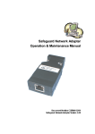
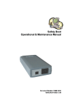
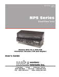
WTI Part No.: 13186
Rev. A
NPS-2HD
Heavy Duty Network Power Switches
User's Guide
Warnings and Cautions:
No Serviceable Parts Inside;
Authorized Service Personnel Only
Do not attempt to repair or service this device yourself. Internal
components must be serviced by authorized personnel only.
• Shock Hazard - Do Not Enter
Nameplate Power Warning
This device should only be operated with the type of power
source indicated on the instrument nameplate. If you are not
sure of the type of power service available, consult your local
power company.
• Connect unit only to a properly measured supply. Use
only three wire cord which is provided with the unit.
• Reliable earthing of this equipment must be maintained.
Particular attention should be given to supply
connections when connecting to power strips, rather than
direct connections to the branch circuit.
Rack Mount Installation
When installing this device in an instrument rack, the following
factors must be accounted for:
1.
Enclosed Racks: Enclosed racks must provide adequate
ventilation. Make certain that the rack is not overly
crowded and note that each unit in the rack generates its
own heat. An enclosed rack should have louvered sides
and a fan to circulate cooling air.
When mounting the unit in an enclosed rack with a
ventilation fan at the top of the rack, note that excessive
heat generated by devices at the bottom of the rack can be
drawn upward and into the ventilation slots of units
located at the top. Make certain to provide adequate
ventilation for equipment installed at the bottom of
the rack.
(Continued)
i
N P S - 2 H D He a v y D u t y N e t w o r k Po w e r S w i t c h ; U s e r ' s G u i d e
Rack Mount Installation (Continued)
1.
Enclosed Racks (Continued):
The ambient within the rack may be greater than room
ambient. Installation should be such that the amount of air
flow required for safe operation is not compromised. The
maximum temperature for the equipment in this
environment is 45°C. Consideration should be given to the
maximum rated ambient.
Installation should be such that a hazardous stability
condition is not achieved due to uneven loading.
2.
Open Racks: Make certain that the rack frame does not
block the ventilation slots on the instrument cover. If the
device is installed on sliders, check the unit when seated
all the way into the rack to make certain that ventilation
slots are not blocked.
Ventilation
Slots in the instrument cover are provided to allow ventilation
for heat dissipation. To ensure safe, reliable operation, these
openings must not be covered or blocked.
Disconnect Power
If any of the following events are noted, immediately disconnect
the unit from the outlet and contact qualified service personnel:
ii
1.
If the power cord becomes frayed or damaged.
2.
If liquid has been spilled into the device or if the device
has been exposed to rain or water.
Table of Contents
1.
2.
3.
4.
Introduction . . . . . . . . . . . . . . . . . . . . . . . . . . . . . . . . 1-1
Unit Description . . . . . . . . . . . . . . . . . . . . . . . . . . . . . 2-1
2.1.
2.2.
Quick Start Guide . . . . . . . . . . . . . . . . . . . . . . . . . . . . 3-1
Installation
4.1.
4.2.
4.3.
4.4.
4.5.
4.6.
5.
. . . . . . . . . . . . . . . . . . . . . . . . . . . . . . . . 4-1
Power Connection . . . . . . . . . . . . . . . . .
4.1.1. Cable Clamp Installation . . . . . . . .
4.1.2. Output Cable Clamp . . . . . . . . . . .
4.1.3. Input Cable Clamp . . . . . . . . . . . .
Option Switches . . . . . . . . . . . . . . . . . .
Reset Unit to Defaults . . . . . . . . . . . . . . .
4.3.1. Default Button / Reset Button (Local) .
4.3.2. Default Parameters Option . . . . . . .
Console Port Connection . . . . . . . . . . . . .
Connecting an External Modem . . . . . . . . .
Connecting the Network Cable . . . . . . . . . .
.
.
.
.
.
.
.
.
.
.
.
.
.
.
.
.
.
.
.
.
.
.
.
.
.
.
.
.
.
.
.
.
.
.
.
.
.
.
.
.
.
.
.
.
.
.
.
.
.
.
.
.
.
.
.
.
.
.
.
.
.
.
.
.
.
.
.
.
.
.
.
.
.
.
.
.
.
.
.
.
.
.
.
.
.
.
.
.
4-1
4-1
4-2
4-3
4-4
4-5
4-5
4-5
4-6
4-6
4-6
Configuration . . . . . . . . . . . . . . . . . . . . . . . . . . . . . . . 5-1
5.1.
5.2.
5.3.
5.4.
5.5.
5.6.
5.7.
6.
Front Panel . . . . . . . . . . . . . . . . . . . . . . . . . . . . . 2-1
Back Panel . . . . . . . . . . . . . . . . . . . . . . . . . . . . . 2-2
System Mode and User Mode . . . . . . . . . . . . . . . . . . 5-1
Communicating with the NPS . . . . . . . . . . . . . . . . . . 5-2
NPS Command/Menu Conventions . . . . . . . . . . . . . . . 5-4
Defining General Parameters . . . . . . . . . . . . . . . . . . . 5-4
Plug Parameters . . . . . . . . . . . . . . . . . . . . . . . . . . 5-7
Network Parameters . . . . . . . . . . . . . . . . . . . . . . . . 5-9
5.6.1. Implementing IP Security . . . . . . . . . . . . . . . 5-10
Save Configuration Parameters . . . . . . . . . . . . . . . . . 5-12
Operation . . . . . . . . . . . . . . . . . . . . . . . . . . . . . . . . . 6-1
6.1.
6.2.
6.3.
6.4.
6.5.
6.6.
6.7.
6.8.
Access the NPS-2HD Command
Displaying Plug Status . . . . .
Boot/On/Off Commands. . . . .
The Default Command . . . . .
The Automated Mode . . . . . .
Other Commands . . . . . . . . .
6.6.1. Login as Different User
6.6.2. Reset Network Port. . .
6.6.3. Exit / Disconnect . . . .
Manual Operation . . . . . . . .
Operating Tips . . . . . . . . . .
Mode
. . . .
. . . .
. . . .
. . . .
. . . .
. . . .
. . . .
. . . .
. . . .
. . . .
.
.
.
.
.
.
.
.
.
.
.
.
.
.
.
.
.
.
.
.
.
.
.
.
.
.
.
.
.
.
.
.
.
.
.
.
.
.
.
.
.
.
.
.
.
.
.
.
.
.
.
.
.
.
.
.
.
.
.
.
.
.
.
.
.
.
.
.
.
.
.
.
.
.
.
.
.
.
.
.
.
.
.
.
.
.
.
.
.
.
.
.
.
.
.
.
.
.
.
.
.
.
.
.
.
.
.
.
.
.
.
.
.
.
.
.
.
.
.
.
.
.
.
.
.
.
.
.
.
.
.
.
.
.
.
.
.
.
.
.
.
.
.
6-1
6-2
6-3
6-5
6-5
6-7
6-7
6-7
6-7
6-8
6-8
iii
N P S - 2 H D He a v y D u t y N e t w o r k Po w e r S w i t c h ; U s e r ' s G u i d e
7.
Saving and Restoring Configuration Parameters
7.1.
7.2.
. . . . . . . . . 7-1
Sending Parameters to a File . . . . . . . . . . . . . . . . . . . 7-1
Restoring Saved Parameters . . . . . . . . . . . . . . . . . . . 7-2
Appendices:
A.
Interface Descriptions . . . . . . . . . . . . . . . . . . . . . . . . Apx-1
A.1. Console Port Interface . . . . . . . . . . . . . . . . . . . . . Apx-1
A.2. Modem Port Interface . . . . . . . . . . . . . . . . . . . . . Apx-1
B.
Specifications . . . . . . . . . . . . . . . . . . . . . . . . . . . . . Apx-2
C.
Customer Service . . . . . . . . . . . . . . . . . . . . . . . . . . . Apx-3
Index . . . . . . . . . . . . . . . . . . . . . . . . . . . . . . . . . . . . Index-1
List of Figures
2.1.
2.2.
3.1.
4.1.
4.2.
5.1.
5.2.
5.3.
5.4.
5.5.
5.6.
6.1.
A.1.
A.2.
iv
Front Panel . . . . . . . . . . . . . . . . . . . . . . . . . . . . . . . . 2-1
Back Panel . . . . . . . . . . . . . . . . . . . . . . . . . . . . . . . . 2-2
The System Help Screen . . . . . . . . . . . . . . . . . . . . . . . . 3-2
Output Cable Clamp Installation . . . . . . . . . . . . . . . . . . . 4-2
Input Cable Clamp Installation . . . . . . . . . . . . . . . . . . . . 4-3
System Help Screen . . . . . . . . . . . . . . . . . . . . . . . . . . . 5-3
User Help Screen . . . . . . . . . . . . . . . . . . . . . . . . . . . . 5-3
General Parameters Menu (System Mode Only) . . . . . . . . . . 5-5
Plug Parameters Menu (Plug 1 Shown) . . . . . . . . . . . . . . . . 5-8
Network Parameters Menu (System Mode Only) . . . . . . . . . 5-9
IP Security Menu . . . . . . . . . . . . . . . . . . . . . . . . . . . 5-10
System Status Screen (Passwords Hidden) . . . . . . . . . . . . . 6-2
Console Port Interface. . . . . . . . . . . . . . . . . . . . . . . . Apx-1
Modem Port Interface . . . . . . . . . . . . . . . . . . . . . . . . Apx-1
1. Introduction
Network equipment sometimes "locks-up", requiring a service
call just to flip the power switch to perform a simple reboot. The
NPS-2HD Heavy Duty Network Power Switch gives you the
ability to perform this function from anywhere on the
LAN/WAN, or if the network is down, to simply dial-in from a
modem for out-of-band power control.
Intelligent Power Control
The NPS-2HD can communicate over any TCP/IP network using
standard Telnet, or out-of-band using an external modem and
terminal emulation. Each outlet can be assigned an individual
password, device name, reboot delay time and unique power-up
default status.
Security
Address specific IP security masks prevent unauthorized users
from accessing the NPS command menu via network. The NPS
provides two separate password security levels; System level and
User level. The System password allows access to all
configuration and command functions. The User password
allows limited access to command functions.
Easy to Use, Easy to Configure
The NPS can be configured over the network, via modem, or
locally via the NPS Console Port. Easy-to-use commands let you
assign a location name, set system parameters and view plug
status. Outlets can be switched On, Off, or Booted using plug
numbers or names.
Features:
· Dual 20 Amp Circuits
· On/Off/Reboot Switching
· Integral 10Base-T Interface
· RS232 Modem and Console Ports
· Outlet-Specific Password Security
· Network Security Features
· Manual On/Off Buttons
1-1
N P S - 2 H D He a v y D u t y N e t w o r k Po w e r S w i t c h ; U s e r ' s G u i d e
Typographic Conventions
Throughout this manual, typefaces and characters have been used
to denote the following:
1-2
COURIER FONT
Indicates characters typed on the keyboard.
For example, /ON 1 or /OFF 2.
[Bold Font]
Text set in bold face and enclosed in
square brackets indicates a specific key.
For example, [Enter] or [Esc].
2. Unit Description
2.1. Front Panel
As shown in Figure 2.1, the NPS-2HD front panel includes a
series of LED indicators which function as follows:
Figure 2.1: Front Panel
À
ON: Lights when AC Power is applied to the NPS-2HD.
Á
RDY: Flashes when the NPS-2HD is ready to receive
commands.
Â
RXD: Lights when the NPS-2HD receives commands.
Ã
DCD: Lights when the Modem Port detects the Carrier.
Ä
NET: Lights when a Telnet session is in progress.
Å
Plug Indicators and Manual Control Buttons: An
On/Off Indicator and Manual Control Button for each
switched plug. To manually switch a plug "On" or "Off",
press and hold the appropriate Manual Control Button for
one second; the corresponding plug will be toggled
On or Off.
Note: If desired, the Manual Control Buttons can
also be disabled as described in Section 5.4.
2-1
N P S - 2 H D He a v y D u t y N e t w o r k Po w e r S w i t c h ; U s e r ' s G u i d e
2.2. Back Panel
Figure 2.2: Back Panel
À
Bus 2 (Plug 2): Includes the following components:
A) Power Inlet: Supplies power for Bus 2.
B) Circuit Breaker: 115 VAC, 20 Amps
C) Switched Outlet: Each bus can switch up to 20 Amps.
Á
Bus 1 (Plug 1): Same as Item 1 above, except the Bus 1
Power Inlet supplies power to Bus 1.
Â
Network Port and Activity Indicator: A 10BaseT, RJ45
Ethernet port for connection to your TCP/IP network. To
communicate via Network, you must first specify network
parameters as described in Section 5.6.
Note: The NPS-2HD features a 10BaseT interface. When
connecting the NPS to a 100BaseT interface, note that
most 100BaseT router switches will autosense to determine
if the device is 100BaseT or 10BaseT and then configure
the network interface accordingly. If your router switch
does not autosense, then the network interface port must be
manually set to 10BaseT.
2-2
Ã
Modem Port: A Male RS-232, DB9 Connector, DTE
configuration. For connection to an external modem.
Ä
Console Port: A Male RS-232, DB9 Connector, DTE
configuration. For connection to a local PC.
Å
Option Switches: A bank of four DIP Switches which
select default settings for the baud rate and other features.
Æ
Default Button: Used in conjunction with the Reset
Button to reset the unit to defaults (see Section 4.3.)
Ç
Reset Button: Used in conjunction with the Default
Button to reset the unit to defaults (see Section 4.3.)
3. Quick Start Guide
This section provides a brief overview of basic NPS-2HD
capabilities, and describes a simple test that can be performed to
determine if the unit is operating properly and demonstrate basic
communication capabilities.
Note that this Quick Start procedure is included only to provide a
quick demonstration of basic NPS-2HD capabilities. In order to
take full advantage of the complete range of features provided by
this unit, it is strongly recommended that you should complete
the entire Installation and Configuration sections after
completing the Quick Start procedure.
1.
Apply Power to the NPS-2HD: Connect the NPS-2HD to
an appropriate power source. Prior to connecting the unit
to your power supply, make certain to review the safety
precautions listed at the beginning of this User's Guide and
the cable clamp installation instructions in Section 4.1.
2.
Connect a PC to the NPS-2HD: Attach a standard null
modem cable from your PC COM port to the Console Port
connector on the NPS back panel. For a description of the
port interface, please refer to Appendix A.
Note: When the NPS-2HD is shipped from the
factory, Console Port communication parameters are
set as follows: 9600 bps, 8 Data Bits, One Stop Bit,
No Parity. Although the NPS-2HD allows these
parameters to be easily redefined, for this Quick
Start procedure, it is recommended that you
configure your communications program to accept
these default parameters.
3.
Access the Command Mode: Start your communications
program and then press [Enter]; the System Help Screen
should be displayed (Figure 3.1) and the NPS command
prompt should appear. For more information on command
mode access, please refer to Section 5.2.
3-1
N P S - 2 H D He a v y D u t y N e t w o r k Po w e r S w i t c h ; U s e r ' s G u i d e
Network Power Switch v1.00
Site: WESTERN TELEMATIC, INC.
Commands:
Display
/H
/S[P]
Display this Help Screen
Display Plug Status, [P] with Passwords
Configuration
/G
View/Set
/P [n]
View/Set
/N
View/Set
/DL
Download
Control
/D
/Boot <n>
/On <n>
/Off <n>
/T
/R
/X
General Parameters
Plug Parameters
Network Parameters
Configuration to File
Set Plugs to Default Settings
Boot Plug n
Turn On Plug n
Turn Off Plug n
Reset Network Interface
Relogin as Different User
Exit/Disconnect
+------------------------------------+
| [n] = Optional Plug Name or Number |
| <n> = Required Plug Name or Number |
| n+n = Plug n and Plug n
|
| n:n = Plug n through Plug n
|
| * = All Plugs with Access
|
+------------------------------------+
TPS>
Figure 3.1: The System Help Screen
4.
Configure Network Port: In order to allow
communication with the NPS-2HD via the Network Port,
you must first define the IP Address, Subnet Mask, and
Gateway Address. At the NPS command prompt, type /N
and press [Enter] to display the Network Parameters
menu.
a) Settings for network parameters will depend on the
configuration of your individual network. Please
contact your network administrator in order to
determine the appropriate settings for the IP Address,
Subnet Mask, and Gateway Address.
b) To assign network parameters, key in the number for
the desired parameter, press [Enter], and then follow
the instructions in the resulting submenu. For
example, to define the IP Address, type 1 and
press [Enter].
3-2
Quick Start Guide
5.
Exit Command Mode: When you have finished setting
Network Parameters, type /X and press [Enter] to exit the
command mode at the Console Port.
Note: Only one port may access the NPS command
mode at a given time. In order to allow access to the
NPS unit via other ports, always exit from the
command mode when you are finished
communicating with the unit.
6.
Connect Network Cable: Connect your network interface
to the NPS-2HD Network Port. The Network Port is an
RJ45, 10BaseT Ethernet jack, for connection to a TCP/IP
network.
Note: The NPS-2HD features a 10BaseT Interface.
When connecting to a 100BaseT interface, note that
most router switches will autosense to determine if
the device is 100BaseT or 10BaseT, and then
configure the network interface accordingly. If your
router switch does not autosense, then the network
interface port must be manually set to 10BaseT.
7.
Network Access: Telnet to the NPS's IP address. For
example, if the IP address is "119.1.1.1", on a UNIX
system the Telnet command would be invoked as follows:
$ telnet 119.1.1.1 [Enter]
After the Telnet connection is established, the NPS should
display the System Help Screen and the NPS command
prompt should appear, indicating that you have
successfully accessed the NPS Command Mode via the
Network Port.
3-3
N P S - 2 H D He a v y D u t y N e t w o r k Po w e r S w i t c h ; U s e r ' s G u i d e
8.
Test Boot Commands: When the NPS-2HD is powered
up, both switched plugs will be set in the ON position. In
order to test for proper operation, you may wish to perform
the following test. Note that it is not necessary to connect
a device to either switched outlet in order to perform
this test.
a) Reboot Plugs: To initiate a boot cycle at both plugs,
go to the NPS command prompt and type /BOOT *
and press [Enter]. Power to both plugs will be
switched OFF. After the Boot Delay Period (Default =
5 Seconds), the power to both plugs will then be
automatically switched back ON. Note that the Plug
Status Indicators on the NPS-2HD front panel will also
switch Off and On.
b) Switch Plugs OFF: To switch both plugs OFF, go to
the NPS command prompt, type /OFF * and then
press [Enter]. Power to both plugs will be switched
OFF. Note that the Plug Status Indicators will also be
switched Off.
c) Switch Plugs ON: To switch both plugs ON, go to the
NPS command prompt, type /ON * and then press
[Enter]. Power to both plugs will be switched ON.
Note that the Plug Status Indicators will also be
switched On.
9.
Exit Command Mode: Type /X and press [Enter] to exit
from the NPS Command Mode, or disconnect using your
Telnet program.
This completes the introductory overview of the NPS-2HD.
Prior to installing and operating the unit, please review the
remainder of this User's Guide for important information
regarding safety considerations, as well as more detailed
installation, configuration, and operation instructions.
3-4
4. Installation
4.1. Power Connection
Note that the NPS-2HD features two separate 20 amp buses. In
order for both buses to function, power must be connected to
both input connectors on the unit's back panel.
Prior to connecting power supply cables to the unit, please refer
to the cautions below, and the cable clamp installation
instructions in Sections 4.1.1 and 4.1.2.
CAUTIONS:
• This device should only be operated with the
type of power source indicated on the
instrument nameplate. If you are not sure of the
type of power service available, please contact
your local power company.
• Reliable earthing (grounding) of this unit must
be maintained. Particular attention should be
given to supply connections when connecting to
power strips, rather than directly to the branch
circuit.
"Always On" Architecture: The NPS-2HD features "Always
On" architecture. This means that once the NPS-2HD is
connected to your power supply, both plugs will always be set in
the ON state, unless program commands or the Manual Control
Buttons have been used to switch the plug(s) to the OFF state.
4.1.1.
Cable Clamp Installation
CAUTIONS:
• Make certain that the unit is disconnected from
the power source before beginning this
procedure.
• In order to reduce the chance of injury due to
electric shock, the Output Cables should be
installed before the Input Cables.
4-1
N P S - 2 H D He a v y D u t y N e t w o r k Po w e r S w i t c h ; U s e r ' s G u i d e
Figure 4.1: Output Cable Clamp Installation
4.1.2.
Output Cable Clamp
1. Loosen Screws: Locate the two screws which secure each
output jack to the NPS-2HD back panel. Carefully loosen
each screw to provide sufficient room for the cable clamp
to be attached after it is fitted to the cable.
Note: Make certain to loosen the screws enough to
allow the cable clamp to be installed, but do not
entirely remove the screws from the NPS
back panel.
4-2
2.
Connect Plug: Plug the power cable from your AC
powered device into the output jack. Make certain that the
plug is firmly seated. Note that the total load for each
outlet must not exceed 20 amps.
3.
Fit Clamp to Plug: Carefully slip the output cable clamp
(See Figure 4.1) over the output plug, making certain that
the two slots at the base of the clamp are properly seated
over the screws which secure the output jack to the back
panel. The U-shaped cutout, located at the back of the
clamp, should face downwards in order to allow the clamp
to fit over the cable.
4.
Tighten Screws: Tighten the screws which secure the
output cable clamp to the output jack.
Installation
Figure 4.2: Input Cable Clamp Installation
4.1.3.
Input Cable Clamp
1. Loosen Screws: Locate the two screws which secure each
input jack to the NPS-2HD back panel. Carefull loosen
each screw to provide sufficient room for the input jack
clamp to be attached.
Note: Make certain to loosen the screws enough to allow
the clamp to be installed, but do not entirely remove the
screws from the NPS back panel.
2.
Attach Clamp to Jack: Slip the input clamp into place,
making certain that the screw slots in the base of the clamp
are securely seated over the screws which secure the input
jack to the back panel. Make certain to position the clamp
so the retaining screw (see Figure 4.2) is facing upwards.
Tighten the screws to secure the clamp to the input jack.
3.
Connect Plug: Slide the input plug into the cable clamp.
If necessary, loosen the retaining screw to provide room
for the plug. Make certain that the plug is firmly seated in
the jack, and then tighten the retaining screw to secure the
clamp to the cable.
4-3
N P S - 2 H D He a v y D u t y N e t w o r k Po w e r S w i t c h ; U s e r ' s G u i d e
4.2. Option Switches
The Option Switches select default settings for the Baud Rate,
Command Echo, Boot Delay and Disconnect Timeout. Default
settings selected via the Option Switches will be used when the
unit is reset to default parameters as described in Section 4.3.
Notes:
• Although the Option Switches select default
settings for these features, the NPS-2HD
configuration menus can also be used to select
operating parameters as described in Section 5.
• If Option Switch settings are changed, the new
settings will not be applied until the unit is reset
as described in Section 4.3.
Option Switch settings are described below:
Baud Rate: The default baud rate for the Console Port and
Modem Port.
Boot Delay: The default Boot Delay setting. When a boot cycle
is initiated, the Boot Delay determines the length of time that
the switched outlet will remain off until power is restored.
Command Echo: The default setting for the Command Echo for
the Console Port, Modem Port and Network Port. When
enabled, commands entered at your keyboard will be sent to
the NPS and echoed back to your display monitor.
Disconnect Timeout: The default Disconnect Timeout value.
This determines how long the NPS will wait for additional
commands before automatically disconnecting. Note that
when the NPS times out, DTR will drop, and the modem
disconnect and initialize strings will be sent.
Switch
Function
Down
1
Default Baud Rate
38.4K bps
9600 bps*
2
Default Boot Delay
10 Sec.
5 Sec.*
3
Default Command Echo
Enable
Disable*
4
Default Disconnect Timeout
30 Min
2 Min*
* = Factory Setting
4-4
Up
Installation
4.3. Reset Unit to Defaults
If Option Switch settings are changed, the new settings will not
be applied until the unit is reset to default settings. There are
two ways to reset the unit to defaults:
Note: When these reset procedures are performed,
all user selected parameters, including passwords
and port names will be lost. Prior to performing
these reset procedures, it is strongly recommended
to save configuration parameters to an ASCII text
file as described in Section 7.
4.3.1.
Default Button / Reset Button (Local)
Typically, this method is used when you have immediate access
to the installation site.
1.
Simultaneously press the DEFAULT and RESET buttons,
located on the NPS-2HD Back Panel.
2.
Release the RESET button, wait for approximately five
seconds, and then release the DEFAULT button.
4.3.2.
Default Parameters Option
To reset the unit to default parameters using the General
Parameters Menu's "Default Parameters" option, proceed
as follows. Note that this method requires that you have already
connected a local or remote PC to the unit and have accessed the
command mode.
1.
Access the NPS Command Mode (see Section 6.1).
2.
At the NPS> command prompt, type /G and press [Enter].
The General Parameters menu will appear.
3.
From the General Parameters menu, type A and press
[Enter]. If command confirmation is enabled, the unit
will display a "Sure?" prompt. Type Y and press [Enter]
to proceed with the reset procedure. After a brief pause,
parameters will be reset to default values.
Note: If the Default Parameters function is invoked
via the Network Port, the IP Address will not be
reset. If this function is invoked via the Console
Port or Modem Port, the IP Address will be reset.
4-5
N P S - 2 H D He a v y D u t y N e t w o r k Po w e r S w i t c h ; U s e r ' s G u i d e
4.4. Console Port Connection
The Console Port is a male, DB9 connector, wired in a DTE
configuration (similar to an AT computer), which is used for
connection to a local PC or control device. Appendix A
describes the Console Port interface.
4.5. Connecting an External Modem
When connecting directly to an external modem, use a standard
DB9 AT to Modem cable. Section 5.4 describes the procedure
for defining the modem command strings. Appendix A describes
the modem port interface.
4.6. Connecting the Network Cable
The Network Port is an RJ45 Ethernet jack, for connection to a
TCP/IP network. Connect your 10Base-T cable to the Network
Port. Before attempting to access the unit via network, please
assign the IP Address, Gateway Address and Subnet Mask as
described in Section 5.6.
Note: The NPS-2HD features a 10BaseT interface.
When connecting the NPS to a 100BaseT interface,
note that most router switches will autosense to
determine if the device is 100BaseT or 10BaseT and
then configure the network interface accordingly. If
your router switch does not auto-configure for
10BaseT vs. 100BaseT, then the network interface
port must be manually set to 10BaseT.
4-6
5. Configuration
5.1. System Mode and User Mode
In order to restrict access to sensitive command functions, the
NPS-2HD features two separate operating modes; System Mode
and User Mode.
The System Mode allows access to all configuration menus,
command functions and status screens. When the System Mode
is active, Boot/On/Off commands can always be directed to
either of the two switched outlets, even if each plug has been
assigned a separate password. The System Mode Status Screen
shows On/Off conditions for both switched outlets, and lists
currently defined system parameters.
The User Mode allows limited access to command functions and
status screens; users are not allowed to access configuration
menus. When the User Mode is active, Boot/On/Off commands
can only be directed to the specific outlet(s) allowed by the User
Password entered at login. If a different User Password is
assigned to each NPS outlet, then a user who accesses the NPS
using the password for Plug 1 is not allowed to boot or switch
Plug 2. On the other hand, if the same User Password is assigned
to both NPS outlets, then that user will be able to direct
commands to both plugs. The User Mode Status Screen only
shows conditions at the outlet(s) owned by the User Password;
system parameters are not displayed.
When properly configured, the NPS will display a password
prompt when the unit is contacted via the Console Port, Modem
Port or Network Port. The password entered at this prompt
determines whether the unit will start-up in System Mode or User
Mode. If the System Password (defined via the General
Parameters menu) is entered, the System Mode will be active. If
the User Password (defined via the Plug Configuration Menus) is
entered, the User Mode will be active.
If the System Password is not defined, the NPS-2HD will not
display the password prompt, and will always start-up in System
Mode. Once the System Password has been defined, individual
users can be granted access by assigning passwords to the NPS's
two switched plugs as described in Section 5.5.
5-1
N P S - 2 H D He a v y D u t y N e t w o r k Po w e r S w i t c h ; U s e r ' s G u i d e
5.2. Communicating with the NPS
In order to configure the unit or invoke command functions, the
user must first connect to the NPS and access the command
mode.
1.
The NPS-2HD is transparent to parity and will accept 7 or
8 bit characters, but will always answer back at 8 bits, no
parity. Make certain your communication program (e.g.
ProComm or HyperTerminal) is set for the appropriate
baud rate, bits and parity.
a) Via Modem: Start your communications program.
Dial the external modem connected to the NPS. Wait
for the Connect message and proceed to Step 2.
b) Via Local PC: Start your communications program
and then press [Enter].
c) Via Network: During initial configuration, the NPS
cannot be accessed via the Network Port. After
network parameters have been defined (see
Section 5.6), the unit may then be accessed via network
as described in Section 6.1.
Note: Only one port can access the command mode
at a given time. When communicating via the
Console Port or Modem Port, always make certain to
disconnect (using the /X command) when you have
finished. If the Console Port or Modem Port are
busy, you will not be able to access the command
mode via the Network Port. For more information,
please refer to Section 6.8.
5-2
2.
Password: If the System Password has been defined, the
unit will display the Password Prompt. Key in either the
System Password or User Password, and press [Enter]. If
the system password has not been defined, the prompt will
not be displayed. Note that the Password feature is case
sensitive.
3.
If the System Password is entered, the NPS-2HD will
display the System Help Screen (Figure 5.1). If the User
Password is entered, the NPS will display the User Help
Screen (Figure 5.2).
Configuration
Network Power Switch v1.00
Site: WESTERN TELEMATIC, INC.
Commands:
Display
/H
/S[P]
Display this Help Screen
Display Plug Status, [P] with Passwords
Configuration
/G
View/Set
/P [n]
View/Set
/N
View/Set
/DL
Download
Control
/D
/Boot <n>
/On <n>
/Off <n>
/T
/R
/X
General Parameters
Plug Parameters
Network Parameters
Configuration to File
Set Plugs to Default Settings
Boot Plug n
Turn On Plug n
Turn Off Plug n
Reset Network Interface
Relogin as Different User
Exit/Disconnect
+------------------------------------+
| [n] = Optional Plug Name or Number |
| <n> = Required Plug Name or Number |
| n+n = Plug n and Plug n
|
| n:n = Plug n through Plug n
|
| * = All Plugs with Access
|
+------------------------------------+
Figure 5.1: System Help Screen
Network Power Switch v1.00
Site: WESTERN TELEMATIC, INC.
Commands:
Display
/H
/S
Display this Help Screen
Display Plug Status
Control
/D
/Boot <n>
/On <n>
/Off <n>
/X
Set Plugs to Default Settings
Boot Plug n
Turn On Plug n
Turn Off Plug n
Exit/Disconnect
+------------------------------------+
| <n> = Required Plug Name or Number |
| n+n = Plug n and Plug n
|
| n:n = Plug n through Plug n
|
| * = All Plugs with Access
|
+------------------------------------+
NPS>
Figure 5.2: User Help Screen
5-3
N P S - 2 H D He a v y D u t y N e t w o r k Po w e r S w i t c h ; U s e r ' s G u i d e
5.3. NPS Command/Menu Conventions
When invoking NPS-2HD commands and selecting items from
configuration menus, note the following:
· To display the Help Screen, type /H [Enter].
· All NPS commands can be invoked at the NPS> command
prompt, or from the General Parameters Menu, Port
Parameters Menus or Network Parameters Menu.
· NPS commands are not case sensitive. All NPS commands
are invoked by pressing [Enter].
· To select an item from an NPS menu, key in the number for
the item and press [Enter]. To exit from a menu, press
[Esc] at any time. Parameters defined up to that point will
be saved.
· The ",Y" option can temporarily suppress the "Sure?"
confirmation prompt. The ",Y" option is entered at the end
of the command line, immediately following the command
or argument. For example, to reset the network port without
displaying the "Sure?" prompt, type /T,Y [Enter].
5.4. Defining General Parameters
When the "NPS>" prompt appears, type /G [Enter] to display
the General Parameters menu (Figure 5.3). Note that this menu
is not available in User Mode. The General Parameters menu
offers the following options:
1.
System Password: (Up to 16 characters, case-sensitive)
When the System Password is defined, the NPS-2HD will
display a prompt before allowing access to command
mode. If the System Password is entered, the NPS will
start-up in System Mode. To define the System Password,
type 1 and press [Enter]. (Default = undefined).
Note: If the System Password is not defined, the
password prompt will not be displayed, and the NPS
will always start-up in System Mode.
2.
5-4
Site ID: Defines a text string (up to 32 characters) that
denotes the installation site. To define the Site ID, type 2
and press [Enter]. (Default = undefined).
Configuration
GENERAL PARAMETERS:
1.
2.
3.
4.
5.
6.
7.
8.
9.
10.
System Password:
Site ID:
Modem Init. String:
Modem Disc. String:
Baud Rate:
Command Echo:
Disconnect Timeout:
Command Confirmation:
Automated Mode:
Button Mode:
A.
Default Parameters
(undefined)
(undefined)
ATE0M0Q1&C1&D2S0=1
(undefined)
9600,N,8,1
Off
2 Min
On
On
On
Enter Selection or <ESC> to Exit ...
Figure 5.3: General Parameters Menu (System Mode Only)
3.
Modem Initialization String: To define the Modem
Initialization String (up to 32 characters), type 3 and
press [Enter]. For more information on the initialization
string, please refer to the user's guide for your external
modem. Make certain that the modem is set to autoanswer in one ring. (Default = ATE0M0Q1&C1&D2S0=1).
4.
Modem Disconnect String: To define the Disconnect
String (up to 32 characters), type 4 press [Enter], and
follow the instructions in the submenu. For more
information, please refer to the user's guide for your
external modem. (Default = undefined).
5.
Baud Rate: To select the baud rate for the Modem Port
and Console Port, type 5 press [Enter], and follow the
instructions in the submenu. Make certain to select a rate
that is compatible with the external modem, and/or the
device connected to the Console Port. (Default value
determined by Option Switch 1; Factory Setting = 9600).
Note: When this setting is changed, the new baud
rate will not be applied until the user exits and then
re-enters the NPS Command Mode.
6.
Command Echo: Enables/Disables the command echo.
When enabled, commands sent to the NPS will be echoed
back to your PC, allowing keystrokes to be displayed . To
enable/disable the echo, type 6, press [Enter] and follow
the instructions in the submenu. (Default determined by
Option Switch 3; Factory Setting = Disabled).
5-5
N P S - 2 H D He a v y D u t y N e t w o r k Po w e r S w i t c h ; U s e r ' s G u i d e
7.
Disconnect Timeout: Determines how long the NPS-2HD
will wait for additional commands. Type 7, press [Enter],
and follow the instructions in the submenu. (Default
determined by Option Switch 4; Factory Setting = 2 Min.).
Note: It is recommended that the Disconnect
Timeout should be set at the lowest acceptable
value. Since only one port is allowed to access the
command mode at a given time, shorter timeout
values will decrease the chance of other users being
shut out of command mode if a user fails to
disconnect when finished communicating with
the unit.
8.
Command Confirmation: When enabled, the NPS-2HD
will display a "Sure?" prompt before completing the /T, /X,
/R, /BOOT, /ON, /OFF, /D and "A" commands, and will
also display the System Status screen after commands are
successfully completed. When disabled, the "Sure?"
prompt is suppressed, and the Status Screen is not sent
when commands are complete. (Default = Enabled).
9.
Automated Mode: When enabled, the NPS will execute
the /ON, /OFF, /BOOT, /D, and /X commands without
displaying the confirmation prompt, status screen, or
confirmation messages. This allows the NPS to be
controlled by a device that generates commands to control
power switching without human interaction. For more
information, please refer to Section 6.5. (Default = Off).
Note: When this option is enabled, NPS password
security functions are disabled, and users are able to
access System Level menus and control both plugs
without entering a password.
10. Button Mode: Enables/disables the manual plug control
buttons on the NPS-2HD front panel. When enabled, the
NPS's two switched plugs can be toggled On and Off by
pressing and holding the manual control button for
approximately one second. When disabled, the manual
control buttons will have no effect. (Default = On).
5-6
Configuration
A. Default Parameters: Resets the NPS to the default values
specified by the Option Switches. In addition, all menu
selected parameters, including port names and passwords,
will be lost. Note that if Command Confirmation is
disabled, the "Sure?" prompt will not be sent.
Note: If the Default Parameters function is invoked
via the Network Port, the IP Address is not reset. If
this function is invoked via the Console Port or
Modem Port, the IP Address will be reset.
After defining the General Parameters, press [Esc] to exit from
the General Parameters menu.
5.5. Plug Parameters
The Plug Parameters menus are used to assign names and select
parameters for each of the two switched outlets. There is a
separate Plug Parameters menu for each outlet. Note that the
Plug Parameters menus are not available in User Mode.
In addition to selecting parameters for each outlet, the Plug
Parameters menus also allow you to assign an individual User
Password to each plug. If the same User Password is assigned to
both plugs, then that password will allow the user to direct
Boot/On/Off commands to both switched plugs. If a different
password is assigned to each plug, then each password will only
allow access to it's corresponding plug.
To access the Plug Parameters menus from the NPS> prompt,
type /P n and press [Enter] where n is the number or name of
one of the two switched outlets. The Plug Parameters menu
(Figure 5.4) offers the following options:
1.
Plug Name: (Up to 16 Characters) Assigns a name to the
plug. Typically, this name describes the piece of
equipment that is connected to the switched outlet. When
plug names are assigned, Boot/On/Off commands can be
invoked using the name or number of the desired plug.
(Default = undefined).
5-7
N P S - 2 H D He a v y D u t y N e t w o r k Po w e r S w i t c h ; U s e r ' s G u i d e
PLUG #1 PARAMETERS:
1.
2.
3.
4.
Plug Name:
Password:
Boot Delay:
Power Up Default:
(undefined)
(undefined)
5 Sec
On
Enter Selection or <ESC> to Exit ...
Figure 5.4: Plug Parameters Menu (Plug 1 Shown)
2.
Password: (Up to 16 Characters) Assigns a User
Password to this plug. When a User Password is assigned,
the plug is then "owned" by that password. When a User
Password is entered at login, the user will have access to
only the plug(s) which are owned by this password.
(Default = undefined).
Notes:
· If you wish to allow a single user to access both
switched plugs, assign the same User Password to
both plugs.
· If the System Password is defined, and the plug's
User Password is not defined, then the System
Password will "own" this plug, and only the
System Mode will be able to control the plug.
3.
Boot Delay: During a Boot cycle, power to the plug is
first switched off and then switched back on. The Boot
Delay is the length of time which elapses between the time
when power is switched off and the time that power is
restored. The Boot Delay can be 1, 5, 10, 15, 30 or 60
seconds. (Default determined by Option Switch 2; Factory
Setting = 5 Seconds).
4.
Power-Up Default: Determines how this plug will react
when the /D (default) command is invoked, or after a
power interruption. Each plug can be automatically
switched On or Off as specified by the Power-Up Default.
(Default = On).
After Plug Parameters have been defined, press [Esc] to exit
from the Plug Parameters menu.
5-8
Configuration
NETWORK PARAMETERS:
1.
2.
3.
4.
IP Address:
Subnet Mask:
Gateway Address:
IP Security
MAC Address:
(undefined)
(undefined)
(undefined)
00-40-05-5e-f3-90
Enter Selection or <ESC> to Exit ...
Figure 5.5: Network Parameters Menu (System Mode Only)
5.6. Network Parameters
In order to communicate with the NPS-2HD via network, the IP
Address, Subnet Mask and Gateway Address must first be
defined using the Network Parameters menu. If desired, this
menu also allows you to implement IP Security features, which
restrict command mode access based on the user's IP Address.
Settings for network parameters depend upon the configuration
of your individual network. Please contact your network
administrator for appropriate settings, and then assign parameters
as described in this section.
To access the Network Parameters menu (Figure 5.5), type /N
and press [Enter]. Note that this menu is not available in User
Mode. The following options are available:
1.
IP Address: Defines the IP Address for the NPS unit.
Type 1 press [Enter], and follow the instructions in the
submenu. (Default = undefined)
2.
Subnet Mask: Defines the Subnet Mask for the NPS unit.
Type 2 press [Enter], and follow the instructions in the
submenu. (Default = undefined)
3.
Gateway Address: Defines the Gateway Address for the
NPS unit. Type 3 press [Enter], and follow the
instructions in the submenu. (Default = undefined)
4.
IP Security: Sets up the IP Security feature as described
in Section 5.6.1.
5.
Mac Address: Displays the unit's MAC Address. Note
that this item is not used to redefine the MAC Address.
5-9
N P S - 2 H D He a v y D u t y N e t w o r k Po w e r S w i t c h ; U s e r ' s G u i d e
IP SECURITY
1.
2.
3.
4.
5.
6.
7.
8.
9.
10.
Security Mask #1:
Mask #1 Action:
Security Mask #2:
Mask #2 Action:
Security Mask #3:
Mask #3 Action:
Security Mask #4:
Mask #4 Action:
Security Mask #5:
Mask #5 Action:
(undefined)
Permit
(undefined)
Permit
(undefined)
Permit
(undefined)
Permit
(undefined)
Permit
Enter Selection or <ESC> to Exit
Figure 5.6: IP Security Menu
5.6.1.
Implementing IP Security
The NPS-2HD can be configured to restrict unauthorized IP
addresses from Telneting to the unit. This allows the user to
grant Telnet access to only a specific group of IP addresses, or
block a particular IP address from gaining access. In the default
state, the NPS accepts incoming IP connections from all hosts.
To configure the IP Security feature, proceed as follows:
1.
Access the Network Parameters menu as described in
Section 5.6. Note that the Network Parameters menu is
not available in User Mode.
2.
When the Network Parameters menu appears, type 4 and
press [Enter] to access the IP Security menu (Figure 5.6).
3.
The IP Security menu lists five IP Security "masks" along
with the selected permit/deny action for each mask.
a) Each Security Mask prompt is used to define a specific
IP address or range of IP addresses. Each Mask Action
prompt is used to define the permit/deny action for the
corresponding Mask.
b) Masks are listed in order of ascending priority; Mask 1
has the lowest priority, Mask 5 has the highest priority.
c) Masks have a cumulative effect; high priority masks
supersede the effect of lower priority masks.
d) Each IP Address consists of a series of four eight bit
numbers. The number 255 is used as a wild card.
5-10
Configuration
Example 1: Deny access to all hosts except 192.1.1.5:
Security Mask #1: 255.255.255.255
Security Mask #2: 192.1.1.5
Mask #1 Action: Deny
Mask #2 Action: Permit
Since 255 is a wild card, Mask #1 blocks all IP Addresses. Mask
#2 then specifically grants access to 192.1.1.5 only.
Example 2: Allow access only by addresses that begin with 192.
Security Mask #1: 255.255.255.255
Security Mask #2: 192.255.255.255
Mask #1 Action: Deny
Mask #2 Action: Permit
Since 255 is a wild card, Mask 1 blocks all IP addresses. Mask 2
then grants access to all addresses that begin with 192.
Example 3: Allow access only by addresses that begin with 192,
deny access to 192.1.1.5.
Security Mask #1: 255.255.255.255
Security Mask #2: 192.255.255.255
Security Mask #3: 192.1.1.5
Mask #1 Action: Deny
Mask #2 Action: Permit
Mask #3 Action: Deny
Since 255 is a wild card, Mask 1 blocks all IP addresses. Mask 2
then grants access to all addresses that begin with 192. Finally,
Mask 3 specifically blocks access by 192.1.1.5.
Note:
· Mask #5 has priority over the other four masks. If
Mask #5 is set to deny access by
"255.255.255.255" (all wild cards), all IP
Addresses will be blocked, and you will not be able
to access the NPS Command Mode via network.
Access will only be allowed via the Console Port
or Modem Port.
· When using the wild card address
"255.255.255.255" to block access by all IP
Addresses, make certain that at least one higher
priority mask permits access by your IP address.
5-11
N P S - 2 H D He a v y D u t y N e t w o r k Po w e r S w i t c h ; U s e r ' s G u i d e
5.7. Save Configuration Parameters
After the unit has been completely configured, it is recommended
to save parameters to an ASCII file as described in Section 7.
This allows quick recovery in the event that the unit is reset to
default parameters, or the configuration is accidentally deleted or
altered.
5-12
6. Operation
6.1. Access the NPS-2HD Command Mode
Commands can be sent to the NPS-2HD via Network or modem,
or from a local PC connected to the Console Port. To access the
Command Mode, proceed as follows:
Note: Only one port can access command mode at a
given time. When you have finished communicating
with the unit, always make certain to disconnect
using the /X command. When the Console Port or
Modem Port are busy, you will not be able to access
the command mode via the Network Port. For more
information, please refer to Section 6.8.
1.
Contact the NPS:
a) Via Network: Telnet to the NPS unit's IP Address.
For example, if the IP Address is 192.1.1.1, on a UNIX
system the Telnet command would be as follows:
$ telnet 192.1.1.1 [Enter]
Notes:
· In order to contact the NPS via telnet, you must
first define the unit's Network Parameters as
described in Section 5.6.
· If the Telnet connection to the NPS is refused, this
may mean that the unit is busy, or that the IP
Security feature has denied the connection.
b) Via Modem: Start your communications program (e.g.
HyperTerminal). Dial the external modem connected
to the NPS, then wait for the Connect Message.
c) Via Console Port: Start your communications
program and press [Enter].
2.
Password: If the System password has been defined, a
prompt will be displayed. Key in your System or User
Password, and press [Enter].
3.
Disconnect: To end the session, type /X and press
[Enter] (or disconnect using Telnet software).
6-1
N P S - 2 H D He a v y D u t y N e t w o r k Po w e r S w i t c h ; U s e r ' s G u i d e
6.2. Displaying Plug Status
The Status Screen displays the On/Off state and selected
parameters for the switched plugs. To display the Status Screen,
type /S and press [Enter]. Note that although the /S command
is available in both User and System Mode, the System Status
Screen includes more information than the User Status Screen.
When the System Mode is active, the /S command will produce
the screen shown in Figure 6.1, which lists status and parameters
for both switched plugs, along with Console Port parameters, and
modem command strings. Note that in System Mode, the /S
command will also accept an argument which will display the
User Password for each plug. To display plug passwords, access
the System Mode, type /SP and press [Enter].
When the User Mode is active, the /S command will produce a
different version of the status screen, which lists the status and
parameters only for the plug(s) owned by the User password
entered at login. If a separate User Password has been assigned
to the other plug, the User Mode Status Screen will not list the
status for that plug. In User mode, plug passwords cannot be
displayed.
Network Power Switch v1.00
Site: WESTERN TELEMATIC, INC.
Plug | Name
| Status | Boot Delay | Password
| Default
------+------------------+--------+------------+------------------+--------1
| ROUTER_POWER_A
| ON
| 15 Sec
| (defined)
| ON
2
| ROUTER_POWER_B
| ON
| 15 Sec
| (defined)
| ON
------+------------------+--------+------------+------------------+------Modem Init. String:
Modem Disc. String:
Communication Settings:
Command Echo:
Disconnect Timeout:
Command Confirmation:
Automated Mode:
Button Mode:
ATE0M0Q1&C1&D2S0=1
+++ATZ
9600,N,8,1
OFF
30 Min
ON
OFF
ON
"/H" for Help
Figure 6.1: System Status Screen (Passwords Hidden)
6-2
Operation
6.3. Boot/On/Off Commands
These commands are used to Boot or toggle the On/Off status of
the NPS's two switched plugs. If the same password has been
applied to both switched plugs, commands can be directed to
Plug 1, Plug 2, or both switched plugs. If a separate User
Password has been assigned to each plug, then commands can
only be applied to the plug that is owned by the User Password
entered at log in. Plugs may be specified by name or number.
Notes:
· When User Mode is active, commands will only be
applied to plugs owned by the User's password.
· To apply a command to both outlets, enter an
·
·
·
·
1.
asterisk (*) in place of the plug number or name.
Commands can only be applied to both plugs when
the unit is operating in System Mode, or when both
plugs are owned by the same User Password.
When commands are applied to both plugs, the
NPS will delay for approximately 1 second
between actions. For example, when switching
both plugs On, the NPS will switch Plug 1 On,
delay one second, then switch Plug 2 On.
Wait for the "NPS>" prompt to appear before
entering commands. The prompt will not reappear
until the previous command is complete.
Commands are not case sensitive. All commands
are invoked by pressing [Enter].
If command confirmation is enabled, the NPS will
display the Status Screen after the Boot/On/Off
commands are successfully completed.
Boot Plug(s): To initiate a Boot cycle, type /BOOT n and
press [Enter]. Where "n" is a the number or name of the
desired plug. Note that the "/BOOT" command can also be
entered as "/BO".
Examples:
· To boot both plugs, type /BOOT * or /BO * and then
press [Enter].
· To boot plug 1, type /BOOT 1 or /BO 1 and then
press [Enter].
6-3
N P S - 2 H D He a v y D u t y N e t w o r k Po w e r S w i t c h ; U s e r ' s G u i d e
2.
Switch Plug(s) On: To power-on a plug, type /ON n and
press [Enter]. Where "n" is the number or name of the
desired plug.
Examples:
· To power-on both plugs, type /ON * and press [Enter].
· To power-on Plug One, type /ON 1 and press [Enter].
3.
Switch Plug(s) Off: To power-off a plug, type /OFF n
and press [Enter]. Where "n" is the number or name of
the desired plug. Note that the "/OFF" command can also
be entered as "/OF".
Examples:
· To power-off both plugs, type /OFF * or /OF * and
press [Enter].
· To power-off a plug named POWER2, type
/OFF POWER2 or /OF POWER2 and press [Enter].
4.
Suppress Command Confirmation Prompt: To execute a
Boot/On/Off command without displaying the "Sure?"
prompt, include the ",Y" option in the command line. The
",Y" option is entered immediately following the
command argument.
Examples:
· To boot both plugs without displaying the "Sure?"
prompts, type /BOOT *,Y or /BO *,Y and then
press [Enter].
· To power-off a plug named POWER1 without displaying
the "Sure?" prompt, type /OFF POWER1,Y or
/OF POWER1,Y and then press [Enter].
6-4
Operation
6.4. The Default Command
The Default Command (/D) sets plugs to their default On/Off
status. The default status is set using the Plug Parameters menus
described in Section 5.5. To set plugs to defaults, type /D and
press [Enter].
Note:
· When User Mode is active, this command will only
be applied to the plug owned by the User's
password. The command will not be applied to a
plug that is owned by another User Password.
· When the System Mode is active, this command
will be applied to both plugs.
· This command will always be applied to all owned
plugs. It cannot be directed only to a specific plug.
6.5. The Automated Mode
The Automated Mode allows the NPS-2HD to perform
On/Off/Boot/Default/Exit commands, without displaying menus
or generating response messages. Automated Mode is designed
to allow the NPS to be controlled by a computer (or another
automatic system) which can generate commands to control
power switching functions without human intervention.
When the Automated Mode is enabled, the /ON, /OFF, /BOOT,
/D and /X commands are executed without a "Sure?"
confirmation prompt and without command response messages;
the only reply to these commands is the "NPS>" prompt, which is
displayed when the command is complete.
Note: When Automated Mode is enabled, all NPS
password security functions are disabled, and users
are able to access System Level command functions
(including the configuration menus), and control
both plugs without entering a password. If you need
to enable the Automated Mode, but want to restrict
network access to NPS configuration menus, it is
recommended to enable and configure the IP
Security Function as described in Section 5.6.1.
6-5
N P S - 2 H D He a v y D u t y N e t w o r k Po w e r S w i t c h ; U s e r ' s G u i d e
To enable/disable the Automated Mode, access the NPS General
Parameters menu, and proceed as described in Section 5.4.
When the Automated Mode is enabled, NPS functions will
change as follows:
1.
All Password Security Suppressed: When a user
attempts to access the NPS command mode, the password
prompt will not be displayed at either the Network Port,
Modem Port, or Console Port. Unless restricted by the IP
Security Function, all users will be allowed to access
System Level command functions and control both plugs.
At the Console Port, all commands are immediately
accepted, whether the port is awake or asleep.
2.
Status Screen Suppressed: The status screen will not be
automatically displayed after commands are successfully
executed. Note however, that the /S command can still be
invoked to display the status screen as required.
3.
"Sure?" Prompt Suppressed: All commands are
executed without prompting for user confirmation.
4.
Error Messages Suppressed: If the [Enter] key is
pressed without entering a command, the NPS will not
respond with the "Invalid Command" message. Note
however, that an error message will still be generated if
commands are invoked using invalid formats or arguments.
All other status display and configuration commands will still
function as normal.
6-6
Operation
6.6. Other Commands
6.6.1.
Login as Different User
The /R command is used to re-login using a different password.
When invoked, the NPS will display the password prompt,
allowing the user to enter a different password in order to access
the other plug or System Level command functions. The /R
command is typically used to switch from User Mode to
System Mode.
The /R command is available in both System Mode and User
Mode. To login as a different user, type /R, press [Enter], and
then key in a different valid password at the prompt. To
suppress the "Sure?" prompt, type /R,Y [Enter].
6.6.2.
Reset Network Port
The /T command is used to reinitialize the NPS Network card.
The /T command is not available in User Mode. To reset the
Network Port, type /T and press [Enter]. To suppress the
"Sure?" prompt, type /T,Y [Enter].
Note: The /T command can only be issued via the
Console Port or Modem Port. The /T command
cannot be invoked via the Network Port.
6.6.3.
Exit / Disconnect
To exit from the NPS Command Mode and discontinue
connection to the unit, type /X and press [Enter]. The NPS will
display the "DISCONNECT" message. To suppress the "Sure?"
prompt, type /X,Y [Enter].
Note: Only one port may access the NPS command
mode at any given time. In order to allow access to
the NPS unit via other ports, always exit from the
command mode when you are finished
communicating with the unit. For more information,
please refer to Section 6.8.
6-7
N P S - 2 H D He a v y D u t y N e t w o r k Po w e r S w i t c h ; U s e r ' s G u i d e
6.7. Manual Operation
In addition to the command driven functions, the NPS's two
switched plugs can also be toggled On and Off manually. To
manually toggle a plug On or Off, press the appropriate Manual
Control Button, and hold it down for approximately one second;
the corresponding plug will be toggled On or Off. Note that if
desired, the Manual Control Buttons can also be disabled via the
General Parameters menu as described in Section 5.4.
6.8. Operating Tips
When connecting to the NPS-2HD via network, modem or
console port, the following factors should be kept in mind:
1.
One Connection at a Time: Only one port can access the
command mode at a time. Therefore, it is recommended
that users should always disconnect using the /X command
when finished communicating with the unit. When a
command port is busy, the NPS-2HD will react as follows:
a) Network Port Busy: If a second user attempts to
connect via the Modem Port, the NPS will send a busy
message. If a second user attempts to connect via the
Console Port, the port will not wake.
b) Modem Port Busy: If a second user attempts to
connect via the Network Port, the connection will be
refused. If a second user attempts to connect via the
Console Port, the port will not wake.
c) Console Port Busy: If a second user attempts to
connect via the Network Port, the connection will be
refused. If a second user attempts to connect via the
Modem Port, the Console Port will disconnect and the
Modem Port will be granted access; the Modem Port
has priority over the Console Port.
2.
Ping Packet Size: The NPS will not accept Ping Packets
larger than approximately 1000 bytes.
If you have any questions regarding configuration or operation of
the NPS, please contact WTI Technical Support as described in
Appendix C.
6-8
7. Saving and Restoring
Configuration Parameters
After the NPS-2HD has been properly configured, parameters
can be downloaded and saved as an ASCII text file. Later, if the
configuration is accidentally altered, the file with the saved
parameters can be uploaded to automatically reconfigure the unit
without the need to manually assign each parameter.
Saved parameters can also be uploaded to other NPS-2HD units.
This allows rapid set-up when several units will be configured
with the same parameters.
The "Save Parameters" procedure can be performed from any
terminal emulation program (e.g. ProComm, Crosstalk,
Hyperterminal, etc.), which allows downloading of ASCII files.
7.1. Sending Parameters to a File
1.
Start your communications program and access the
NPS-2HD command mode using the System Level
Password.
2.
When the NPS command prompt appears, type /DL and
press [Enter]. The NPS will prompt you to prepare your
communications program. Set up your communications
program to receive an ASCII download, and specify a
name for the file that will receive the saved parameters
(e.g. NPS.PAR).
3.
When the communications program is ready to receive the
file, return to the NPS command mode, and press [Enter]
to proceed.
4.
The NPS will send a series of ASCII command lines which
specify the currently selected NPS parameters.
7-1
N P S - 2 H D He a v y D u t y N e t w o r k Po w e r S w i t c h ; U s e r ' s G u i d e
7.2. Restoring Saved Parameters
This section describes the procedure for using ProComm to send
saved parameters to the NPS-2HD.
1.
Start your communications program and access the NPS
command mode using the System Level Password.
2.
Configure your communications program to upload an
ASCII text file.
3.
Upload the file with the saved parameters. If necessary,
key in the file name and directory path.
4.
When the upload is complete, make certain to terminate
the communications program's upload mode.
Note:
· The current On/Off status of each NPS-2HD plug
will not be saved or restored. However, the
selected default On/Off setting for each plug will
be saved and restored.
· When the configuration file is sent to the NPS-2HD
via telnet, the unit's IP Address, Subnet Mask, and
Gateway Address cannot be altered.
5.
7-2
Type /SP and press [Enter], the NPS-2HD will display
the Status Screen with passwords revealed. Check the
Status Screen to make certain that saved parameters have
been restored.
A. Interface Descriptions
A.1.
Console Port Interface
Figure A.1: Console Port Interface
Apx-1
A.2.
Modem Port Interface
Figure A.2: Modem Port Interface
Apx-2
B. Specifications
Power Input/Output; Model NPS-2HD (115 VAC)
AC Inputs: Two (2); Bus 1 and Bus 2.
Input Voltage: 105 - 120 VAC, 60 Hz
Input Connector: IEC-320-C19 Inlet
AC Outputs: Two (2); Bus 1 and Bus 2
Output Connector: IEC-320-C20 Outlet
Load: 20 Amps Each Bus
Modem and Console Port Interface:
Connector: DB9M, RS232C, DTE
Coding: Serial ASCII, 8 Bits, No Parity
Physical / Environmental:
LED Indicators: ON, RDY, RXD, DCD, NET,
Outlet ON (1 - 2)
Size: 1.75" H x 19.0" W x 7.5" D (1RU)
Weight: 10 Lbs. Shipping Weight
Operating Temperature: 0°C to 45°C
Humidity: 10 - 90% RH, Non-Condensing
Apx-3
N P S - 2 H D He a v y D u t y N e t w o r k Po w e r S w i t c h ; U s e r ' s G u i d e
C. Customer Service
Customer Service hours are from 8:00 AM to 5:00 PM,
PST/PDT, Monday through Friday. When calling, please be
prepared to give the name and model of the unit, its serial
number and a description of its symptoms. If the unit should
need to be returned for factory repair it must be accompanied by
a Return Authorization number from Customer Service.
WTI Customer Service
5 Sterling
Irvine, California 92618
Toll Free Service Line: 1-888-280-7227
Local Phone: (949) 586-9950
Service Fax: (949) 457-8138
Email: [email protected]
Apx-4
Appendices
Trademark and Copyright Information
WTI and Western Telematic are trademarks of Western Telematic
Incorporated. All other product names mentioned in this
publication are trademarks of their respective companies.
Information and descriptions contained herein are the property of
Western Telematic, Inc.. Such information and descriptions may
not be copied, disseminated or distributed without the express
written consent of Western Telematic, Incorporated.
©Copyright Western Telematic, Inc., 2001. All right reserved.
Printed in the United States of America.
October 2001
WTI Part Number: 13186 Rev. A
Apx-5
N P S - 2 H D He a v y D u t y N e t w o r k Po w e r S w i t c h ; U s e r ' s G u i d e
Apx-6
Index
#
100BaseT . . . . . . . . . . . . . . . . 2-2, 4-6
10BaseT . . . . . . . . . . . . . . . . . 2-2, 4-6
A
AC Input . . . . . . . . . . . . . . . 4-1 to 4-3
Access to Command Mode . 5-2, 6-1
Automated Mode . . . . 5-6, 6-5 to 6-6
B
Back Panel . . . . . . . . . . . . . . . . . . . 2-2
Baud Rate
Default . . . . . . . . . . . . . . . . . . . . 4-4
Operating . . . . . . . . . . . . . . . . . . 5-5
Boot Command . . . . . . . . . . . . . . . 6-3
Boot Delay . . . . . . . . . . . . . . . . . . . 5-8
Default . . . . . . . . . . . . . . . . . . . . 4-4
Buses . . . . . . . . . . . . . . . . . . . . . . . . 2-2
C
Cable Clamps
Installation . . . . . . . . . . . . . . . . . 4-1
Cautions . . . . . . . . . . . . . . . . . . . . . . . i
Circuit Breaker . . . . . . . . . . . . . . . 2-2
Co-Location Features . . . . . . 5-1, 5-7
Command Confirmation . . . 5-4, 5-6
Command Conventions . . . . . . . . 5-4
Command Echo
Default . . . . . . . . . . . . . . . . . . . . 4-4
Operating . . . . . . . . . . . . . . . . . . 5-5
Command Mode . . . . . . 5-2, 6-1, 6-8
Communication . . . . . . . 5-2, 6-1, 6-8
Configuration . . . . . . . . . . 5-1 to 5-12
Console Port. . . 2-2, 4-6, 6-8, Apx-1
Console Port Access . . . . . . . . . . . 6-1
Customer Service . . . . . . . . . . . Apx-3
D
Data Rate . . . . . . . . . . . . . . . . . . . . 5-5
DCD Indicator . . . . . . . . . . . . . . . . 2-1
Default Button . . . . . . . . . . . . 2-2, 4-5
Default Command . . . . . . . . . 4-5, 6-5
Default Parameters . . . . . . . . 4-5, 5-7
Default Settings . . . . . . . . . . . . . . . 4-4
Demo . . . . . . . . . . . . . . . . . . 3-1 to 3-4
Deny Access . . . . . . . . . . . . . . . . 5-10
Disconnect . . . . . . . . . . . . . . . 6-1, 6-7
Disconnect Timeout
Default . . . . . . . . . . . . . . . . . . . . 4-4
Operating . . . . . . . . . . . . . . . . . . 5-6
Displaying Passwords . . . . . . . . . 6-2
Downloading Parameters . . . . . . . 7-1
Duplex Mode . . . . . . . . . . . . . 4-4, 5-5
E
Error Messages
Suppress . . . . . . . . . . . . . . . . . . . 6-6
Exit . . . . . . . . . . . . . . . . . . . . . . . . . 6-7
External Modem . . . . . . . . . . . . . . 4-6
F
Factory Settings. . . . . . . . . . . . . . . 4-4
Front Panel Indicators . . . . . . . . . 2-1
G
Gateway Address . . . . . . . . . . . . . 5-9
General Parameters . . . . . . 5-4 to 5-6
H
Hang-Up String . . . . . . . . . . . . . . . 5-5
Help Screen . . . . . . . . . . . . 5-2 to 5-4
I
Installation . . . . . . . . . . . . . 4-1 to 4-6
Interface Description. . . . . . . . Apx-1
IP Address . . . . . . . . . . . . . . . . . . . 5-9
IP Security . . . . . . . . . . . . 5-9 to 5-11
L
LED Indicators . . . . . . . . . . . . . . . 2-1
Login as Different User . . . . . . . . 6-7
Index-1
N P S - 2 H D He a v y D u t y N e t w o r k Po w e r S w i t c h ; U s e r ' s G u i d e
M
MAC Address . . . . . . . . . . . . . . . . 5-9
Manual Control Buttons . . . 2-1, 6-8
Disabling and Enabling . . . . . . 5-6
Modem
Connection . . . . . . . . . . . . . . . . . 4-6
Disconnect String . . . . . . . . . . . 5-5
Initialize String . . . . . . . . . . . . . 5-5
Modem Access. . . . . . . . . . . . . . . . 6-1
Modem Port . . . 2-2, 4-6, 6-8, Apx-2
N
NET Indicator . . . . . . . . . . . . . . . . 2-1
Network Port . . . . . 2-2, 4-6, 5-9, 6-8
Access. . . . . . . . . . . . . . . . . . . . . 6-1
Parameters . . . . . . . . . . . . . . . . . 5-9
Reset . . . . . . . . . . . . . . . . . . . . . . 6-7
O
Off Command . . . . . . . . . . . . . . . . 6-3
On Command . . . . . . . . . . . . . . . . . 6-3
ON Indicator . . . . . . . . . . . . . . . . . 2-1
Operating Tips . . . . . . . . . . . . . . . . 6-8
Operation . . . . . . . . . . . . . . 6-1 to 6-8
Option Switches . . . . 2-2, 4-4 to 4-5
Outlets . . . . . . . . . . . . . . . . . . . . . . . 2-2
P
Parameters
Restoring . . . . . . . . . . . . . . . . . . 7-2
Saving . . . . . . . . . . . . . . . . . . . . . 7-1
Passwords . . . . . . . . . . . . . . . . 5-1, 6-7
Displaying . . . . . . . . . . . . . . . . . 6-2
Suppress . . . . . . . . . . . . . . . . . . . 6-6
System . . . . . . . . . . . . . . . . . . . . 5-4
User . . . . . . . . . . . . . . . . . . . . . . . 5-8
Permit Access . . . . . . . . . . . . . . . 5-10
Ping Packet Size . . . . . . . . . . . . . . 6-8
Plug Control . . . . . . . . . . . . . . . . . . 6-3
Plug Defaults . . . . . . . . . . . . . 5-8, 6-5
Plug Indicators . . . . . . . . . . . . . . . 2-1
Plug Name . . . . . . . . . . . . . . . . . . . 5-7
Plug Ownership . . . . . . . . . . . 5-1, 5-7
Plug Parameters. . . . . . . . . . . . . . . 5-7
Plug Password . . . . . . . . . . . . . . . . 5-8
Plug Status . . . . . . . . . . . . . . . . . . . 6-2
Plugs . . . . . . . . . . . . . . . . . . . . . . . . 2-2
Port Busy . . . . . . . . . . . . . . . . . . . . 6-8
Power Inlet . . . . . . . . . . . . . . . . . . . 2-2
Index-2
Power Supply . . . . . . . . . . . 4-1 to 4-3
Power-Up Default . . . . . . . . . 5-8, 6-5
Q
Quick Start . . . . . . . . . . . . . 3-1 to 3-4
R
Rack Mount Installation . . . . . . . . . . i
RDY Indicator . . . . . . . . . . . . . . . . 2-1
Reset Button . . . . . . . . . . . . . 2-2, 4-5
Reset Network Port. . . . . . . . . . . . 6-7
Reset Parameters . . . . . . . . . . . . . . 5-7
Restoring Parameters . . . . . . . . . . 7-2
RXD Indicator . . . . . . . . . . . . . . . . 2-1
S
Safety Information. . . . . . . . . . . . . . . i
Saving Parameters. . . . . . . . . . . . . 7-1
Security . . . . . . . . . . . . . . . . . . . . . . 5-1
Site ID Message . . . . . . . . . . . . . . 5-4
Specifications . . . . . . . . . . . . . . Apx-2
Status Screen . . . . . . . . . . . . . . . . . 6-2
Suppress . . . . . . . . . . . . . . . . . . . 6-6
Subnet Mask. . . . . . . . . . . . . . . . . . 5-9
Sure Prompt . . . . . . . . . . . . . . 5-4, 5-6
Suppress . . . . . . . . . . . . . . . . . . . 6-6
Switched Outlets . . . . . . . . . . . . . . 2-2
System Mode . . . . . . . . . . . . . 5-1, 6-7
System Password. . . . . . . . . . . . . . 5-4
T
Technical Support . . . . . . . . . . Apx-3
Timeout . . . . . . . . . . . . . . . . . . . . . . 5-6
U
Uploading Parameters . . . . . . . . . 7-2
User Mode . . . . . . . . . . . . . . . 5-1, 6-7
User Password . . . . . . . . . . . . . . . . 5-8
W
Warnings . . . . . . . . . . . . . . . . . . . . . . . i
5 Sterling
·
(949) 586-9950
Fax:
Irvine
·
(949) 583-9514
·
California
Toll Free:
·
92618
1-800-854-7226
http://www.wti.com