1
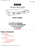
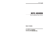
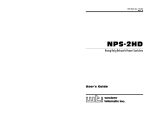
WTI Part Number: 12365
Rev. C
CAS-81
8-Port Code Activated Switch
User's Guide
5 Sterling · Irvine · California 92618
(949) 586-9950 · Toll Free: 1-800-854-7226
Fax: (949) 583-9514 · http://www.wti.com
Table of Contents
1.
In tro duc tion . . . . . . . . . . . . . . . . . . . . . . . . . . . . . . . . . . . . . . . . . . . . . 1-1
2.
Unit De scrip tion . . . . . . . . . . . . . . . . . . . . . . . . . . . . . . . . . . . . . . . . . . 2-1
2.1. Front Panel In di ca tors . . . . . . . . . . . . . . . . . . . . . . . . . . . . . . . . . . . . 2-1
2.2. Back Panel . . . . . . . . . . . . . . . . . . . . . . . . . . . . . . . . . . . . . . . . . . 2-2
3.
In stal la tion . . . . . . . . . . . . . . . . . . . . . . . . . . . . . . . .
3.1. Set DIP Switches . . . . . . . . . . . . . . . . . . . . . . . . . .
3.1.1. Data Rate (Baud) Se lec tion (Switches 1 through 3) .
3.1.2. Ti me out Se lec tion (Switches 4 and 5) . . . . . . . . .
3.1.3. Quiet Mode (Switch 6) . . . . . . . . . . . . . . . . . .
3.1.4. Auto Con nect Se rial Port 1 (Switch 7) . . . . . . . . .
3.1.5. Broad cast Mode (Switch 8) . . . . . . . . . . . . . . .
3.1.6. Force CTS (Switch 9) . . . . . . . . . . . . . . . . . .
3.1.7. Force DCD (Switch 10) . . . . . . . . . . . . . . . . .
3.2. Con nect Power Ca ble . . . . . . . . . . . . . . . . . . . . . . .
3.3. Con nect De vices to Se rial Ports . . . . . . . . . . . . . . . . .
3.4. Con nect Con trol Port. . . . . . . . . . . . . . . . . . . . . . . .
3.5. RS422 Line Driver Op tion . . . . . . . . . . . . . . . . . . . .
.
.
.
.
.
.
.
.
.
.
.
.
.
.
.
.
.
.
.
.
.
.
.
.
.
.
.
.
.
.
.
.
.
.
.
.
.
.
.
.
.
.
.
.
.
.
.
.
.
.
.
.
.
.
.
.
.
.
.
.
.
.
.
.
.
.
.
.
.
.
.
.
.
.
.
.
.
.
.
.
.
.
.
.
.
.
.
.
.
.
.
.
.
.
.
.
.
.
.
.
.
.
.
.
.
.
.
.
.
.
.
.
.
.
.
.
.
.
.
.
.
.
.
.
.
.
.
.
.
.
.
.
.
.
.
.
.
.
.
.
.
.
.
.
.
.
.
.
.
.
.
.
.
.
.
.
.
.
.
.
.
.
.
.
.
.
.
.
.
3-1
3-1
3-1
3-1
3-1
3-2
3-2
3-2
3-2
3-3
3-3
3-3
3-3
4.
Op era tion . . . . . . . . . . . . .
4.1. Power Up . . . . . . . . . .
4.2. AS CII Char ac ters . . . . . .
4.3. Com mand String . . . . . .
4.4. Com mand Re sponse . . . .
4.5. Port Gat ing . . . . . . . . .
4.5.1. Open Port Gat ing .
4.5.2. Close Port Gat ing .
.
.
.
.
.
.
.
.
4-1
4-1
4-1
4-1
4-2
4-2
4-2
4-2
.
.
.
.
.
.
.
.
.
.
.
.
.
.
.
.
.
.
.
.
.
.
.
.
.
.
.
.
.
.
.
.
.
.
.
.
.
.
.
.
.
.
.
.
.
.
.
.
.
.
.
.
.
.
.
.
.
.
.
.
.
.
.
.
.
.
.
.
.
.
.
.
.
.
.
.
.
.
.
.
.
.
.
.
.
.
.
.
.
.
.
.
.
.
.
.
.
.
.
.
.
.
.
.
.
.
.
.
.
.
.
.
.
.
.
.
.
.
.
.
.
.
.
.
.
.
.
.
.
.
.
.
.
.
.
.
.
.
.
.
.
.
.
.
.
.
.
.
.
.
.
.
.
.
.
.
.
.
.
.
.
.
.
.
.
.
.
.
.
.
.
.
.
.
.
.
.
.
.
.
.
.
.
.
.
.
.
.
.
.
.
.
.
.
.
.
.
.
.
.
.
.
.
.
.
.
.
.
.
.
.
.
.
.
.
.
.
.
.
.
.
.
.
.
.
.
.
.
.
.
.
.
.
.
.
.
.
.
.
.
.
.
.
.
.
.
.
.
.
.
.
.
.
.
.
.
A.
De scrip tion of Sys tem In ter faces . . . . .
A.1. Con trol Port (DB25 Fe male) . . . . .
A.2. Se rial Ports 1 through 8 (DB9 Male) .
A.2.1. RS422 Line Driver Op tion . .
.
.
.
.
.
.
.
.
.
.
.
.
.
.
.
.
.
.
.
.
.
.
.
.
.
.
.
.
.
.
.
.
.
.
.
.
.
.
.
.
.
.
.
.
.
.
.
.
.
.
.
.
.
.
.
.
.
.
.
.
.
.
.
.
.
.
.
.
.
.
.
.
.
.
.
.
.
.
.
.
.
.
.
.
.
.
.
.
.
.
.
.
.
.
.
.
.
.
.
.
Apx-1
Apx-1
Apx-2
Apx-2
B.
Speci fi ca tions . . . . . . . . . . . . . . . . . . . . . . . . . . . . . . . . . . . . . . . . . . Apx-3
C.
FCC No tice . . . . . . . . . . . . . . . . . . . . . . . . . . . . . . . . . . . . . . . . . . . . Apx-3
D.
Cus tomer Serv ice . . . . . . . . . . . . . . . . . . . . . . . . . . . . . . . . . . . . . . . . Apx-4
Ap pen di ces
List of Figures
2.1.
2.2.
A.1.
A.2.
Front Panel Indicators . . . . . . .
Back Panel . . . . . . . . . . . . . .
Control Port / Serial Port Interface
RS422 Option Interface . . . . . . .
.
.
.
.
.
.
.
.
.
.
.
.
.
.
.
.
.
.
.
.
.
.
.
.
.
.
.
.
.
.
.
.
.
.
.
.
.
.
.
.
.
.
.
.
.
.
.
.
.
.
.
.
.
.
.
.
.
.
.
.
.
.
.
.
.
.
.
.
.
.
.
.
.
.
.
.
.
.
.
.
.
.
.
.
.
.
.
.
.
.
.
.
.
.
.
.
.
.
.
.
.
.
.
.
.
.
.
.
.
.
.
.
.
.
.
.
. . 2-1
. . 2-2
Apx-1
Apx-2
2
1.
Introduction
The CAS-81 Code Activated Switch brings the convenience of code-based RS232 switching to
sites with multiple terminals, printers, and peripherals. The CAS-81 enables a single RS232
Control Port to switch between 8 devices via an ASCII code sequence.
Code based switching lets you control the CAS-81 from your PC or mainframe. When a
modem is attached to the Control Port, the CAS-81 can also be managed from a remote
location. Devices can be connected or disconnected by sending commands from a remote PC
via modem.
The CAS-81 can operate at speeds up to 115,000 bps and passes data in "real-time" with no
delays. Binary and graphics files can be safely passed due to the unique 8 character switch
instruction, which considerably reduces the chances of false switching.
A broadcast mode makes it easy to mass-address a group of printers, display devices, or an
array of laboratory instruments by directing the data on the Control Port to all Serial Ports
simultaneously. The broadcast mode may be selected by code or permanently selected by the
Select Switch.
An Auto-connect feature allows the Control Port to automatically connect to Serial Port 1 each
time the unit is powered up, or after a timeout or disconnect. This provides a data path to a
critical device in case of a power failure, or convenient connection to commonly used
equipment.
Each Serial Port may be configured for a balanced RS422 long distance line driver by simply
removing the socketed RS232 driver chip and plugging in an optional RS422 module. When
the module is installed, an LED on the back panel indicates the port is RS422.
Applications
· Industrial Robotic and Numeric Control
· Remote Diagnostics
· Laboratory Equipment Polling
· Data Acquisition
· Network Management
Typographic Conventions
Throughout the manual, typefaces and characters have been used to denote the following:
^ (e.g. ^X)
Indicates a key combination that is used to invoke a command.
For example, the text "^X" (Control X) indicates that the [Ctrl] key and
the [X] key should be pressed simultaneously.
COURIER FONT
Indicates characters typed on the keyboard.
For example, ^VS or ^C#.
1-1
2.
Unit Description
Figure 2.1: Front Panel Indicators
2.1. Front Panel Indicators
À
ON: Indicates power to the unit is ON.
Á
RDY: Indicates unit is Ready to operate. A steady blink indicates that the CAS-81 is
operating normally.
Â
TXD: Indicates that data is being received at Control Port pin 2.
Ã
RXD: Indicates that data is being transmitted out Control Port pin 3. Also indicates that
data is being received by pin 2 of a selected Serial Port.
Ä
RTS: Indicates that the "Request to Send" signal is present at Control Port pin 4.
Å
CTS: Indicates that the "Clear to Send" signal is present at Control Port pin 5. Also
indicates that the "Clear to Send" signal is present at pin 8 of a connected Serial Port.
Always high when all ports are disconnected.
Æ
DTR: Indicates that the "Data Terminal Ready" signal is present at Control Port pin 20.
Ç
DCD: Indicates that the "Data Carrier Detect" signal is present at Control Port pin 8.
Also indicates that the "Data Carrier Detect" signal is present at pin 1 of a connected
Serial Port. Always high when all ports are disconnected.
È
Serial Ports 1 - 8: Indicates that the corresponding numbered Serial Port is currently
connected.
2-1
CAS-81 Code Activated Switch, User's Guide
Unit Description
Figure 2.2: Back Panel
2.2. Back Panel
À
Serial Ports 1 - 8: Eight RS232 DB9 male connectors configured as DTE. Accepts a
standard AT 9 pin to printer or modem cable, depending on the application. Refer to
Appendix A for more information on the Serial Port Interface.
Note that when the RS422 Line Driver Option has been installed, an LED indicator will
be present in the blank above the Serial Port. This LED indicates that the port is
configured for RS422 communication.
Á
Control Port: RS232 DB25 female connector configured for DCE. Accepts a standard
PC to Modem Cable.
The CAS-81 will respond to proper ASCII code strings received by the Control Port.
Once a port is selected, data will pass between the Control Port and the selected Serial
Port. Refer to Appendix A for more information on the Control Port interface.
Â
Default Switch: An 8 position DIP switch that is used to select the Control Port Data
Rate, No-data timeout period, and the Auto connect and broadcast features. This switch
is read upon power up.
Ã
AC Power: Standard AC power cord receptacle and ON/OFF switch.
2-2
3.
Installation
3.1. Set DIP Switches
The DIP Switches located on the CAS-81 back panel are used to set the Data Rate, Timeout
Selection, Quiet Mode, Broadcast Mode, and other features. Note that a label on the underside
of the CAS-81 unit also describes DIP Switch settings.
3.1.1. Data Rate (Baud) Selection (Switches 1 through 3)
Select the Baud Rate for the Control Port. The Baud Rate must match that of the control
device. The CAS-81 is transparent to parity and will operate at 7 bits even or odd parity, and
at 8 bits no parity.
1
Switch
2
3
Down
Up
Down
Up
Down
Up
Down
Up
Down
Down
Up
Up
Down
Down
Up
Up
Down
Down
Down
Down
Up
Up
Up
Up
Baud Rate
1200
2400
4800
9600
19.2K
38.4K
57.6K
115K
3.1.2. Timeout Selection (Switches 4 and 5)
Selects the No-Data-Activity disconnect period. If data has not been received by the Control
Port for the specified time period, the selected Serial Port will close.
Switch
4
Down
Up
Down
Up
5
Down
Down
Up
Up
Timeout Selection
Off
5 Seconds
30 Seconds
60 Seconds
3.1.3. Quiet Mode (Switch 6)
When enabled, the CAS-81 will not respond with "Connect/Disconnect" messages.
Switch 6
Up
Down
Quiet Mode
Enable
Disable
3-1
CAS-81 Code Activated Switch, User's Guide
Installation
3.1.4. Auto Connect Serial Port 1 (Switch 7)
When enabled, automatically connects the Control Port to Serial Port 1 on the following
conditions:
1. Power Up
2. After a Timeout disconnect, if selected.
3. After a Code sequence disconnect.
Switch 7
Up
Down
Auto Connect Serial Port 1
Enable
Disable
3.1.5. Broadcast Mode (Switch 8)
When enabled, permanently activates the Broadcast Mode. Data from the Control Port will be
sent out all eight Serial Ports. Note that when the Broadcast Mode is active, all Serial Port
Status LEDs will be lit.
Data received by the selected Serial Ports will be "ord" and passed out the Control Port. If
data is received by two ports simultaneously, data output may be garbled.
A broadcast one/all jumper located on the circuit board will block received data from Serial
Ports 2 - 8. This feature allows the Control Port to receive a response message from just one
device when broadcasting commands. Receiving data from multiple devices simultaneously
may cause garbled data.
Switch 8
Up
Down
Broadcast Mode
Enable
Disable
3.1.6. Force CTS (Switch 9)
When enabled, forces the Control Port CTS pin to high.
Switch 9
Down
Up
Force CTS High
Enable
Disable
3.1.7. Force DCD (Switch 10)
When enabled, forces the Control Port DCD pin to high.
Switch 10 Force DCD High
Down
Enable
Up
Disable
3-2
CAS-81 Code Activated Switch, User's Guide
Installation
3.2. Connect Power Cable
Make certain that the CAS-81 power switch is set in the OFF position and then connect the
power cable to the AC Power connector. Connect the other end of the power cable to a
grounded AC wall outlet.
3.3. Connect Devices to Serial Ports
Serial Ports 1 - 8 are wired as standard AT 9 pin COM Ports. Connect data cables from the
desired devices to Serial Ports 1 through 8. The Serial Ports accept AT 9 pin to printer or
modem cables, depending on the application.
Caution:
Make certain that all data cables are compatible with the CAS-81 Serial Port
interface. Please refer to Appendix A for a description of the Serial Port
interface.
3.4. Connect Control Port
The Control Port is configured to appear as a 25 pin DCE modem and accepts a standard PC to
Modem straight wired cable. Use a "Null Modem Cable" to connect a modem to the Control
Port. For a description of the Control Port Interface, please refer to Appendix A.
3.5. RS422 Line Driver Option
Each Serial Port may be configured with an optional RS422 balanced line driver. These long
distance line drivers can extend high speed transmission distance to 4,000 feet using 2 twisted
pair wiring. Only the TXD and RXD signals are transmitted. The DCD and CTS signals are
set to high.
To install the optional RS422 module, simply remove the RS232 Driver chip located on the
circuit board adjacent to the desired Serial Port’s connector and plug in the RS422 module. An
LED viewed from the back panel will indicate that the port is RS422. Please refer to
Appendix A for a description of the RS422 Serial Port interface.
3-3
4.
Operation
4.1. Power Up
The ON LED indicates that AC Power has been turned on. The RDY LED indicates that the
processor is operating and the unit is READY to operate. A flickering RDY LED indicates an
AC Power brown out condition. The Control Port Status LEDs indicate the signal status of the
Control Port. The Serial Port LEDs indicate the port(s) selected. When all Serial Port LEDs
are lit, this indicates that CAS-81's Broadcast Mode is active.
Upon power-up, the unit is programmed according to the parameters selected by the setup DIP
switches, which are located next to the Control Port. (Refer to switch setup section). If you
change any of the DIP Switch settings while the unit is powered on, you must turn power off
and on to reread the switch.
4.2. ASCII Characters
The PC or controlling device connected to the Control Port must send ASCII characters at the
same data rate as the CAS-81. The unit accepts 8 bits / no parity, or 7 bits / even parity.
4.3. Command String
The command string consists of seven contiguous characters. The first 6 characters are ASCII
Control codes, and the seventh is the configuration code.
^V^X^X^V^X^Xn (Command String)
Where:
n=0
n=1-8
n=9
Disconnects
Selects Serial Port Number 1 through 8
Enables Broadcast Mode (Select All Serial Ports)
Note that if "n" equals any character other than 0 through 9, the command will be terminated.
Examples:
To select port 3, send the following command:
^V^X^X^V^X^X3
To disconnect, send the following command:
^V^X^X^V^X^X0
4-1
CAS-81 Code Activated Switch, User's Guide
Operation
4.4. Command Response
Upon receiving a valid command string, the CAS-81 will send an acknowledgment message out
the Control Port. The message is sent as 8 bits / no parity. Acknowledgment messages are as
follows:
Connected <CR>/<LF>
Disconnected <CR>/<LF>
Broadcast <CR>/<LF>
Note that the Command Response can be disabled by placing DIP Switch 6 in the UP position
to enable the Quiet Mode feature. When the Quiet Mode is active, the unit will not send
acknowledgment messages.
4.5. Port Gating
With all ports closed, data received by the Control Port will not be passed to any of the Serial
Ports. Any data received by the Serial Ports will not be passed to the Control Port. The CTS
and DCD signals will always be set high.
4.5.1. Open Port Gating
Upon receiving a valid command string at data rates up to 19,200 bps, the selected Serial Port
will open during the stop bit time of the configuration code thus allowing the next character to
be passed out the selected port.
For data rates above 19,200 bps it is necessary to delay approximately 1 millisecond before
sending data out the selected Serial Port. This prevents a character that immediately follows
the configuration character from being "cut in half".
4.5.2. Close Port Gating
Selected Serial Ports can be closed using three methods:
1. By using the Command String to select another Serial Port.
2. By Using the Command String to disconnect.
3. By using the No-Data-Activity timeout feature.
In methods 1 and 2, the Command String Control Codes will be passed out the selected Serial
Port. The Serial Port(s) will close immediately after the sixth character, thus blocking the next
character from being sent. If the configuration character was 1 - 8, then the selected Serial
Port would open. If the configuration character was 0 then the ports would remain closed.
The No-Data-Activity timeout feature can be used to make a "clean" close if the Command
String Control Codes cause a conflict with the connected devices. The Serial Port will
automatically close if no data is received from the Control Port for the time period selected by
the setup switch.
4-2
A. Description of System Interfaces
A.1. Control Port (DB25 Female)
The Control Port is a 25 pin female connector wired in a DCE (modem) configuration.
*
Not
Connected Connected
Pin
Signal
I/O
2
RXD
Input
-
To Serial Port Pin 3
3
TXD
Output
Low
Follows Serial Port
4
RTS
Input
-
To Serial Port Pin 7
5
CTS
Output
High
* Follows Serial Port
6
DSR
Output
High
Always High
7
GND
8
DCD
Output
Low
* Follows Serial Port
20
DTR
Input
-
To Serial Port Pin 4
Signal Ground
May be forced high by DIP Switches 9 and 10. Always high when all Serial Ports are
connected.
Figure A.1: Control Port / Serial Port Interface
Apx-1
CAS-81 Code Activated Switch
Appendices
A.2. Serial Ports 1 through 8 (DB9 Male)
The Serial Ports are 9 pin male, wired in a DTE configuration similar to that of an A computer.
Figure A.1 and the table below describe the Serial Port interface.
Signal
I/O
1
DCD
Input
-
To Control Port Pin 8
2
RXD
Input
-
To Control Port Pin 3
3
TXD
Output
Low
Follows Control Port Pin 2
4
DTR
Output
Low
Follows Control Port Pin 20
5
GND
Follows Control Port Pin 4
6
Signal Ground
Open
7
RTS
Output
Low
8
CTS
Input
-
9
A.2.1.
Not
Connected Connected
Pin
To Control Port Pin 5
Open
RS422 Line Driver Option
Each Serial Port may be configured with an RS422 balanced line driver. These long distance
line drivers can extend high speed transmission distance to 4,000 feet using 2 twisted pair
wiring. Only the TXD and RXD signals are transmitted. The DCD and CTS signals are set to
high. Figure A.2 below describes the RS422 Serial Port interface.
Note: Handshake signals are not passed. All other pins are open.
Figure A.2: RS422 Option Interface
Apx-2
CAS-81 Code Activated Switch
B.
Appendices
Specifications
Interface:
Control Port: (1) RS232, 25 pin female, DCE configuration.
Serial Ports: (8) RS232, 9 pin male, DTE configuration.
Optional - RS422 Line Driver (TXD and RXD only)
Signals Gated: TXD, RXD, RTS, CTS, DTR, DCD
Protocol: Asynchronous ASCII, 7/8 bits, Any Parity, One Stop Bit.
Data Rate: 1200 bps to 115K bps, switch selectable
Timeout: Off, 5, 30, and 60 seconds, switch selectable
Command Sequence: Seven contiguous characters:
^V^X^X^V^X^Xn
Where:
n=0
n=1-8
n=9
Disconnects
Selects Serial Port Number
Enters Broadcast Mode (All Serial Ports Selected)
Command Response:
Connected <CR>/<LF>
Disconnected <CR>/<LF>
Broadcast <CR>/<LF>
Power: Internal Supply - 115/230 VAC, 60/50 Hz, 10 Watts
Size: 1.75" x 17.00" x 6.5" (H x W x D) - One Rack Space
Weight: 3 pounds (5 pounds shipping)
C.
FCC Notice
This equipment has been tested and found to comply with the limits for a Class A digital
device, pursuant to Part 15 of the FCC Rules. These limits are designed to provide reasonable
protection against harmful interference when the equipment is operated in a commercial
environment. This equipment generates, uses, and can radiate radio frequency energy and, if
not installed and used in accordance with the instruction manual, may cause harmful
interference to radio communications. Operation of this equipment in a residential area is
likely to cause harmful interference in which case the user will be required to correct the
interference at his own expense.
Apx-3
CAS-81 Code Activated Switch
Appendices
D. Customer Service
Customer Service hours are 8:00 AM to 5:00 PM, Pacific Time, Monday through Friday. When
calling, please be prepared to give the name and make of the unit, its serial number, and a
description of its symptoms. If the unit should need to be returned for factory repair it must be
accompanied by a Return Authorization number from Customer Service.
WTI Customer Service
5 Sterling
Irvine, California 92618
949-586-9950
Toll Free: 1-800-854-7226
Fax: 949-457-8138
e-mail: [email protected]
Trademark and Copyright Information
WTI and Western Telematic are trademarks of Western Telematic Incorporated. All other
product names mentioned in this publication are trademarks or registered trademarks of their
respective companies.
Information and descriptions contained herein are the property of Western Telematic, Inc..
Such information and descriptions may not be copied, disseminated or distributed without the
express written consent of Western Telematic, Inc..
© Copyright Western Telematic Inc., 1997, 2000
All rights reserved.
June 2000
September 1997
Part Number: 12365 Revision: C
Apx-4