1
XP-X151-1E
UTILITY
FLIGHT MANUAL
X-15-1
ADD-ON ROCKET AIRCRAFT
FOR FLIGHT SIMULATOR
Serial number: AF56-6670
(XLR-11 and XLR-99 engines)
ENGLISH VERSION 1.0
Desktop commanders are responsible for
bringing this publication to the attention of
all flight simulator enthusiasts and X-15
fans cleared for operation of subject addon rocket aircraft.
Contains full product description and specifications, installation instructions, normal
procedures and check list.
Xtreme
Prototypes
www.xtremeprototypes.com
X-15 FOR FLIGHT SIMULATOR SERIES
UTILITY
FLIGHT MANUAL
X-15-1
ADD-ON ROCKET AIRCRAFT
FOR FLIGHT SIMULATOR
THIS SIMULATION SOFTWARE
AND ACCOMPANYING USER MANUAL
ARE NEITHER FREEWARE NOR SHAREWARE
This manual is to be used only in conjunction with the Xtreme Prototypes X-15-1 add-on
rocket aircraft for Flight Simulator. It has been purchased by the end-user as part of a software package and it is subject to the terms of use specified in the enclosed end-user software
license agreement. The end-user is authorized to make or print copies of this manual for his/
her own use, in conjunction with the X-15-1 simulation software.
PLEASE DO NOT MAKE UNAUTHORIZED
COPIES OF THESE FILES
Xtreme Prototypes X-15-1 for Flight Simulator, Version 1.0 – Utility Flight Manual (English). Copyright © 2007 by Xtreme
Prototypes, Inc. The software and the present manual are protected by international copyright laws. Please do not make unauthorized copies of the software and/or its related components and documentation, including the present user manual. No part of this
document may be reproduced or redistributed in any form or by any means without the written permission of the publisher. All
images in this document are actual screenshots of the Xtreme Prototypes X-15-1, X-15-2/3 and X-15A-2 add-on rocket aircraft for
Flight Simulator, taken in the Microsoft® Flight Simulator 2004 and Flight Simulator X game environments, except where otherwise
noted. Microsoft, Microsoft Flight Simulator, Windows and DirectX are either registered trademarks or trademarks of Microsoft
Corporation. Other company or product names mentioned herein may be trademarks or registered trademarks of their respective
owners. Software features and manual contents are subject to change without notice.
Portions of this manual have been inspired or adapted from the original real-world X-15 utility flight manuals published during the
1950s and 1960s by the U.S. Air Force and North American Aviation. NASA and AFFTC photos have been used in some sections for
comparison and illustration purposes only and are the property of their respective owners as credited. Xtreme Prototypes is not affiliated with NASA, North American Aviation (Boeing), the U.S. Air Force, or any other company, entity or government organization
related to the X-15 research program. This product is neither sponsored nor endorsed by NASA.
Xtreme Prototypes X-15-1 for Flight Simulator, Version 1.0 – Utility Flight Manual
2
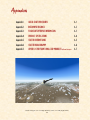
TABLE OF CONTENTS
FOREWORD
Section
Section
Section
Section
Section
Section
4
I
II
III
IV
V
VI
INTRODUCTION AND PRODUCT DESCRIPTION
1-1
SOFTWARE INSTALLATION
2-1
AIRCRAFT DESCRIPTION AND SPECIFICATIONS
3-1
INSTRUMENT PANELS
4-1
NORMAL PROCEDURES AND CHECK LIST
5-1
CONDENSED PROCEDURES AND CHECK LIST
6-1
APPENDICES
Appendix 1:
QUICK-START PROCEDURES
A-1
Appendix 2:
INSTRUMENT READINGS
A-2
Appendix 3:
FS AIRCRAFT REFERENCE INFORMATION
A-3
Appendix 4: PRODUCT SPECIFICATIONS
A-4
Appendix 5: SELECTED INTERNET LINKS
A-5
Appendix 6: SELECTED BIBLIOGRAPHY
A-6
Appendix 7: OTHER X-15 FOR FLIGHT SIMULATOR PRODUCTS by Xtreme Prototypes
A-7
Xtreme Prototypes X-15-1 for Flight Simulator, Version 1.0 – Utility Flight Manual
3
Foreword
WELCOME TO THE WORLD OF THE
X-15 FOR FLIGHT SIMULATOR!
We thank you for purchasing your copy of the
Xtreme Prototypes X-15-1 add-on rocket aircraft for Flight Simulator.
This publication contains the necessary information for the installation and operation of
the X-15-1 virtual aircraft and associated
instrument panels. It contains instructions
and procedures for both XLR-11 and XLR-99
rocket engine operation, on the X-15-1 for
Flight Simulator.
For technical and historical accuracy and in
an effort to recreate what it was like to prepare and operate the real X-15 rocket plane,
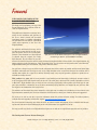
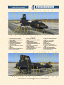
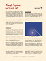
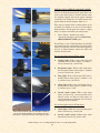
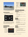
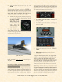
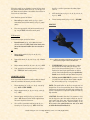
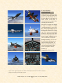
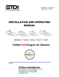
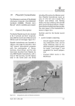
Spot plane view of the Xtreme Prototypes X-15-1 for Flight Simulator,
portions of this document have been inspired
accelerating to Mach 3. (Actual FS2004 screenshot)
or adapted from the original X-15 utility
flight manuals. We also wanted to give this
manual a look and feel from the 1950s by using presentation templates similar to those found in the original manuals. All
images appearing in this document are actual screenshots of the X-15 virtual aircraft and panels taken in the Microsoft®
Flight Simulator 2004 game environment, except where otherwise noted.
Our goal was to design a series of add-on aircraft and panels that look as realistic as possible and that would allow flight
simulation enthusiasts and X-15 fans not only to fly at high altitudes and at several times the speed of sound but also to
simulate most aspects of a typical X-15 mission, including nearly every step and procedure required to operate this remarkable and unique aircraft.
This product is a game, and we do not pretend it is one hundred percent historically or technically accurate or that it
truly reproduces all the flight characteristics of the real X-15 rocket plane, which would be virtually impossible to achieve
in Microsoft® Flight Simulator. But we tried our best to develop a high-quality add-on product that would put the computer pilot virtually in command of one of the most extraordinary flying machines ever designed by man, and have him/
her forget for one moment that this is only for fun!
The software and the manual have been designed to evolve with time, according to the feedback we receive from the vast
flight simulation community and X-15 fans around the world. Please let us know your comments, ideas and suggestions.
We invite you to visit our web site to get more information about this product and other exciting X-15 add-on products,
available fixes and upgrades, and technical support: http://www.xtremeprototypes.com
For those interested in knowing more about the real X-15 research aircraft and program, we have included some interesting Internet links and a selected bibliography at the end of this manual (see appendices 5 and 6).
We hope you will enjoy the X-15 for Flight Simulator experience as much as we enjoyed developing this series of products.
The Development Team at Xtreme Prototypes
Xtreme Prototypes X-15-1 for Flight Simulator, Version 1.0 – Utility Flight Manual
4
Introduction and
Product Description
SECTION
I
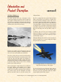
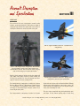
THE REAL-WORLD X-15
California desert.
The North American X-15 was a single-place rocketpowered experimental aircraft built in the late 1950s and
early 1960s for NASA (NACA), the U.S. Air Force and
the U.S. Navy to test flight at extremely high speeds and
altitudes and to obtain data on the effects of such flight
conditions on the aircraft and on the pilot.
The X-15-1, equipped with the “interim” Reaction Motors
XLR-11 rocket engines, was rolled out in October 1958,
and was transferred to Edwards Air Force Base for testing. Its first captive flight (while the X-15 is attached to
the carrier airplane) occurred in March 1959 followed by
its first glide flight in June of the same year. On January
23, 1960, the X-15-1, with NAA test pilot Scott Crossfield,
successfully completed its first powered flight attaining
Mach 2.53 and 66,844 feet with the XLR-11 rocket engines.
In February 1961, the X-15-1 was returned to North
American Aviation for conversion to its design-mission
configuration (XLR-99 engine), after completing 21 flights
with the XLR-11 engines.
NASA pilot Bill Dana flew the X-15-1 for the last time on
October 24, 1968. The No. 1 aircraft completed 81 flights
during the entire X-15 program.
The real North American X-15-1 in 1958. (NASA photo)
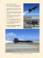
The X-15 was capable of and achieved high speed and
altitude records such as Mach 6.7 or 6629 fps (more than
twice as fast as a speeding bullet) and 354,200 feet.
Three X-15 rocket planes were built by North American
Aviation (NAA) during the X-15 research program, which
overall cost more than $300 million. The program succeeded at demonstrating the ability of pilots to fly rocketpropelled aircraft out of the earth’s atmosphere and back
to precision landing. Today, the X-15 can be considered
history’s first reusable spacecraft.
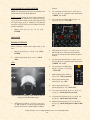
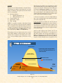
After being dropped at a high altitude from a modified B52 carrier airplane and propelled by its millionhorsepower rocket engine at several times the speed of
sound, the X-15 would fly to the edge of space, burn all its
fuel, perform reentry into the atmosphere and finally
glide its way back to land on a dry lake runway in the
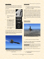
X-15-1 for Flight Simulator in her limited-mission configuration. Note the two XLR-11 rocket engines.
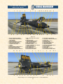
The X-15-2 aircraft arrived at Edwards in April 1959 and
made its first powered flight with the XRL-99 engine
more than a year later, in November 1960, after completing nine flights with the XLR-11 engines.
Xtreme Prototypes X-15-1 for Flight Simulator, Version 1.0 – Utility Flight Manual
1-1
In November 1962, the X-15-2 airplane was extensively
damaged during an emergency landing, after the flaps
refused to operate and the left rear landing skid failed. It
was decided to rebuild the airplane as a modified
“advanced” version of the X-15, with a longer fuselage
and external propellant tanks. The “extended performance” X-15A-2 was rolled out in February 1964.
the No. 3 aircraft. Sadly, the X-15-3 was lost in November
1967 after the airplane entered a hypersonic spin, descended in an inverted dive at almost Mach 4 and 65,000
feet and finally broke up, taking the life of Air Force pilot
Michael Adams.
Together, the three aircraft completed 199 flights during
a nine-year period, the 200th one being cancelled several
times in November and December, 1968. It was the end of
the X-15 program.
After almost 40 years, the X-15 still holds impressive
speed and altitude records. It was one of the most successful research aircraft tested at Edwards AFB.
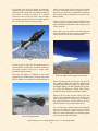
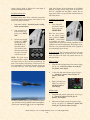
X-15A-2 for Flight Simulator. Note the external propellant
tanks.
In October 1967, Air Force pilot Pete Knight took the X15A-2 to Mach 6.7 (4520 mph), the fastest manned aircraft flight recorded to this day by a winged vehicle
(excluding the Space Shuttle).
The X-15-3 was delivered to Edwards in June 1959,
equipped with the XLR-99 engine. In August 1963, NASA
pilot Joe Walker set an altitude record of 354,200 feet in
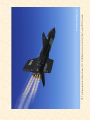
X-15-2 for Flight Simulator pulling up for her climb.
Twelve extremely skilled test pilots flew the X-15: Michael Adams (USAF), Neil Armstrong (NASA), Scott
Crossfield (NAA), Bill Dana (NASA), Joe Engle (USAF),
Pete Knight (USAF), Jack McKay (NASA), Forrest Peterson (USN), Bob Rushworth (USAF), Milt Thompson
(NASA), Joe Walker (NASA) and Bob White (USAF).
Today, the X-15-1 hangs from the ceiling in the main
gallery of the Smithsonian National Air and Space Museum in Washington, D.C. The X-15A-2 is on display at
the National Museum of the United States Air Force
(Wright-Patterson Air Force Base, Dayton, Ohio).
X-15-3 for Flight Simulator.
You can find many excellent books and publications
about the X-15 research program. Pictures and movie
clips are also available on a number of web sites. Internet
links and a selected bibliography are included in appendices 5 and 6, at the end of this manual.
Xtreme Prototypes X-15-1 for Flight Simulator, Version 1.0 – Utility Flight Manual
1-2
THE X-15 FOR FLIGHT SIMULATOR SERIES
The X-15 for Flight Simulator series of add-on rocket
aircraft brings the excitement of high-speed and highaltitude flight and the challenge of an X-15 research mission to the desktop PC.
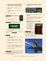
X-15-1 for Flight Simulator with the XLR-11 engines and
the NACA “vane-type” boom nose. This is the limitedmission configuration.
It consists of 11 fully detailed versions of the legendary
North American X-15 experimental rocket plane, available in three separate add-on packages (see appendix 7):
Package A contains: 4 versions of the X-15-1 airplane (s/n. AF56-6670);
Package B contains: 2 versions of the X-15-2 airplane (s/n. AF56-6671) together with 2 versions of
the X-15-3 airplane (s/n. AF56-6672);
Package C contains: 3 versions of the “advanced”
X-15A-2 airplane (s/n. AF56-6671).
Each aircraft comes with fully functional instrument
panels that allow the desktop pilot not only to fly the
airplane, but also to recreate and simulate nearly every
step and procedure required in a typical X-15 mission.
Contrary to the real-world X-15 that was launched at a
high altitude from a carrier airplane, the X-15 for Flight
Simulator can take off from an airport runway like any
other Flight Simulator aircraft! The flight model allows
the airplane to accelerate up to approximately Mach 4.65
(or the maximum speed supported in Flight Simulator
2004), reach an altitude of 100,000 feet (the actual
FS2004 limit), burn most of its fuel, complete its ballistic
The X-15 for Flight Simulator series of add-on aircraft.
trajectory, decelerate, jettison its remaining propellants
and finally glide its way back to the nearest dry lake runway or airport.
Xtreme Prototypes X-15-1 for Flight Simulator, Version 1.0 – Utility Flight Manual
1-3
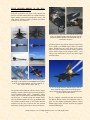
FULLY DETAILED MODELS OF THE REALWORLD X-15 ROCKET PLANE
Each add-on aircraft in the series is fully detailed and
has been carefully modeled based on available drawings,
flight manuals, government photographs, movies and
other archive material in order to conform as closely as
possible to the real-world X-15.
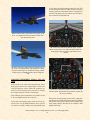
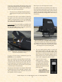
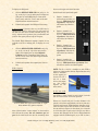
Astronaut/pilot in full-pressure suit inside the cockpit of the
X-15-1 for Flight Simulator. Note the ejection seat. The
cockpit also features detailed instrument panels and animated sticks and levers.
All aircraft feature more than 20 animated visual effects
such as XLR-11 and XLR-99 engine flame and contrail
effects, XLR-99 first and second stage igniter effects,
APU and engine turbopump exhaust effects, propellant
jettison effects, engine precool and prime effects, and a
fuselage frost effect/texture (around the liquid oxygen
tank when filled).
The images on the left are NASA or AFFTC photographs.
The images on the right are actual FS2004 screen captures
of the X-15 for Flight Simulator. From top to bottom: X15-1, X-15-2, X-15-3 and X-15A-2.
The airplanes feature different reflective textures, unique
markings, movable control surfaces (horizontal stabilizer,
vertical stabilizer/rudder with a “jettisonable” ventral
section, flaps and speed brakes), extendable landing skids
and front gear, a movable canopy with cockpit details,
pilot and animated sticks and levers, an animated eyelid
and external propellant tanks on the X-15A-2. Selected
airplanes may also carry a tail-cone box with research
instruments, wing-tip pods and/or a vane-type boom nose.
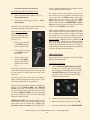
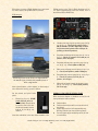
X-15-1 for Flight Simulator (XLR-99 engine). Note the
flames inside the engine nozzle (second stage igniter
effect) and the flow of liquid oxygen and ammonia coming out of the rear prime drains.
The No. 1 airplane is available with both the twin Reaction Motors XLR-11 interim four-chambered rocket engines and the mighty 60,000-pound Reaction Motors
XLR-99 rocket engine. All other airplanes are equipped
with the XLR-99 engine.
Xtreme Prototypes X-15-1 for Flight Simulator, Version 1.0 – Utility Flight Manual
1-4
on the original analog instrument found in the real X-15
aircraft during the 1950s and 1960s.Virtually all gauges,
switches, lights and instruments found on each panel are
functional and behave like the original ones described in
the real-world X-15 flight manuals.
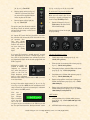
Reaction Motors XLR-11 liquid-fuel rocket engines on the
X-15-1 for Flight Simulator. Note that the number 2 engine has been shut down.
The X-15-1 instrument panels (XLR-99 engine, original
“black” version) feature over 200 animated and fully functional gauges, flight instruments, light indicators and
switches.
The million-horsepower Reaction Motors XLR-99 engine on
the X-15-1 for Flight Simulator. The XLR-99 was a liquidfuel turbo-rocket engine of variable-thrust design capable
of delivering up to 60,000 pounds of thrust at high altitude.
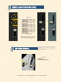
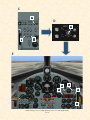
ADVANCED INSTRUMENT PANELS AND SYSTEMS
Each aircraft in the series comes with different instrument panels, either in their original black version or the
later light blue-gray version. Special (X-15-specific) systems have been integrated into each panel to simulate
the complex operation of the X-15 rocket plane.
Three different panel configurations are available for the
X-15-1 for Flight Simulator (see section IV).
Nearly 300 custom gauges (and systems) have been produced for the X-15 for Flight Simulator series, and each
one has been carefully designed and programmed based
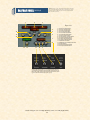
A closer view of the electrical section on the X-15-1 main
instrument panel. Note the APU and generator switches and
the AC bus voltmeters.
Each add-on aircraft package comes with a comprehensive, illustrated and fully detailed user manual (printable
PDF format), inspired and adapted from the original X-15
utility flight manuals. Each manual is available in both
English and French.
Xtreme Prototypes X-15-1 for Flight Simulator, Version 1.0 – Utility Flight Manual
1-5
Software
Installation
The X-15-1 for Flight Simulator is an add-on software
package which requires Microsoft® Flight Simulator
2004 (FS2004) to be installed on your computer in order
to function. Make sure FS2004 has been properly installed according to the instructions provided by the
manufacturer before you proceed.
SECTION
II
Special visual effects such as rocket engine flames and
exhaust contrails might reduce your frame rate on slower
processors and video cards (especially with the X-15-1
with the XLR-11 engines installed). Adjust your Flight
Simulator display parameters to correct this problem if
necessary.
Consult the documentation included with Microsoft®
Flight Simulator 2004 for information about minimum
system requirements and how to optimize your display
settings.
If you need additional support, please visit our web site:
www.xtremeprototypes.com
MINIMUM SYSTEM REQUIREMENTS
X-15-1 for Flight Simulator (rollout version), sporting the
NACA “vane-type” boom nose.
Flight Simulator: FS2004, FSX
Windows®: 2000/XP (128 MB RAM)
Processor: 450 MHz
Hard Drive: 1.8 GB
Available Disk Space: 200 MB (space required to install the add-on software)
Video Card: 32 MB (DirectX® 9.0 or later)
Other: Sound card and speakers, joystick, Adobe® Acrobat® Reader 5.0 or later
UTILITY FLIGHT MANUAL AND FSX SUPPLEMENT
COMPATIBILITY
The X-15 for Flight Simulator series of add-on rocket
aircraft has been designed and optimized for Microsoft®
Flight Simulator 2004. The product has not been extensively tested in FS2002 but may work as well.
This software version is compatible with Microsoft®
Flight Simulator X but has not been optimized for this
platform (refer to the enclosed FSX flight manual supplement for information on the installation and use of the X15 add-on aircraft in FSX). Check our web site regularly
for fixes, patches and upgrades.
As a rule of thumb, if Microsoft® Flight Simulator 2004
runs properly on your computer, you should be able to fly
the X-15 for Flight Simulator without problems.
Included with the software are the English and French
versions of the present X-15-1 Utility Flight Manual
(X-15-1_manual_eng_01.pdf) and FSX supplement (X15-1_fsx_supplement_eng_01.pdf), both available in a
printable PDF format (Adobe® Acrobat® Reader 5.0 or
later required).
To download Acrobat® Reader, visit: http://www.acrobatreader-ib.com
The flight manual contains the necessary information for
the installation and operation of the X-15-1 virtual aircraft and associated instrument panels. It contains instructions and procedures for both XLR-11 and XLR-99
Xtreme Prototypes X-15-1 for Flight Simulator, Version 1.0 – Utility Flight Manual
2-1
(XLR-99) black panel;
“Dirty” version with the NACA/
Nortronics ball nose, wing-tip pods,
tail-cone box and the (XLR-99) light
blue-gray panel.
rocket engine operation, on the X-15-1 for Flight Simulator.
The end-user is authorized and encouraged to print copies of the manual and of the supplement for his/her own
use, in conjunction with the enclosed add-on simulation
software. The best way to keep the manual handy for
easy reference during flight is to organize it in a durable
presentation binder.
PACKAGE DESCRIPTION
The installation disk (or the downloaded package) contains the following:
A “read me” file (readme.txt) that contains
the present installation instructions and other
important information.
A copy of the end-user license agreement
(eula.rtf).
English and French versions of the present
utility flight manual and of the FSX supplement in a printable PDF format.
A self-executable Setup program file (X-151_setup.exe) that is launched automatically
when the disk is inserted into your computer
disk drive. This program can also be launched
manually by double-clicking the Setup icon in
the disk folder.
If you have downloaded the software, the manuals
and the documentation are included in the Setup
program file.
The Setup program file contains the necessary software
components to be installed on your computer:
1.
The X-15-1 aircraft and panels:
2 versions of the X-15-1 aircraft (s/n AF56-6670) with the XLR-11 rocket engines:
“Clean” rollout version with the NACA
vane-type boom nose and the original
(XLR-11) black panel;
“Dirty” version with the NACA vanetype boom nose and the original (XLR11) black panel.
2 versions of the X-15-1 aircraft (s/n AF56-6670) with the XLR-99 rocket engine:
“Dirty” version with the NACA/
Nortronics ball nose and the original
2.
A cabinet (.cab) file that contains all the gauges,
switches, lights, instruments and systems for
the X-15-1 advanced panels.
3.
All the special visual effects for the X-15-1 aircraft (e.g.: rocket engine flame effects, propellant
jettison effects, APU and engine turbopump exhaust
effects, etc.).
Note that there is no custom sound package included with the software at this time. The current
version of the X-15 for Flight Simulator uses the default
FS2004 aircraft sounds. Check our web site regularly for
fixes, patches and upgrades.
AUTOMATIC INSTALLATION
Refer to the following instructions for installation in
Flight Simulator 2004. Refer to the separate FSX supplement (X-15-1_fsx_supplement_eng_01.pdf) for installation
in Flight Simulator X.
The X-15-1 for Flight Simulator is installed like any
other add-on aircraft in your default “Flight Simulator 9”
folder.
DOWNLOAD
If you have downloaded the software, simply run
the Setup program (X-15-1_setup.exe) and follow
the instructions that appear on screen. Enter your
product registration key when asked. You must accept
the end-user license agreement and enter a valid registration key before you can install and use this product. If
FSX is also installed on your computer, select if you want
the X-15-1 add-on aircraft to be installed in FS2004, FSX
or both. The installation program will then copy the necessary files into their default locations in the “Flight
Simulator 9” and/or “Microsoft Flight Simulator X” folder
(s) on your computer.
CD-ROM
If you have purchased the CD-ROM package, insert
the enclosed disc into your CD-ROM drive and follow the instructions that appear on screen. Enter
your product registration key when asked. You must ac-
Xtreme Prototypes X-15-1 for Flight Simulator, Version 1.0 – Utility Flight Manual
2-2
cept the end-user software license agreement and enter a
valid registration key before you can install and use this
product. If FSX is also installed on your computer, select
if you want the X-15-1 add-on aircraft to be installed in
FS2004, FSX or both. The installation program will then
copy the necessary files into their default locations in the
“Flight Simulator 9” and/or “Microsoft Flight Simulator
X” folder(s) on your computer.
(If your computer does not support automatic installation, click Start on the Windows® taskbar and select
Control Panel. Double-click the Add/Remove Programs icon and click Add New Programs. Follow the
instructions that appear on screen.)
Once the add-on aircraft are installed, they will be available on the Select Aircraft page in Flight Simulator.
Figure 2-1
COPYRIGHT NOTICE
The X-15 for Flight Simulator is neither freeware
nor shareware and is subject to the terms of use
specified in the enclosed end-user software license
agreement.
Note that the X-15-1 Utility Flight Manual and FSX supplement are copied by default in the “C:\Program
Files\Xtreme Prototypes\X-15-1 Documentation” folder
for your convenience and future reference. There are
available in the “Start\Programs\Xtreme Prototypes” section of the Windows® taskbar.
The software and the present manual are protected by
international copyright laws. The end-user is authorized
to print copies of the present manual for his/her own use,
in conjunction with the enclosed add-on simulation software. Please do not make unauthorized copies of the software and/or its related components and documentation,
including the present user manual.
FILE STRUCTURE
The X-15 aircraft and panels are installed in your “Flight
Simulator 9\Aircraft” folder, under different names.
Each aircraft and associated components are contained in
a different folder. The X-15 gauge cabinet is installed in
your “Flight Simulator 9\Gauges” folder. Similarly, the
X-15 special effects are installed in your “Flight Simulator 9\Effects” folder.
Adobe and Adobe Acrobat Reader are either registered trademarks or
trademarks of Adobe Systems Incorporated.
Your file structure should look like the one in Figure 2-1,
depending on the add-on aircraft purchased.
Xtreme Prototypes X-15-1 for Flight Simulator, Version 1.0 – Utility Flight Manual
2-3
Aircraft Description
and Specifications
SECTION
III
AIRPLANE
The real-world X-15 was a single-place research rocket
airplane, specifically designed to obtain data on flight at
extremely high altitudes and speeds and on the effects of
such flight conditions on the aircraft and on the pilot.
XLR-11 engines installed on the X-15-1 (limited-mission
configuration).
X-15-1 in her design-mission configuration. Note the ball
nose, the ballistic control system rockets and the open
speed brakes at the rear. This aircraft also carries wing-tip
pods covered with gray and green thermopaint.
Built by North American Aviation in the late 1950s and
early 1960s, under public contract by NACA (NASA), the
U.S. Air Force and the U.S. Navy, the airplane was developed and tested in two basic configurations.
The limited-mission configuration included two interim
Reaction Motors XLR-11 (“Experimental Liquid Rocket11”), 5900-pound four-chambered turbo-rocket engines
and either a conventional flight reference system or an
inertial flight data system.
The design-mission configuration included an inertial
XLR-99 engine installed on the X-15-1 (design-mission
configuration). Note the open speed brakes.
flight reference system and one Reaction Motors XLR-99,
60,000-pound liquid-propellant turbo-rocket engine. All
other systems and components for each airplane configuration were essentially the same.
The 25½ degree swept back wing had hydraulically operated flaps on the inboard trailing edge of each wing
Xtreme Prototypes X-15-1 for Flight Simulator, Version 1.0 – Utility Flight Manual
3-1
panel. All aerodynamic control surfaces were actuated by
irreversible hydraulic systems.
The horizontal stabilizer had a 15-degree cathedral. The
left and right sections moved simultaneously for pitch
control, differentially for roll control, and in compound
for pitch-roll control.
The upper and lower vertical stabilizers (rudders) were in
two sections; a movable outer span for yaw control and a
fixed section adjacent to the fuselage. The lower movable
section (ventral) was “jettisonable” for landing. Each
fixed section incorporated a split-flap speed brake.
X-15-1 (XLR-11 engines). Note the frost on the fuselage,
around the liquid oxygen tank, and the flow of propellants
coming out of the rear jettison ports.
For changes in airplane attitude at altitudes where aerodynamic controls are relatively ineffective, the airplane
incorporated a ballistic control system, wherein the release of gas (hydrogen peroxide) through small rockets in
the nose and wing caused the airplane to move about
each axis as required.
Propellants for the rocket engine(s) and associated turbopump(s) – water-alcohol (XLR-11 engines) or anhydrous ammonia (XLR-99 engine), liquid oxygen and hydrogen peroxide – were carried internally.
Engine pneumatic control systems and propellant tanks
were pressurized either by helium or nitrogen gas. The
airplane pressurization and air conditioning systems used
liquid nitrogen and helium.
Two auxiliary power units (APUs) drove the airplane
hydraulic pumps and AC electrical generators. They used
hydrogen peroxide as a monopropellant.
The X-15 landing gear consisted of a dual wheel nose
gear and two main (rear) landing skids. The gear was
lowered in flight by gravity and air loads.
The real-world X-15 was not designed for normal ground
takeoff but was air-launched by a modified B-52 bomber.
Unlike the original airplane, the X-15 for Flight Simulator can actually take off from the ground, like any other
Flight Simulator aircraft!
X-15-1 (XLR-99 engine) at Edwards AFB. Note the dual
wheel front gear and the two rear landing skids. The blue
NASA insignia on the front side and some other markings
have burned off during a high-speed flight and reentry
into the earth’s atmosphere.
AIRPLANE DIMENSIONS
The overall dimensions of the airplane (in-flight configuration, with gear up and ventral retained) were as follows:
Length (with boom nose and XLR-11 engines):
56 feet, 1½ inches.
Length (with boom nose and XLR-99 engine):
55 feet, 2½ inches.
Length (with ball nose and XLR-11 engines):
50 feet, 1 inch.
Length (with ball nose and XLR-99 engine): 49
feet, 2 inches.
Span: 22 feet, 4 inches.
Xtreme Prototypes X-15-1 for Flight Simulator, Version 1.0 – Utility Flight Manual
3-2
Height: 13 feet, 1 inch.
Highest altitude with the XLR-11 engines:
136,500 feet (August 12, 1960; pilot: Bob White).
NOTE: In the landing configuration (landing gross
weight and gear down, with specified nose tire and strut
inflation and with ventral jettisoned), height was 11 feet,
6 inches.
Highest Mach number with the XLR-99 engine:
Mach 6.06 (December 5, 1963; pilot: Robert Rushworth).
AIRPLANE GROSS WEIGHT
Highest speed with the XLR-99 engine: 4104
mph (June 27, 1962; pilot: Joe Walker).
The approximate launch gross weight of the airplane
(including full internal load and pilot) was approximately
32,900 pounds. However, this could vary a few hundred
pounds, depending on the engine configuration and on
the type of instrumentation carried.
Gross weight: 32,900 lbs.
Highest altitude with the XLR-99 engine:
266,500 feet (October 14, 1965; pilot: Robert Rushworth).
*: The last attempt to fly the X-15-1 was on December 20,
1968 (flight No. 200, cancelled due to bad weather). It
was the end of the X-15 program.
Landing gross weight: 12,095 lbs.
Empty weight: 11,374 lbs.
AIRPLANE SERIAL NUMBER
The U.S. Air Force serial number for the X-15 airplane
covered by this manual is AF56-6670 (X-15-1).
HISTORICAL DATA (X-15-1)
Rollout: October 15, 1958 (arrived at Edwards Air
Force Base two days later).
First captive flight: March 10, 1959.
X-15-1 (limited-mission configuration) in flight.
First glide flight: June 8, 1959.
First powered flight (XLR-11 engines): January
23, 1960 (pilot: Scott Crossfield).
Conversion to XLR-99 engine: February, 1961.
Last flight: October 24, 1968* (pilot: Bill Dana).
Number of flights: 81 (21 with the XLR-11 engines).
Highest Mach number with the XLR-11 engines: Mach 3.31 (August 4, 1960; pilot: Joe
Walker).
Highest speed with the XLR-11 engines: 2196
mph (August 4, 1960; pilot: Joe Walker).
X-15-1 (design-mission configuration) in flight.
Xtreme Prototypes X-15-1 for Flight Simulator, Version 1.0 – Utility Flight Manual
3-3
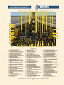
GENERAL ARRANGEMENT
X-15-1 (BOOM NOSE, XLR-11 ENGINES,
“CLEAN” ROLLOUT VERSION)
1
2
13
3
14
4
15
5
16
17
6
7
18
8
19
9
20
10
21
11
12
22
Figure 3-1
1. MOVABLE HORIZONTAL STABILIZER
2. BALLISTIC CONTROL SYSTEM ROCKETS (2,
ON BOTH WINGS)
3. UPPER SPEED BRAKE
4. MOVABLE UPPER VERTICAL STABILIZER
5. LIQUID OXYGEN TANK (FROST)
6. APU EXHAUST (2, LEFT AND RIGHT)
7. UPPER UHF ANTENNA
8. TOP BUG-EYE CAMERA PORT (2, ON BOTH
SIDES)
9. CANOPY
10. PITOT HEAD
11. BALLISTIC CONTROL SYSTEM ROCKETS (8)
12. NACA VANE-TYPE BOOM NOSE
23
29
30
24
31
3
32 33
13. WING (2, LEFT AND RIGHT)
14. REAR LANDING GEAR SKID (2, ON BOTH
SIDES)
15. LOWER SPEED BRAKE
16. LOWER FIXED VERTICAL STABILIZER
(MOVABLE VENTRAL REMOVED)
17. VENTRAL BUG-EYE CAMERA PORT (2, ON
BOTH SIDES)
18. SIDE FAIRING (2, LEFT AND RIGHT)
19. LOWER UHF ANTENNA
20. EXTERNAL CANOPY EMERGENCY JETTISON
HANDLE ACCESS DOOR
21. NOSE LANDING GEAR DOOR
22. NOSE LANDING GEAR
4
15
1
13
14
16
18
5
34
2
23. UPPER XLR-11 ENGINE TURBOPUMP EXHAUST
24. UPPER XLR-11 ROCKET ENGINE
25. EQUIPMENT COMPARTMENT
26. EJECTION SEAT
27. PILOT
28. INSTRUMENT PANEL
29. LIQUID OXYGEN JETTISON PORT
30. LOWER XLR-11 ENGINE TURBOPUMP EXHAUST
31. LOWER XLR-11 ROCKET ENGINE
32. WATER-ALCOHOL JETTISON PORT
33. HYDROGEN PEROXIDE JETTISON PORT
34. FLAP (2, LEFT AND RIGHT)
7
17
8
25
26
19
9
27
28 11
21
22
12
Xtreme Prototypes X-15-1 for Flight Simulator Version 1.0 – Utility Flight Manual
3-4
GENERAL ARRANGEMENT
X-15-1 (BALL NOSE, XLR-99 ENGINE,
WING-TIP PODS VERSION)
1
12
13
2
3
14
4
15
16
5
18
17
7
6
19
38
27
35
8
20
28
21
36
37
9 10
22
11
23
Figure 3-2
1. MOVABLE HORIZONTAL STABILIZER
2. BALLISTIC CONTROL SYSTEM ROCKETS (2,
ON BOTH WINGS)
3. UPPER SPEED BRAKE
4. MOVABLE UPPER VERTICAL STABILIZER
5. LIQUID OXYGEN TANK (FROST)
6. APU EXHAUST (2, LEFT AND RIGHT)
7. EQUIPMENT COMPARTMENT
8. CANOPY
9. PITOT HEAD
10. BALLISTIC CONTROL SYSTEM ROCKETS (8)
11. NACA/NORTRONICS BALL NOSE
12. WING-TIP POD (2, LEFT AND RIGHT)
13. GRAY/GREEN THERMOPAINT ON WING TIP
24
30
25
31
14. REAR LANDING GEAR SKID (2, ON BOTH
SIDES)
15. LOWER SPEED BRAKE
16. LOWER FIXED VERTICAL STABILIZER
(MOVABLE VENTRAL REMOVED)
17. WING (2, LEFT AND RIGHT)
18. SIDE FAIRING (2, LEFT AND RIGHT)
19. LOWER UHF ANTENNAS
20. EXTERNAL CANOPY EMERGENCY JETTISON
HANDLE ACCESS DOOR
21. NOSE LANDING GEAR DOOR
22. NOSE LANDING GEAR
23. GRAY THERMOPAINT ON NOSE
24. ENGINE TURBOPUMP EXHAUST
26
3
4
32
33
15
1
14
17
16
5
18
12
34
25. TAIL-CONE BOX CIRCULAR DOOR
26. TAIL-CONE BOX (RESEARCH INSTRUMENTS)
27. EJECTION SEAT
28. PILOT (FULL PRESSURE SUIT)
29. INSTRUMENT PANEL
30. LIQUID OXYGEN JETTISON PORT
31. XLR-99 ROCKET ENGINE
32. AMMONIA JETTISON PORT
33. HYDROGEN PEROXIDE JETTISON PORT
34. FLAP (2, LEFT AND RIGHT)
35. COCKPIT CAMERA
36. COCKPIT LIGHT
37. ENGINE TIMER (STOPWATCH)
38. RECONNAISSANCE CAMERA WINDOW
6
7
19
8
28
21
Xtreme Prototypes X-15-1 for Flight Simulator Version 1.0 – Utility Flight Manual
3-5
22
29
10
11
Instrument
Panels
SECTION
IV
figurations are available for the X-15-1. Included with
each X-15-1 add-on aircraft is:
1.
2.
3.
4.
5.
6.
7.
8.
9.
A main panel;
A service panel;
A “vent, pressurize, jettison” lever panel;
A throttle and speed brake lever panel;
A left side panel;
A right side panel;
A radio and ADF panel;
A center pedestal panel;
A SAS/RAS panel (on some aircraft).
In addition, the default FS2004 Garmin GPS and magnetic compass panels are available to the desktop pilot.
What makes the X-15 for Flight Simulator exciting and
unique are the fully functional instrument panels that
have been designed for the desktop pilot to simulate almost every step and procedure required during a typical
X-15 mission. For example:
Aircraft servicing (all three propellants and gases);
APUs/generators/hydraulic pump operation;
Propellant tank pressurization;
Engine precool and prime;
Turbopump operation;
Rocket ignition sequence;
Monitoring of propellant pressure gauges;
Propellant jettison.
Almost every X-15 internal system has been integrated
into the X-15 for Flight Simulator panels:
Engine propellant and control system;
Engine ignition system;
APUs and electrical power distribution systems;
Hydraulic system;
Temperature control systems.
(Note that the cabin air conditioning and pressurization
system is not fully functional in this software version.)
Each X-15 for Flight Simulator add-on aircraft comes
with one main instrument panel and at least seven secondary panels, either in their original black version or the
later light blue-gray version. Three different panel con-
Virtually all gauges, switches, light indicators and instruments on the panels are functional and behave like the
original analog devices described in the real-world X-15
flight manuals. Over 240 custom gauges have been developed for the X-15-1 for Flight Simulator.
X-15 instrument panels are complex. In order for the
desktop pilot to familiarize him/herself with the many
different panels, special “tooltips” or captions have been
integrated within every gauge, switch, light and instrument. Simply move the cursor over a gauge and its name
will appear under it. Therefore, each panel can be used as
a learning tool for understanding the different panel configurations and the complex operation of the X-15 rocket
planes.
An interesting aspect of the X-15 for Flight Simulator is
that because the aircraft systems and panels have been
designed according to their real-world counterparts, the
original X-15 flight manuals can also be used by experienced desktop pilots, along with the software, to go
through the check lists and procedures, just as the X-15
test pilots were accustomed to doing back in the 1960s.
To fully cover the description and operation of the X-15
internal systems and individual gauges and instruments
is beyond the scope of this manual. Interested desktop
pilots will find this information in reproductions of the
original X-15 utility flight manuals, available today in
book form or on the Internet (see appendices 5 and 6).
Xtreme Prototypes X-15-1 for Flight Simulator, Version 1.0 – Utility Flight Manual
4-1
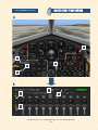
WITH CONVENTIONAL FLIGHT REFERENCE
SYSTEM AND XLR-11 ENGINES (X-15-1a, b)
MAIN PANEL
* Gauges in gray do not perform any specific simulator function.
15 16 17 18 19
20
21 22 23 24
25
26 27 28 29 30 31 32 33 34 35 36 37 38 39
40
41
42
14
13
12
11
10
9
8
43
44
45
7
6
5
4
46
3 2 1
81 80 79 78 77 76 75 74 73 72 71 70 69 68 67 66 65 64 63 62 61 60 59 58 57 56 55 54
53 52 51 50
49
48
47
Figure 4-1
1.
2.
3.
4.
5.
6.
7.
8.
9.
WATER-ALCOHOL JETTISON STOP SWITCH
H2O2 JETTISON STOP SWITCH
LIQUID OXYGEN JETTISON STOP SWITCH
DISPLAY/HIDE LEFT WHITE CONSOLE ICON
DISPLAY/HIDE LEFT SIDE PANEL ICON
HELIUM SOURCE PRESSURE GAUGE
AUXILIARY LAUNCH SWITCH*
LANDING GEAR HANDLE
DISPLAY/HIDE ICONS: RADIO/ADF PANEL, ATC
WINDOW, GPS, COMPASS, MAP, KNEEBOARD
10. VENTRAL JETTISON BUTTON
11. ENGINE MASTER SWITCH
12. UPPER ENGINE PRIME SWITCH
13. UPPER ENGINE GAS GENERATOR PREHEAT
INDICATOR LIGHT
14. LOWER ENGINE GAS GENERATOR PREHEAT
INDICATOR LIGHT
15. TANK SHUTOFF AND N2 BLEED SWITCH
16. NITROGEN RELEASE SELECTOR SWITCH
17. ENGINE COMP’T FIRE-WARNING LIGHT
18. LOWER ENGINE PRIME SWITCH
19. ALTIMETER
20. AIRSPEED INDICATOR
21. FUEL QUANTITY GAUGE
22. ACCELEROMETER
23. ANGLE-OF-ATTACK INDICATOR
24. ATTITUDE INDICATOR
25. SIDESLIP INDICATOR
26. NO. 1 APU SWITCH
27. PITCH ANGLE SET CONTROL
28. LOW-ALTITUDE MACHMETER
29. HIGH-ALTITUDE MACHMETER
30. NO. 1 APU H2O2 OVERHEAT WARNING LIGHT
31. NO. 1 APU COMPARTMENT OVERHEAT
CAUTION LIGHT
32. NO. 1 GENERATOR-OUT LIGHT
33. NO. 1 GENERATOR AC VOLTMETER
34. VERTICAL VELOCITY INDICATOR
35. NO. 1 GENERATOR SWITCH
36. NO. 2 GENERATOR SWITCH
37. EMERGENCY BATTERY SWITCH
38. DISPLAY/HIDE SERVICE PANEL ICON
39. NO. 2 GENERATOR-OUT LIGHT
40. NO. 2 GENERATOR AC VOLTMETER
41. NO. 2 APU H2O2 OVERHEAT WARNING LIGHT
42. NO. 2 APU COMPARTMENT OVERHEAT
CAUTION LIGHT
43. NO. 2 APU H2O2-LOW CAUTION LIGHT
44. NO. 2 APU SWITCH
45. CANOPY INTERNAL EMERGENCY JETTISON
HANDLE
46. DISPLAY/HIDE RIGHT SIDE PANEL ICON
47. READY-TO-LAUNCH SWITCH
48. STABLE PLATFORM SWITCH
49. NO. 2 HYDRAULIC TEMPERATURE GAUGE
50. CABIN PRESSURE ALTIMETER
51. HYDRAULIC PRESSURE GAUGE
52. CABIN HELIUM SOURCE PRESSURE GAUGE
53. NO. 2 BALLISTIC CONTROL SWITCH
54. APU BEARING TEMPERATURE GAUGE
55. APU HYDROGEN PEROXIDE PRESSURE GAUGE
56. NO. 1 BALLISTIC CONTROL SWITCH
57. MIXING CHAMBER TEMPERATURE GAUGE
58. APU HELIUM PRESSURE GAUGE
59. NO. 1 APU H2O2-LOW CAUTION LIGHT
60. NO. 1 HYDRAULIC TEMPERATURE GAUGE
61. CLOCK
62. DISPLAY/HIDE CENTER PEDESTAL ICON
63. COURSE INDICATOR (ADF INDICATOR)
64. RATE-OF-ROLL INDICATOR
65. UPPER ENGINE THRUST CHAMBER PRESSURE
GAUGE
66. LOWER ENGINE THRUST CHAMBER PRESSURE
GAUGE
67. UPPER ENGINE OVERSPEED RESET BUTTON
68. LOWER ENGINE OVERSPEED RESET BUTTON
69. LOWER ENGINE OVERSPEED CAUTION LIGHT
70. UPPER ENGINE OVERSPEED CAUTION LIGHT
71. GOVERNOR BALANCE LINE PRESS. GAUGE
72. LOWER ENGINE THRUST CHAMBER PRESSURE
GAUGE
73. UPPER ENGINE THRUST CHAMBER PRESSURE
GAUGE
74. NITROGEN LINE CONTROL AND BLEED
PRESSURE GAUGE
75. LOWER ENG. MANIFOLD PRESSURE GAUGE
76. UPPER ENG. MANIFOLD PRESSURE GAUGE
77. H2O2 COMPARTMENT-HOT CAUTION LIGHT
78. NITROGEN LINE TANK AND CONTROL
PRESSURE GAUGE
79. LIQUID OXYGEN AND WATER-ALCOHOL LINE
PRESSURE GAUGE
80. DISPLAY/HIDE THROTTLE AND SPEED BRAKE
PANEL ICON
81. NITROGEN SOURCE PRESSURE GAUGE
Xtreme Prototypes X-15-1 for Flight Simulator, Version 1.0 – Utility Flight Manual
4-2
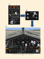
MAIN PANEL
WITH INERTIAL ALL-ATTITUDE FLIGHT
DATA SYSTEM AND XLR-99 ENGINE (X-15-1c)
* Gauges in gray do not perform any specific simulator function.
24 25
26 27
28 29 30 31 32 33
34
35 36 37 38 39 40 41 42 43 44 45 46 47 48
49
23
22
21
20
50
19
18
17
16
15
14
13
12
11
10
9
8
7
6
5
4
51
52
53
54
89
55
3 2 1
88 87 86 85 84 83 82 81
80 79 78 77 76 75 74 73 72 71 70 69 68 67 66 65 64 63 62 61 60 59
58
57 56
Figure 4-2
1.
2.
3.
4.
5.
6.
7.
8.
9.
10.
11.
12.
13.
14.
15.
16.
17.
18.
19.
20.
21.
22.
23.
24.
25.
26.
27.
28.
29.
30.
AMMONIA JETTISON STOP SWITCH
H2O2 JETTISON STOP SWITCH
LIQUID OXYGEN JETTISON STOP SWITCH
H2O2 SOURCE AND PURGE PRESSURE GAUGE
DISPLAY/HIDE LEFT SIDE PANEL ICON
PROPELLANT TANK PRESSURE GAUGE
AUXILIARY LAUNCH SWITCH*
PROPELLANT PUMP INLET PRESSURE GAUGE
LANDING GEAR HANDLE
HELIUM RELEASE SELECTOR SWITCH
VENTRAL JETTISON BUTTON
PROPELLANT SOURCE PRESSURE GAUGE
FIRE-WARNING LIGHT
AMMONIA TANK PRESSURE-LOW CAUTION
LIGHT
ENGINE VIB MALFUNCTION CAUTION LIGHT
PROPELLANT EMERGENCY PRESS SWITCH
TURBOPUMP OVERSPEED CAUTION LIGHT
LIQUID OXYGEN PRESSURE-LOW CAUTION
LIGHT
STAGE 2 IGN. MALFUNCTION CAUTION LIGHT
VALVE MALFUNCTION CAUTION LIGHT
IDLE-END CAUTION LIGHT
NO-DROP OR 23-SECOND CAUTION LIGHT
IGNITION-READY LIGHT
DISPLAY/HIDE LEFT WHITE CONSOLE ICON
DISPLAY/HIDE THROTTLE AND SPEED BRAKE
PANEL ICON
ALTIMETER
AIRSPEED/MACH INDICATOR
PILOT’S OXYGEN-LOW CAUTION LIGHT
FUEL QUANTITY GAUGE
ACCELEROMETER
31.
32.
33.
34.
35.
36.
37.
38.
39.
40.
41.
42.
43.
44.
45.
46.
47.
48.
49.
50.
51.
52.
53.
54.
55.
56.
57.
58.
59.
ANGLE-OF-ATTACK INDICATOR
ATTITUDE INDICATOR
AZIMUTH/ADF INDICATOR
ENGINE TIMER (STOPWATCH)
NO. 1 APU SWITCH
PITCH ANGLE SET CONTROL
INERTIAL SPEED (VELOCITY) INDICATOR
INERTIAL HEIGH (ALTIMETER) INDICATOR
NO.1 APU H2O2 COMPARTMENT OVERHEAT
WARNING LIGHT
NO. 1 APU COMPARTMENT OVERHEAT CAUTION LIGHT
NO.1 GENERATOR-OUT LIGHT
RAS-OUT CAUTION LIGHT
NO. 1 GENERATOR AC VOLTMETER
VERTICAL VELOCITY INDICATOR
NO.1 GENERATOR SWITCH
NO. 2 GENERATOR SWITCH
EMERGENCY BATTERY SWITCH
NO. 2 GENERATOR-OUT LIGHT
HYDROGEN PEROXIDE TRANSFER SWITCH
NO.2 GENERATOR AC VOLTMETER
NO. 2 APU H2O2 COMPARTMENT OVERHEAT
WARNING LIGHT
NO. 2 APU COMPARTMENT OVERHEAT CAUTION LIGHT
NO. 2 APU H2O2-LOW CAUTION LIGHT
NO.2 APU SWITCH
CANOPY INT. EMERGENCY JETTISON HANDLE
DISPLAY/HIDE RIGHT PANEL ICON
STABLE PLATFORM SWITCH
NO. 2 HYDRAULIC TEMPERATURE GAUGE
CABIN PRESSURE ALTIMETER
60.
61.
62.
63.
64.
65.
66.
67.
68.
69.
70.
71.
72.
73.
74.
75.
76.
77.
78.
79.
80.
81.
82.
83.
84.
85.
86.
87.
88.
89.
HYDRAULIC PRESSURE GAUGE
CABIN HELIUM SOURCE PRESSURE GAUGE
NO. 2 BALLISTIC CONTROL SWITCH
APU BEARING TEMPERATURE GAUGE
APU H2O2 TANK PRESSURE GAUGE
NO. 1 BALLISTIC CONTROL SWITCH
MIXING CHAMBER TEMPERATURE GAUGE
APU SOURCE PRESSURE GAUGE
NO.1 APU H2O2-LOW CAUTION LIGHT
NO.1 HYDRAULIC TEMPERATURE GAUGE
CLOCK
DISPLAY/HIDE CENTRAL PEDESTAL ICON
LIQUID OXYGEN BEARING TEMPERATURE
GAUGE
RATE-OF-ROLL INDICATOR
IGNITER IDLE SWITCH
H2O2 COMPARTMENT-HOT CAUTION LIGHT
CHAMBER & STAGE 2 IGNITER PRESS. GAUGE
TURBOPUMP IDLE BUTTON
ENGINE PRIME SWITCH
DISPLAY/HIDE ICONS: RADIO/ADF PANEL,
ATC WINDOW, GPS
DISPLAY/HIDE ICONS: COMPASS, MAP
ENGINE PRECOOL SWITCH
READY-TO-LAUNCH SWITCH
DISPLAY/HIDE KNEEBOARD ICON
PROPELLANT MANIFOLD PRESSURE GAUGE
FUEL LINE-LOW CAUTION LIGHT
H2O2 TANK AND ENGINE CONTROL LINE
PRESSURE GAUGE
ENGINE RESET BUTTON
ENGINE MASTER SWITCH
DISPLAY/HIDE SERVICE PANEL ICON
Xtreme Prototypes X-15-1 for Flight Simulator, Version 1.0 – Utility Flight Manual
4-3
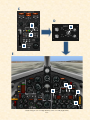
MAIN PANEL
WITH INERTIAL ALL-ATTITUDE FLIGHT
DATA SYSTEM AND XLR-99 ENGINE (X-15-1d)
* Gauges in gray do not perform any specific simulator function.
23 24
25 26
27 28 29 30 31 32
33
34 35 36 37 38 39 40 41 42 43 44 45 46 47
48
22
21
20
19
49
50
18
17
16
51
52
53
15
14
13
12
11
10
9
8
7
6
5
4
54
55
56
3 2 1
83 82 81 80 79 78 77 76 75 74 73 72 71
70
69
68 67 66 65 64 63 62 61 60
59
58 57
Figure 4-3
1.
2.
3.
4.
5.
6.
7.
8.
9.
10.
11.
12.
13.
14.
15.
16.
17.
18.
19.
20.
21.
22.
23.
24.
25.
26.
27.
28.
AMMONIA JETTISON STOP SWITCH
H2O2 JETTISON STOP SWITCH
LIQUID OXYGEN JETTISON STOP SWITCH
H2O2 SOURCE AND PURGE PRESSURE GAUGE
AUXILIARY LAUNCH SWITCH*
ENGINE MASTER SWITCH
DISPLAY/HIDE LEFT SIDE PANEL ICON
ENGINE RESET BUTTON
LANDING GEAR HANDLE
AMMONIA TANK PRESSURE-LOW CAUTION
LIGHT
VENTRAL JETTISON BUTTON
PROPELLANT EMERGENCY PRESS SWITCH
PROPELLANT SOURCE PRESSURE GAUGE
LIQUID OXYGEN PRESSURE-LOW CAUTION
LIGHT
ENGINE VIB MALFUNCTION CAUTION LIGHT
TURBOPUMP OVERSPEED CAUTION LIGHT
HELIUM RELEASE SELECTOR SWITCH
STAGE 2 IGNITION MALFUNCTION CAUTION
LIGHT
VALVE MALFUNCTION CAUTION LIGHT
IDLE-END CAUTION LIGHT
NO-DROP OR 23-SECOND CAUTION LIGHT
IGNITION-READY LIGHT
DISPLAY/HIDE LEFT WHITE CONSOLE ICON
DISPLAY/HIDE THROTTLE AND SPEED BRAKE
PANEL ICON
ALTIMETER
AIRSPEED/MACH INDICATOR
PILOT’S OXYGEN-LOW CAUTION LIGHT
CHAMBER AND STAGE 2 IGNITER PRESSURE
29.
30.
31.
32.
33.
34.
35.
36.
37.
38.
39.
40.
41.
42.
43.
44.
45.
46.
47.
48.
49.
50.
51.
52.
53.
54.
55.
56.
GAUGE
ACCELEROMETER
ANGLE-OF-ATTACK INDICATOR
ATTITUDE INDICATOR
DYNAMIC PRESSURE INDICATOR
ENGINE TIMER (STOPWATCH)
FIRE-WARNING LIGHT
SIDESLIP SELECTOR SWITCH
HYDRAULIC PRESSURE GAUGE
INERTIAL SPEED (VELOCITY) INDICATOR
INERTIAL HEIGH (ALTIMETER) INDICATOR
PITCH ANGLE SET CONTROL
NO. 1 BALLISTIC CONTROL SWITCH
DISPLAY/HIDE SERVICE PANEL ICON
NO.1 GENERATOR-OUT LIGHT
VERTICAL VELOCITY INDICATOR
NO.1 GENERATOR SWITCH
GENERATOR AC VOLTMETER
EMERGENCY BATTERY SWITCH
NO. 2 GENERATOR-OUT LIGHT
HYDROGEN PEROXIDE TRANSFER SWITCH
NO. 2 GENERATOR SWITCH
NO. 2 BALLISTIC CONTROL SWITCH
NO.1 APU H2O2 COMPARTMENT OVERHEAT
WARNING LIGHT
NO. 2 APU H2O2 COMPARTMENT OVERHEAT
WARNING LIGHT
NO. 2 APU COMPARTMENT OVERHEAT CAUTION LIGHT
NO.2 APU SWITCH
NO. 2 APU H2O2-LOW CAUTION LIGHT
CANOPY INT. EMERGENCY JETTISON HANDLE
57.
58.
59.
60.
61.
62.
63.
64.
65.
66.
67.
68.
69.
70.
71.
72.
73.
74.
75.
76.
77.
78.
79.
80.
81.
82.
83.
DISPLAY/HIDE RIGHT PANEL ICON
STABLE PLATFORM SWITCH
CABIN HELIUM SOURCE PRESSURE GAUGE
CABIN PRESSURE ALTIMETER
MIXING CHAMBER TEMPERATURE GAUGE
APU BEARING TEMPERATURE GAUGE
NO.1 APU H2O2-LOW CAUTION LIGHT
NO. 1 APU COMPARTMENT OVERHEAT CAUTION LIGHT
APU SOURCE PRESSURE GAUGE
APU H2O2 TANK PRESSURE GAUGE
NO. 1 APU SWITCH
DISPLAY/HIDE ICONS: RADIO PANEL, ATC
WINDOW, GPS, COMPASS, MAP, KNEEBOARD
RATE-OF-ROLL INDICATOR
SAS/RAS PANEL (SEE FIGURE 4-13)
DISPLAY/HIDE CENTRAL PEDESTAL ICON
PROPELLANT MANIFOLD PRESSURE GAUGE
CLOCK
PROPELLANT PUMP INLET PRESSURE GAUGE
IGNITER IDLE SWITCH
READY-TO-LAUNCH SWITCH
FUEL LINE-LOW CAUTION LIGHT
TURBOPUMP IDLE BUTTON
H2O2 TANK AND ENGINE CONTROL LINE
PRESSURE GAUGE
ENGINE PRIME SWITCH
PROPELLANT TANK PRESSURE GAUGE
ENGINE PRECOOL SWITCH
H2O2 COMPARTMENT-HOT CAUTION LIGHT
Xtreme Prototypes X-15-1 for Flight Simulator, Version 1.0 – Utility Flight Manual
4-4
SERVICE PANEL
1
2
3
4
5
6
7
8
9
10
11
27
12
26
13
25
24
23
22
21
20
19
18
17
16
15
14
Figure 4-4
1. LIQUID OXYGEN TANK VOLUME GAUGE
2. WATER-ALCOOL (OR AMMONIA) TANK VOLUME GAUGE
3. TURBOPUMP HYDROGEN PEROXIDE TANK
VOLUME GAUGE
4. PROPELLANT SOURCE TANK (HELIUM) PRESSURE GAUGE
5. ENGINE & PROPELLANT CONTROL SOURCE
TANK (NITROGEN OR HELIUM) PRESSURE
GAUGE
6. EXPRESS FILL BUTTON
7. ENGINE PURGE & EMERGENCY SOURCE TANKS
(NITROGEN OR HELIUM) PRESSURE GAUGE
8. UNLIMITED FUEL OPTION SWITCH
9. APU PROPELLANT SOURCE TANKS (HELIUM)
PRESSURE GAUGE
10. APU HYDROGEN PEROXIDE TANKS VOLUME
GAUGE
11. B-52 CARRIER X-15 READY-TO-LAUNCH INDICATOR
12. CABIN SOURCE TANK (HELIUM) PRESSURE
GAUGE
13. LIQUID NITROGEN VOLUME GAUGE
14. LIQUID NITROGEN FEED VALVE LEVER
15. CABIN SOURCE TANK (HELIUM) FEED VALVE
LEVER
16. APU HYDROGEN PEROXIDE TANKS FEED
VALVE LEVER
17. APU PROPELLANT SOURCE TANKS (HELIUM)
FEED VALVE LEVER
18. ENGINE PURGE & EMERGENCY SOURCE TANKS
(NITROGEN OR HELIUM) FEED VALVE LEVER*
2
2
4
3
5
6
Figure 4-5
1.
2.
3.
4.
1
3
6
* NOTE: Valve levers 18 and 19 are linked together.
* NOTE: Gauges in gray are animated and behave like their
real-world counterparts but they do not perform any specific
simulator function at this time in the X-15 for Flight Simulator
series of add-on aircraft.
LEFT SIDE PANEL
1
19. ENGINE & PROPELLANT CONTROL SOURCE
TANK (NITROGEN OR HELIUM) FEED VALVE
LEVER*
20. PROPELLANT SOURCE TANK (HELIUM) FEED
VALVE LEVER
21. TURBOPUMP HYDROGEN PEROXIDE TANK
FEED VALVE LEVER
22. WATER-ALCOHOL (OR AMMONIA) TANK FEED
VALVE LEVER
23. LIQUID OXYGEN TANK FEED VALVE LEVER
24. EXTERNAL POWER SWITCH
25. EXTERNAL POWER INDICATOR LIGHT
26. SERVICE PANEL POWER SWITCH
27. SERVICE PANEL POWER INDICATOR LIGHT
LANDING GEAR HANDLE
VENTRAL JETTISON BUTTON
AUXILIARY LAUNCH SWITCH*
WATER-ALCOHOL (OR AMMONIA) JETTISON
STOP SWITCH
5. HYDROGEN PEROXIDE JETTISON STOP SWITCH
6. LIQUID OXYGEN JETTISON STOP SWITCH
4
5
Xtreme Prototypes X-15-1 for Flight Simulator, Version 1.0 – Utility Flight Manual
4-5
* NOTE: Gauges in gray are animated and behave like their
real-world counterparts but they do not perform any specific
simulator function at this time in the X-15 for Flight Simulator
series of add-on aircraft.
RIGHT SIDE PANEL
1
1
1
2
2
3
9
8
7
2
3
9
3
9
4
4
4
5
5
5
6
8
7
6
8
Figure 4-6
7
6
Figure 4-7
1. CANOPY INTERNAL EMERGENCY JETTISONHANDLE*
2. READY-TO-LAUNCH SWITCH
3. VENTRAL ARMING SWITCH
4. RIGHT WINDSHIELD HEATER SWITCH
5. LEFT WINDSHIELD HEATER SWITCH
6. FIRE-WARNING LIGHT TEST BUTTON
7. INDICATOR, CAUTION AND WARNING LIGHT
TEST SWITCH
8. COCKPIT LIGHTING SWITCH
9. STABLE PLATFORM SWITCH
1. CANOPY INTERNAL EMERGENCY JETTISON
HANDLE*
2. NOSE BALLISTIC ROCKET HEATER SWITCH
3. VENTRAL ARMING SWITCH
4. RIGHT WINDSHIELD HEATER SWITCH
5. LEFT WINDSHIELD HEATER SWITCH
6. FIRE-WARNING LIGHT TEST BUTTON
7. INDICATOR, CAUTION AND WARNING LIGHT
TEST SWITCH
8. COCKPIT LIGHTING SWITCH
9. STABLE PLATFORM SWITCH
RADIO/ADF PANEL
3
2
Figure 4-8
1
4
7
5
1.
2.
3.
4.
5.
6.
7.
MAIN CHANNEL SECLECTOR KNOB
MAIN CHANNEL INDICATOR
FUNCTION SELECTOR SWITCH
MAIN CHANNEL “VOLUME” CONTROL
AUXILLIARY CHANNEL “VOLUME” CONTROL
AUXILLIARY CHANNEL INDICATOR
AUXILLIARY CHANNEL SELECTOR KNOB
6
Xtreme Prototypes X-15-1 for Flight Simulator, Version 1.0 – Utility Flight Manual
4-6
THROTTLE AND SPEED BRAKE PANEL
1
2
3
4
5
6
7
8
9
Figure 4-9
1. UPPER XLR-11 ENGINE, CHAMBER 1 THRUST
SELECTOR SWITCH
2. UPPER XLR-11 ENGINE, CHAMBER 2 THRUST
SELECTOR SWITCH
3. UPPER XLR-11 ENGINE, CHAMBER 3 THRUST
SELECTOR SWITCH
4. UPPER XLR-11 ENGINE, CHAMBER 4 THRUST
SELECTOR SWITCH
5. LOWER XLR-11 ENGINE, CHAMBER 1 THRUST
SELECTOR SWITCH
6. LOWER XLR-11 ENGINE, CHAMBER 2 THRUST
SELECTOR SWITCH
7. LOWER XLR-11 ENGINE, CHAMBER 3 THRUST
SELECTOR SWITCH
8. LOWER XLR-11 ENGINE, CHAMBER 4 THRUST
SELECTOR SWITCH
9. UPPER AND LOWER SPEED BRAKE LEVERS
(LINKED TOGETHER)
10. XLR-99 ENGINE THROTTLE LEVER
10
9
NOTE: Chamber 1 and chamber 3 switches on each
engine are linked together. Chamber 2 and chamber
4 switches on each engine are linked together.
* NOTE: Gauges in gray are animated and behave like their
real-world counterparts but they do not perform any specific
simulator function at this time in the X-15 for Flight Simulator
series of add-on aircraft.
LEFT WHITE CONSOLE
Figure 4-10
1. FLAP SWITCH
2. JETTISON TRIM SWITCH*
3. VENT, PRESSURIZE, JETTISON LEVER
2
1
3
Xtreme Prototypes X-15-1 for Flight Simulator, Version 1.0 – Utility Flight Manual
4-7
* NOTE: Gauges in gray are animated and behave like their
real-world counterparts but they do not perform any specific
simulator function at this time in the X-15 for Flight Simulator
series of add-on aircraft.
CENTER PEDESTAL
1
2
3
4
Figure 4-11
32
5
31
6
7
30
8
9
29
10
28
27
26
11
12
13
14
25
15
16
17
18
24
23
22
21
19
1. SAS PITCH CAUTION LIGHT*
2. SAS ROLL CAUTION LIGHT
3. SAS YAR CAUTION LIGHT
4. SAS YAW CAUTION LIGHT
5. SAS YAW FUNCTION SWITCH
6. SAS YAR FUNCTION SWITCH
7. SAS TEST SWITCH
8. YAW GAIN SELECTOR KNOB*
9. BALL NOSE POWER SWITCH
10. INSTRUMENTATION MASTER POWER SWITCH
11. ENGINE OSCILLOGRAPH RECORD SWITCH
12. CALIBRATE BUTTON AND LIGHT
13. TELEMETER MASTER POWER SWITCH
14. CAMERA SWITCH
15. FM TELEMETER POWER SWITCH
16. TELEMETER COMMUTATOR MOTOR SWITCH
17. COCKPIT RAM-AIR KNOB
18. ENGINE VIBRATION RECORDER SWITCH
19. DC VOLTMETER
20. DC VOLTMETER SWITCH
21. STABLE PLATFORM INSTRUMENT SWITCH
22. RADAR BEACON POWER SWITCH
23. PHYSIOLOGICAL INSTRUMENTATION SWITCH
24. STRAIN GAUGE POWER SWITCH
25. BALL NOSE TEST BUTTON
26. DATA LIGHT
27. DATA SWITCH
28. RAM-AIR LEVER
29. SAS ROLL AND YAR GAIN SELECTOR KNOB
30. SAS PITCH GAIN SELECTOR KNOB
31. SAS ROLL FUNCTION SWITCH
32. SAS PITCH FUNCTION SWITCH
20
1
2
3
4
5
Figure 4-12
1.
2.
3.
4.
5.
6.
7.
8.
9.
10.
11.
12.
13.
14.
15.
16.
17.
18.
DATA LIGHT*
CALIBRATE BUTTON AND LIGHT
PHYSIOLOGICAL INSTRUMENTATION SWITCH
BLOOD PRESSURE SWITCH
BALL NOSE POWER SWITCH
BALL NOSE TEST BUTTON
FM TELEMETER POWER SWITCH
TAPE RECORDER POWER SWITCH
STABLE PLATFORM INSTRUMENT SWITCH
COCKPIT RAM-AIR KNOB
DC VOLTMETER
DC VOLTMETER SELECTOR SWITCH
RADAR BEACON POWER SWITCH
INSTRUMENTATION MASTER POWER SWITCH
RAM-AIR LEVER
TELEMETER MASTER POWER SWITCH
TELEMETER COMMUTATOR MOTOR SWITCH
DATA SWITCH
18
17
16
15
6
7
8
9
14
10
13
11
12
Xtreme Prototypes X-15-1 for Flight Simulator, Version 1.0 – Utility Flight Manual
4-8
* NOTE: Gauges in gray are animated and behave like their
real-world counterparts but they do not perform any specific
simulator function at this time in the X-15 for Flight Simulator
series of add-on aircraft.
SAS/RAS PANEL (X-15-1c,d)
1
2
3
Figure 4-13
4
16
5
15
6
14
7
8
13
12
11
10
1. SAS PITCH CAUTION LIGHT
2. SAS ROLL CAUTION LIGHT
3. SAS YAW CAUTION LIGHT
4. SAS YAR CAUTION LIGHT
5. SAS YAR FUNCTION SWITCH
6. SAS YAW FUNCTION SWITCH
7. RAS-OUT CAUTION LIGHT
8. RAS AUTOMATIC CUTOFF SWITCH
9. RAS YAW FUNCTION SWITCH
10. RAS ROLL FUNCTION SWITCH
11. RAS PITCH FUNCTION SWITCH
12. ALTERNATE SAS SWITCH
13. ALTERNATE SAS ON INDICATOR LIGHT
14. SAS TEST SWITCH
15. SAS PITCH FUNCTION SWITCH
16. SAS ROLL FUNCTION SWITCH
9
Separate RAS panel on the X-15-1 equipped with the XLR-99 engine and the original black instrument panels (small control box on
the left side of the cockpit in the real aircraft). The RAS-out caution
light is on the main instrument panel [42, fig. 4-2].
Xtreme Prototypes X-15-1 for Flight Simulator, Version 1.0 – Utility Flight Manual
4-9
COCKPIT CONFIGURATION (CANOPY REMOVED, TYPICAL)
1
2
3
Figure 4-14
4
18
1.
2.
3.
4.
5.
6.
7.
8.
9.
MAIN INSTRUMENT PANEL
RAM-AIR LEVER
CENTER PEDESTAL
CENTER STICK
RIGHT SIDE PANEL
CIRCUIT-BREAKER PANEL
PRESSURE COOLING LEVER
CONSOLE STICK
PILOT (DAVID CLARK A/P22S-2 FULL-PRESSURE
SUIT AND HELMET)
10. EJECTION SEAT STABILIZING FIN
11. EJECTION SEAT EJECTABLE HEADREST
12. EJECTION SEAT
13. EJECTION SEAT ARMREST
14. RADIO PANEL
15. SPEED BRAKE HANDLES
16. ENGINE THRUST SELECTOR SWITCHES (XLR-11
ENGINE) OR ENGINE THROTTLE (XLR-99 ENGINE)
17. VENT, PRESSURIZE AND JETTISON LEVER
18. LEFT SIDE PANEL
19. CANOPY INTERNAL HANDLE
20. RESTRAINT EMERGENCY RELEASE HANDLE
21. SHOULDER HARNESS
22. PARACHUTE CONTAINER
23. EJECTION HANDLE
24. RAS CONTROL PANEL (ON SOME AIRCRAFT)
25. BALLISTIC CONTROL STICK
26. OXYGEN SELECTOR AND GAUGE, FOOT RESTRAINT RELEASE BUTTON
5
6
17
16
7
15
8
14
9
13
12
19
20
11
8
10
9
11
10
6
21
9
24
25
17
16
11
7
12
21
22
1
4
10
12
22
23
26
15
Xtreme Prototypes X-15-1 for Flight Simulator, Version 1.0 – Utility Flight Manual
4-10
23
Normal Procedures
and Check List
This section contains the complete normal procedures
and check list for the operation of the X-15-1 add-on
rocket aircraft for Flight Simulator (a condensed version
of these procedures is provided in section VI). You can
also refer to appendix 1 to start the engine and fly the X15 for Flight Simulator without going through the complete check list and procedures presented here.
Aircraft reference information is provided in appendix 3.
The same information is also available in the FS aircraft
Reference information tab of the Kneeboard (F10).
SECTION
V
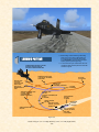
TYPICAL MISSION
In a typical and real-world X-15 mission (see fig. 5-1 on
page 5-24), the rocket airplane would be attached under
the right wing of a modified B-52 bomber (NB-52) and
carried to an altitude of about 45,000 feet. Then, at a
scheduled launch time, it would be dropped and the pilot
would ignite the airplane’s powerful rocket engine(s) to
propel the X-15 at several times the speed of sound to
high altitude and speed records.
NOTE: This section contains instructions and procedures
for both XLR-11 and XLR-99 rocket engine operation on
the X-15-1 add-on aircraft.
INTRODUCTION
In an effort to recreate the real-world X-15 experience
and for historical and technical accuracy, most of the
following procedures are inspired or adapted from the
original X-15 utility flight manuals. Following each step
presented here will allow you to recreate a typical X-15
mission in Flight Simulator and will make your overall
experience more realistic and enjoyable.
The operation of the add-on aircraft is very similar to the
operation of the real-world aircraft. Reading this section
before your first flight is highly recommended and will
help you in understanding the complex operation of this
unusual and remarkable air and space vehicle.
However, fully covering the description and operation of
each of the X-15 systems and individual gauges, light
indicators, switches and instruments is beyond the scope
of the present manual. Interested flight simulation enthusiasts can find this information in reproductions of
the original X-15 utility flight manuals, available today in
book form or on the Internet (see appendices 5 and 6).
These manuals, now in the public domain, contain complementary information to the material presented in this
section and can also be used by experienced desktop pilots, along with the X-15 add-on software, to recreate X15 flights and missions in Flight Simulator.
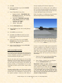
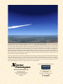
X-15-1 accelerating to Mach 4.0.
Several experiments would be conducted during the mission to get as much information as possible about highspeed and high-altitude flight and about the effects of
such flight conditions on the aircraft and on the pilot.
After the airplane propellants were exhausted or the
engine was shut down by the pilot, the X-15 would perform reentry into the atmosphere and begin a shallow
descent during its glide back to a dry lakebed in the California desert.
The X-15 for Flight Simulator can be launched either
from a high altitude like the real X-15 (saved flight) or
simply take off from an airport runway like any other
Flight Simulator aircraft. For simplicity and to allow
ground servicing of the virtual airplane, the following
procedures assume a normal takeoff from the ground.
Xtreme Prototypes X-15-1 for Flight Simulator, Version 1.0 – Utility Flight Manual
5-1
Because of the limitations of the Microsoft® Flight Simulator game environment, the maximum altitude to be
reached by any of the X-15 for Flight Simulator aircraft
in FS2004 is 100,000 feet. The maximum speed is approximately Mach 4.65.
recommended to fly the X-15 for Flight Simulator
aircraft. Pedals are optional.)
3.
Start Microsoft® Flight Simulator.
4.
Select the CREATE FLIGHT option in the menu at
left.
5.
In the “Create Flight” page, click CHANGE under
“Selected Aircraft” (1) to open the “Select Aircraft”
page.
6.
Select the following:
The procedures presented here are for a typical mission,
and do not cover any specific experimentation.
INITIAL FLIGHT SIMULATOR CONFIGURATION
For your first X-15 flight, we suggest a normal takeoff
from Rosamond airfield, California (L00), runway 07 and
a landing near Rogers Dry Lake at Edwards Air Force
Base (KEDW), runway 04. Although the real X-15 landed
on the lakebed, we will attempt to land our virtual X-15
on the base runway like a conventional FS2004 aircraft.
a.
b.
c.
We will attempt to recreate Scott Crossfield’s historical
flight No. 1-2-7 which took place on January 23, 1960
(first powered flight by the X-15-1 with the XLR-11 engines, from Rosamond Dry Lake to Rogers Dry Lake).
Aircraft Manufacturer – NORTH AMERICAN AVIATION.
Aircraft Model – X-15 ROCKET PLANE
NO. 1.
Variation – BOOM NOSE, XLR-11 ENGINES, BLACK PANEL, CLEAN ROLLOUT VERSION (or any other available version of the X-15-1, either with the XLR-11 or
XLR-99 engines, if you want to fly a different
mission).
7.
Click OK.
8.
On the “Create Flight” page, click CHANGE under
“Selected Weather” (3) to open the “Weather” page.
9.
On the “Weather” page, select USER-DEFINED
WEATHER, then click the CUSTOMIZE
WEATHER button.
10. On the “Customized Weather” page, enter the following conditions:
Flight configuration page in Microsoft FS2004.
a.
b.
c.
d.
e.
Clouds – FEW.
Precipitation – NONE.
Visibility – 40 MI / 64 KM.
Wind Speed – LIGHT (8 KTS).
Wind Direction – 70°.
11. Click OK twice.
CREATING A FLIGHT
1.
2.
Make sure the X-15 for Flight Simulator has been
properly installed in your “Flight Simulator 9”
folder according to the instructions provided in section II.
Make sure your joystick, or yoke and pedals are
properly connected to your computer and have been
previously tested in Flight Simulator. (A joystick is
12. On the “Create Flight” page, click CHANGE under
“Selected Time and Season” (4).
13. On the “Time and Season” page, set “Local Time” to:
16:17:05.
14. On the “Time and Season” page, set date to: JANUARY 23, 1960.
Xtreme Prototypes X-15-1 for Flight Simulator, Version 1.0 – Utility Flight Manual
5-2
15. Click OK.
nitrogen, depending on the aircraft configuration.
16. On the “Create Flight” page, click the FLIGHT
PLANNER button.
Concurrently, the two auxiliary power units (APUs) in
the X-15 consume hydrogen peroxide under helium pressure from separate tanks. The APUs provide both electrical power and hydraulic power to the aircraft.
17. On the “Flight Planner” page, select:
a.
b.
c.
d.
Departure location – ROSAMOND (L00),
RUNWAY 07 (Rosamond – L00, California,
United States, Runway 07).
Destination – EDWARDS AIR FORCE
BASE (KEDW) (Edwards AFB - KEDW,
California, United States).
Flight plan type – VFR.
Routing – Direct-GPS.
Finally, the airplane air conditioning and pressurization
systems use liquid nitrogen pressurized by helium.
18. Click the FIND ROUTE button.
19. On the “Find Route” page, enter: Cruising Altitude
– 60,000 feet.
20. Click SAVE to save your route.
21. Click OK. Answer YES when asked if you want
Flight Simulator to move your aircraft to the selected airport.
22. On the “Create Flight” page, click the SAVE
FLIGHT button to save your flight. Name this
flight: X-15-1 Flight No. 1-2-7.
23. On the “Create Flight” page, click the FLY NOW
button to start your flight.
FUEL MANAGEMENT SYSTEM
Conventional aircraft found in Microsoft® Flight Simulator use only one type of fuel (either aviation gasoline or
jet fuel). Propellant consumption is automatically calculated and managed by the game engine.
Like the real-world rocket airplane, the X-15 for Flight
Simulator uses at least three different types of propellants: water-alcohol or anhydrous (waterless) ammonia as
the main engine fuel, liquid oxygen as the oxidizer and
hydrogen peroxide as a monopropellant for the engine
turbopump, the APUs and the ballistic control system
rockets.
The main propellant tanks in the X-15 aircraft are pressurized with helium (nitrogen in the case of the hydrogen
peroxide tanks in the limited-mission configuration) and
the airplane’s pneumatic controls use either helium or
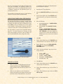
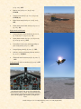
X-15-1 venting her propellant tanks. Frost and condensation from the cold propellants can be seen on the fuselage
and around the internal liquid oxygen tank. The boiling
point of liquid oxygen is –297° F in standard atmospheric
conditions.
In order to recreate these complex systems and simulate
as close as possible the true operation of the X-15 aircraft, special built-in systems have been designed and
integrated into the X-15 for Flight Simulator instrument
panels. These systems bypass the Flight Simulator fuel
management system and need some special settings in
the simulator:
1.
Under the “Aircraft” menu in the main Flight Simulator window, select REALISM SETTINGS.
2.
On the “Settings – Realism” page, under “Engines”,
select the UNLIMITED FUEL option.
IMPORTANT NOTE: The engine autostart command
in Flight Simulator (CTRL-E) is intentionally disabled in
order to simulate the true rocket engine start procedures
described herein and because of the complexity of the X15 fuel management system, servicing and engine ignition sequence. Also note that all systems are reset
when a new X-15 aircraft main instrument panel is
reloaded in Flight Simulator.
Xtreme Prototypes X-15-1 for Flight Simulator, Version 1.0 – Utility Flight Manual
5-3
SPECIAL VISUAL EFFECTS (AIRCRAFT LIGHTS)
1
2
The X-15 for Flight Simulator special visual effects such
as the rocket engine flames or the APU exhaust effects
are internally triggered with aircraft system commands
(“event IDs”). For example, the No. 2 APU exhaust effect
appears when the aircraft navigation lights are on.
There were no external lights or smoke systems on the
real-world X-15 airplane, so we can use all the available
Flight Simulator aircraft lights and systems to display
many X-15-specific visual effects (see images at left).
1.
3
4
On the “Settings – Realism” page, under
“Instruments and Lights”, select the PILOT CONTROLS AIRCRAFT LIGHT option.
The following is a list of Flight Simulator aircraft lights
and systems and their corresponding X-15 special visual
effects. Note that these effects are internally triggered by
the X-15 for Flight Simulator systems and panels and
should be off at this time.
5
6
For aircraft equipped with the XLR-11 engines:
Landing lights: XLR-11 rocket engine flame and
turbopump exhaust effects (engine 1, chambers 1
and 3), as shown in fig. 1 and 2 at left.
7
8
Recognition lights: XLR-11 rocket engine flame
and turbopump exhaust effects (engine 1, chambers
2 and 4), as shown in fig. 1 at left.
Wing lights: XLR-11 rocket engine flame and turbopump exhaust effects (engine 2, chambers 1 and
3), as shown in fig. 1 and 2 at left.
Cabin lights: XLR-11 rocket engine flame and turbopump exhaust effects (engine 2, chambers 2 and
4), as shown in fig. 1 at left.
9
10
Aircraft smoke system: XLR-11 engine prime
effects, as shown in fig. 7 at left (note that in this
software version, the effects on both engines are
triggered simultaneously although in the real-world,
each engine prime is separate).
For aircraft equipped with the XLR-99 engine:
11
12
Some of the spectacular special visual effects created for
the X-15 for Flight Simulator series of add-on aircraft.
Each effect is associated with a FS aircraft light or system.
Cabin lights: XLR-99 first and second stage igniter
effects, as shown in fig. 5 and 6 at left.
Aircraft smoke system: XLR-99 rocket engine
flame effect, as shown in fig. 3 and 4 at left.
Xtreme Prototypes X-15-1 for Flight Simulator, Version 1.0 – Utility Flight Manual
5-4
Wing lights: hydrogen peroxide jettison effect, as
shown in fig. 8 on the previous page.
Recognition lights: XLR-99 engine turbopump
exhaust effect (see page 5-22).
EXTERIOR INSPECTION
An exterior description of the X-15 for Flight Simulator is
available in section III (figure 3-1 and figure 3-2). It is
recommended to familiarize yourself with the general
external arrangement of the aircraft before proceeding.
For all X-15-1 for Flight Simulator aircraft:
Taxi lights: frost on the fuselage and condensation
vapor effect around the liquid oxygen tank when
filled, as shown in fig. 9 on the previous page.
In the real world: Because of the mission of the X-15 and
the equipment used by the pilot, it was not feasible for
him to perform an exterior inspection of the aircraft before
flight. This task was left to the ground personnel.
Strobe lights: No. 1 APU exhaust effect, as shown
in fig. 5, 8 and 9 on the previous page.
Navigation lights: No. 2 APU exhaust effect, as
shown in fig. 5, 8 and 9 on the previous page.
Beacon lights: liquid oxygen jettison effect (in addition to engine precool and prime effects on aircraft equipped with the XLR-99 engine), as shown in
fig. 5, 6, 8 and 10 on the previous page.
Logo lights: ammonia jettison effect (or wateralcohol jettison effect on aircraft equipped with the
XLR-11 engines and in addition to prime effect on
aircraft equipped with the XLR-99 engine), as
shown in fig. 5, 6, 8 and 10 on the previous page.
Tailhook: ventral jettison animation effect (see
page 5-32).
X-15-1 for Flight Simulator (clean “rollout” version).
1.
Aircraft contrail: X-15 rocket engine contrail effects, as shown in fig. 11 and 12 on the previous
page.
OTHER FLIGHT SIMULATOR SETTINGS
The other recommended settings will make your first
flight in the X-15 more enjoyable:
1.
On the “Settings – Realism” page, set the following:
a.
b.
c.
d.
e.
2.
All “Flight Model” settings – 50% (cursor in
the middle).
Gyro drift – SELECTED.
Display indicated airspeed – SELECTED.
Ignore crashes and damage – SELECTED.
G-effects – UNSELECTED.
Click OK to close the “Settings – Realism” page and
return to the game.
Select the SPOT PLANE view, either with the appropriate button on your joystick, by depressing the
“S” key on your keyboard several times, or on the
“View Options” page (under the “Views” menu in the
Flight Simulator main window, click “View Options” and select SPOT PLANE view).
This will permit you to inspect the exterior of the X-15.
You can use the appropriate button on your joystick (or
the arrow keys on your numeric keypad) to move around
the aircraft. Use the “+/=” or “_/-” keys on your keyboard
to zoom in and out.
At this time, the X-15 has not yet been serviced and the
engine(s) should be shut down. If the engine(s) has(have)
been ignited by the simulator and has(have) not been
shut down automatically by the X-15 integrated systems,
do the following procedure to shut down the engine(s):
1.
Simultaneously press the CTRL-SHIFT-F1 keys on
your keyboard.
No visual effects (associated with aircraft lights or sys-
Xtreme Prototypes X-15-1 for Flight Simulator, Version 1.0 – Utility Flight Manual
5-5
tems) such as engine flames, APU exhaust steam or frost
on the fuselage should be observed around the airplane at
this time. If such effects are visible, do the following procedure to turn off the unwanted effects:
1.
Press the “L” key (All Lights On/Off command) on
your keyboard as necessary, until the effects disappear.
Don’t forget to close the canopy before takeoff!
It is possible to observe the movement of the control surfaces, including the speed brakes, at this time. In the real
world, that would not be totally feasible without the APUs
operating and providing enough hydraulic power to the
motors (a characteristic not supported in this version of
the software).
The ventral section of the vertical stabilizer (rudder) does
not appear on the X-15 at this time to provide ground
clearance and enough space for the rear landing skids.
The ventral rudder will appear later, when the landing
gear and skids are raised after takeoff.
In the real world: The ventral rudder was installed by the
ground crew after the X-15 was lifted and attached under
the wing of the NB-52 carrier. It was later jettisoned by
the pilot before landing (see page 5-32).
Rear view of the X-15-1 showing the XLR-11 engines.
Note how both engines are slightly canted so that their
thrust vector intersects at the aircraft’s center of gravity
for stability reasons. Also, the ventral rudder does not appear on the X-15 at this time to provide ground clearance
and enough space for the rear landing skids.
1.
Use your joystick (and/or pedals) to control and
observe the movement of the upper vertical stabilizer (rudder) and of the horizontal stabilizer. Note
that there are no ailerons on the X-15. The left and
right sections of the horizontal stabilizer move simultaneously for pitch control, differentially for roll
control, and in compound for pitch-roll control.
2.
To open or close the speed
brakes, press the “ / ” key on
your keyboard. The speed brakes
can also be opened, closed and
adjusted using the speed brake
handle on the throttle and speed
brake side panel:
X-15-1 (limited-mission configuration) showing the main
instrument panel inside the cockpit.
To open or close the canopy, simultaneously press the
SHIFT-E keys on your keyboard.
Take a look inside the cockpit and observe how the movement of the center stick and of the right stick controller
corresponds to the movement of your joystick. The throttle and speed brake levers inside the cockpit behave according to the movement of the throttle on your joystick
or the movement of the speed brakes.
Note that the astronaut/pilot is wearing the David Clark
A/P22S-2 full-pressure suit and helmet, released in early
1961, an improvement over the earlier MC-2 suit used at
the beginning of the X-15 program.
a.
Click the DISPLAY/
HIDE THROTTLE AND
SPEED BRAKE PANEL
Xtreme Prototypes X-15-1 for Flight Simulator, Version 1.0 – Utility Flight Manual
5-6
b.
c.
d.
3.
icon [80, fig. 4-1; 25, fig. 4-2; 24, fig. 4-3] on
the main panel to display the throttle and
speed brake panel (or select THROTTLE
AND SPEED BRAKE PANEL from the
“Instrument Panel” menu, under the “Views”
menu of the main Flight Simulator window
menu bar).
Undock and reposition the panel if necessary. You can undock the throttle and speed
brake panel (like any other Flight Simulator
panel) from the main window by rightclicking the panel and selecting the UNDOCK WINDOW option.
Pull the speed brake lever (downward) to
open the speed brakes.
Push the speed brake lever forward
(upward) to close the speed brakes.
before flight. During captive flight (while the rocket plane
was attached to the NB-52 and gaining altitude), the X-15
liquid oxygen tank was topped off from the carrier airplane supply.
To simulate the complex servicing of the X-15 rocket
plane both from the ground or from the NB-52 carrier
airplane, a fictional “service panel” has been provided
with each X-15 for Flight Simulator aircraft. This panel
is adapted in part from the launch operator’s panel installed inside the NB-52 carrier. Refer to figure 4-4 in
section IV for a description of the X-15 for Flight Simulator service panel.
Again, if desired, click the DISPLAY/HIDE
THROTTLE AND SPEED BRAKE PANEL icon
[80, fig. 4-1; 25, fig. 4-2; 24, fig. 4-3] on the main
panel to hide the throttle and speed brake panel (or
unselect THROTTLE AND SPEED BRAKE
PANEL from the “Instrument Panel” menu, under
the “View” menu of the main Flight Simulator window menu bar).
NOTE: Like on the real-world aircraft, all X-15 for Flight
Simulator instruments and gauges use imperial measures.
Rear view of the X-15-1 showing the large split-flap upper
and lower speed brakes.
Make sure the canopy is closed (SHIFT-E on your keyboard) and return to the “Cockpit” view.
SERVICING
In the real world: Propellants and gases were loaded onto
both the NB-52 carrier and the X-15 by the ground crew
1.
Click the DISPLAY/HIDE X-15 SERVICE
PANEL icon [38, fig. 4-1; 89, fig 4-2; 41, fig 4-3] on
the right side of the main panel, to display the service panel (or select SERVICE PANEL from the
“Instrument Panel” menu, under the “Views” menu
of the main Flight Simulator window menu bar).
2.
Undock and reposition the panel if necessary.
The service panel provides electrical power to the X-15
aircraft before the APUs can be turned on. This would
simulate electrical power to be supplied
to the X-15 either from a ground receptacle or from the carrier airplane.
1.
Service panel power switch [26, fig.
4-4] – ON. This will turn on the
service panel.
2.
Service panel (green) power light
Xtreme Prototypes X-15-1 for Flight Simulator, Version 1.0 – Utility Flight Manual
5-7
3.
4.
[27, fig. 4-4] – Check ON.
[47, fig. 4-1; 82, fig. 4-2; 76, fig. 4-3] to ON.
External power switch [24, fig. 4-4]
– ON. We will assume that electrical power will be supplied from the
carrier airplane at this time.
To service the X-15, proceed as follows:
External power (yellow) light [25,
fig. 4-4] – Check ON.
The service panel also allows the individual filling of the X-15 internal propellant
and gas tanks by turning a series of control valve levers.
Make sure all control valve levers
[14-23, fig. 4-4] under each gauge are
in the (center) CLOSED position.
1.
Express fill button [6, fig. 4-4] –
Push (once). All tanks will be
filled simultaneously.
Check each gauge, from left to right,
for proper filling:
An “express fill” button has been provided to accelerate
the procedure and concurrently fill all the tanks in a single operation. Pressure
and
volume
gauges are provided to
monitor each tank at
any time during servicing and during
flight.
In a typical X-15 mission, a normal “burnout” occurred
after approximately 90 seconds of XLR-99 engine operation, after all the propellants were exhausted (run time
was significantly higher on the aircraft equipped with the
XLR-11 engines).
Although by default it is
possible to simulate this
condition, an “unlimited
fuel” switch has been provided on the X-15 for
Flight Simulator service
panel to allow unlimitedduration burns. Simply turn the switch to ON if you wish
to use this feature.
As long as the engine master switch [11, fig. 4-1; 88, fig.
4-2; 6, fig. 4-3] is set to OFF, the fuel consumption can be
reset to normal at any time by returning the “unlimited
fuel” switch to the OFF position.
Note that a
green placardtype
indicator
light is installed
at the top right
side of the service panel to give an indication to the NB-52 crew that
the X-15 pilot has turned the “Ready-to-Launch” switch
“Airplane Propellants” section:
1.
Liquid oxygen tank volume gauge [1, fig. 4-4] –
Check (1017 gallons).
2.
Water-alcohol (or ammonia) tank volume gauge [2,
fig. 4-4] – Check (1445 gallons).
3.
Turbopump hydrogen peroxide (H2O2) tank volume
gauge [3, fig. 4-4] – Check (78 gallons).
4.
Propellant source (helium) tank pressure gauge [4,
fig. 4-4] – Check (3200-3800 psi).
5.
Engine and propellant control source (nitrogen or
helium) tank pressure gauge [5, fig. 4-4] – Check
(3200-3800 psi).
6.
Engine purge and emergency source (nitrogen or
helium) tanks pressure gauge [7, fig. 4-4] – Check
(3200-3800 psi, both pointers).
“APU” section:
1.
APU propellant source (helium) tanks pressure
gauge [9, fig. 4-4] – Check (3200-3800 psi, both
pointers).
2.
APU H2O2 tanks volume gauge [10, fig. 4-4] –
Xtreme Prototypes X-15-1 for Flight Simulator, Version 1.0 – Utility Flight Manual
5-8
Check (60-75 gallons, both pointers).
switch is simply disabled and will not respond to mouse
clicks or perform any desired function.
“Air Conditioning and Pressurization” section:
1.
Cabin helium tank pressure gauge [12, fig. 4-4] –
Check (3200-3800 psi).
2.
Liquid N2 tank volume gauge [13, fig. 4-4] – Check
(25-30 gallons).
Note that the air conditioning and pressurization system
is not truly functional in this software version.
(As an alternate procedure, each
propellant or gas tank can be
controlled individually with its
associated control valve lever
[14-23, fig. 4-4]:
1.
Turn the lever to the left
in the DUMP position to
jettison contents of tank.
2.
Turn the lever to the right
in the FEED position to
fill the tank.
3.
Leave (or turn) lever at
center in the CLOSED
position to stop filling or
jettisoning and close the
valve.
For example, the service panel control valve levers cannot be turned if the “vent, pressurize and jettison” lever
[3, fig. 4-10] is not in the VENT position or if the engine
precool switch [81, fig. 4-2; 82, fig. 4-3] is set to PRECOOL. Concurrently, the “vent, pressurize and jettison”
lever can only be moved to the PRESSURIZE or JETTISON positions when all the service panel control valve
levers are in the CLOSED (center) position.
Some switches, especially the ones related to the engine
ignition sequence, behave in the same manner. If a switch
or lever simply refuses to operate normally, the desktop
pilot should revise the previous procedures and make
sure that all the required steps have been performed in
the correct order. Forgetting to fill the propellant source
(helium) tanks, for example, will prevent the propellant
tanks from being pressurized and the engine prime
switch from being activated because there is simply no
pressurized gas to allow the propellants to be pushed and
to circulate through the engine feed lines.
PREFLIGHT CHECK
Refer to section IV for a description of the X-15 for Flight
Simulator instrument panels.
Left console and side panel:
1.
Click the DISPLAY/HIDE RADIO/ADF PANEL
icon [9, fig. 4-1; 79, fig 4-2; 68, fig. 4-3] on the main
panel to display the radio/ADF panel (or select RADIO/ADF PANEL from the “Instrument Panel”
menu, under the “View” menu of the main Flight
Simulator window menu bar).
2.
Undock and reposition the panel if necessary.
3.
Radio function selector switch [3, fig. 4-8] – OFF.
4.
If not already displayed, click the DISPLAY/HIDE
The tanks will be topped off automatically to prevent
overfill. Each tank can be monitored at any time by reading the pressure or volume gauge above each control
valve lever.
Note that two valve levers [18-19, fig. 4-4] are linked together for filling purposes even though they are associated with separate helium or nitrogen tanks.)
After the previous procedures have been completed, if
desired, click the DISPLAY/HIDE X-15 SERVICE
PANEL icon [38, fig. 4-1; 89, fig 4-2; 41, fig 4-3] on the
top-right side of the main panel to hide the service panel
(or unselect SERVICE PANEL from the “Instrument
Panel” menu, under the “View” menu of the main Flight
Simulator window menu bar).
IMPORTANT NOTE: Some switches and levers on the
service panel and other X-15 for Flight Simulator instrument panels must be activated in a logical, predetermined order or sequence to function. If not, the
Xtreme Prototypes X-15-1 for Flight Simulator, Version 1.0 – Utility Flight Manual
5-9
THROTTLE AND SPEED
BRAKE PANEL icon [80,
fig. 4-1; 25, fig. 4-2; 24, fig. 43] on the main panel to display the throttle and speed
brake panel (or select
THROTTLE AND SPEED
BRAKE PANEL from the
“Instrument Panel” menu,
under the “View” menu of the
main Flight Simulator window menu bar).
5.
Undock and reposition the
panel if necessary.
6.
Speed brake handles [9, fig. 49] – CLOSED (forward).
7.
8.
Click the DISPLAY/HIDE
LEFT WHITE CONSOLE
icon [4, fig. 4-1; 24, fig 4-2; 23,
fig. 4-3] on the main panel to
display the left white console
panel (or select LEFT WHITE CONSOLE from the
“Instrument Panel” menu, under the “View” menu
of the main Flight Simulator window menu bar).
Undock and reposition the panel if
necessary.
– OFF (aft) (XLR-11 engines only).
13. Throttle [10, fig. 4-9] – OFF (XLR-99 engine only).
14. Click the DISPLAY/
HIDE LEFT SIDE
PANEL icon [5, fig. 4-1, 42; 7, fig. 4-3 ] at the far left
of the main panel to display the left side panel (or
select LEFT SIDE
PANEL from the
“Instrument Panel” menu,
under the “View” menu of
the main Flight Simulator
window menu bar).
15. Undock and reposition the
panel if necessary.
16. Jettison stop switches [4-6,
fig. 4-5] – STOP. Check that all three switches
(LOX, H2O2, and WALC or NH3) are in the STOP
position.
17. Auxiliary launch switch [3, fig. 4-5] – OFF (guard
down).
18. Ventral jettison button [2, fig. 4-5] – Check
(normal).
19. Landing gear handle [1, fig. 4-5] – IN.
9.
Wing flap switch
[1, fig. 4-10] – UP.
Main instrument panel (XLR-11 engines):
10. Jettison trim
switch [2, fig. 4-10]
– OFF (center).
11. Vent, pressurize,
and jettison control lever [3, fig. 410] – VENT.
In the real world: The vent valve on the water-alcohol or
ammonia tank will be manually closed before flight to
prevent losing water-alcohol or ammonia during captive
flight (when the X-15 is attached to the NB-52 carrier).
When the vent, pressurize, or jettison control lever is
placed in the PRESSURIZE or JETTISON position and
then back to VENT, the water-alcohol or ammonia vent
valve will then be open.
1.
Fire-warning (red) light [17, fig. 4-1] – Check OFF.
12. Engine thrust selector switches (eight) [1-8, fig. 4-9]
2.
N2 release switch [16, fig. 4-1] – OFF.
Xtreme Prototypes X-15-1 for Flight Simulator, Version 1.0 – Utility Flight Manual
5-10
Check OFF.
3.
Tank shutoff and N2 bleed switch [15, fig. 4-1] –
OFF.
4.
Engine master switch [11, fig. 4-1] – OFF.
20. Engine overspeed reset buttons [67, 68, fig. 4-1] –
Check (normal).
5.
Preheat (green) lights [13-14, fig. 4-1] – Check OFF.
Main instrument panel (XLR-99 engine):
6.
Prime switches [12, 18, fig. 4-1] – OFF.
7.
Cabin source pressure gauge [52, fig. 4-1] – Check
(3300 to 3900 psi).
8.
Helium source pressure gauge [6, fig. 4-1] – Check
(3300 to 3900 psi).
9.
Nitrogen source pressure gauge [81, fig. 4-1] –
Check (pointer 1, 3300 to 3900 psi; pointer 2,
3100 to 3900 psi).
10. Feed line pressure gauge [79, fig. 4-1] – Check
(liquid oxygen or “L” pointer, 0 to 5 psi; wateralcohol or “A” pointer, 0 to 10 psi).
11. H2O2 compartment hot (amber) light [77, fig. 4-1] –
Check OFF.
12. N2 line, tank and control pressure gauge [78, fig. 41] – Check (“C” pointer, 475 to 575 psi; “T”
pointer, 0 psi).
13. Upper engine manifold pressure gauge [76, fig. 4-1]
– Check (liquid oxygen, 0 to 5 psi; wateralcohol, 0 to 5 psi).
14. Lower engine manifold pressure gauge [75, fig. 4-1]
– Check (liquid oxygen, 0 to 5 psi; wateralcohol, 0 to 5 psi).
15. N2 line, control, and bleed pressure gauge [74, fig. 41] – Check (0 to 15 psi).
1.
Ignition-ready (green) light [23, fig. 4-2; 22, fig. 4-3]
– Check OFF.
16. Upper engine chamber pressure gauges (two) [65,
73, fig. 4-1] – Check (0 to 5 psi, on both pointers).
2.
No-drop or 23-second caution (amber) light [22, fig.
4-2; 21, fig 4-3] – Check OFF.
3.
Idle-end caution (amber) light [21, fig. 4-2; 20, fig. 43] – Check OFF.
4.
Valve malfunction caution (amber) light [20, fig. 4-2;
19, fig. 4-3] – Check OFF.
18. Governor balance line pressure gauge [71, fig. 4-1] –
Check (engine No. 1, 0 to 5 psi; engine No. 2, 0
to 5 psi).
5.
Stage 2 igniter malfunction caution (amber) light
[19, fig. 4-2; 18, fig. 4-3] – Check OFF.
19. Overspeed warning (yellow) lights [69, 70, fig. 4-1] –
6.
Turbopump overspeed caution (amber) light [17, fig.
17. Lower engine chamber pressure gauges (two) [66,
72, fig. 4-1] – Check (0 to 5 psi, on both pointers).
Xtreme Prototypes X-15-1 for Flight Simulator, Version 1.0 – Utility Flight Manual
5-11
4-2; 16, fig. 4-3] – Check OFF.
7.
8.
9.
Engine vibration malfunction caution (amber) light
[15, fig. 4-2, 4-3] – Check OFF.
Fire-warning (red) light [13, fig. 4-2; 34, fig. 4-3] –
Check OFF.
24. Chamber and stage 2 igniter pressure gauge [76, fig.
4-2; 28, fig 4-3] – Check (both pointers, 0 psi).
25. Liquid oxygen bearing temperature gauge, if available [72, fig. 4-2] – Check.
Main instrument panel (flight instruments):
Helium release selector switch [10, fig. 4-2; 17, fig.
4-3] – OFF.
1.
Accelerometer [22, fig. 4-1; 30, fig 4-2; 29, fig. 4-3] –
Reset and check.
10. Propellant (helium) source pressure gauge [12, fig.
4-2; 13, fig. 4-3] – Check (3300 to 3900 psi).
2.
Course/azimuth/ADF indicator, if available [63, fig.
4-1; 33, fig 4-2] – Set.
11. Engine master switch [88, fig. 4-2; 6, fig. 4-3] – OFF.
3.
Altimeter [19, fig. 4-1; 26, fig 4-2; 25, fig. 4-3] – Set.
12. Engine reset button [87, fig. 4-2; 8, fig. 4-3] – Check
(normal).
4.
Attitude indicator [24, fig 4-1; 32, fig. 4-2; 31, fig. 43] – Set.
13. Engine precool switch [81, fig. 4-2; 82, fig. 4-3] –
OFF.
Instrument panel (electrical, hydraulic, and cockpit):
14. Engine prime switch [78, fig. 4-2; 80, fig. 4-3] –
STOP PRIME (DOWN).
15. Turbopump idle button [77, fig. 4-2; 78, fig. 4-3] –
Check (normal).
16. Igniter idle switch [74, fig. 4-2; 75, fig. 4-3]
– OFF.
17. Propellant tank pressure gauge [6, fig. 4-2; 81, fig. 43] – Check (liquid oxygen or “L” pointer, 0 to 5
psi; ammonia or “A” pointer, 0 to 10 psi).
18. Propellant pump inlet pressure gauge [8, fig. 4-2; 74,
fig. 4-3] – Check (both pointers, 0 to 10 psi).
19. Fuel line low caution (amber) light [85, fig. 4-2; 77,
fig. 4-3] – Check OFF.
1.
20. H2O2 (helium) source and purge pressure gauge [4,
fig. 4-2, 4-3] – Check (both pointers, 3000 to
3900 psi).
Emergency battery switch [37, fig. 4-1; 47, fig. 4-2;
46, fig. 4-3] – OFF (guard down).
2.
21. H2O2 tank and engine control line pressure gauge
[86, fig. 4-2; 79, fig. 4-3] – Check (“C” pointer, 575
to 615 psi; “T” pointer, 0 psi).
No. 1 generator-out (amber) light [32, fig. 4-1; 41,
fig. 4-2; 42, fig. 4-3] – Check ON (generator not
in operation).
3.
No. 2 generator-out (amber) light [39, fig. 4-1; 48,
fig. 4-2; 47, fig 4-3] – Check ON (generator not in
operation).
4.
No. 1 generator voltmeter [33, fig. 4-1; 43, fig. 4-2;
45, fig. 4-3] – Check (200 volts, external, from
carrier airplane).
22. Propellant manifold pressure gauge [84, fig. 4-2; 72,
fig. 4-3] – Check (both pointers, 0 to 10 psi).
23. H2O2 compartment-hot caution (amber) light [75, fig.
4-2; 83, fig. 4-3] – Check OFF.
Xtreme Prototypes X-15-1 for Flight Simulator, Version 1.0 – Utility Flight Manual
5-12
5.
No. 1 and No. 2 generator switches [35-36, fig. 4-1;
45-46, fig. 4-2; 44, 49, fig. 4-3] – OFF.
22. Cabin pressure altimeter [50, fig. 4-1; 59, fig. 4-2;
60, fig. 4-3] – Check.
6.
No. 2 generator voltmeter [40, fig. 4-1; 50, fig. 4-2;
45, fig. 4-3] – Check (200 volts, external, from
carrier airplane).
Center pedestal (stability augmentation system, reaction
augmentation system, if available, and research instrumentation panel):
7.
APU No. 1 switch [26, fig. 4-1; 35, fig. 4-2; 67, fig. 43] – OFF.
1.
8.
APU No. 1 warning and caution lights [30-31, 59,
fig. 4-1; 39-40, 68, fig. 4-2; 51, 63-64, fig. 4-3] –
Check OFF.
Click the DISPLAY/HIDE CENTER PEDESTAL
icon [62, fig. 4-1; 71, fig 4-2, 4-3] at the center of the
main panel to display the center pedestal (or select
CENTER PEDESTAL from the “Instrument
Panel” menu, under the “View” menu of the main
Flight Simulator window menu bar).
9.
No. 1 ballistic control switch [56, fig. 4-1; 65, fig. 4-2;
40, fig. 4-3] – OFF.
2.
Undock and reposition the panel if
necessary.
3.
Pitch function
switch [32, fig. 411; 15, fig. 4-13] –
STDBY.
4.
Roll function
switch [31, fig. 411; 16, fig. 4-13] –
STDBY.
5.
SAS test switch [7,
fig. 4-11; 14, fig. 413] – Check OFF
(CENTER).
6.
Yar function
switch [6, fig. 4-11;
5, fig. 4-13] –
STDBY.
7.
Yaw function
switch [5, fig. 4-11;
6, fig. 4-13] – STDBY.
18. Clock [61, fig. 4-1; 70, fig. 4-2; 73, fig. 4-3] – Check
and set.
8.
SAS caution (amber) lights (four) [1-4, fig. 4-11, 413] – Check ON.
19. Mixing chamber temperature gauge [57, fig. 4-1;66,
fig. 4-2; 61, fig. 4-3] – Check.
9.
SAS gain selector knobs [8, 29-30, fig. 4-11] – Set to
LO.
20. APU bearing temperature gauge [54, fig. 4-1; 63, fig.
4-2; 62, fig. 4-3] – Check.
10. Ball nose test button (if ball nose is installed) [25,
fig. 4-11; 6, fig. 4-12] – Check (normal).
21. Cabin source pressure gauge [52, fig. 4-1; 61, fig. 42; 59, fig. 4-3] – Check.
11. Engine oscillograph record switch [11, fig. 4-11] –
OFF.
10. No. 2 ballistic control switch [53, fig. 4-1; 62, fig. 4-2;
50, fig. 4-3] – OFF.
11. APU No. 2 warning and caution lights [41-43, fig. 41; 51-53, fig. 4-2; 52-53, 55, fig. 4-3] – Check OFF.
12. APU No. 2 switch [44, fig. 4-1; 54, fig. 4-2, 4-3] –
OFF.
13. No. 1 hydraulic temperature gauge, if available [60,
fig. 4-1; 69, fig. 4-2] – Check.
14. APU helium source pressure gauge [58, fig. 4-1; 67,
fig. 4-2; 65, fig. 4-3] – Check (both pointers, 3300
to 3900 psi).
15. APU H2O2 pressure gauge [55, fig. 4-1; 64, fig. 4-2;
66, fig. 4-3] – Check (both pointers, 0 psi).
16. Hydraulic pressure gauge [51, fig. 4-1; 60, fig 4-2;
36, fig. 4-3] – Check (both pointers, 0 psi).
17. No. 2 hydraulic temperature gauge, if available [49,
fig. 4-1; 58, fig. 4-2] – Check.
Xtreme Prototypes X-15-1 for Flight Simulator, Version 1.0 – Utility Flight Manual
5-13
12. Ram-air lever [28, fig. 4-11; 15, fig. 4-12] – OPEN.
6.
Ventral arming switch [3, fig. 4-6, 4-7] – DE-ARM.
13. Radar beacon switch [22, fig. 4-11; 13, fig. 4-12] –
OFF.
7.
Cockpit lighting switch [8, fig. 4-6, 4-7] – ON.
8.
Indicator, caution, and warning light test switch [7,
fig. 4-6, 4-7] – NORMAL (down position).
9.
Fire-warning light test button [6, fig. 4-6, 4-7] –
Push once to test. Fire-warning (red) light [17, fig.
4-1; 13, fig. 4-2; 34, fig. 4-3] ON indicates continuity
of detection circuit.
14. Instrumentation master power switch [10, fig. 4-11;
14, fig. 4-12] – OFF.
15. Stable platform instrument switch [21, fig. 4-11; 9,
fig. 4-12] – ON.
16. Ball nose power switch (if ball nose is installed) [9,
fig. 4-11; 5, fig. 4-12] – ON.
17. Engine vibration recorder switch [18, fig. 4-11] –
OFF.
18. Cockpit ram-air knob [17, fig. 4-11; 10, fig. 4-12] –
OFF (in).
19. DC voltmeter selector switch [20, fig. 4-11; 12, fig. 412] – BUS.
20. DC voltmeter [19, fig. 4-11; 11, fig. 4-12] – Check
(28-volt bus or 24-volt strain gauge or battery).
10. Windshield heater switches (two) [4-5, fig. 4-6, 4-7]
– OFF.
11. Center control stick – Check joystick (stick centered, throttle to MIN).
Interior inspection operational check:
1.
Ready-to-Launch switch (depending on panel configuration) [2, fig. 4-6; 47, fig. 4-1; 82, fig. 4-2; 76, fig.
4-3] – OFF.
2.
Instrumentation master power switch [10, fig. 4-11;
14, fig. 4-12] – ON.
3.
Data switch
[27, fig. 4-11;
18, fig. 4-12] –
ON.
4.
Calibrate instrumentation button [12, fig. 4-11; 2, fig. 4-12] –
Push once (button green light should come ON for
3 seconds, then OFF, indicating instrumentation
calibration).
5.
Ready-to-Launch switch [2, fig. 4-6; 47, fig. 4-1; 82,
fig. 4-2; 76, fig. 4-3] – Test ON. Ready-to-Launch
(green) indicator light on service panel [11, fig. 4-4]
should come ON. Turn OFF Ready-to-Launch
switch. Ready-to-Launch (green) indicator light on
service panel should come OFF.
6.
Indicator, caution and warning lights – Check.
Place the indicator, caution, and warning light test
switch [7, fig. 4-6, 4-7] at TEST (up position). All
indicator, caution, and warning lights (except the
fire warning light) will come ON. This is only a test
of the bulbs. Return the switch to NORMAL (down
position).
Right console and side panel:
1.
Click the DISPLAY/
HIDE RIGHT SIDE
PANEL icon [46, fig. 41; 56, fig. 4-2; 57, fig. 43] at the far right of
the main panel to display the right side
panel (or select RIGHT
SIDE PANEL from
the “Instrument Panel”
menu, under the
“View” menu of the
main Flight Simulator
window menu bar).
2.
Undock and reposition
the panel if necessary.
3.
Canopy emergency
release handle [1, fig. 4-6, 4-7] – IN.
4.
Stable platform switch [9, fig. 4-6, 4-7] – CARRIER
or EXT (middle position).
5.
Nose ballistic rocket heater switch (depending on
panel configuration) [2, fig. 4-7] – OFF.
Make sure the canopy is closed at this time.
Xtreme Prototypes X-15-1 for Flight Simulator, Version 1.0 – Utility Flight Manual
5-14
ENGAGE or LO
GAIN and check
lights (should
come OFF). Return function
switches to
STDBY after each
function trips.
2.
Radar beacon switch [22, fig. 4-11; 13, fig. 4-12] –
ON.
BEFORE TAKEOFF (CARRIER AIRPLAINE)
X-15-1 for Flight Simulator after servicing.
In the real world: The following procedures were done
before takeoff of the carrier airplane.
CAPTIVE TAXI AND FLIGHT
1.
Radio function selector switch [3, fig. 4-8] – Turn
right to MIDDLE position (Main, T/R; Aux.,
ADF).
1.
Ram-air lever [28, fig. 4-11; 15, fig. 4-12] –
CLOSED.
2.
N2 or helium release switch [16, fig. 4-1; 10, fig. 4-2;
17, fig. 4-3] – AUTO.
3.
Jettison stop switches [1-3, fig. 4-1, 4-2, 4-3; 4-6, fig.
4-5] – STOP.
XLR-11 engines:
In the real world: The X-15 pilot would check and report
on the following instruments.
1.
Cabin source pressure gauge [52, fig. 4-1] – Check
(2800 to 3900 psi).
NOTE: The radio function selector switch [3, fig. 4-8]
must stay in this (middle) position or be turned further
right for the simulator’s GPS to be turned on. Turning
this switch to OFF (in the left position) turns off the aircraft’s avionics and the GPS. See page 5-25-26.
2.
Helium source pressure gauge [6, fig. 4-1] – Check
(3300 to 3800 psi).
3.
N2 source pressure gauge [81, fig. 4-1] – Check (No.
1, 3200 to 3900 psi; No. 2, 2900 to 3900 psi).
TAXI (CARRIER AIRPLANE)
XLR-99 engine:
In the real world: The following procedures were done
during taxi and before takeoff of the carrier airplane.
In the real world: The X-15 pilot would check and report
the following instruments.
1.
1.
Propellant source pressure gauge [12, fig. 4-2; 13,
fig. 4-3] – Check (3300 to 3800 psi).
2.
Propellant tank pressure gauge [6, fig. 4-2; 81, fig. 43] – Check (pointer "L", 0 to 5 psi; "A", 0 to 10
psi).
3.
Propellant pump inlet pressure gauge [8, fig. 4-2; 74,
SAS function
switches and
(amber) lights [1-4,
5-6, 31-32, fig. 411; 1-4, 5-6, 15-16,
fig. 4-13] – Check.
Move SAS function switches to
Xtreme Prototypes X-15-1 for Flight Simulator, Version 1.0 – Utility Flight Manual
5-15
fig. 4-3] – Check (pointer "L", 0 to 5 psi; "A", 0
psi).
4.
Chamber and stage 2 igniter pressure gauge [76, fig.
4-2; 28, fig 4-3] – Check (both pointers, 0 psi).
5.
H2O2 source and purge pressure gauge [4, fig. 4-2, 43] – Check (both pointers, 3000 to 3900 psi).
6.
H2O2 tank and engine control line pressure gauge
[86, fig. 4-2; 79, fig. 4-3] – Check (“C” pointer, 575
to 615 psi; “T” pointer, 0 psi).
TAKEOFF (CARRIER AIRPLANE)
NOTE: The following procedures can be performed on the
ground with the X-15 for Flight Simulator.
In the real world: During takeoff of the carrier airplane,
the X-15 pilot would monitor all instruments and relay
any information that could affect the
planned mission.
1.
2.
Ventral arming switch [3, fig. 46, 4-7] – ARM.
Windshield heater switches (two)
[4-5, fig. 4-6, 4-7] – ON.
A continuous flow overboard of liquid oxygen vapor is
emitted during precooling through the engine liquid oxygen prime valve at the rear of the X-15-1 aircraft.
CLIMB (CARRIER AIRPLANE)
NOTE: The following procedures can be performed on the
ground with the X-15 for Flight Simulator.
In the real world: The following procedures were done
after takeoff of the carrier airplane, during the climb and
cruise part of the flight.
1.
Instrumentation master power switch [10, fig. 4-11;
14, fig. 4-12] – Check ON.
2.
Telemeter master power switch [13, fig. 4-11; 16, fig.
4-12] – ON.
3.
Course/azimuth/ADF indicator [63, fig. 4-1; 33, fig
4-2] – Check operation.
4.
Communications – Check. You may want to display
the ATC window at this time. Click on DISPLAY/
HIDE ATC WINDOW icon [9, fig. 4-1; 79, fig. 4-2;
68, fig. 4-3] on the main panel to display or hide the
ATC window.
XLR-99 engine:
1.
Engine master switch [88, fig. 4-2; 6, fig. 4-3] –
ARM.
2.
Engine reset button [87, fig. 4-2; 8, fig. 4-3] – Push
(once).
3.
Engine precool switch [81, fig. 4-2; 82, fig. 4-3] –
PRECOOL. Precool the engine, then turn the engine precool switch to OFF.
In the real world: The X-15 pilot would precool the engine
for 10 minutes on, then 20 minutes off.
In the real world: The X-15 pilot would confirm radio
communication with chase planes and ground station and
also that communication is available between the X-15
airplane, chase planes, carrier airplane and ground station.
5.
Nose ballistic rocket heater switch (depending on
panel configuration) [2, fig. 4-7] – ON.
6.
Ram-air lever [28, fig. 4-11; 15, fig. 4-12] – OPEN.
Xtreme Prototypes X-15-1 for Flight Simulator, Version 1.0 – Utility Flight Manual
5-16
CRUISE-CLIMB TO LAUNCH ALTITUDE
NOTE: The following procedures can be performed on the
ground with the X-15 for Flight Simulator.
In the real world: During the cruise-climb to launch altitude, the pilot of the NB-52 carrier would start the timeto-go sequence and confirm with the launch operator that
the liquid oxygen top-off is satisfactory. The following
procedures would be performed at an altitude of between
35,000 to 45,000 feet.
1.
3500 psi.
2.
No. 1 generator switch [35, fig. 4-1; 45, fig. 4-2; 44,
fig. 4-3] – Move No. 1 generator switch momentarily
to RESET, then to ON.
3.
No. 1 generator out (amber) light [32, fig. 4-1; 41,
fig. 4-2; 42, fig. 4-3] – Check OFF.
4.
APU switch No. 2 [44, fig. 4-1; 54, fig. 4-2, 4-3] –
ON. As APU No. 2 comes up to speed, hydraulic
pressure will increase and then stabilize at 3000 to
3500 psi.
5.
No. 2 generator switch [36, fig. 4-1; 46, fig. 4-2; 49,
fig. 4-3] – Move No. 2 generator switch momentarily
to RESET, then to ON.
6.
No. 2 generator out (amber) light
[39, fig. 4-1; 48, fig. 4-2; 47, fig 4-3]
– Check OFF.
7.
Stable platform power switch [9,
fig. 4-6, 4-7] – INT (up position).
8.
Service panel external power
switch [24, fig. 4-4] – OFF.
9.
Service panel external power
(yellow) light [25, fig. 4-4] – Check OFF.
Ram-air lever [28, fig. 4-11; 15, fig. 4-12] –
CLOSED.
PRELAUNCH
BEFORE COUNTDOWN
Before countdown, complete final cockpit check as follows:
1.
Ram-air lever [28, fig. 4-11; 15, fig. 4-12] – Check
CLOSED.
2.
Ventral arming switch [3, fig. 4-6, 4-7] – Check
ARM.
APUs:
10. No. 1 generator voltmeter [33, fig. 4-1; 43, fig. 4-2;
45, fig. 4-3] – Check (200 volts, internal).
When the APUs are operating, steam should be observed
coming out of the APU exhaust pipes.
1.
APU switch No. 1 [26, fig. 4-1; 35, fig. 4-2; 67, fig. 43] – ON. As APU No. 1 comes up to speed, hydraulic
pressure will increase and then stabilize at 3000 to
11. No. 2 generator voltmeter [40, fig. 4-1; 50, fig. 4-2;
45, fig. 4-3] – Check (200 volts, internal).
12. Hydraulic pressure gauge [51, fig. 4-1; 60, fig 4-2;
36, fig. 4-3] – Check (both pointers, 3000 to 3500
psi).
Xtreme Prototypes X-15-1 for Flight Simulator, Version 1.0 – Utility Flight Manual
5-17
13. DC voltmeter selector switch [20, fig. 4-11; 12, fig. 412] – Check BUS.
4-11; 15-16, 6, fig. 4-13] – STDBY, then ENGAGE
or LO GAIN. When the switches are moved to
STDBY, check that the caution lights burn steadily;
then move the switches to ENGAGE or LO GAIN,
and check that the caution lights go out.
14. DC voltmeter [19, fig. 4-11; 11, fig. 4-12] – Check
(28 volts).
SAS IN-FLIGHT CHECK
At a Mach number of about 3.0 and an angle-of-attack
greater than 10°, the X-15 was uncontrollable without
damping when normal piloting techniques were used.
Before launch, perform the following functional check of
the stability augmentation system:
1.
Yar function switch [6, fig. 4-11; 5, fig. 4-13] –
STDBY.
2.
Gain selector
knobs [8, 29-30,
fig. 4-11] – Set the
gain selectors at
the following:
a. Pitch: 4
b. Roll: 4
c.
Yaw: 8
3.
4.
In the real world: If a SAS malfunction is suspected during flight, the pilot can perform the preceding check at his
discretion. The SAS check may be performed on any one
function or a combination of pitch, roll, and yaw functions.
NOTE: Flight Simulator does not provide true SAS functions at this time. Consequently, the switches on the X15-1 SAS panel do not perform any specific simulator
function in this software version, other than being animated to simulate SAS-related procedures.
COUNTDOWN
Pitch, roll and yaw
function switches
[31-32, 5, fig. 4-11;
15-16, 6, fig. 4-13]
– ENGAGE or LO
GAIN. Check that
the roll, pitch, and yaw caution (amber) lights are
out.
SAS test switch [7, fig. 4-11; 14, fig. 4-13] – Move
SAS test switch to WORK and check that the SAS
pitch, roll and yaw caution (amber) lights blink
(once); then release switch to OFF (CENTER).
5.
Pitch, roll and yaw function switches [31-32, 5, fig.
4-11; 15-16, 6, fig. 4-13] – STDBY, then ENGAGE
or LO GAIN. When the switches are moved to
STDBY, check that the caution lights burn steadily;
then move the switches to ENGAGE or LO GAIN,
and check that the caution lights go out.
6.
SAS test switch [7, fig. 4-11; 14, fig. 4-13] – Move
SAS test switch to MON and check that the SAS
pitch, roll and yaw caution (amber) lights blink;
then release switch to OFF (CENTER).
7.
Pitch, roll and yaw function switches [31-32, 5, fig.
1.
Fuel quantity gauge [29, fig. 4-2]
– Check 100%.
2.
All instrumentation
switches on center pedestal (depending on center
pedestal configuration) –
ON.
3.
Ball nose power switch
(if ball nose is installed)
[9, fig. 4-11; 5, fig. 4-12] –
Check ON.
4.
Ball nose test button (if ball nose is installed) [25,
fig. 4-11; 6, fig. 4-12] – Depress, then release.
Depressing the ball nose test button electrically simulates
a predetermined airplane attitude. The ball nose should
drive to a position that causes the angle-of-attack indicator to show about a 5-degree
nose-down indication. The
sideslip indicator will also
read about a 15-degree sideslip to the left.
When the button is released,
the ball nose should drive to
the extreme position and
appear as a 40-degree nose-up indication on the attitude
indicator and a 30-degree sideslip to the right on the sideslip indicator. This reading should be maintained for 2 to
3 seconds, then the ball nose should resume normal op-
Xtreme Prototypes X-15-1 for Flight Simulator, Version 1.0 – Utility Flight Manual
5-18
eration, driving rapidly to indicate the actual angle of
attack and sideslip of the airplane.
Propellant jettison tests:
Propellant jettison tests will be conducted concurrently
on all three systems (liquid oxygen, water-alcohol or ammonia and hydrogen peroxide).
1.
Instrument readings – Check for proper reading
before pressurization.
2.
Vent, pressurize, and
jettison control lever
[3, fig. 4-10] – JETTISON.
3.
Jettison stop switches
[4-6, fig. 4-5] – JETT
for about 3 seconds
then STOP. In the
spot plane exterior
view, check for vapor
emitting from the jettison ports, at the back
of the X-15 aircraft.
NOTE: The liquid oxygen
and water-alcohol or ammonia jettison ports are the long tubes protruding at the
back of the airplane’s side fairings (each side of the engine compartment). The hydrogen peroxide jettison port
is located inside the lower speed brake compartment
(right side). Because of some limitations of the FS2004
platform, the H2O2 jettison effect cannot be observed in
the X-15-1 equipped with the XLR-11 engines. For the
same reason, there is no special effect associated with the
APU H2O2 jettison.
Propellant tank pressurization:
1.
Vent, pressurize,
and jettison control
lever [3, fig. 4-10] –
PRESSURIZE.
When the vent, pressurize, and jettison control
lever is moved to PRESSURIZE, water-alcohol
(or ammonia) and liquid
oxygen tanks are pressurized and the propellants will be
supplied to the engine turbopump(s). The hydrogen peroxide tank is also pressurized and H2O2 will be supplied to
the turbopump(s) cut-off valve(s).
In the real world: The X-15 pilot would check and report
the following instruments. If instruments are not within
limits, the pilot would check with ground control for an
alternate mission.
XLR-11 engines:
1.
Water-alcohol and liquid oxygen line pressure gauge
[79, fig. 4-1] – Check ("L" pointer, 45 to 65 psi;
"A" pointer, 43 to 70 psi).
2.
N2 line, tank and control pressure gauge [78, fig. 41] – Check (“C” pointer, 475 to 575 psi; “T”
pointer, 425 to 475
psi).
3.
Engine preheat (green)
lights [13-14, fig. 4-1] –
Check ON (after a
short delay).
XLR-99 engine:
The three propellants (liquid oxygen, ammonia and hydrogen peroxide) are being dumped overboard through the
jettison ports at the back of the X-15-1 for Flight Simulator.
1.
Propellant tank pressure gauge [6, fig. 4-2; 81, fig. 43] – Check ("L" pointer, 45 to 65 psi; "A"
pointer, 45 to 65 psi).
2.
H2O2 tank and engine control line pressure gauge
[86, fig. 4-2; 79, fig. 4-3] – Check (“C” pointer, 575
to 615 psi; “T” pointer, 425 to 475 psi).
Xtreme Prototypes X-15-1 for Flight Simulator, Version 1.0 – Utility Flight Manual
5-19
XLR-11 engines:
1.
Engine preheat (green) lights [13-14, fig. 4-1] –
Check ON.
NOTE: The engine preheat (green) lights can only be ON
after the vent, pressurize, and jettison control lever [3,
fig. 4-10] is moved to
PRESSURIZE.
2.
Tank shutoff and N2
bleed switch [15, fig.
4-1] – ON.
In the real world: The X-15 pilot would move all flight
controls through allowable travel and would receive verbal acknowledgment from the launch operator (in the
carrier airplane) and the chase pilots that all control surfaces are operating properly.
11. Water-alcohol and liquid oxygen line pressure gauge
[79, fig. 4-1] – Check (both pointers, 43 to 70
psi).
12. N2 tank and control line pressure gauge [78, fig. 4-1]
– Check (tank pressure, 400 to 475 psi; control
line pressure, 500 to 650 psi).
When the tank shutoff
and N2 bleed switch is on,
the main shutoff valves
for water-alcohol and
liquid oxygen will open. This switch also opens the nitrogen to the engine for control and bleed.
13. Governor balance line pressure gauge [71, fig. 4-1] –
Check (both pointers, 350 to 360 psi).
NOTE: The tank shutoff and N2 bleed switch can only be
turned ON when both the engine preheat (green) lights
[13-14, fig. 4-1] are ON (after the vent, pressurize, and
jettison control lever [3, fig. 4-10] is moved to PRESSURIZE).
15. Engine master switch [11, fig. 4-1] – ARM.
3.
Chamber pressure gauge [65-66, 72-73, fig. 4-1] –
Check for bleed (4 to 8 psi).
4.
N2 line control and bleed pressure gauge [74, fig. 41] – Check (400 to 475 psi).
5.
Fuel quantity gauge [21, fig. 4-1] – Check 100%.
6.
DC voltmeter selector switch [20, fig. 4-11] –
STRAIN GAGE.
7.
Check strain
gauge (battery)
power supply
(24 volts) on
DC voltmeter
[19, fig. 4-11].
8.
DC voltmeter
selector switch [20, fig. 4-11] – BUS.
9.
SAS function switches [5, 31-32, fig. 4-11; 5, 15-16,
fig. 4-13] – ENGAGE. Check that the yaw, pitch,
and roll caution (amber) lights are out.
14. Chamber pressure gauge [65-66, 72-73, fig. 4-1] –
Check for bleed (4 to 8 psi). ABORT THE MISSION if there is no indication of bleed.
16. Engine reset buttons [67-68, fig. 4-1] – Push once.
17. Prime switches [12, 18, fig. 4-1] – PRIME. Check
for vapor emitting from the prime drains on each
XLR-11 engine.
In the real world: 60 to 70 seconds are required to prime
the engines. A continuous flow overboard of liquid oxygen
and water-alcohol will be observed at the back of the aircraft by the launch operator.
10. Flight controls – Check.
XLR-11 engine prime (X-15-1).
Xtreme Prototypes X-15-1 for Flight Simulator, Version 1.0 – Utility Flight Manual
5-20
18. Chamber pressure gauge [65-66, 72-73, fig. 4-1] –
Check for bleed (15 to 50 psi). ABORT THE
MISSION if there is no indication of bleed.
6.
Propellant tank pressure gauge [6, fig. 4-2; 81, fig. 43] – Check ("L" pointer, 45-65 psi; "A" pointer,
45-65 psi).
7.
Engine precool switch [81, fig. 4-2; 82, fig. 4-3] –
PRECOOL.
8.
Propellant pump inlet pressure gauge [8, fig. 4-2; 74,
fig. 4-3] – Check ("L" pointer, 45 to 65 psi; "A"
pointer, 0 psi).
9.
Engine prime switch [78, fig. 4-2; 80, fig. 4-3] –
PRIME. Move engine prime switch to PRIME for
one second, then release
it and check ignitionready light [23, fig. 4-2;
22, fig. 4-3] ON. The
engine will continue to
prime (at high flow
rates) until the actual
start stops the prime.
19. Telemeter and radar switches [13, 22, fig. 4-11] –
Check ON.
20. Telemeter commutator motor switch [16, fig. 4-11] –
Check ON.
21. Communications – Check.
In the real world: Check communication
with ground station, carrier pilot, and chase
pilots.
22. Ready-to-Launch switch [2, fig. 4-6;
47, fig. 4-1] – ON.
In the real world: Verbally check with carrier pilot and
launch operator that the Ready-to-Launch light is on.
23. Ready-to-Launch (green) light on service panel [11,
fig. 4-4] – Check ON.
Ready to launch! In the real world: Countdown by carrier pilot.
XLR-99 engine:
1.
DC voltmeter selector switch [20, fig. 4-11; 12, fig. 412] – STRAIN gage.
2.
Check strain gauge (battery) power supply (24
volts) on DC voltmeter [19, fig. 4-11; 11, fig. 4-12].
3.
DC voltmeter selector switch [20, fig. 4-11; 12, fig. 412] – BUS.
4.
SAS function switches [31-32, 5-6, fig. 4-11; 5-6, 1516, fig. 4-13] – ENGAGE or LO GAIN. Check that
the pitch, roll, and yaw caution lights are out.
5.
Flight controls – Check.
In the real world: The X-15 pilot would move all flight
controls through allowable travel and would receive verbal acknowledgment from the launch operator (in the
carrier airplane) and the chase pilots that all control surfaces are operating properly.
In the real world: About 30
seconds are required to prime
the engine, with the prime
valve at high-flow position. A
continuous flow overboard of
liquid oxygen and ammonia will be observed at the back
of the aircraft by the launch operator.
XLR-99 engine prime (X-15-1).
Xtreme Prototypes X-15-1 for Flight Simulator, Version 1.0 – Utility Flight Manual
5-21
NOTE: The prime can be stopped at any time by placing
the engine prime switch at STOP PRIME. This closes
the liquid oxygen and NH3 tank main propellant valves
and the H2O2 safety valve.
The manifold pressure will increase during engine operation and will vary according to the movement of the
throttle. Make sure that the throttle on your joystick (if
available) is set to its minimum position:
10. Chamber and stage 2 igniter pressure gauge [76, fig.
4-2; 28, fig 4-3] – Check (both pointers, 0 psi).
17. Move the throttle on your joystick (if available) to
its maximum (forward) position. Then pull the
throttle back to its minimum position.
11. Liquid oxygen bearing temperature gauge, if installed [72, fig. 4-2] – Check.
12. H2O2 source and purge pressure gauge [4, fig. 4-2, 43] – Check (pointers 1 and 2, 3000 to 3900 psi).
13. H2O2 tank and engine control line pressure gauge
[86, fig. 4-2; 79, fig. 4-3] – Check (both pointers,
575 to 615 psi).
14. Propellant pump inlet pressure gauge [8, fig. 4-2; 74,
fig. 4-3] – Check (both pointers, 45 to 65 psi).
18. Telemeter and radar switches [13, 22, fig. 4-11; 16,
13, fig. 4-12] – Recheck.
19. Telemeter commutator motor switch [16, fig. 4-11;
17, fig. 4-12] – Check ON.
20. Communications – Check.
In the real world: Check communication
with ground station, carrier pilot, and
chase pilots.
21. Ready-to-Launch switch [82, fig. 42; 76, fig. 4-3] – ON.
In the real world: Verbally check with carrier pilot and
launch operator that the Ready-to-Launch light is on.
15. Turbopump idle button [77, fig. 4-2; 78, fig. 4-3] –
Push once. This will start the engine turbopump
and hot exhaust gas will be emitted at the back of
the aircraft.
22. Ready-to-Launch (green) light on Service Panel [11,
fig. 4-4] – Check ON.
Operation of igniter idle is limited to 30 seconds. When 7
seconds remain of the normal igniter idle phase, the nodrop or 23-second (amber)
caution light [22, fig. 4-2; 21,
fig. 4-3] will come ON. With
the no-drop or 23-second
(amber) caution light on, the
pilot must terminate the igniter idle phase – by moving
the engine prime switch to
STOP PRIME – or continue
on to the launch phase.
Turbopump operation.
16. Propellant manifold pressure gauge [84, fig. 4-2; 72,
fig. 4-3] – Check (both pointers, 300 to 450 psi).
In the real world: The igniter
idle phase must be terminated
immediately if the idle-end (amber) caution light [21, fig.
4-2; 20, fig. 4-3] comes on, as damage to the engine chamber will occur because of insufficient cooling.
Xtreme Prototypes X-15-1 for Flight Simulator, Version 1.0 – Utility Flight Manual
5-22
23. Igniter idle switch [74, fig. 4-2; 75, fig. 4-3] – IGNITER.
When the igniter idle switch is placed to IGNITER, the
ignition-ready light [23, fig. 4-2; 22, fig. 4-3] goes out for 2
seconds while the engine is purged with helium and the
igniter spark plugs are energized. When this phase is
completed, the ignition-ready light comes on again.
24. Chamber and stage 2 igniter pressure gauge [76, fig.
4-2; 28, fig 4-3] – Check (small pointer, 150 psi
in about 5 seconds,
when stage 2 is ignited). Flames should
be observed inside the
rocket engine bell
(nozzle) as stage 1 and
stage 2 are ignited.
turned on before launch. The reaction augmentation system (RAS)* should be turned on as soon as possible after
engine burnout. To turn on the ballistic control and reaction augmentation systems, proceed as follows:
1.
No. 1 ballistic control switch [56, fig. 4-1; 65, fig. 4-2;
40, fig. 4-3] – ON.
2.
No. 2 ballistic control switch [53, fig. 4-1; 62, fig. 4-2;
50, fig. 4-3] – ON.
3.
RAS function switches [9-11, fig. 4-13] – ENGAGE
or ON.*
4.
RAS-out (amber) light [42, fig. 4-2; 7, fig. 4-13] –
OUT (OFF).*
The main chamber and
stage 2 igniter pressure will
increase during engine operation and will vary according
to the movement of the throttle.
Igniter idle phase.
Ready to launch! In the real world: Countdown by carrier pilot.
BALLISTIC CONTROL AND REACTION AUGMENTATION SYSTEM OPERATION
Since many missions will involve flight at altitudes where
control surfaces are ineffective and where ballistic control system operation will be required to maintain airplane attitude, the ballistic control system should be
*: There is no RAS installed in the X-15-1 equipped with
the XLR-11 engines (limited-mission configuration). On
the X-15-1 equipped with the XLR-99 engine and the
original black panel, the RAS panel is available as a separate panel, under the “Views/Instrument Panel” menu of
the main FS window. The small RAS control box was
located on the left side of the cockpit in the real aircraft.
NOTE: Flight Simulator does not provide ballistic control
or reaction augmentation systems for rocket airplanes at
this time. Consequently, the BCS and RAS switches on
the X-15-1 panels do not perform any specific simulator
function in this software version, other than being animated to simulate BCS and RAS-related procedures.
Xtreme Prototypes X-15-1 for Flight Simulator, Version 1.0 – Utility Flight Manual
5-23
LAUNCH
When the X-15 for Flight Simulator is launched from a
high altitude (for example, from 45,000 feet in a saved
flight), the following X-15 airplane control surface deflections are recommended:
Horizontal stabilizer:
Symmetrical deflection – 0°
Differential deflection – 0°
Vertical stabilizer – 0°
Speed brakes – 0° (in)
Flaps – 0° (up)
Takeoff (from the ground) can be accomplished at around
250 to 280 knots IAS (!)* by gently pulling on the joystick.
As soon as the aircraft is airborne, raise the landing gear
by clicking the landing gear handle [8, fig. 4-1; 9, fig. 42, 4-3; 1, fig. 4-5] on the left side panel (or using the “G”
key on your keyboard or the appropriate button on your
joystick). When the landing gear is up, the ventral section
of the vertical stabilizer (rudder) will appear.
*: Like the real aircraft, the X-15 for Flight Simulator
has a very low lift-drag ratio at low speed (one that produces little aerodynamic lift).
NOTE: It is possible to simulate a high-altitude launch
from a carrier aircraft by using the slew mode commands
(“Y”) to reposition the aircraft without flying in real time
or simply by changing the altitude and speed settings in
the map dialog box (click on the Map icon [9, fig. 4-1; 80,
fig. 4-2; 68, fig. 4-3] or “Map” on the World menu).
When taking off from an airport runway like a conventional Flight Simulator aircraft (present case), control
surfaces must be adjusted by the desktop pilot to maintain a nose-up climb/pitch angle of about 30 to 45 degrees.
In the real world: As seen before, the real X-15 was not
designed for a normal takeoff from the ground. Instead, it
was dropped from a modified B-52 carrier airplane at an
altitude of about 45,000 feet. Also, the X-15 pilot could not
retract the landing gear once it has been deployed because
it was locked in place.
After the rocket engine(s) is(are) ignited, the X-15 for
Flight Simulator will accelerate at a very high rate to
high Mach numbers and will reach high altitudes in a
matter of seconds (see fig. 5-1). Refer to the FS aircraft
Reference information tab of the Kneeboard (F10) for
airspeed vs altitude limitations (see also appendix 3). Use
TYPICAL X-15 MISSIONS
100 MILES ALTITUDE
Typical high-speed and high-altitude
missions of the North American X-15
research aircraft.
BALLISTIC CONTROL
PORTION OF THE FLIGHT
ATMOSPHERIC RE-ENTRY
HIGH-ALTITUDE MISSION
HIGH-SPEED
MISSION
ENGINE BURNOUT
45,000 FEET
0 MI.
AREAS OF HIGH TEMPERATURE
LEVEL FLY DECELERATION
LANDING
PATTERN
(see fig. 5-2 on
page 5-33)
ENGINE BURNOUT
45,000 FEET
200 MI.
485 MI.
Figure 5-1
Xtreme Prototypes X-15-1 for Flight Simulator, Version 1.0 – Utility Flight Manual
5-24
the throttle and the speed brakes to increase or decrease
speed depending on the mission’s objectives and altitude.
If strong movements are applied to the joystick and
translated to the control surfaces of the airplane traveling at several times the speed of sound, the pilot might
lose control of the aircraft. During the initial acceleration
(zooming) phase, it is recommended to apply only enough
movement to the joystick to maintain the correct nose-up
pitch angle and a smooth climb.
the X-15 will continue on its ballistic trajectory to reach
even higher altitudes, sometimes out of the earth’s atmosphere for a few minutes (unfortunately, the maximum altitude in FS2004 is 100,000 feet).
X-15-1 after completing her ballistic trajectory at about
100,000 feet (maximum altitude in FS2004).
X-15-1 for Flight Simulator accelerating (design-mission
configuration, XLR-99 engine).
The X-15 will complete its course and commence its descent. The pilot will set up the correct angle-of-attack for
reentry into the atmosphere and perform a 5G to 7G pullout to level flight at about 70,000 feet, after reentry. The
speed brake will be applied to further reduce the speed of
the aircraft during its descent (caution: see note on page
5-30).
In a typical X-15 mission (see fig. 5-1 on page 5-24), a
normal “burnout” will occur after more or less 90 seconds
of XLR-99 engine operation, after all the propellants are
exhausted. (Note that the run time is substantially longer
on the airplanes equipped with the XLR-11 engines.)
An engine timer (stopwatch) was installed in the realworld X-15 equipped with the XLR-99 engine. The timer
was automatically started during the ignition sequence
and would later tell the
pilot when to shut down
the engine, depending on
the mission’s objectives
(altitude and speed to be
attained).
Make sure the X-15 for
Flight Simulator engine
timer [34, fig. 4-2; 33, fig. 4-3] has been RESET, if not
indicating 0, before the ignition sequence starts.
Once burnout occurs during a high-altitude mission or
simply when the engine(s) is(are) shut down by the pilot,
X-15-1 during her descent.
Edwards Air Force Base (and nearby Rogers Dry Lake) is
at a very short distance from Rosamond. You can use the
Garmin GPS unit, provided in Microsoft® Flight Simulator, to track your flight and manually shut down the engine(s) before reaching your final destination.
Xtreme Prototypes X-15-1 for Flight Simulator, Version 1.0 – Utility Flight Manual
5-25
To display the GPS panel:
1.
2.
Click the DISPLAY/HIDE GPS icon [9, fig. 4-1; 79,
fig. 4-2; 68, fig. 4-3] on the main panel to display the
GPS panel (or select GPS from the “Instrument
Panel” menu, under the “Views” menu of the main
Flight Simulator window menu bar).
The default Flight Simulator magnetic compass is also
available to the X-15 desktop pilot. To display the compass:
2.
On the throttle and speed brake panel:
1.
Engine 1, chambers 1-3
thrust selector switches [1-3,
fig. 4-9] – FIRE (forward or
up position). Note that the
two switches are linked together.
2.
Engine 2, chambers 1-3
thrust selector switches [5-7,
fig. 4-9] – FIRE (forward or
up position). Note that the
two switches are linked together.
3.
Engine 1, chambers 2-4
thrust selector switches [2-4,
fig. 4-9] – FIRE (forward or
up position). Note that the
two switches are linked together.
4.
Engine 2, chambers 2-4
thrust selector switches [6-8,
fig. 4-9] – FIRE (forward or up position). Note
that the two switches are linked together.
Undock and reposition the GPS panel if necessary.
In the real world: Of course, there were no GPS units installed in the real X-15 rocket plane. The pilot would use
the ADF unit and course/azimuth indicator [63, fig. 4-1;
33, fig. 4-2] and receive guidance from ground station and
from the chase plane pilots to help him navigate.
1.
bers on each engine at 2-second intervals:
Click the DISPLAY/HIDE COMPASS icon [9, fig.
4-1; 80, fig. 4-2; 68, fig. 4-3] on the main panel to
display the compass panel (or select Magnetic
Compass from the “Instrument Panel” menu, under the “Views” menu of the main Flight Simulator
window menu bar).
Undock and reposition the compass panel if necessary.
XLR-11 engines:
NOTE: The No. 1 and No. 3 chambers on each XLR-11
engine are linked together because Flight Simulator only
allows a maximum
of four engines per
aircraft. The No. 2
and No. 4 chambers on each engine
are also linked
together for the
same reason.
In the real world:
Combustion
in
each XLR-11 rocket chamber occurred about 2 seconds
after the thrust selector switch was depressed.
X-15-1 at launch. The upper and lower XLR-11 engine
thrust chambers are ignited in sequence.
After release from the “carrier airplane” or when ready to
take off from the runway, fire two chambers per engine for the initial start; then fire the remaining cham-
Because we wanted each pair of rocket chambers to be
ignited or shut down independently and at any time during flight, and because Flight Simulator 2004 has no provision for rocket engines and considers our linked chambers as turbine jet engines, it takes about 8 to 15 seconds
for each rocket pair to ignite, when cold. (We were able to
overcome this limitation on the X-15 for Flight Simulator
equipped with the XLR-99 engine, as you will see later.)
Xtreme Prototypes X-15-1 for Flight Simulator, Version 1.0 – Utility Flight Manual
5-26
When future versions of Flight Simulator have provisions
for rocket engines, this problem will be corrected.
XLR-99 engine on the X-15 for Flight Simulator will occur almost instantaneously when the throttle lever is
moved from OFF to START 50%.
XLR-99 engine:
XLR-99 engine start on the X-15-1 for Flight Simulator.
The XLR-99 engine produced nearly 60,000 pounds of
thrust at high altitude.
After release from the “carrier airplane” or when ready to
take off from the runway, proceed as follows:
On the throttle and speed brake
panel:
1.
Throttle [10, fig. 4-9] – START
(click and then move inboard to 50%). Throttle must
be moved to 50% by the time
the idle-end (amber) caution
light [21, fig. 4-2; 20, fig. 4-3]
comes on.
Note that combustion in the main thrust chamber of the
2.
Chamber and stage 2 igniter pressure gauge [76, fig.
4-2; 28, fig 4-3] – Check (large pointer, 335 to
600 psi within 2 seconds, depending on throttle position; small pointer 350 to 630 psi, depending on throttle position).
3.
Propellant manifold pressure gauge [84, fig. 4-2; 72,
fig. 4-3] – Check ("L" pointer, 455 to 980 psi; "A"
pointer, 510 to 1155 psi).
4.
Propellant (helium) source pressure gauge [12, fig.
4-2; 13, fig. 4-3] – Check (3300 to 3900 psi).
5.
H2O2 source and purge pressure gauge [4, fig. 4-2, 43] – Check (both pointers, 3300 to 3900 psi).
6.
Propellant tank pressure gauge [6, fig. 4-2; 81, fig. 43] – Check ("L" pointer, 45 to 65 psi; "A"
pointer, 45 to 65 psi).
7.
H2O2 tank and engine control line pressure gauge
[86, fig. 4-2; 79, fig. 4-3] – Check (both pointers,
575 to 615 psi).
NORMAL INDICATIONS DURING START
When the thrust chamber or chambers are fired, the following indications will be evident:
Turbine whine;
Turbine exhaust steam will be seen at the back of
the aircraft;
Liquid oxygen and fuel will automatically stop
bleeding overboard (as observed during prime);
Fuel and liquid oxygen manifold pressure will rise
to rated values;
Xtreme Prototypes X-15-1 for Flight Simulator, Version 1.0 – Utility Flight Manual
5-27
Igniters will be operating;
Pressure of the chamber(s) being fired will rise to a
point where the igniters cease firing and chamber
pressure will be shown on the indicator gauge;
Airplane propellants will be consumed at a very
high rate, as can be observed on the volume gauges
[1-3, fig. 4-4] on the X-15 for Flight Simulator service panel;
Chamber pressure will reach rated values;
Thrust chamber(s) will emit a great deal of noise;
Flames and exhaust gases (smoke, steam) will be
seen at the back of the airplane.
rocket chambers to increase or decrease thrust. The
throttle can be used concurrently, if desired. Remember
that the No. 1 and No. 3 chambers and the No. 2 and No.
4 chambers on each XLR-11 engine are linked together.
XLR-99 engine:
Engine thrust is controlled
by movement of the throttle
between 50% and 100%
thrust. Engine response to
throttle movement is very
rapid, 50% to 100% in approximately 1.5 seconds.
Remember that combustion in the main thrust chamber
of the XLR-99 engine on the X-15 for Flight Simulator
will occur almost instantaneously when the throttle lever
[10, fig. 4-9] is moved from OFF to START 50%.
NORMAL OPERATING CONDITIONS
The following conditions accompany normal rocket engine
operation (see appendix 2 for more details):
XLR-11 engines:
1.
Water-alcohol and liquid oxygen manifold pressure
[75-76, fig. 4-1] – 300 to 335 psi (both, on both
engines).
2.
Thrust chamber pressure [65-66, 72-73, fig. 4-1] –
220 to 250 psi (each, 8).
3.
Liquid oxygen and water-alcohol line pressure [79,
fig. 4-1] – 45 to 58 psi (both).
4.
Helium source pressure [6, fig. 4-1] – 3200-3800
psi.
5.
Nitrogen source pressure [81, fig. 4-1] – 3200-3800
psi.
6.
Engine control pressure [78, fig. 4-1] – 415 to 440
psi.
7.
Nitrogen line control and bleed pressure [74, fig. 41] – 400 to 475 psi.
8.
Governor balance line pressure [71, fig. 4-1] – 415
to 440 psi.
9.
APU H2O2 tank pressure gauge [58, fig. 4-1] – 550
X-15-1 during start.
ENGINE THRUST CONTROL
XLR-11 engines:
Thrust control is achieved by operating the thrust selector
(control) switches [1-8, fig. 4-9] for
individual chamber firing. Thrust
chambers may be fired at approximately 2-second intervals. This
will increase or decrease thrust in
increments of 1500 pounds (per
chamber).
NOTE: While there was no throttle installed in the real-world X-15
equipped with the XLR-11 engines, throttle control is
enabled on the X-15-1 for Flight Simulator. Moving
the (joystick) throttle forward will increase engine thrust
to its maximum rated value. To simulate the true XLR-11
engine operation, simply leave the throttle in its maximum forward position and fire or shut off the individual
Xtreme Prototypes X-15-1 for Flight Simulator, Version 1.0 – Utility Flight Manual
5-28
to 610 psi (both pointers).
10. Cabin helium source pressure gauge [52, fig. 4-1] –
1000 to 3400 psi.
11. Hydraulic temperature gauges [49, 60, fig. 4-1] – 0°
C to 150° C.
12. Hydraulic pressure gauge [51, fig. 4-1] – 2900 to
3400 psi (both pointers).
13. APU bearing temperature gauge [54, fig. 4-1] – 80°
C to 130° C (both pointers).
205 volts.
12. H2O2 tank and engine control line pressure gauge
[86, fig. 4-2; 79, fig. 4-3] – “C” pointer, 575 to 600
psi; “T” pointer, 565 to 600 psi.
13. Propellant manifold pressure gauge [84, fig. 4-2; 72,
fig. 4-3] – “L” pointer, 440 to 1050 psi; “A”
pointer, 495 to 1150 psi.
14. Chamber and stage 2 igniter pressure gauge [76, fig.
4-2; 28, fig 4-3] – large pointer, 345 to 600 psi;
small pointer, 350 to 630 psi.
14. Mixing chamber temperature gauge [57, fig. 4-1] –
-45° C to -35° C (both pointers).
15. AC voltmeters [33, 40, fig. 4-1] – 195 to 205 volts.
XLR-99 engine:
1.
Propellant source pressure gauge [12, fig. 4-2; 13,
fig. 4-3] – 3200-3800 psi.
2.
H2O2 source and purge pressure gauge [4, fig. 4-2, 43] – 3000 psi, gradually decreasing (both pointers).
3.
Propellant tank pressure gauge [6, fig. 4-2; 81, fig. 43] – 45 to 53 psi (both pointers).
4.
Propellant pump inlet pressure gauge [8, fig. 4-2; 74,
fig. 4-3] – “L” pointer, 40 to 70 psi; “A” pointer,
40 to 55 psi.
ENGINE BURNOUT
5.
APU H2O2 tank pressure gauge [64, fig. 4-2; 66, fig.
4-3] – 550 to 610 psi (both pointers).
Propellant exhaustion (burnout) will result in the following:
6.
Cabin helium source pressure gauge [61, fig. 4-2; 59,
fig. 4-3] – 1000 to 3400 psi.
7.
Hydraulic temperature gauges [58, 69, fig. 4-2] – 0°
C to 150° C.
8.
Hydraulic pressure gauge [60, fig 4-2; 36, fig. 4-3] –
2900 to 3400 psi (both pointers).
Tower view of X-15-1 accelerating to Mach 4.5.
9.
APU bearing temperature gauge [63, fig. 4-2; 62, fig.
4-3] – 80° C to 130° C (both pointers).
10. Mixing chamber temperature gauge [66, fig. 4-2; 61,
fig. 4-3] – -45° C to -35° C (both pointers).
11. AC voltmeters [43, 50, fig. 4-2; 45, fig. 4-3] – 195 to
Fuel or oxygen manifold pressure drops, with consequent shutdown (of the engine) by low manifold
safety circuit;
Pump cavitates, with consequent overspeed (pump
and engine) cut-off.
SHUTDOWN PROCEDURE
XLR-11 engines:
To shut down the engines, turn off all thrust chambers at 2-second intervals (using the thrust selector
switches [1-8, fig. 4-9] on the throttle and speed brake
panel). In an emergency, all running thrust chambers
may be shut off simultaneously.
Xtreme Prototypes X-15-1 for Flight Simulator, Version 1.0 – Utility Flight Manual
5-29
When the switch for any chamber is turned off, the chamber pressure indicator [65-66, 72-73, fig. 4-1] will go to 4-8
psi. When the last chamber is shut down, there will be no
more noise or rocket flame.
both No. 1 and No. 2 generator-off (amber) lights
come on.
5.
APU switches [26, 44, fig. 4-1; 35, 54, fig. 4-2; 67, 54,
fig. 4-3] – OFF.
6.
Ventral arming switch [3, fig. 4-6, 4-7] – DE-ARM.
After shutdown, proceed as follows:
1.
2.
Turn off engine master switch [11, fig. 4-1] and
tank shutoff and N2 bleed switch [15, fig. 4-1] (main
panel).
DESCENT
Place vent, pressurize, and jettison control lever [3,
fig. 4-10] to VENT (left white console panel).
XLR-99 engine:
To shut down engine, proceed as follows:
1.
Retard throttle [9, fig. 4-9] to 50%: then move
throttle outboard to OFF (click in the black area
left of the throttle handle after it is moved to
50%).
Or
1.
Engine prime switch [78, fig. 4-2; 80, fig. 4-3] –
STOP PRIME.
2.
Igniter idle switch [74, fig. 4-2; 75, fig. 4-3] – Check
OFF.
3.
Engine master switch [88, fig. 4-2; 6, fig. 4-3] – OFF.
4.
Vent, pressurize, and jettison control lever [3, fig. 410] – VENT (left white console panel).
X-15-1 during her descent and about to perform a 5G
pullout to level flight at about 65,000 feet.
1.
IF NECESSARY, use the speed brakes to reduce
the speed of the aircraft during its descent*. To
open or close the speed brakes, press “ / ” on your
keyboard as desired (the speed brakes can also be
opened, closed and adjusted using the speed brake
handle on the throttle and speed brake side panel).
2.
Pull the joystick SMOOTHLY to perform a 5-G to
7-G pullout to level flight at about 70,000 to 60,000
feet, after reentry (see fig. 5-1 on page 5-24).
ABORTED LAUNCH
If for any reason the decision is made to abort the launch
after the countdown has started, proceed as follows:
1.
Prime switch(es) [12, 18, fig. 4-1; 78, fig. 4-2; 80, fig.
4-3] – OFF or STOP PRIME.
2.
Engine master switch [11, fig. 4-1; 88, fig. 4-2; 6, fig.
4-3] – OFF.
3.
External power switch [24, fig. 4-4] on the service
panel – ON. Electrical power will be supplied from
the carrier airplane at this time.
4.
No.1 and No. 2 generator switches [35-36, fig. 4-1;
45-46, fig. 4-2; 44, 49, fig. 4-3] – OFF. Check that
NOTE: The speed brakes on the X-15 aircraft were not
designed for use as a low-speed drag device. Their design
function was to provide the necessary drag conditions for
control of the airplane at supersonic speeds and relatively
high altitudes.
*CAUTION: Remember that the X-15 possesses a very
low lift-drag ratio. After the engine burned out, the aircraft would come down fast and steep. Because of the
high rate of descent and the reduced stability at low
Mach numbers, the speed brakes are not to be used
at full deflection below Mach 1.5.
Xtreme Prototypes X-15-1 for Flight Simulator, Version 1.0 – Utility Flight Manual
5-30
In the real world: Have chase pilots verify that fuel is
jettisoning.
FUEL JETTISON
While approaching the landing site, the remaining propellants must be jettisoned from the X-15 to minimize fire or
explosion hazard upon landing and to lower the weight of
the aircraft.
To jettison the remaining propellants from the X-15 airplane
before landing or after an
aborted launch, proceed as follows:
1.
Source pressure [6, fig. 4-1;
12, fig. 4-2; 13, fig. 4-3] –
Check.
2.
Vent, pressurize, and jettison control lever [3, fig. 410] – JETTISON. Fuel
jettison will be conducted
concurrently on all three
systems (liquid oxygen,
water-alcohol or ammonia,
and hydrogen peroxide).
3.
4.
Vent, pressurize, and jettison control lever [3, fig. 410] – VENT. After propellants have been jettisoned,
move control lever to VENT.
NOTE: The liquid oxygen and water-alcohol or ammonia
jettison ports are the long tubes protruding at the back of
the airplane’s side fairings (each side of the engine compartment). The hydrogen peroxide jettison port is located
inside the lower speed brake compartment (right side).
Because of some limitations of the FS2004 platform, the
H2O2 jettison effect cannot be observed in the X-15-1
equipped with the XLR-11 engines. For the same reason,
there is no special effect associated with the APU H2O2
jettison.
BEFORE LANDING
Jettison stop switches [4-6,
fig. 4-5] – JETT.
In the spot plane exterior view, check for vapor emitting
from the jettison ports, at the back of the X-15 aircraft.
Propellant tank volume gauges [1-3, fig. 4-4], on the X-15
for Flight Simulator service panel, can also give a clear
indication of the fuel being jettisoned.
X-15-1 approaching Edwards Air Force Base.
1.
Check all controls and instruments for landing.
See figure 5-2 on page 5-33 for the recommended
landing pattern and procedures.
In the real world: Before landing and in no case above
17,000 feet, move the vent, pressurize, and jettison control
lever [3, fig. 4-10] to PRESSURIZE, to prevent sand and
dust from entering the airplane propellant system.
Before landing, the remaining propellants are dumped
overboard through the jettison ports on the X-15-1 for
Flight Simulator.
When the altitude is under 17,000 feet, proceed as follows:
2.
Vent, pressurize, and jettison control lever [3, fig. 410] – PRESSURIZE.
Xtreme Prototypes X-15-1 for Flight Simulator, Version 1.0 – Utility Flight Manual
5-31
LANDING
To provide ground clearance for the landing gear, the
lower ventral (rudder) must be jettisoned before landing.
NOTE: Under normal flight conditions, the ventral rudder should not be jettisoned except during landing approach.
When the altimeter [19, fig. 4-1; 26, fig 4-2; 25, fig. 4-3]
indicates 5000 feet, proceed as follows:
1.
Ventral arming
switch [3, fig. 4-6,
4-7] – Check
ARM.
2.
Ventral jettison
button [2, fig. 45] – Push
(once).
To extend the flaps, turn the wing flap switch [1, fig. 410] on the left white console to DWN or use the “F8” key
on your keyboard (or the
appropriate
button on
your joystick).
To lower the
landing gear,
click the landing gear handle [1, fig. 4-5] on the left side
panel or use the “G” key on your keyboard.
In the real world: The ventral should be jettisoned at an
altitude of about 5000 feet and at a minimum of 1500 feet
above the ground.
The ventral rudder is jettisoned before landing to make
room for the rear landing skids. In the real world, a parachute will prevent the rudder from being damaged upon
landing on the ground. The rudder would be recovered and
reused.
X-15-1 approaching the landing site.
Pushing the ventral jettison button actually fires explosive bolts to release the ventral. Note that the ventral is
also jettisoned automatically when the landing gear and
skids are deployed.
Xtreme Prototypes X-15-1 for Flight Simulator, Version 1.0 – Utility Flight Manual
5-32
Before landing, on the downwind leg of the landing
pattern, but in no case above 17,000 feet above sea
level, move the vent, pressurize and jettison control
lever to PRESSURIZE to prevent sand from entering the
airplane propellant system during landing.
LANDING PATTERN
To ensure safe recovery, the ventral section of the vertical stabilizer (rudder) should be jettisoned at least 1500
feet above the ground.
ALTERNATE HIGH KEY POINT 22,500 FEET,
300 KNOTS, GEAR AND FLAPS UP
ROLL INTO 30-DEGREE BANKED TURN
ALTERNATE LOW KEY POINT
11,500 FEET AT 180 DEGREES
(93 SECONDS)
HIGH KEY POINT
15,200 FEET,
300 KNOTS, GEAR
AND FLAPS UP,
ROLL INTO 45DEGREE BANKED
TURN
(183 SECONDS)
16,700 FEET
(137 SECONDS)
LOW KEY POINT
8700 FEET AT
180 DEGREES (58 SECONDS)
106 SECONDS)
ALTERNATE 90-DEGREE POINT
7100 FEET, 240 KNOTS,
90 DEGREES FROM
RUNWAY (54 SECONDS)
90-DEGREE POINT
5800 FEET
240 KNOTS, 90 DEGREES FROM
RUNWAY
(36 SECONDS)
VENTRAL JETTISON
5000 FEET
ROLL OUT OF TURN
3200 FEET, 240 KNOTS
LOWER FLAPS
VENTRAL JETTISON
5000 FEET
(15.6 SECONDS)
11,900 FEET
(82 SECONDS)
FLARE COMPLETED
2200 FEET
174 KNOTS
TOUCHDOWN
174 KNOTS
(0 SECONDS)
BEGIN 1.3G PULL-OUT
2700 FEET, 240 KNOTS
DROP GEAR
(10.6 SECONDS)
Figure 5-2
Xtreme Prototypes X-15-1 for Flight Simulator, Version 1.0 – Utility Flight Manual
5-33
BEFORE LEAVING AIRPLANE
AFTER LANDING
In the real world: Before leaving the airplane, complete
the required airplane form.
Verify the following cockpit control positions:
Left console and side panel:
X-15-1 after landing at Edwards Air Force Base. The frost
on the fuselage indicates that the liquid oxygen has not
been entirely jettisoned before landing and that some
quantity is still present in the internal tank. There is no frost
on the fuselage when the liquid oxygen tank is empty, on
the X-15 for Flight Simulator.
1.
Radio control function switch [3, fig. 4-8] – OFF.
2.
Wing flap switch [1, fig. 4-10] – UP.
3.
Jettison trim switch [2, fig. 4-10] – OFF.
4.
Speed brake handles [9, fig. 4-9] – Full forward.
5.
Vent, pressurize, and jettison control lever [3, fig. 410] – VENT.
6.
Engine thrust selector switches (eight) [1-8, fig. 4-9]
– OFF (XLR-11 engines only).
7.
Throttle [10, fig. 4-9] – OFF (XLR-99 engine only).
After landing, as soon as the airplane stops, proceed as
follows:
8.
Jettison stop switches [4-6, fig. 4-5] – STOP.
1.
Canopy – Open (SHIFT-E on your keyboard).
9.
Auxiliary launch switch [3, fig. 4-5] – OFF.
2.
Ram-air lever [28, fig. 4-11; 15, fig. 4-12] –
CLOSED.
10. Landing gear handle [1, fig. 4-5] – IN.
Main instrument panel:
3.
4.
Wing flap switch [1, fig. 4-10] – UP.
1.
Engine master switch [11, fig. 4-1; 88, fig. 4-2; 6, fig.
4-3] – OFF.
2.
Emergency battery switch [37, fig. 4-1; 47, fig. 4-2;
46, fig. 4-3] – OFF.
SAS/RAS function switches [5-6, 31-32, fig. 4-11; 56, 15-16, fig. 4-13; 8-11, fig. 4-13] – STDBY or OFF.
5.
Ventral arming switch [3, fig. 4-6, 4-7] – DE-ARM.
6.
APU switches [26, 44, fig. 4-1; 35, 54, fig. 4-2; 67, 54,
fig. 4-3] – OFF.
3.
Generator switches [35-36, fig. 4-1; 45-46, fig. 4-2;
44, 49, fig. 4-3] – OFF.
7.
Speed brake levers [9, fig. 4-9] – Full aft position.
4.
APU switches [26, 44, fig. 4-1; 35, 54, fig. 4-2; 67, 54,
fig. 4-3] – OFF.
5.
Ballistic control switches [53, 56, fig. 4-1; 62, 65, fig.
4-2; 40, 50, fig. 4-3] – OFF.
In the real world: WARNING – Before operating the
speed brakes, be sure the fuselage rear section around the
speed brakes is clear, because the brakes operate rapidly
and forcefully and could injure any personnel near the
brakes.
Center pedestal:
8.
Center control stick (joystick) – Full forward.
1.
SAS/RAS function switches [5-6, 31-32, fig. 4-11; 56, 15-16, fig. 4-13; 8-11, fig. 4-13] – STDBY or OFF.
9.
Rudder pedals – Actuate. Deplete hydraulic pressure by actuating rudder pedals.
2.
Instrumentation master power switch [10, fig. 4-11;
Xtreme Prototypes X-15-1 for Flight Simulator, Version 1.0 – Utility Flight Manual
5-34
14, fig. 4-12] – OFF.
3.
Ram-air lever [28, fig. 4-11; 15, fig. 4-12] –
CLOSED.
4.
Cockpit ram-air knob [17, fig. 4-11; 10, fig. 4-12] –
CLOSED (in).
5.
Radar beacon switch [22, fig. 4-11; 13, fig. 4-12] –
OFF.
6.
Stable platform instrument switch [21, fig. 4-11; 9,
fig. 4-12] – ON.
Right console and side panel:
1.
Canopy emergency release handle [45, fig. 4-1; 55,
fig. 4-2; 56, fig. 4-3; 1, fig. 4-6, 4-7] – IN.
2.
Stable platform switch [48, fig. 4-1; 57, fig. 4-2; 58,
fig. 4-3; 9, fig. 4-6, 4-7] – OFF.
3.
Nose ballistic rocket heater switch (depending on
panel configuration) [2, fig. 4-7] – OFF.
4.
Cockpit lighting switch [8, fig. 4-6, 4-7] – OFF.
5.
Indicator, caution, and warning light test switch [7,
fig. 4-6, 4-7] – NORMAL.
6.
Windshield heater switches (two) [4-5, fig. 4-6, 4-7]
– OFF.
In the real world: All circuit breakers [6, fig. 4-14] – OFF.
The instrument panels on the X-15-1 were modified and
improved in the summer of 1963. The original black panels
were replaced by light blue-gray panels which contrasted
better with the gauges, light indicators and flight instruments.
Xtreme Prototypes X-15-1 for Flight Simulator, Version 1.0 – Utility Flight Manual
5-35
Condensed Procedures
and Check List
The following is a condensed version of the normal procedures and check list for the operation of the X-15-1
add-on aircraft for Flight Simulator. Refer to the previous section for a detailed mission description and complete check list and procedures.
We recommend that you use the following procedures
only if you are familiar with both Microsoft® Flight Simulator and the X-15-1 for Flight Simulator add-on aircraft.
Otherwise, use the procedures presented in section V.
You can also refer to appendix 1 to start the engine and
fly the X-15 for Flight Simulator without going through
the complete check list and procedures.
SECTION
VI
properly installed according to the instructions in
section II.
2.
Make sure your joystick is properly connected to
your computer and has been previously tested in
Flight Simulator.
3.
Start Microsoft® Flight Simulator.
4.
Select the CREATE FLIGHT option in the menu at
left to open the “Create Flight” page.
Select the following aircraft:
a. Aircraft Manufacturer – NORTH AMERICAN AVIATION.
b. Aircraft Model – X-15 ROCKET PLANE NO.
1.
c. Variation – BOOM NOSE, XLR-11 ENGINES, BLACK PANEL, CLEAN ROLLOUT VERSION (or any other available version of the X-15-1, either with the XLR-11 or
XLR-99 engines, if you want to fly a different
mission).
Aircraft reference information is provided in appendix 3.
The same information is also available in the FS aircraft
Reference information tab of the Kneeboard (F10).
NOTE: This section contains instructions and procedures
for both XLR-11 and XLR-99 rocket engine operation, on
the X-15-1 add-on aircraft.
INTRODUCTION
5.
Most of the following procedures are inspired or adapted
from the original X-15 utility flight manuals. For simplicity and to allow ground servicing of the virtual airplane,
the following procedures assume a normal takeoff from
the ground.
Set the following “Customized Weather”:
a.
b.
c.
d.
e.
Clouds – FEW.
Precipitation – NONE.
Visibility – 40 MI / 64 KM.
Wind Speed – LIGHT (8 KTS).
Wind Direction – 70°.
INITIAL FLIGHT SIMULATOR CONFIGURATION
6.
Set “Local Time” to: 16:17:05.
For your first X-15 flight, we will take off from Rosamond
Airport, California (L00), runway 07 and land at Edwards Air Force Base (KEDW), runway 04.
7.
Set date to: JANUARY 23, 1960.
8.
Click OK.
9.
Click the FLIGHT PLANNER button and create
the following flight:
CREATING A FLIGHT
Refer to the complete procedures in section V if you are
not familiar with how to create a flight, set weather and
set parameters in Microsoft® Flight Simulator.
1.
Make sure the X-15 for Flight Simulator has been
a. Departure location – ROSAMOND (L00),
RUNWAY 07 (Rosamond – L00, California,
United States, Runway 07).
b. Destination – EDWARDS AIR FORCE
BASE (KEDW) (Edwards AFB - KEDW, Cali-
Xtreme Prototypes X-15-1 for Flight Simulator, Version 1.0 – Utility Flight Manual
6-1
c. Display indicated airspeed – SELECTED.
d. Ignore crashes and damage – SELECTED.
e. G-effects – UNSELECTED.
fornia, United States).
c. Flight plan type – VFR.
d. Routing – Direct-GPS.
Click OK.
10. Click the FIND ROUTE button, then enter: Cruising Altitude – 60,000 feet.
2.
11. Click SAVE to save your route.
EXTERIOR INSPECTION
12. Click OK. Answer YES when asked if you want
Flight Simulator to move your aircraft to the selected airport.
Switch to the SPOT PLANE VIEW. This will allow you
to inspect the exterior of the X-15. An exterior description of the X-15 for Flight Simulator aircraft is available
in section III.
13. On the “Create Flight” page, click the SAVE
FLIGHT button to save your flight. Name that
flight: X-15-1 Flight No. 1-2-7.
14. On the “Create Flight” page, click the FLY NOW
button to start your flight.
At this time, the X-15 has not yet been serviced and the
engine(s) should be shut down. If the engine(s) has(have)
been ignited by the simulator and has(have) not been
shut down automatically by the X-15 integrated systems,
do the following procedure to shut down the engine(s):
1.
FUEL MANAGEMENT SYSTEM
The X-15 for Flight Simulator’s special built-in systems
bypass the simulator fuel management system and need
some special settings:
1.
2.
Under the “Aircraft” menu in the main Flight Simulator window, select REALISM SETTINGS.
Simultaneously press the CTRL-SHIFT-F1 keys on
your keyboard.
No special visual effects such as the engine flame, APU
exhaust steam or frost on the fuselage should be observed
around the airplane at this time. If such effects are visible, do the following procedure to turn off the effects:
1.
On the “Settings – Realism” page, under “Engines”,
select the UNLIMITED FUEL option.
Press the “L” key (All Lights On/Off command) on
your keyboard as necessary, until the effects disappear.
Then, proceed as follows:
SPECIAL VISUAL EFFECTS (AIRCRAFT LIGHTS)
1.
The X-15 for Flight Simulator special visual effects replace the default simulator aircraft lights and need some
special settings:
Use your joystick (and/or pedals) to control and
observe the movement of the horizontal stabilizer
and the upper vertical stabilizer (rudder).
2.
To open or close the speed brakes, press the “ / ”
key on your keyboard (the speed brakes can also be
opened, closed and adjusted using the speed brake
handle on the throttle and speed brake side panel).
3.
To open or close the canopy, simultaneously press
the SHIFT-E keys on your keyboard.
1.
On the “Settings – Realism” page, under
“Instruments and Lights”, select the PILOT CONTROLS AIRCRAFT LIGHT option.
OTHER FLIGHT SIMULATOR SETTINGS
These recommended settings are to make your first flight
in the X-15 more enjoyable:
1.
On the “Settings – Realism” page, set the following:
a. All “Flight Model” settings – 50% (cursor in
the middle).
b. Gyro drift – SELECTED.
Make sure the speed brakes and canopy are closed before
takeoff!
SERVICING
To simulate the complex servicing of the X-15 rocket
plane both from the ground or from the NB-52 carrier
Xtreme Prototypes X-15-1 for Flight Simulator, Version 1.0 – Utility Flight Manual
6-2
airplane, a fictional “service panel” has been provided
with each X-15 for Flight Simulator aircraft. Refer to
section IV for a description of the X-15 for Flight Simulator service panel.
1.
Click the DISPLAY/HIDE X-15 SERVICE
PANEL icon on the main panel to display the service panel (or select SERVICE PANEL from the
“Instrument Panel” menu, under the “Views” menu
of the main Flight Simulator window menu bar).
2.
Undock and reposition the panel if necessary.
3.
Service panel power switch – ON.
4.
5.
8.
APU H2O2 tanks volume gauge – Check (60-75
gallons, both pointers).
9.
Cabin helium tank pressure gauge – Check (32003800 psi).
10. Liquid N2 tank volume gauge – Check (25-30 gallons).
(As an alternate procedure, each tank can be controlled
individually with its associated control valve lever:
1.
Turn the lever to the left in the DUMP position to
jettison content of tank.
Service panel power light – Check ON.
2.
Turn the lever to the right in the FEED position to
fill the tank.
External power switch – ON. We will assume that
electrical power will be supplied from the carrier
airplane at this time.
3.
Leave (or turn) lever at center in the CLOSED position to stop filling or jettisoning and close the valve.
6.
External power light – Check ON.
7.
Make sure all control valve levers on the service
panel are in the (center) CLOSED position.
8.
Express fill button – Push (once). All tanks will be
filled simultaneously.
Check each service panel gauge, from left to right, for
proper filling:
The tanks will be topped off automatically. Monitoring of
each tank can be achieved at all times by reading the
gauge above each control valve lever.)
PREFLIGHT CHECK
Refer to section IV for a description of the X-15 for Flight
Simulator instrument panels.
Left console and side panel:
1.
Liquid oxygen tank volume gauge – Check (1017
gallons).
2.
Water-alcohol (or ammonia) tank volume gauge –
Check (1445 gallons).
3.
Turbopump hydrogen peroxide (H2O2) tank volume
gauge – Check (78 gallons).
4.
Propellant source (helium) tank pressure gauge –
Check (3200-3800 psi).
5.
Engine and propellant control source (nitrogen or
helium) tank pressure gauge – Check (3200-3800
psi).
6.
Engine purge and emergency source (nitrogen or
helium) tanks pressure gauge – Check (3200-3800
psi, both pointers).
7.
APU propellant source (helium) tanks pressure
gauge – Check (3200-3800 psi, both pointers).
1.
Click the DISPLAY/HIDE RADIO/ADF PANEL
icon on the main panel to display the radio/ADF
panel (or select RADIO/ADF PANEL from the
“Instrument Panel” menu, under the “View” menu
of the main Flight Simulator window menu bar).
2.
Undock and reposition the panel if necessary.
3.
If not already displayed, click the DISPLAY/HIDE
THROTTLE AND SPEED BRAKE PANEL icon
on the main panel to display the throttle and speed
brake panel (or select THROTTLE AND SPEED
BRAKE PANEL from the “Instrument Panel”
menu, under the “View” menu of the main Flight
Simulator window menu bar).
4.
Undock and reposition the panel if necessary.
5.
Click the DISPLAY/HIDE LEFT WHITE CONSOLE icon on the main panel to display the left
white console panel (or select LEFT WHITE CON-
Xtreme Prototypes X-15-1 for Flight Simulator, Version 1.0 – Utility Flight Manual
6-3
SOLE from the “Instrument Panel” menu, under
the “View” menu of the main Flight Simulator window menu bar).
5.
Ball nose power switch (if installed) – ON.
6.
Cockpit ram-air knob – OFF (in).
6.
Undock and reposition the panel if necessary.
7.
DC voltmeter selector switch – BUS.
7.
Click the DISPLAY/HIDE LEFT SIDE PANEL
icon at the far left of the main panel to display the
left side panel (or select LEFT SIDE PANEL from
the “Instrument Panel” menu, under the “View”
menu of the main Flight Simulator window menu
bar).
8.
DC voltmeter – Check (28-volt bus or 24-volt
strain gauge or battery).
8.
Right console and side panel:
1.
Click the DISPLAY/HIDE RIGHT SIDE PANEL
icon at the far right of the main panel to display the
right side panel (or select RIGHT SIDE PANEL
from the “Instrument Panel” menu, under the
“View” menu of the main Flight Simulator window
menu bar).
2.
Undock and reposition the panel if necessary.
3.
Stable platform switch – CARRIER (middle position).
4.
Cockpit lighting switch – ON.
5.
Fire-warning light test button – Push once to test.
Fire-warning light ON indicates continuity of detection circuit.
Center control stick – Check joystick (stick centered, throttle to MIN).
Undock and reposition the panel if necessary.
Main instrument panel (flight instruments):
1.
Accelerometer – Reset and check.
2.
Course/azimuth/ADF indicator, if available – Set.
3.
Altimeter – Set.
Instrument panel (electrical, hydraulic, and cockpit):
1.
No. 1 generator-out light – Check ON (generator
not in operation).
2.
No. 2 generator-out light – Check ON (generator
not in operation).
6.
No. 1 generator voltmeter – Check (200 volts, external, from carrier airplane).
Interior inspection operational check:
3.
4.
No. 2 generator voltmeter – Check (200 volts, external, from carrier airplane).
5.
Clock – Check and set.
1.
Instrumentation master power switch – ON.
2.
Data switch – ON.
3.
Calibrate instrumentation button – Push once
(button green light should come ON for 3 seconds,
then OFF, indicating instrumentation calibration).
4.
Ready-to-Launch switch – Test ON. Ready-toLaunch indicator light on service panel should come
ON. Turn OFF Ready-to-Launch switch. Ready-toLaunch indicator light on service panel should come
OFF.
5.
Indicator, caution and warning lights – Check.
Place the indicator, caution, and warning light test
switch at TEST (up position). All indicator, caution,
and warning lights (except the fire warning light)
will come ON. This is only a test of the bulbs. Return the switch to NORMAL (down position).
Center pedestal:
1.
Click on the DISPLAY/HIDE CENTER PEDESTAL icon at the center of the main panel to display
the center pedestal (or select CENTER PEDESTAL from the “Instrument Panel” menu, under the
“View” menu of the main Flight Simulator window
menu bar).
2.
Undock and reposition the panel if necessary.
3.
Ram-air lever – OPEN.
4.
Stable platform instrument switch – ON.
Xtreme Prototypes X-15-1 for Flight Simulator, Version 1.0 – Utility Flight Manual
6-4
CAPTIVE TAXI AND FLIGHT
1.
Radio function selector switch – Turn right to MIDDLE position (Main, T/R; Aux., ADF).
2.
Engine reset button – Push (once).
3.
Engine precool switch – PRECOOL.
4.
After precooling is completed, return precool switch
to OFF.
TAXI (CARRIER AIRPLANE)
Proceed as follows:
1.
2.
CLIMB (CARRIER AIRPLANE)
SAS function switches and lights – Check. Move
SAS function switches to ENGAGE or LO GAIN
and check lights (should come OFF). Return function switches to STDBY after each function trips.
1.
Instrumentation master power switch – Check ON.
2.
Telemeter master power switch – ON.
3.
Communications – Check. You may want to display
the ATC window at this time. Click the DISPLAY/
HIDE ATC WINDOW icon on the main panel to
display or hide the ATC window.
4.
Nose ballistic rocket heater switch (depending on
panel configuration) – ON.
5.
Ram-air lever – OPEN.
Radar beacon switch – ON.
BEFORE TAKEOFF (CARRIER AIRPLANE)
1.
Ram-air lever – CLOSED.
2.
N2 or helium release switch – AUTO.
XLR-11 engines:
CRUISE-CLIMB TO LAUNCH ALTITUDE
1.
2.
Helium source pressure gauge – Check (3300 to
3800 psi).
1.
N2 source pressure gauge – Check (No. 1, 3200 to
3900 psi; No. 2, 2900 to 3900 psi).
PRELAUNCH
Ram-air lever – CLOSED.
XLR-99 engine:
BEFORE COUNTDOWN
1.
Propellant source pressure gauge – Check (3300 to
3800 psi).
1.
Ram-air lever – Check CLOSED.
Ventral arming switch – Check ARM.
2.
H2O2 source and purge pressure gauge – Check
(both pointers, 3000 to 3900 psi).
2.
3.
H2O2 tank and engine control line pressure gauge –
Check (“C” pointer, 575 to 615 psi; “T” pointer,
0 psi).
APUs:
1.
APU switch No. 1 – ON. As APU No. 1 comes up to
speed, hydraulic pressure will increase and then
stabilize at 3000 to 3500 psi.
2.
No. 1 generator switch – Move No. 1 generator
switch momentarily to RESET, then to ON.
3.
No. 1 generator out light – Check OFF.
4.
APU switch No. 2 – ON. As APU No. 2 comes up to
speed, hydraulic pressure will increase and then
stabilize at 3000 to 3500 psi.
TAKEOFF (CARRIER AIRPLANE)
1.
Ventral arming switch – ARM.
2.
Windshield heater switches (two) – ON.
XLR-99 engine:
1.
Engine master switch – ARM.
Xtreme Prototypes X-15-1 for Flight Simulator, Version 1.0 – Utility Flight Manual
6-5
5.
No. 2 generator switch – Move No. 2 generator
switch momentarily to RESET, then to ON.
ized and the propellants will be supplied to the engine
turbopump(s).
6.
No. 2 generator out light – Check OFF.
XLR-11 engines:
7.
Stable platform power switch – INT (up position).
1.
8.
Service panel external power switch – OFF.
Water-alcohol and liquid oxygen line pressure gauge
– Check ("L" pointer, 45 to 65 psi; "A" pointer,
43 to 70 psi).
9.
Service panel external power light – Check OFF.
2.
N2 line, tank and control pressure gauge – Check
(“C” pointer, 475 to 575 psi; “T” pointer, 425 to
475 psi).
3.
Engine preheat (green) lights – Check ON (after a
short delay).
10. No. 1 generator voltmeter – Check (200 volts, internal).
11. No. 2 generator voltmeter – Check (200 volts, internal).
XLR-99 engine:
12. DC voltmeter selector switch – BUS.
1.
Propellant tank pressure gauge – Check ("L"
pointer, 45 to 65 psi; "A" pointer, 45 to 65 psi).
2.
H2O2 tank and engine control line pressure gauge –
Check (“C” pointer, 575 to 615 psi; “T” pointer,
425 to 475 psi).
13. DC voltmeter – Check (28 volts).
COUNTDOWN
1.
Fuel quantity gauge – 100%.
2.
All instrumentation switches on center pedestal
(depending on center pedestal configuration) – ON.
XLR-11 engines:
3.
Ball nose power switch (if ball nose is installed) –
ON.
4.
Ball nose test button (if ball nose is installed) –
Depress, then release.
1.
Engine preheat (green) lights – Check ON
2.
Tank shutoff and N2 bleed switch – ON.
When the tank shutoff and N2 bleed switch is on, the
main shutoff valves for water-alcohol and liquid oxygen
will open. This switch also opens the nitrogen to the engine for control and bleed.
Propellant jettison tests:
1.
2.
Vent, pressurize, and jettison control lever – JETTISON. Jettison tests will be conducted concurrently on all three systems (liquid oxygen, wateralcohol or ammonia and hydrogen peroxide).
Jettison stop switches – JETT for 3 seconds then
STOP. In the spot plane exterior view, visually
check for vapor emitting from the jettison ports, at
the rear of the X-15 aircraft.
3.
Chamber pressure gauge – Check for bleed (4 to 8
psi).
4.
N2 line control and bleed pressure gauge – Check
(400 to 475 psi).
5.
Fuel quantity gauge – Check 100%.
6.
DC voltmeter selector switch – STRAIN GAGE.
7.
Check strain gauge (battery) power supply (24
volts) on DC voltmeter.
8.
DC voltmeter selector switch – BUS.
9.
SAS function switches – ENGAGE. Check that the
pitch, roll and yaw caution lights are out.
Propellant tank pressurization:
1.
Vent, pressurize, and jettison control lever – PRESSURIZE.
When the vent, pressurize, and jettison control lever is
moved to PRESSURIZE, propellant tanks are pressur-
Xtreme Prototypes X-15-1 for Flight Simulator, Version 1.0 – Utility Flight Manual
6-6
10. Flight controls – Check.
6.
Propellant tank pressure gauge – Check ("L"
pointer, 45-65 psi; "A" pointer, 45-65 psi).
11. Water-alcohol and liquid oxygen line pressure gauge
– Check (43 to 70 psi).
7.
Engine precool switch – PRECOOL.
8.
Propellant pump inlet pressure gauge – Check ("L"
pointer, 45 to 65 psi; "A" pointer, 0 to 10 psi).
9.
Engine prime switch – PRIME. Move engine prime
switch to PRIME for one second, then release it and
check ignition-ready light ON. The engine will continue to prime (at high flow rates) until the actual
start stops the prime. A continuous flow overboard
of liquid oxygen and ammonia will be observed at
the back of the aircraft by the launch operator, during prime.
12. N2 tank and control line pressure gauge – Check
(tank pressure, 400 to 475 psi; control line
pressure, 500 to 650 psi).
13. Governor balance line pressure gauge – Check.
14. Chamber pressure gauge – Check for bleed (4 to 8
psi). ABORT THE MISSION if there is no indication of bleed.
15. Engine master switch – ARM.
16. Engine reset buttons – Push once.
17. Prime switches – PRIME. Check for vapor emitting
from the prime drains on each XLR-11 engine.
18. Chamber pressure gauge – Check for bleed (15 to
50 psi). ABORT THE MISSION if there is no
indication of bleed.
19. Telemeter and radar switches – Check ON.
20. Telemeter commutator motor switch – Check ON.
NOTE: The prime can be stopped at any time by placing
the engine prime switch at STOP PRIME. This closes
the liquid oxygen and NH3 tank main propellant valves
and the H2O2 safety valve.
10. Chamber and stage 2 igniter pressure gauge –
Check (both pointers, 0 psi).
11. H2O2 source and purge pressure gauge – Check
(pointers 1 and 2, 3000 to 3900 psi).
12. H2O2 tank and engine control line pressure gauge –
Check (both pointers, 575 to 615 psi).
21. Communications – Check.
22. Ready-to-Launch switch – ON.
23. Ready-to-Launch light on service panel – Check
ON.
13. Propellant pump inlet pressure gauge – Check
(both pointers, 45 to 65 psi).
14. Turbopump idle button – Push once. This will start
the engine turbopump and hot exhaust gas will be
emitted at the back of the aircraft.
Ready to launch! Countdown by carrier pilot.
15. Propellant manifold pressure gauge – Check (both
pointers, 300 to 450 psi).
XLR-99 engine:
1.
DC voltmeter selector switch – STRAIN GAGE.
2.
Check strain gauge (battery) power supply (24
volts) on DC voltmeter.
3.
DC voltmeter selector switch – BUS.
4.
SAS function switches – ENGAGE or LO GAIN.
Check that the pitch, roll and yaw caution lights are
out.
16. Move the throttle on your joystick (if available) to
its maximum (forward) position. Then pull the
throttle back to its minimum position.
17. Telemeter and radar switches – Recheck.
18. Telemeter commutator motor switch – ON.
19. Communications – Check.
20. Ready-to-Launch switch – ON.
5.
Flight controls – Check.
21. Ready-to-Launch light (service panel) – Check ON.
Xtreme Prototypes X-15-1 for Flight Simulator, Version 1.0 – Utility Flight Manual
6-7
Operation of igniter idle is limited to 30 seconds. When 7
seconds remain of the normal igniter idle phase, the nodrop or 23-second caution light will come ON. With the
no-drop or 23-second caution light on, the pilot must terminate the igniter idle phase – by moving the engine
prime switch to STOP PRIME – or continue on to the
launch phase.
22. Igniter idle switch – IGNITER.
23. Chamber and stage 2 igniter pressure gauge –
Check (small pointer, 150 to 300 psi in less
than 5 seconds). Flames should be observed inside
the rocket engine nozzle (bell) as stage 1 and stage 2
are ignited.
Ready to launch! Countdown by carrier pilot.
BALLISTIC CONTROL AND REACTION AUGMENTATION SYSTEM OPERATION
Since many missions will involve flight at altitudes where
control surfaces are ineffective, the ballistic control system should be turned on before launch. The reaction augmentation system (RAS)* should be turned on as soon as
possible after engine burnout. To turn on the ballistic
control and reaction control systems, proceed as follows:
1.
No. 1 ballistic control switch – ON.
2.
No. 2 ballistic control switch – ON.
3.
RAS function switches – ENGAGE or ON.*
4.
RAS-out (amber) light – OUT (OFF).*
*: There is no RAS installed in the X-15-1 equipped with
the XLR-11 engines (limited-mission configuration).
NOTE: Flight Simulator does not provide ballistic control
or reaction augmentation systems for rocket airplanes at
this time. Consequently, the BCS and RAS switches on
the X-15-1 panels do not perform any specific simulator
function in this software version, other than being animated to simulate BCS and RAS-related procedures.
LAUNCH
It is possible to simulate a high-altitude launch from a
carrier aircraft by using the slew mode commands to reposition the aircraft without flying in real time or simply
by changing the altitude and speed settings in the map
dialog box.
When taking off from an airport runway like a conventional FS aircraft (present case), control surfaces must be
adjusted by the desktop pilot to maintain a nose-up
climb/pitch angle of about 30 to 45 degrees.
Takeoff (from the ground) can be accomplished at around
250 to 280 knots IAS (!)* by gently pulling on the joystick.
As soon as the aircraft is airborne, raise the landing gear.
When the landing gear is up, the ventral section of the
vertical stabilizer (rudder) will appear.
*: Like the real aircraft, the X-15 for Flight Simulator
has a very low lift-drag ratio at low speed (one that produces little aerodynamic lift). As seen before, the real X-15
was not designed for a normal takeoff from the ground.
After the rocket engine(s) is(are) ignited, the X-15 for
Flight Simulator will accelerate at a very high rate to
high Mach numbers and will reach high altitudes in a
matter of seconds (see fig. 5-1 on page 5-24). Refer to the
FS aircraft Reference information tab of the Kneeboard (F10) for airspeed vs altitude limitations (see also
appendix 3). Use the throttle and the speed brakes to
increase or decrease speed depending on the mission’s
objectives and altitude.
If strong movements are applied to the joystick and
translated to the control surfaces of the airplane traveling at several times the speed of sound, the pilot might
lose control of the aircraft. During the initial acceleration
(zooming) phase, it is recommended to apply only enough
movement to the joystick to maintain the correct nose-up
pitch angle and a smooth climb.
In a typical X-15 mission (see fig. 5-1 on page 5-24), a
normal “burnout” will occur after more or less 90 seconds
of XLR-99 engine operation, after all the propellants are
exhausted. (Note that the run time is substantially longer
on the airplanes equipped with the XLR-11 engines.)
An engine timer (stopwatch) was installed in the realworld X-15 equipped with the XLR-99 engine. The timer
was automatically started during the ignition sequence
and would later tell the pilot when to shut down the engine, depending on the mission’s objectives (altitude and
speed to be attained). Make sure the X-15 for Flight
Simulator engine timer has been RESET, if not indicating 0, before the ignition sequence starts.
Once burnout occurs during a high-altitude mission or
simply when the engine(s) is(are) shut down by the pilot,
the X-15 will continue on its ballistic trajectory to reach
Xtreme Prototypes X-15-1 for Flight Simulator, Version 1.0 – Utility Flight Manual
6-8
even higher altitudes, sometimes out of the earth’s atmosphere for a few minutes (unfortunately, the maximum altitude in FS2004 is 100,000 feet).
The X-15 will complete its course and commence its descent. The pilot will set up the correct angle-of-attack for
reentry into the atmosphere and perform a 5G to 7G pullout to level flight at about 70,000 feet, after reentry. The
speed brake will be applied to further reduce the speed of
the aircraft during its descent (caution: see note on page
6-10).
Edwards Air Force Base (and nearby Rogers Dry Lake) is
at a very short distance from Rosamond. You can use the
Garmin GPS unit*, provided in Microsoft Flight Simulator, and the course/azimuth indicator (on some aircraft)
to track your flight and manually shut down the engine(s)
before reaching your final destination.
The default Flight Simulator magnetic compass is also
available to the X-15 desktop pilot.
*: Of course, there were no GPS units installed in the real
X-15 rocket plane.
the idle-end caution light comes on.
2.
Chamber and stage 2 igniter pressure gauge –
Check (large pointer, 335 to 600 psi within 2
seconds; small pointer 350 to 630 psi).
3.
Propellant manifold pressure gauge – Check ("L"
pointer, 455 to 980 psi; "A" pointer, 510 to 1155
psi).
4.
Propellant (helium) source pressure gauge – Check
(3300 to 3900 psi).
5.
H2O2 source and purge pressure gauge – Check
(pointers 1 and 2, 3000 to 3900 psi).
6.
Propellant tank pressure gauge – Check ("L"
pointer, 45 to 65 psi; "A" pointer, 39 to 59 psi).
7.
H2O2 tank and engine control line pressure gauge –
Check (both pointers, 575 to 615 psi).
NORMAL INDICATIONS DURING START
When the thrust chamber or chambers are fired, the following indications will be evident:
XLR-11 engines:
When ready to take off from the runway, fire two chambers per engine for the initial start; then fire the remaining chambers on each engine at 2-second intervals:
Liquid oxygen and fuel will automatically stop
bleeding overboard (as observed during prime);
Turbine exhaust steam will be seen at the back of
the aircraft;
Airplane propellants will be consumed at a very
high rate;
Chamber pressure will reach rated values;
Flames and exhaust gases will be seen at the back
of the airplane.
1.
Engine 1, chambers 1-3 thrust selector switches –
FIRE (forward or up position). Note that the two
switches are linked together.
2.
Engine 2, chambers 1-3 thrust selector switches –
FIRE (forward or up position). Note that the two
switches are linked together.
3.
Engine 1, chambers 2-4 thrust selector switches –
FIRE (forward or up position). Note that the two
switches are linked together.
ENGINE THRUST CONTROL
Engine 2, chambers 2-4 thrust selector switches –
FIRE (forward or up position). Note that the two
switches are linked together.
Thrust control is achieved by operating the thrust selector (control) switches for individual chamber firing. This
will increase or decrease thrust in increments of 1500
pounds (per chamber).
4.
XLR-11 engines:
XLR-99 engine:
When ready to take off from the runway, proceed as follows:
1.
Throttle – START (click and then move inboard
to 50%). Throttle must be moved to 50% by the time
Throttle control is enabled on the X-15-1 for Flight
Simulator. Moving the (joystick) throttle forward will
increase engine thrust to its maximum rated value. To
simulate the true XLR-11 engine operation, simply leave
the throttle in its maximum forward position and fire or
shut off the individual rocket chambers to increase or
Xtreme Prototypes X-15-1 for Flight Simulator, Version 1.0 – Utility Flight Manual
6-9
decrease thrust. The throttle can be used concurrently, if
desired.
2.
Igniter idle switch – Check OFF.
3.
Engine master switch – OFF.
4.
Vent, pressurize, and jettison control lever – VENT
(left white console panel).
XLR-99 engine:
Engine thrust is controlled by movement of the throttle
between 50% and 100% thrust.
ABORTED LAUNCH
NORMAL OPERATING CONDITIONS
Proceed as follows:
Refer to appendix 2 for instrument readings during normal operating conditions.
1.
Prime switch(es) – OFF or STOP PRIME.
2.
Engine master switch – OFF.
3.
External power switch on the service panel – ON.
Electrical power will be supplied from the carrier
airplane at this time.
4.
No.1 and No. 2 generator switches – OFF. Check
that both No. 1 and No. 2 generator-off lights come
on.
5.
APU switches – OFF.
6.
Ventral arming switch – DE-ARM.
ENGINE BURNOUT
Propellant exhaustion (burnout) will result in the following:
Fuel or oxygen manifold pressure drops, with consequent shutdown (of the engine) by low manifold
safety circuit;
Pump cavitates, with consequent overspeed (pump
and engine) cut-off.
SHUTDOWN PROCEDURE
XLR-11 engines:
DESCENT
To shut down the engines, turn off all thrust chambers (using the thrust selector switches on the throttle
and speed brake panel).
CAUTION: Because of the high rate of descent and the
reduced stability at low Mach numbers, the speed brakes
are not to be used at full deflection below Mach 1.5.
After shutdown, proceed as follows:
FUEL JETTISON
1.
2.
Turn off engine master switch and tank shutoff
and N2 bleed switch (main panel).
Place vent, pressurize, and jettison control lever to
VENT (left white console panel).
While approaching the landing site, the remaining propellants must be jettisoned from the X-15 to minimize fire or
explosion hazard upon landing and to lower the weight of
the aircraft. To jettison the remaining propellants from
the X-15 airplane, proceed as follows:
XLR-99 engine:
1.
Source pressure – Check.
2.
Vent, pressurize, and jettison control lever – JETTISON. Fuel jettison will be conducted concurrently
on all three systems (liquid oxygen, water-alcohol or
ammonia, and hydrogen peroxide).
3.
Jettison stop switches – JETT.
To shut down engine, proceed as follows:
1.
Retard throttle to 50%: then move throttle outboard to OFF (click in the black area left of the
throttle handle after it is moved to 50%).
Or
1.
Engine prime switch – STOP PRIME.
In the spot plane exterior view, check for vapor emitting
Xtreme Prototypes X-15-1 for Flight Simulator, Version 1.0 – Utility Flight Manual
6-10
from the jettison ports, at the back of the X-15 aircraft.
4.
Vent, pressurize, and jettison control lever – VENT.
After propellants have been jettisoned, move control
lever to VENT.
4.
SAS function switches – STDBY.
5.
Ventral arming switch – DE-ARM.
6.
APU switches – OFF.
7.
Speed brake levers – Full aft position.
BEFORE LANDING
See figure 5-2 in section V, page 5-33, for the recommended landing pattern and procedures.
BEFORE LEAVING AIRPLANE
Left console and side panel:
When the altitude is under 17,000 feet, proceed as follows:
1.
Vent, pressurize, and jettison control lever – PRESSURIZE.
1.
Radio control function switch – OFF.
2.
Wing flap switch – UP.
3.
Vent, pressurize, and jettison control lever – VENT.
LANDING
Main instrument panel:
To provide ground clearance for the landing gear, the
lower ventral (rudder) must be jettisoned before landing.
1.
Engine master switch – OFF.
2.
Generator switches – OFF.
3.
APU switches – OFF.
Ballistic control switches – OFF.
When the altimeter indicates 5000 feet, proceed as follows:
1.
Ventral arming switch – Check ARM.
4.
2.
Ventral jettison button – Push (once).
Center pedestal:
Note that the ventral will also be jettisoned automatically
when the landing gear and skids are deployed.
To extend the flaps, turn the wing flap switch on the left
white console to DWN or use the “F8” key on your keyboard (or the appropriate button on your joystick).
To lower the landing gear, click the landing gear handle
on the left side panel or use the “G” key on your keyboard (or the appropriate button on your joystick).
1.
SAS function switches – STDBY.
2.
Instrumentation master power switch – OFF.
3.
Ram-air lever – CLOSED.
4.
Cockpit ram-air knob – CLOSED (in).
5.
Radar beacon switch – OFF.
6.
Stable platform instrument switch – OFF.
AFTER LANDING
Right console and side panel:
After landing, as soon as the airplane stops, proceed as
follows:
1.
Stable platform switch – OFF.
2.
Nose ballistic rocket heater switch (depending on
panel configuration) – OFF.
1.
Canopy – Open (SHIFT-E on your keyboard).
2.
Ram-air lever – CLOSED.
3.
Cockpit lighting switch – OFF.
3.
Wing flap switch – UP.
4.
Windshield heater switches (two) – OFF.
Xtreme Prototypes X-15-1 for Flight Simulator, Version 1.0 – Utility Flight Manual
6-11
Appendices
Appendix 1:
QUICK-START PROCEDURES
A-1
Appendix 2:
INSTRUMENT READINGS
A-2
Appendix 3:
FS AIRCRAFT REFERENCE INFORMATION
A-3
Appendix 4:
PRODUCT SPECIFICATIONS
A-4
Appendix 5:
SELECTED INTERNET LINKS
A-5
Appendix 6:
SELECTED BIBLIOGRAPHY
A-6
Appendix 7:
OTHER X-15 FOR FLIGHT SIMULATOR PRODUCTS by Xtreme Prototypes
A-7
Xtreme Prototypes X-15-1 for Flight Simulator, Version 1.0 – Utility Flight Manual
A-A
Appendix 1: QUICK-START PROCEDURES
INTRODUCTION
9.
Use the following “quick-start” procedures to start the
engine(s) and fly the X-15-1 for Flight Simulator without
going through the complete check list and procedures
presented in sections V and VI. We recommend that you
use these procedures only if you are familiar with both
Microsoft® Flight Simulator and the X-15-1 for Flight
Simulator add-on aircraft.
10. Instrumentation master power switch – ON.
Unlimited fuel option switch – ON.
11. Stable platform instrument power switch – ON.
12. Radio function selector switch – Turn right to MIDDLE position (Main, T/R; Aux., ADF).
13. No. 1 APU switch – ON.
NOTE: This section contains procedures for both XLR-11
and XLR-99 rocket engine operation, on the X-15-1 addon aircraft.
14. No. 2 APU switch – ON.
15. No. 1 generator switch – ON.
INITIAL FLIGHT SIMULATOR CONFIGURATION
16. No. 2 generator switch – ON.
We assume that you have already started Microsoft®
Flight Simulator, created a flight and configured the
simulator with the correct parameters, as described in
section V. We also assume that the engine(s) is(are) shut
down and that there are no unwanted visual effects visible around the X-15 aircraft.
17. Stable platform switch – INTERNAL (up position).
18. Vent, pressurize, and jettison control lever – PRESSURIZE. Wait 10 seconds.
19. Tank shutoff and N2 bleed switch – ON.
QUICK-START PROCEDURES
20. Engine master switch – ARM.
21. Upper engine prime switch – PRIME.
XLR-11 ENGINES (BLACK PANEL)
22. Lower engine prime switch – PRIME.
Refer to the figures on pages A1-2 to A1-4 and follow
these steps to quickly start the engines:
1.
Click this icon to display the service panel.
2.
Click this icon to display the center pedestal.
3.
Click this icon to display the radio/ADF panel.
4.
Click this icon to display the left white console.
5.
Click this icon to display the throttle and speed
brake panel.
6.
Service panel power switch – ON.
7.
External power switch – ON.
8.
Express fill button – Push once.
23. Engine 1, chambers 1-3 thrust selector switches –
FIRE (forward or up position).
24. Engine 2, chambers 1-3 thrust selector switches –
FIRE (forward or up position).
25. Engine 1, chambers 2-4 thrust selector switches –
FIRE (forward or up position).
26. Engine 2, chambers 2-4 thrust selector switches –
FIRE (forward or up position).
Thrust control is achieved by operating the thrust selector switches for individual chamber firing. This will increase or decrease thrust in increments of 1500 pounds
per chamber. The throttle can also be used concurrently.
Xtreme Prototypes X-15-1 for Flight Simulator, Version 1.0 – Utility Flight Manual
A1-1
QUICK-START PROCEDURES
XLR-11 ENGINES (X-15-1a, b)
A
1
3
2
5
4
B
8
6
9
7
Xtreme Prototypes X-15-1 for Flight Simulator, Version 1.0 – Utility Flight Manual
A1-2
C
D
10
12
11
E
15
16
13
14
17
Xtreme Prototypes X-15-1 for Flight Simulator, Version 1.0 – Utility Flight Manual
A1-3
H
F
23
24
25
18
26
G
19
20
21
22
Xtreme Prototypes X-15-1 for Flight Simulator, Version 1.0 – Utility Flight Manual
A1-4
QUICK-START PROCEDURES
22. Engine precool switch – PRECOOL.
XLR-99 ENGINE (BLACK
OR LIGHT BLUE-GRAY PANELS)
23. Engine prime switch – PRIME. Move engine prime
switch to PRIME for one second, then release it.
Wait 5 seconds.
Refer to the figures on pages A1-6 to A1-11 and follow
these steps to quickly start the engine:
24. Engine turbopump idle switch – PUSH once. Wait
5 seconds.
1.
Click this icon to display the service panel.
25. Engine igniter idle switch – ON. Wait 10 seconds.
2.
Click this icon to display the center pedestal.
3.
Click this icon to display the radio/ADF panel.
4.
Click this icon to display the left white console.
26. Throttle – START (click and then move inboard
to 50%). Throttle must be moved to 50% by the time
the Idle-end caution light comes on. Engine thrust
is controlled by movement of the throttle between
50% and 100% thrust.
5.
Click this icon to display the throttle and speed
brake panel.
6.
Service panel power switch – ON.
7.
External power switch – ON.
8.
Express fill button – Push once.
9.
Unlimited fuel option switch – ON.
10. Instrumentation master power switch – ON.
11. Stable platform instrument power switch – ON.
12. Ball nose power switch – ON.
13. Radio function selector switch – Turn right to MIDDLE position (Main, T/R; Aux., ADF).
14. No. 1 APU switch – ON.
15. No. 2 APU switch – ON.
16. No. 1 generator switch – ON.
17. No. 2 generator switch – ON.
18. Stable platform switch – INTERNAL (up position).
19. Vent, pressurize, and jettison control lever – PRESSURIZE. Wait 5 seconds.
20. Engine master switch – ARM.
21. Engine turbopump reset switch – PUSH once.
Xtreme Prototypes X-15-1 for Flight Simulator, Version 1.0 – Utility Flight Manual
A1-5
QUICK-START PROCEDURES
XLR-99 ENGINE
(BLACK PANEL, X-15-1c)
A
5
4
1
3
2
B
8
6
9
7
Xtreme Prototypes X-15-1 for Flight Simulator, Version 1.0 – Utility Flight Manual
A1-6
C
D
10
13
12
11
E
16
17
14
15
18
Xtreme Prototypes X-15-1 for Flight Simulator, Version 1.0 – Utility Flight Manual
A1-7
H
F
26
19
G
23
20
21
22
24
25
Xtreme Prototypes X-15-1 for Flight Simulator, Version 1.0 – Utility Flight Manual
A1-8
QUICK-START PROCEDURES
XLR-99 ENGINE
(LIGHT BLUE-GRAY PANEL, X-15-1d)
A
1
5
4
2
3
B
8
6
9
7
Xtreme Prototypes X-15-1 for Flight Simulator, Version 1.0 – Utility Flight Manual
A1-9
C
12
D
13
10
11
E
16
17
14
15
18
Xtreme Prototypes X-15-1 for Flight Simulator, Version 1.0 – Utility Flight Manual
A1-10
H
F
26
19
G
23
20
21
22
24
25
Xtreme Prototypes X-15-1 for Flight Simulator, Version 1.0 – Utility Flight Manual
A1-11
Appendix 2: INSTRUMENT READINGS
INSTRUMENT READINGS AFTER SERVICING
9.
Cabin helium tank pressure gauge [12, fig. 4-4] –
3200-3800 psi.
10. Liquid N2 tank volume gauge [13, fig. 4-4] – 25-30
gallons.
Main panel (XLR-11 engines):
1.
Helium source pressure gauge [6, fig. 4-1] – 32003800 psi.
2.
Nitrogen source pressure gauge [81, fig. 4-1] – 32003800 psi, both pointers.
3.
APU source pressure gauge [58, fig. 4-1] – 32003800 psi, both pointers.
4.
Cabin helium source pressure gauge [52, fig. 4-1] –
1000 to 3400 psi.
5.
AC voltmeters [33, 40, fig. 4-1] – 200 volts
(external power).
6.
Nitrogen line tank and control pressure gauge [78,
fig. 4-1] – “T” pointer, 0 psi; “C” pointer, 400 to
475 psi.
The following conditions should be observed after servicing the X-15:
Service panel:
1.
Liquid oxygen tank volume gauge [1, fig. 4-4] – 1017
gallons.
2.
Water-alcohol (or ammonia) tank volume gauge [2,
fig. 4-4] – 1445 gallons.
Main panel (XLR-99 engine):
3.
Turbopump hydrogen peroxide (H2O2) tank volume
gauge [3, fig. 4-4] – 78 gallons.
1.
Propellant source pressure gauge [12, fig. 4-2; 13,
fig. 4-3] – 3200-3800 psi.
4.
Propellant source (helium) tank pressure gauge [4,
fig. 4-4] – 3200-3800 psi.
2.
H2O2 source and purge pressure gauge [4, fig. 4-2, 43] – 3200-3800 psi, both pointers.
5.
Engine and propellant control source tank (nitrogen
or helium) pressure gauge [5, fig. 4-4] – 3200-3800
psi.
3.
APU source pressure gauge [67, fig. 4-2; 65, fig. 4-3]
– 3200-3800 psi, both pointers.
4.
6.
Engine purge and emergency (nitrogen or helium)
tanks pressure gauge [7, fig. 4-4] – 3200-3800 psi,
both pointers.
Cabin helium source pressure gauge [61, fig. 4-2; 59,
fig. 4-3] – 1000 to 3400 psi.
5.
AC voltmeters [43, 50, fig. 4-2; 45, fig. 4-3] – 200
volts (external power).
APU source (helium) tanks pressure gauge [9, fig. 44] – 3200-3800 psi, both pointers.
6.
H2O2 tank and engine control pressure gauge [86,
fig. 4-2; 79, fig. 4-3] – “T” pointer, 0 psi; “C”
pointer, 575-600 psi.
7.
8.
APU H2O2 tanks volume gauge [10, fig. 4-4] – 60-75
gallons, both pointers.
Xtreme Prototypes X-15-1 for Flight Simulator, Version 1.0 – Utility Flight Manual
A2-1
INSTRUMENT READINGS AFTER PROPELLANT
SYSTEM PRESSURIZATION
3800 psi, both pointers.
3.
Liquid oxygen and water-alcohol line pressure gauge
[79, fig. 4-1] – “A” pointer, 45 to 58 psi, “L”
pointer, 45 to 58 psi.
4.
APU source pressure gauge [58, fig. 4-1] – 32003800 psi, both pointers, gradually decreasing.
5.
APU H2O2 tank pressure gauge [55, fig. 4-1] – 550
to 610 psi (both pointers), gradually decreasing.
(APUs operating)
The following conditions
should be observed after
propellant tanks have been
pressurized and the APUs
operating, but before the
engine(s) is(are) ignited:
Service panel:
1.
2.
3.
4.
5.
6.
7.
6.
Liquid oxygen tank
volume gauge [1, fig.
4-4] – approx. 1017 gallons.
Cabin helium source pressure gauge [52, fig. 4-1] –
1000 to 3400 psi.
7.
Hydraulic temperature gauges [60, 49, fig. 4-1] – 0°
C to 150° C, gradually increasing.
Water-alcohol (or ammonia) tank volume gauge [2,
fig. 4-4] – approx. 1445 gallons.
8.
Hydraulic pressure gauge [51, fig. 4-1] – 2900 to
3400 psi (both pointers).
Turbopump hydrogen peroxide (H2O2) tank volume
gauge [3, fig. 4-4] – approx. 78 gallons.
9.
Mixing chamber temperature gauge [57, fig. 4-1] – 45° C to -35° C (both pointers).
Propellant source (helium) tank pressure gauge [4,
fig. 4-4] – 3200-3800 psi.
Engine and propellant control source tank (nitrogen
or helium) pressure gauge [5, fig. 4-4] – 3200-3800
psi.
Engine purge and emergency (nitrogen or helium)
tanks pressure gauge [7, fig. 4-4] – 3200-3800 psi,
both pointers.
APU source (helium) tanks pressure gauge [9, fig. 44] – 3200-3800 psi, both pointers, gradually
decreasing.
8.
APU H2O2 tanks volume gauge [10, fig. 4-4] – 60-75
gallons, both pointers, gradually decreasing.
9.
Cabin helium tank pressure gauge [12, fig. 4-4] –
3200-3800 psi.
10. AC voltmeters [33, 40, fig. 4-1] – 195 to 205 volts
(internal power if generators are ON).
11. APU bearing temperature gauge [54, fig. 4-1] – 80°
C to 130° C (both pointers), gradually increasing.
12. Nitrogen line tank and control pressure gauge [78,
fig. 4-1] – “T” pointer, 0 psi; “C” pointer, 400 to
475 psi.
Main panel (XLR-99 engine):
1.
Propellant source pressure gauge [12, fig. 4-2; 13,
fig. 4-3] – 3200-3800 psi.
2.
H2O2 source and purge pressure gauge [4, fig. 4-2, 43] – 3200-3800 psi, both pointers.
3.
Propellant tank pressure gauge [6, fig. 4-2; 81, fig. 43] – 45 to 53 psi (both pointers).
4.
Propellant pump inlet pressure gauge [8, fig. 4-2; 74,
fig. 4-3] – “L” pointer, 40 to 70 psi; “A” pointer,
40 to 55 psi.
5.
APU source pressure gauge [67, fig. 4-2; 65, fig. 4-3]
– 3200-3800 psi, both pointers, gradually decreasing.
10. Liquid N2 tank volume gauge [13, fig. 4-4] – 25-30
gallons.
Main panel (XLR-11 engines):
1.
2.
Helium source pressure gauge [6, fig. 4-1] – 32003800 psi.
Nitrogen source pressure gauge [81, fig. 4-1] – 3200-
Xtreme Prototypes X-15-1 for Flight Simulator, Version 1.0 – Utility Flight Manual
A2-2
6.
APU H2O2 tank pressure gauge [64, fig. 4-2; 66, fig.
4-3] – 550 to 610 psi (both pointers), gradually
decreasing.
Service panel:
1.
Liquid oxygen tank volume gauge [1, fig. 4-4] –
approx. 1017 gallons and gradually decreasing
(if the unlimited fuel option switch is at OFF).
2.
Water-alcohol (or ammonia) tank volume gauge [2,
fig. 4-4] – approx. 1445 gallons and gradually
decreasing (if the unlimited fuel option switch is at
OFF).
3.
Turbopump hydrogen peroxide (H2O2) tank volume
gauge [3, fig. 4-4] – approx. 78 gallons and
gradually decreasing (if the unlimited fuel option
switch is at OFF).
11. AC voltmeters [43, 50, fig. 4-2; 45, fig. 4-3] – 195 to
205 volts (internal power if generators are
ON).
4.
Propellant source (helium) tank pressure gauge [4,
fig. 4-4] – 3200-3800 psi and gradually decreasing (if the unlimited fuel option switch is at OFF).
12. APU bearing temperature gauge [63, fig. 4-2; 62, fig.
4-3] – 80° C to 130° C (both pointers), gradually
increasing.
5.
Engine and propellant control source tank (nitrogen
or helium) pressure gauge [5, fig. 4-4] – 3200-3800
psi (if the unlimited fuel option switch is at OFF).
13. H2O2 tank and engine control pressure gauge [86,
fig. 4-2; 79, fig. 4-3] – “T” pointer, 0 psi; “C”
pointer, 575-600 psi.
6.
Engine purge and emergency (nitrogen or helium)
tanks pressure gauge [7, fig. 4-4] – 3200-3800 psi,
both pointers.
14. Liquid oxygen bearing temperature gauge [72, fig. 42] – -10° C to 30° C (gradually increasing).
7.
APU source (helium) tanks pressure gauge [9, fig. 44] – 3200-3800 psi, both pointers, gradually
decreasing.
INSTRUMENT READINGS IN FLIGHT
8.
APU H2O2 tanks volume gauge [10, fig. 4-4] – 60-75
gallons, both pointers, gradually decreasing.
9.
Cabin helium tank pressure gauge [12, fig. 4-4] –
3200-3800 psi.
7.
Cabin helium source pressure gauge [61, fig. 4-2; 59,
fig. 4-3] – 1000 to 3400 psi.
8.
Hydraulic temperature gauges [58, 69, fig. 4-2] – 0°
C to 150° C, gradually increasing.
9.
Hydraulic pressure gauge [60, fig. 4-2; 36, fig. 4-3] –
2900 to 3400 psi (both pointers).
10. Mixing chamber temperature gauge [66, fig. 4-2; 61,
fig. 4-3] – -45° C to -35° C (both pointers).
10. Liquid N2 tank volume gauge [13, fig. 4-4] – 25-30
gallons.
Main panel (XLR-11 engines):
(APUs and engine operating)
The following conditions accompany normal rocket engine
operation:
1.
Helium source pressure gauge [6, fig. 4-1] – 32003800 psi, and gradually decreasing (if the unlimited fuel option switch is at OFF).
2.
Nitrogen source pressure gauge [81, fig. 4-1] – 32003800 psi, both pointers.
3.
Liquid oxygen and water-alcohol line pressure gauge
[79, fig. 4-1] – “A” pointer, 45 to 58 psi, “L”
pointer, 45 to 58 psi.
Xtreme Prototypes X-15-1 for Flight Simulator, Version 1.0 – Utility Flight Manual
A2-3
4.
APU source pressure gauge [58, fig. 4-1] – 32003800 psi, both pointers, gradually decreasing.
335 psi, for upper and lower engines, if ignited.
5.
APU H2O2 tank pressure gauge [55, fig. 4-1] – 550
to 610 psi (both pointers), gradually decreasing.
16. Thrust chamber pressure [65-66, 72-73, fig. 4-1] –
220 to 250 psi (for any ignited chamber, from 1
to 8).
6.
Nitrogen line control and bleed pressure [74, fig. 41] – 400 to 475 psi.
Main panel (XLR-99 engine):
7.
Governor balance line pressure [71, fig. 4-1] – 415
to 440 psi.
8.
Cabin helium source pressure gauge [52, fig. 4-1] –
1000 to 3400 psi.
9.
Hydraulic temperature gauges [60, 49, fig. 4-1] – 0°
C to 150° C, gradually increasing.
1.
Propellant source pressure gauge [12, fig. 4-2; 13,
fig. 4-3] – 3200-3800 psi, and gradually decreasing (if the unlimited fuel option switch is at OFF).
2.
H2O2 source and purge pressure gauge [4, fig. 4-2, 43] – 3200-3800 psi, both pointers.
3.
Propellant tank pressure gauge [6, fig. 4-2; 81, fig. 43] – 45 to 53 psi (both pointers).
4.
Propellant pump inlet pressure gauge [8, fig. 4-2; 74,
fig. 4-3] – “L” pointer, 40 to 70 psi; “A” pointer,
40 to 55 psi.
5.
APU source pressure gauge [67, fig. 4-2; 65, fig. 4-3]
– 3200-3800 psi, both pointers, gradually decreasing.
6.
APU H2O2 tank pressure gauge [64, fig. 4-2; 66, fig.
4-3] – 550 to 610 psi (both pointers), gradually
decreasing.
10. Hydraulic pressure gauge [51, fig. 4-1] – 2900 to
3400 psi (both pointers).
11. Mixing chamber temperature gauge [57, fig. 4-1] – 45° C to -35° C (both pointers).
12. AC voltmeters [33, 40, fig. 4-1] – 195 to 205 volts
(internal power if generators are ON).
13. APU bearing temperature gauge [54, fig. 4-1] – 80°
C to 130° C (both pointers), gradually increasing.
7.
14. Nitrogen line tank and control pressure gauge [78,
fig. 4-1] – “T” pointer, 0 psi; “C” pointer, 400 to
475 psi.
Cabin helium source pressure gauge [61, fig. 4-2; 59,
fig. 4-3] – 1000 to 3400 psi.
8.
Hydraulic temperature gauges [58, 69, fig. 4-2] – 0°
C to 150° C, gradually increasing.
15. Engine manifold pressure gauges [75-76, fig. 4-1] –
“A” pointer, 300 to 335 psi; “L” pointer, 300 to
9.
Hydraulic pressure gauge [60, fig. 4-2; 36, fig. 4-3] –
Xtreme Prototypes X-15-1 for Flight Simulator, Version 1.0 – Utility Flight Manual
A2-4
2900 to 3400 psi (both pointers).
10. Mixing chamber temperature gauge [66, fig. 4-2; 61,
fig. 4-3] – -45° C to -35° C (both pointers).
11. AC voltmeters [43, 50, fig. 4-2; 45, fig. 4-3] – 195 to
205 volts (internal power if generators are
ON).
12. APU bearing temperature gauge [63, fig. 4-2; 62, fig.
4-3] – 80° C to 130° C (both pointers), gradually
increasing.
13. H2O2 tank and engine control pressure gauge [86,
fig. 4-2; 79, fig. 4-3] – “T” pointer, 0 psi; “C”
pointer, 575-600 psi.
14. Liquid oxygen bearing temperature gauge [72, fig. 42] – -10° C to 30° C (gradually increasing).
15. Propellant manifold pressure gauge [84, fig. 4-2; 72,
fig. 4-3] – “L” pointer, 440 to 1050 psi; “A”
pointer, 495 to 1150 psi.
16. Chamber and stage 2 igniter pressure gauge [76, fig.
4-2; 28, fig. 4-3] – long pointer, 345 to 600 psi;
short pointer, 350 to 630 psi.
Xtreme Prototypes X-15-1 for Flight Simulator, Version 1.0 – Utility Flight Manual
A2-5
Appendix 3: FS AIRCRAFT REFERENCE INFORMATION
NOTE: The following information is also available in the FS aircraft Reference information tab of the Kneeboard (F10).
X-15-1 FOR FLIGHT SIMULATOR – XLR-11 ROCKET ENGINES
(LIMITED-MISSION CONFIGURATION)
REFERENCE INFORMATION
For detailed instructions on how to fly this aircraft, refer to the X-15-1 Utility Flight Manual. For
condensed procedures, see the Checklists tab of the Kneeboard or section VI (in the manual.
Total Aircraft Weight with Full Propellants
32,900 lbs
Landing Gross Weight
12,095 lbs
Empty Weight
11,374 lbs
NOTE: Because the X-15 for Flight Simulator’s internal systems bypass the game engine fuel management system, it is not recommended to add or dump fuel using the “Fuel and Load” option of the
Aircraft menu. Use the X-15 for Flight Simulator’s Service Panel instead (SHIFT+2).
Speed Limitations (FS aircraft)
NOTE: The highest Mach number attained by the real-world X-15-1 aircraft (in the limited-mission
configuration, XLR-11 engines) was Mach 3.31 (August 4, 1960).
MMO – Maximum FS Aircraft Operating Speed (Mach)
4.65 Mach (FS2004 limit)
VLO – Maximum Gear Operating Speed
300 KIAS
VLE – Maximum Landing Gear Extension Speed
300 KIAS
VFE – Maximum Flap Extended Speed (40 degrees)
300 KIAS
q – Maximum Dynamic Pressure
2200 psf
Maximum Acceleration (above 50,000 feet)
8G
Mach Limitations vs Altitude
10,000 feet
0.8 Mach
20,000 feet
1.6 mach
30,000 feet
1.8 Mach
40,000 feet
2.8 Mach
50,000 feet
3.5 Mach
60,000 feet
4.0 Mach
70,000 to 100,000 feet
4.65 Mach
Takeoff (FS aircraft, standard temperature, sea level pressure altitude)
NOTE: The real-world X-15 was not designed for a normal takeoff from the ground but was launched
at a high altitude from a modified B-52 carrier aircraft. The X-15 for Flight Simulator can take off from
the ground, like any other FS aircraft.
V1 – FS Aircraft Takeoff Decision Speed (32,900 lbs)
250 KIAS
VR – FS Aircraft Rotation Speed
275 KIAS
V2 – FS Aircraft Takeoff Safety Speed
290 KIAS
Launch from Carrier Aircraft
NOTE: It is possible to simulate a high-altitude launch from a carrier aircraft by using the slew mode
Xtreme Prototypes X-15-1 for Flight Simulator, Version 1.0 – Utility Flight Manual
A3-1
commands* (Y) to reposition the aircraft without flying in real time or simply by changing the altitude
and speed settings in the map dialog box (click “Map” on the World Menu). A high-altitude launch
can also be saved on disk.
Recommended Launch Altitude
38,000 to 45,000 feet
Recommended Launch Speed
0.75 to 0.82 Mach
Altitude Limitations (FS aircraft, typical)
NOTE: The maximum altitude attained by the real-world X-15-1 aircraft (in the limited-mission configuration, XLR-11 engines) was 136,500 feet (August 12, 1960).
FS Aircraft Operating Altitude
45,000 to 100,000 feet
FS Aircraft Ceiling (maximum) Altitude
100,000 feet (FS2004 limit)
Other Limitations (Typical)
Maximum Allowable Rate of Roll
100 degrees per second
Speed Brakes
The speed brakes are not to be used at full deflexion below Mach 1.5.
NOTE: The speed brakes on this airplane were not designed for use as a low-speed drag device.
Their design function is to provide necessary drag conditions for control of the airplane at supersonic
speeds and relatively high altitudes.
Prohibited Maneuvres
The real-world airplane was restricted from performing the following maneuvres:
1. Spin
2. Snap Rolls
3. Snap Maneuvers
Propellant Jettison
NOTE: While approaching the landing site, the remaining propellants must be jettisoned to minimize
fire or explosion hazards and to lower the weight of the aircraft. Refer to the X-15-1 Utility Flight
Manual for complete procedures or see the Checklists tab or section VI in the manual for condensed procedures.
Maximum Speed at 30,000 feet
0.60 Mach
Maximum Speed at 15,000 feet
0.45 Mach
Ventral Jettison
NOTE: Under normal flight conditions, the ventral rudder should not be jettisoned except during
landing approach. The ventral must be jettisoned to provide ground clearance for the landing gear.
Refer to the X-15-1 Utility Flight Manual for complete procedures or see the Checklists tab or
section VI in the manual for condensed procedures.
Maximum Mach Number
300 KIAS or 3.5 Mach, whichever comes
first
Recommended Altitude
5000 feet
Minimum Altitude
1500 feet
Maximum Angle of Attack
16 degrees
Maximum Rate of Roll
30 degrees per second
Xtreme Prototypes X-15-1 for Flight Simulator, Version 1.0 – Utility Flight Manual
A3-2
Landing (FS aircraft)
NOTE: Refer to figure 5-2 on page 5-33 of the X-15-1 Utility Flight Manual for complete landing
procedures.
High Key Point (106 seconds from landing)
15,200 feet, 300 KIAS, gear and flaps up
(45-degree bank turn)
180-Turn (82 seconds)
11,900 feet, 270 KIAS, gear and flaps up
Low Key Point (58 seconds)
90-Degree Point (36 seconds)
Ventral Jettison
8700 feet, 240 KIAS, gear and flaps up (180
degrees opposite to the runway)
5800 feet, 240 KIAS, gear and flaps up (90
degrees perpendicular to the runway)
5000 feet, 240 KIAS (lined up with the runway)
Flaps Extended (15 seconds)
3200 feet, 240 KIAS, roll out of turn
Gear Down (10 seconds)
2700 feet, 240 KIAS, 1.29 G pullout
Flare Completed
2200 feet, 174 KIAS
Touchdown (0 seconds)
174 KIAS
VREF - Landing Approach Speed (flaps extended, gear down)
174 KIAS
FS Aircraft Stalling Speed (flaps up)
140 KIAS
FS Aircraft Stalling Speed (flaps down)
100 KIAS
NOTE: This aircraft's real-world reference information has been modified for use with Flight Simulator. For explanations of speeds used on this tab, see “V-speeds” in the Learning Center Glossary.
*: For instructions on how to use the slew commands to reposition the aircraft without flying in real
time, see “Slewing” in the Learning Center Glossary.
X-15-1 for Flight Simulator Reference Tab – English Version 1.0
Copyright © 2007 by Xtreme Prototypes, Inc.
Xtreme Prototypes X-15-1 for Flight Simulator, Version 1.0 – Utility Flight Manual
A3-3
NOTE: The following information is also available in the FS aircraft Reference information tab of the Kneeboard (F10).
X-15-1 FOR FLIGHT SIMULATOR – XLR-99 ROCKET ENGINE
(DESIGN-MISSION CONFIGURATION)
REFERENCE INFORMATION
For detailed instructions on how to fly this aircraft, refer to the X-15-1 Utility Flight Manual. For
condensed procedures, see the Checklists tab of the Kneeboard or section VI in the manual.
Total Aircraft Weight with Full Propellants
32,900 lbs
Landing Gross Weight
12,095 lbs
Empty Weight
11,374 lbs
NOTE: Because the X-15 for Flight Simulator’s internal systems bypass the game engine fuel management system, it is not recommended to add or dump fuel using the “Fuel and Load” option of the
Aircraft menu. Use the X-15 for Flight Simulator Service Panel instead (SHIFT+2).
Speed Limitations (FS aircraft)
NOTE: The highest Mach number attained by the real-world X-15-1 aircraft (in the design-mission
configuration, XLR-99 engine) was Mach 6.06 (December 5, 1963).
MMO – Maximum FS Aircraft Operating Speed (Mach)
4.65 Mach (FS2004 limit)
VLO – Maximum Gear Operating Speed
300 KIAS
VLE – Maximum Landing Gear Extension Speed
300 KIAS
VFE – Maximum Flap Extended Speed (40 degrees)
300 KIAS
q – Maximum Dynamic Pressure
2200 psf
Maximum Acceleration (above 50,000 feet)
8G
Mach Limitations vs Altitude
10,000 feet
0.8 Mach
20,000 feet
1.6 mach
30,000 feet
1.8 Mach
40,000 feet
2.8 Mach
50,000 feet
3.5 Mach
60,000 feet
4.0 Mach
70,000 to 100,000 feet
4.65 Mach
Takeoff (FS aircraft, standard temperature, sea level pressure altitude)
NOTE: The real-world X-15 was not designed for normal takeoff from the ground but was launched
at a high altitude from a modified B-52 carrier aircraft. The X-15 for Flight Simulator can take off from
the ground, like any other FS aircraft.
V1 – FS Aircraft Takeoff Decision Speed (32,900 lbs)
250 KIAS
VR – FS Aircraft Rotation Speed
275 KIAS
V2 – FS Aircraft Takeoff Safety Speed
290 KIAS
Xtreme Prototypes X-15-1 for Flight Simulator, Version 1.0 – Utility Flight Manual
A3-4
Launch from Carrier Aircraft
NOTE: It is possible to simulate a high-altitude launch from a carrier aircraft by using the slew mode
commands* (Y) to reposition the aircraft without flying in real time or simply by changing the altitude
and speed settings in the map dialog box (click “Map” on the World Menu). A high-altitude launch
can also be saved on disk.
Recommended Launch Altitude
38,000 to 45,000 feet
Recommended Launch Speed
0.75 to 0.82 Mach
Altitude Limitations (FS aircraft, typical)
NOTE: The maximum altitude attained by the real-world X-15-1 aircraft (in the design-mission configuration, XLR-99 engine) was 266,500 feet (October 14, 1965).
FS Aircraft Operating Altitude
45,000 to 100,000 feet
FS Aircraft Ceiling (maximum) Altitude
100,000 feet (FS2004 limit)
Other Limitations (Typical)
Maximum Allowable Rate of Roll
100 degrees per second
Speed Brakes
The speed brakes are not to be used at full deflexion below Mach 1.5.
NOTE: The speed brakes on this airplane were not designed for use as a low-speed drag device.
Their design function is to provide necessary drag conditions for control of the airplane at supersonic
speeds and relatively high altitudes.
Prohibited Maneuvres
The real-world airplane was restricted from performing the following maneuvres:
1. Spin
2. Snap Rolls
3. Snap Maneuvers
Propellant Jettison
NOTE: While approaching the landing site, the remaining propellants must be jettisoned to minimize
fire or explosion hazards and to lower the weight of the aircraft. Refer to the X-15-1 Utility Flight
Manual for complete procedures or see the Checklists tab or section VI in the manual for condensed procedures.
Maximum Speed at 30,000 feet
0.60 Mach
Maximum Speed at 15,000 feet
0.45 Mach
Ventral Jettison
NOTE: Under normal flight conditions, the ventral rudder should not be jettisoned except during
landing approach. The ventral must be jettisoned to provide ground clearance for the landing gear.
Refer to the X-15-1 Utility Flight Manual for complete procedures or see the Checklists tab or
section VI in the manual for condensed procedures.
Maximum Mach Number
300 KIAS or 3.5 Mach, whichever comes
first
Recommended Altitude
5000 feet
Minimum Altitude
1500 feet
Maximum Angle of Attack
16 degrees
Maximum Rate of Roll
30 degrees per second
Xtreme Prototypes X-15-1 for Flight Simulator, Version 1.0 – Utility Flight Manual
A3-5
Landing (FS aircraft)
NOTE: Refer to Figure 5-2 on page 5-33 of the X-15-1 Utility Flight Manual for complete landing
procedures.
High Key Point (106 seconds from landing)
15,200 feet, 300 KIAS, gear and flaps up
(45-degree bank turn)
180-Turn (82 seconds)
11,900 feet, 270 KIAS, gear and flaps up
Low Key Point (58 seconds)
90-Degree Point (36 seconds)
Ventral Jettison
8700 feet, 240 KIAS, gear and flaps up (180
degrees opposite to the runway)
5800 feet, 240 KIAS, gear and flaps up (90
degrees perpendicular to the runway)
5000 feet, 240 KIAS (lined up with the runway)
Flaps Extended (15 seconds)
3200 feet, 240 KIAS, roll out of turn
Gear Down (10 seconds)
2700 feet, 240 KIAS, 1.29 G pullout
Flare Completed
2200 feet, 174 KIAS
Touchdown (0 seconds)
174 KIAS
VREF - Landing Approach Speed (flaps extended,
174 KIAS
gear down)
FS Aircraft Stalling Speed (flaps up)
140 KIAS
FS Aircraft Stalling Speed (flaps down)
100 KIAS
NOTE: This aircraft's real-world reference information has been modified for use with Flight Simulator. For explanations of speeds used on this tab, see “V-speeds” in the Learning Center Glossary.
*: For instructions on how to use the slew commands to reposition the aircraft without flying in real
time, see “Slewing” in the Learning Center Glossary.
X-15-1 for Flight Simulator Reference Tab – English Version 1.0
Copyright © 2007 by Xtreme Prototypes, Inc.
Xtreme Prototypes X-15-1 for Flight Simulator, Version 1.0 – Utility Flight Manual
A3-6
Appendix 4: PRODUCT SPECIFICATIONS (X-15-1 for Flight Simulator)
GENERAL FEATURES
2 versions of the X-15-1 aircraft (s/n AF566670) with the XLR-11 rocket engines (limitedmission configuration):
“Clean” rollout version with the NACA vanetype boom nose and the original (XLR-11)
black panel;
“Dirty” version with the NACA vane-type
boom nose and the original (XLR-11) black
panel.
2 versions of the X-15-1 aircraft (s/n AF566670) with the XLR-99 rocket engine (designmission configuration):
“Dirty” version with the NACA/Nortronics ball
nose and the original (XLR-99) black panel;
“Dirty” version with the NACA/Nortronics ball
nose, wing-tip pods, tail-cone box and the
(XLR-99) light blue-gray panel.
sections and a jettisonable ventral rudder
Flaps
Extendable upper and lower speed brakes
Landing skids and front gear (“steerable”)
Movable canopy
Cockpit details with astronaut/pilot and animated
sticks and levers
Experimental equipment on some airplanes (wingtip pods, tail-cone box, etc.)
SPECIAL VISUAL EFFECTS
Over 15 X-15-specific animated visual effects
Engine flame and contrail effects
Engine first and/or second stage igniter effects
Propellant jettison effects
APU and turbopump exhaust effects
Engine precool and prime effects
Condensation effect near the cold propellant tanks
CUSTOM AIRCRAFT SYSTEMS FEATURES
FLIGHT MODEL FEATURES
Custom X-15 flight model to simulate rocketpowered high-speed and high-altitude flight in
FS2004 and FSX
Two Reaction Motors XLR-11, 5900-pound fourchambered liquid-fuel turbo-rocket engines
(or) One Reaction Motors XLR-99, “throttable”
60,000-pound liquid-fuel turbo-rocket engine
Supersonic flight up to Mach 4.65 in FS2004 and
FSX
High-altitude flight up to 354,200 feet in FSX
(100,000 feet in FS2004)
Ground takeoff or high-altitude launch
Good maneuvrability at supersonic speeds
Excellent gliding capabilities
AIRCRAFT 3D MODEL FEATURES
Highly detailed models based on archive material,
with more than 300 parts and 60 animations
Reflective textures
Unique markings and liveries (on each aircraft)
Dynamic frost texture on fuselage (around the liquid oxygen tank when filled)
Movable aerodynamic control surfaces:
Differential horizontal stabilizer
Vertical stabilizers with movable and fixed
Fictional service panel system for external power
and aircraft refueling (water-alcohol or ammonia,
liquid oxygen, hydrogen peroxide, nitrogen and helium gas, liquid nitrogen)
Custom X-15 fuel management system for the three
different types of propellants and gases, like in the
real-world X-15 rocket plane
Engine propellant pressurization and control system
Engine turbopump system
Engine ignition control system
Electrical distribution and control system with
APUs, generators, emergency battery and an external power source
Hydraulic systems
Temperature control systems
ADVANCED 2D PANEL FEATURES
Advanced X-15 black (2D) main instrument panels
(for XLR-11 and XLR-99 engines)
Advanced X-15 light blue-gray (2D) main instrument panel (for XLR-99 engine)
Service panel
Left white console panel with “vent, pressurize,
jettison” lever and flaps switch
Throttle (or thrust selector switches on the XLR-11equipped aircraft) and speed brake panel
Xtreme Prototypes X-15-1 for Flight Simulator, Version 1.0 – Utility Flight Manual
A4-1
Left side panel
Right side panel
Radio panel (ADF panel on some aircraft)
RAS panel (on some aircraft)
Center pedestal with research instrumentation and
stability augmentation system panels
240 fully functional custom integrated systems and
gauges with “tooltips”
X-15-1 aircraft kneeboard reference tab and check
list
100-page English and French language utility flight
manuals with step-by-step procedures (PDF format,
requires Adobe® Acrobat® Reader)
NOTE: Specifications are subject to change without notice. Check our web site for fixes and upgrades.
Xtreme Prototypes X-15-1 for Flight Simulator, Version 1.0 – Utility Flight Manual
A4-2
Appendix 5: SELECTED INTERNET LINKS
NASA AND OTHER GOVERNMENT INFORMATION ABOUT THE X-15
X-15
(NASA web site):
http://history.nasa.gov/x15/cover.html
The X-15 Hypersonic Research Program
(NASA Langley Research Center):
http://nasa.gov/centers/langley/news/factsheets/x-15_2006_1.html
X-15 Photo Collection
(NASA Dryden Flight Research Center):
http://www.dfrc.nasa.gov/gallery/photo/X-15/
X-15 Movie Collection
(NASA Dryden Flight Research Center):
http://www1.dfrc.nasa.gov/gallery/Movie/X-15/index.html
North American X-15
(Edwards Air Force Base History):
http://www.edwards.af.mil/history/docs_html/aircraft/x-15.html
Milestones of Flight – The North American X-15
(Smithsonian National Air and Space Museum, Washington D.C.):
http://www.nasm.si.edu/exhibitions/gal100/X-15.html
X-15A-2 on display
(National Museum of the United States Air Force, Dayton, Ohio):
http://nationalmuseum.af.mil/factsheets/factsheet.asp?id=556
FREE X-15 PUBLICATIONS
Hypersonic before the Shuttle: A Concise History of the X-15 Research Airplane
(PDF document, NASA):
http://ntrs.nasa.gov/archive/nasa/casi.ntrs.nasa.gov/20000068530_2000075022.pdf
X-15 Research Results
(NASA):
http://www.hq.nasa.gov/office/pao/History/SP-60/cover.html
Transiting from Air to Space: The North American X-15
(NASA):
http://www.hq.nasa.gov/office/pao/History/hyperrev-x15/cover.html
Proceedings of the X-15 First Flight 30th Anniversary Celebration
(NASA):
http://www.hq.nasa.gov/office/pao/History/x15conf/cover.html
Xtreme Prototypes X-15-1 for Flight Simulator, Version 1.0 – Utility Flight Manual
A5-1
X-15 MANUALS
X-15 Utility Flight Manual
PDF document – XLR-99 engine, black panel, 1961-62 edition
(amateur site):
http://www.sierrafoot.org/x-15/documents/X-15_Flight_Manual.pdf
OTHER X-15 SITES
North American Aviation X-15
(Boeing, official web site):
http://www.boeing.com/history/bna/x15.htm
Wikipedia article about the X-15
(Wikipedia):
http://en.wikipedia.org/wiki/North_American_X-15
To the Edge of Space
Information about the X-15
(amateur site):
http://www.sierrafoot.org/x-15/x-15.html
North American X-15
Information about the X-15, contains many pictures – in French, with English translation
(amateur site):
http://jpcolliat.free.fr/x15/
Encyclopedia Astronautica article about the X-15
(Encyclopedia Astronautica, independent site):
http://www.astronautix.com/craft/x15a.htm
Major Michael Adams Monument
(independent site):
http://www.xb-70.com/wmaa/x15/monument/
News article about X-15 test pilot Scott Crossfield killed in plane crash
(USA Today):
http://www.usatoday.com/tech/science/space/2006-04-20-crossfield-obituary_x.htm
Visit our web site for an updated list of interesting X-15 links:
www.xtremeprototypes.com
Xtreme Prototypes is not responsible for contents or opinions found in external web sites.
Internet links are subject to change without notice.
Xtreme Prototypes X-15-1 for Flight Simulator, Version 1.0 – Utility Flight Manual
A5-2
Appendix 6: SELECTED BIBLIOGRAPHY
BOOKS ABOUT THE X-15 RESEARCH PROGRAM AND AIRCRAFT
Hypersonic: The Story of the North American X-15
Dennis R. Jenkins, Tony Landis
Publisher: Specialty Press (2003)
Hardcover: 276 pages
ISBN: 158007068X
X-15 Photo Scrapbook
Tony R. Landis
Publisher: Specialty Press (2003)
Paperback: 108 pages
ISBN: 1580070744
At the Edge of Space: The X-15 Flight Program
Milton O. Thompson
Publisher: Smithsonian Books (2003)
Paperback: 375 pages
ISBN: 1588340783
X-15 Diary: The Story of America's First Space Ship
Richard Tregaskis
Publisher: Bison Books (2004)
Paperback: 317 pages
ISBN: 0803294565
X-15: The NASA Mission Reports with CD-ROM
(Apogee Books Space Series)
(see CD-ROMs section on next page)
X-15 Rocket Plane Pilot's Flight Operating Manual
Periscope Films
Publisher: Lulu Press (2006)
Paperback: 188 pages
ISBN: 141169824X
Hypersonics Before the Shuttle: A Concise History
of the X-15 Research Airplane
Dennis R. Jenkins, NASA
Publisher: University Press of the Pacific (2005)
Paperback: 132 pages
ISBN: 1410224422
The X-Planes: X-1 to X-45 (3rd Edition)
(not only about the X-15)
Jay Miller
Publisher: Midland (2001)
Hardcover: 440 pages
ISBN: 1857801091
X-Planes Photo Scrapbook (Paperback)
(not only about the X-15)
Dennis R. Jenkins
Publisher: Specialty Press (2004)
Paperback: 144 pages
ISBN: 1580070760
Chuck Yeager and the Bell X-1
(not about the X-15 but contains rare information on the
development of the Reaction Motors XLR-11 engine)
Dominick A. Pisano, F. Robert van Linden and Frank H.
Winter
Publisher: Smithsonian Institution (2006)
Hardcover: 144 pages
ISBN: 0810955350
Expanding the Envelope – Flight Research at
NACA and NASA
(not only about the X-15)
Michael H. Gorn
Publisher: University Press of Kentucky (2001)
Paperback: 476 pages
ISBN: 0813122058
The Supersonic X-15 and High-Tech NASA Aircraft
(for children, not only about the X-15)
Henry M. Holden
Publisher: Enslow Publishers (2002)
Library binding: 48 pages
ISBN: 0766017176
X-15 — Buck Danny, tome 31
(Comics, in French)
Victor Hubinon, Jean-Michel Charlier
Publisher: Dupuis (reprint, 1986)
Board book: 46 pages
ISBN: 2800112271
Atlas des avions de l'extrême
(in French, not only about the X-15)
Publisher: Éditions Atlas/Glénat (2003)
Hardcover: 239 pages
ISBN: 2723443167
Xtreme Prototypes X-15-1 for Flight Simulator, Version 1.0 – Utility Flight Manual
A6-1
MOVIES AND DOCUMENTARIES ABOUT THE X-15 (OR SUPER/HYPERSONIC FLIGHT)
X-15: The Edge of Space
(over 10 hours of rare film footage, NASA documentaries
and contractor films on the X-15)
Studio: Spacecraft Films
DVD Release Year: 2006
Run Time: Over 10 hours (3 DVDs)
Rocket Science
(not only about the X-15, recommended viewing)
Documentary series (2003)
Studio: Casablanca Media TV
DVD Release Year: 2004
Run Time: 540 minutes (3 DVDs)
X-15
Feature Film (1961)
Actors: David McLean, Charles Bronson,
Ralph Taeger, Brad Dexter, Kenneth Tobey
Director: Richard Donner
Studio: MGM
DVD Release Year: 2004
Run Time: 110 minutes
Without Limits: NASA Test Projects
(not only about the X-15)
Documentary series (1997)
Studio: Image Entertainment
DVD Release Year: 2002
Run Time: 150 minutes
NOVA – Faster Than Sound
(not about the X-15, but a must for anyone interested in
supersonic flight, the Bell X-1 rocket plane and the XLR11 engine)
Documentary (1996)
Studio: Image Entertainment
DVD Release Year: 2001
Run Time: 60 minutes
CD-ROMs
PLASTIC MODEL KITS
X-15: The NASA Mission Reports with CD-ROM
(Apogee Books Space Series)
(CD-ROM contains many pictures, drawings and film
clips. Book contains two X-15 utility flight manuals.)
Robert Godwin (Editor)
Publisher: Apogee Books (2001)
Paperback with CD-ROM: 408 pages
ISBN: 1896522653
X-15A-2 Experimental Aircraft
(plastic model kit, 1:72 scale)
Revell No. 85-5247
North American X-15
(plastic model kit, 1:64 scale)
Revell No. H-164
Visit our web site for an updated list of interesting X-15 books, movies and items:
www.xtremeprototypes.com
Xtreme Prototypes X-15-1 for Flight Simulator, Version 1.0 – Utility Flight Manual
A6-2
Appendix 7: OTHER X-15 FOR FLIGHT SIMULATOR PRODUCTS by Xtreme Prototypes
X-15-2 (AF56-6671)
FOR FLIGHT SIMULATOR
The X-15-2 was the first X-15 to test
the mighty 60,000-pound XLR-99
rocket engine in flight. This is the
second airplane in the X-15 series.
The X-15-2 was later converted to the
advanced X-15A-2 after it was damaged during an emergency landing.
Package contains: 2 versions of the
X-15-2 with the XLR-99 rocket engine,
2 instrument panels (black version).
Comes with the X-15-3 for Flight
Simulator and a 100-page utility flight
manual in English and French.
Version: 1.0
Compatibility: FS2004, FSX**
X-15-3 (AF56-6672)
FOR FLIGHT SIMULATOR
NASA pilot Joe Walker in the No. 3
X-15 set an altitude record of 354,200
feet* in August 1963, the highest
flight in the X-15 program. Sadly, the
X-15-3 was lost in 1967 during a
tragic accident that took the life of Air
Force pilot Michael Adams.
Package contains: 2 versions of the
X-15-3 with the XLR-99 rocket engine,
2 instrument panels (original black
and light blue-gray versions). Comes
with the X-15-2 for Flight Simulator
and a 100-page utility flight manual
in English and French.
Version: 1.0
Compatibility: FS2004, FSX**
*: Speed is limited to approximately Mach 4.65 in FS2004 and FSX. The maximum altitude in FS2004 is 100,000 feet.
**: Designed and optimized for FS2004, FSX compatible.
Xtreme Prototypes X-15-1 for Flight Simulator, Version 1.0 – Utility Flight Manual
A7-1
X-15A-2 (AF56-6671)
FOR FLIGHT SIMULATOR
The X-15A-2 is an “advanced” version
of the X-15 aircraft. In October 1967,
Air Force Pilot Pete Knight took the
X-15A-2 to Mach 6.7 (4520 mph)*, the
fastest manned aircraft flight recorded to this day by a winged vehicle
(excluding the Space Shuttle).
After the No. 2 airplane was damaged
in 1962, it was rebuilt as a modified
“extended-performance” version of the
X-15, with a longer fuselage and external propellant tanks. The advanced
X-15A-2 was rolled out in in early
1964. The aircraft was specifically
designed to allow longer engine burn
times and to attain hypersonic velocities in the range of 8000 feet per second* at an altitude of 100,000 feet.
Package contains: 3 versions of the
X-15A-2 with the XLR-99 rocket engine and external drop tanks, 1 instrument panel (light blue-gray version) and a 100-page utility flight
manual in English and French.
Version: 1.0
Compatibility: FS2004, FSX**
*: Speed is limited to approximately Mach 4.65 in FS2004 and FSX. The maximum altitude in FS2004 is 100,000 feet.
**: Designed and optimized for FS2004, FSX compatible.
Xtreme Prototypes X-15-1 for Flight Simulator, Version 1.0 – Utility Flight Manual
A7-2
Spectacular screen capture of the X-15-1 add-on rocket aircraft for Flight Simulator accelerating to Mach 4.65 (XLR-99 engine).
www.xtremeprototypes.com
X-15-1 add-on rocket aircraft for Flight Simulator (limited-mission configuration) in flight.
www.xtremeprototypes.com
X-15-1 add-on rocket aircraft for Flight Simulator (design-mission configuration with wing-tip pods) in flight.
www.xtremeprototypes.com
XLR-11 rocket engine ignition on the Xtreme Prototypes X-15-1 for Flight Simulator add-on aircraft (clean “rollout” version). (FS2004 screenshot)
www.xtremeprototypes.com
Xtreme Prototypes X-15-1 for Flight Simulator, Version 1.0 – Utility Flight Manual (English). Copyright © 2007 by Xtreme
Prototypes, Inc. The software and the present manual are protected by international copyright laws. Please do not make unauthorized
copies of the software and/or its related components and documentation, including the present user manual. No part of this document
may be reproduced or redistributed in any form or by any means without the written permission of the publisher. All images in this
document are actual screenshots of the Xtreme Prototypes X-15-1, X-15-2/3 and X-15A-2 add-on rocket aircraft for Flight Simulator,
taken in the Microsoft® Flight Simulator 2004 and Flight Simulator X game environments, except where otherwise noted. Microsoft,
Microsoft Flight Simulator, Windows and DirectX are either registered trademarks or trademarks of Microsoft Corporation. Other company or product names mentioned herein may be trademarks or registered trademarks of their respective owners. Software features and
manual contents are subject to change without notice.
Portions of this manual have been inspired or adapted from the original real-world X-15 utility flight manuals published during the
1950s and 1960s by the U.S. Air Force and North American Aviation. NASA and AFFTC photos have been used in some sections for
comparison and illustration purposes only and are the property of their respective owners as credited. Xtreme Prototypes is not affiliated
with NASA, North American Aviation (Boeing), the U.S. Air Force, or any other company, entity or government organization related to
the X-15 research program. This product is neither sponsored nor endorsed by NASA.
Xtreme
Prototypes
www.xtremeprototypes.com
Xtreme Prototypes, Inc.
P.O. Box 64, Station Place du Parc
Montreal (QC), CANADA
H2X 4A3
Produced with the financial participation of
Administrator of
The Canada New Media Fund
funded by the
Department of Canadian Heritage