1
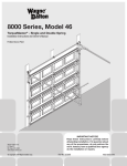
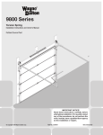
WayneWood Doors
START HERE
8
Models: 40,42,43,45,47
Extension Spring Installation Instructions Layout
IMPORTANT! READ IMPORTANT SAFETY NOTICES AND REFER TO INSERT SHEET INSTRUCTIONS TITLED “REMOVING THE OLD DOOR/PREPARING THE OPENING”. IF THE INSERT SHEET
INSTRUCTIONS ARE NOT INCLUDED, CONTACT WAYNE-DALTON CORP. FOR A FREE COPY. If removing an existing door, carefully follow the directions given on the insert sheet instruction in the portion titled “Removing
the Old Door”.
12A
13A
WARNING!
REMOVAL OF AN EXISTING DOOR CAN BE DANGEROUS. FOLLOW INSERT SHEET INSTRUCTIONS
CAREFULLY, OTHERWISE SERIOUS INJURY OR DEATH COULD OCCUR.
Begin the installation of the door by checking the opening. It must be the same size as the door. Vertical jambs must
be plumb and the header level. Side clearance, from edge of door to wall, must be minimum of 3-1/2” (89 mm) on each
side. For proper opening preparation refer to the portion of the insert sheet instructions titled “Preparing the
Opening”. Follow the steps below. The steps correspond to the illustrations on the garage door layout.
e
11A
r
d
Position flagangle 1-11/16” (43 mm) from the edge of the door. Tighten the first lag screw then secure the flagangle to the
jamb with (2) more 5/16” x 1-5/8” lag screws. Now complete the vertical track installation on both sides by securing the
center jamb brackets and tightening other lag screws.
IMPORTANT! Vertical tracks must be secured so that the rollers are touching the deepest part of the curved side of the
track.
b
3” STEEL SHEAVE WITH
12” RADIUS TRACK
h
1A
Fully adjustable track: Secure the vertical to the lower slot in the flagangle using (1) stud plate and (2) whiz nuts.
NOTE: Some “bolt on track” will have (2) track bolts (k) instead of a stud plate.
10
13B
a
Q.I. Track: Put the lower Twistlock tab on the flagangle into the Twistlock hole in the vertical track. Give the
flagangle 1/4 turn to lock in place. Repeat for other side.
4” STEEL SHEAVE WITH
12” OR 15” RADIUS
TRACK
OPTIONAL SELFDRILLING SCREW
1B-1C
10
Fully adjustable track: To attach the bottom (short) jamb bracket, locate the lower hole/slot pattern in the vertical
track. Align the slot in the jamb bracket with the lower hole of the hole/slot pattern in the vertical track. Secure jamb
bracket with (1) 1/4-20 x 9/16” track bolt and nut. Place the center (long) jamb bracket over the hole/slot pattern
nearest to the center of the track. Loosely fasten the bracket onto the track with (1) 1/4-20 x 9/16” track bolt and nut.
NOTE: Doors over 7’3” high get (3) set of jamb brackets. Install the center and top jamb brackets so that they are
equally spaced in between the flagangle and bottom jamb bracket.
Align the Slidelock™ tabs on the applicable horizontal angle with key slots in the horizontal track. Push the parts
together. Using a hammer, tap the horizontal angle towards the curved end of the track until the hole in track and angle
are aligned. Secure Q.I. horizontal angle and Q.I. track with (1) track bolt and nut in the aligned hole.
b
n
NOTE: For large size doors, a full length horizontal angle is already spot welded to the horizontal track.
3” STEEL SHEAVE WITH
15” RADIUS TRACK
k
11A-11B
To install horizontal track, place the curved end over the top roller. Align the bottom of the horizontal track with the top
of the vertical track. Fully adjustable track: Secure the track to the flagangle with (1) stud plate and nuts. (NOTE: For
“bolt on” track, secure the horizontal track to the flagangle with (2) 1/4-20 track bolts and nuts.) Q.I. Track: Align the
key slot in the track with the quick install tabs on the flagangle. Push the curved portion of the horizontal track
downward to lock into place.
11B
a
9
ALIGN
HOLES
1D
6
Level horizontal track and bolt the horizontal angle to the slot in the flagangle using (1) 3/8-16 x 3/4” truss head bolt and
nut. Repeat for other side. Remove nail which is temporarily holding the top section.
With tracks installed you can adjust the top brackets. Vertically align the top section with the lower sections. Once
aligned, position top roller in adjustable slide against horizontal track, maintain position and tighten nut(s).
Add a 1/4-20 x 11/16” self-drilling screw into the slide to lock the slide in place (see 11B). Repeat for other side.
1-11/16”
(43 mm)
2A
IMPORTANT! Failure to remove nail before attempting to raise door could cause permanent damage to top section.
Bottom brackets are right and left. Before attaching the bottom brackets, secure the counterbalance cables to the
brackets by placing the looped end of the cables over the milford pin. Attach the bottom brackets to the bottom
corners of the sections, aligning the bottom of the bracket with the bottom of the section. Using the bracket as a
template, drill (3) 9/32” (7mm) dia. holes through the section. Secure the bracket to the section with
(3) 1/4-20 x 1-7/8” carriage bolts and hex nuts each. NOTE: Double car doors get (5) carriage bolts and nuts per
bottom bracket (see 2C). Now install a 1/4” x 1” tamper-resistant lag screw into each bottom bracket (Pilot drilling a
1/8” (3mm) dia. hole into the section.
IMPORTANT! When pre-drilling 1/8” hole for tamper-resistant lag be sure NOT to drill through the section).
Insert (1) roller in each bottom bracket.
IMPORTANT! Right and left hand is always determined from inside the building looking out.
Strut Installation (if necessary): Wood doors are provided with short struts and long struts. Center the short strut
onto the bottom rail of the bottom section in between the two bottom brackets. The strut should be at least 3/4”
(19mm) from the bottom of the section. Secure strut using (2) 1” lag screws on each end and center stile locations.
WARNING! DO NOT ATTEMPT TO RAISE DOOR AT THIS TIME.
12B
e
12A-12B
With assistance, raise door until the top section and half of the next section are in a horizontal position. Do NOT raise door
any further since rear of horizontal track is not yet supported.
WARNING!
1A
Hold door in position and clamp locking pliers to vertical track on each side just below bottom rollers. This will prevent
door from lowering. Using perforated angle, fabricate rear support for horizontal tracks as shown.
IMPORTANT! Using 5/16” x 2” lag screws, make sure that support is fastened into ceiling joist, or adequate framing
members to hold the weight of the door. Keeping the horizontal track parallel to the edge of the door sections, raise the
horizontal track to a level position and bolt it to the rear support structure using (1) 5/16” hex bolt and nut on each side.
Track must be secured and braced to prevent movement. The bolt should extend into the track to act as a roller stop.
Repeat for other side.
2B
g
h
j
3A-3B
3-1/4”
a
WARNING! KEEP HORIZONTAL TRACK PARALLEL AND WITHIN 3/4” OF DOOR EDGE,
p
1C
OTHERWISE DOOR COULD FALL FROM TRACKS, RESULTING IN SERIOUS INJURY OR DEATH.
21
8
13A-13B
Using (1) 3/8-16 hex nut, attach the front steel
sheave in the appropriate hole. Repeat for other
side.
k
Strut Installation (if necessary): Place a long strut over the lower hinge leafs of the section and secure the hinges
and strut together to the sections using a (2) strut clips and (2) 1/4-20 x 1-7/8” carriage bolts and hex nuts each.
(See Strutting Schedules on reverse side of this manual.)
Locate the center most stile and mark a vertical line on the section at that point. Measure up 2-1/2” (63mm) from the
bottom of the section (avoiding the strut). Orient the handle vertically and align the lower hole of the lift handle at that
point. Using the lift handle as a template mark the top hole location. Drill (2) 9/32” (7mm) dia. holes through section
at each point. Assemble the outside and inside lift handle back to back with (2) 1/4” x 2-1/2” carriage bolts and nuts.
STRUT
CLIP
5A-5B
1B
1D
k
7A
g
p
a
p
6A-6B
Position the first vertical track over the rollers of the bottom section. Make sure the counterbalance cable is located
between the rollers and the door jamb. Secure jamb brackets and flagangles to the jamb using 5/16” x 1-5/8” lag screws.
Install the other vertical track the same way. Hang counterbalance cables over flagangles.
IMPORTANT! The tops of the vertical tracks must be level from side to side. If the bottom section was shimmed
to level it. The vertical track on the shimmed side, must be raised the height of the shim.
2A
g
Second section lift handle/gripping point Installation
NOTE: Doors with a keyed lock do not require this lift handle.
Locate the inside center stile or the desired lift handle location on the second section of the door. Measure up 4”
(102mm) from the bottom of the second section. Using this measurement as a guide, position lift handle bottom hole
and make a mark at the top hold in lift handle. This should give a min. of 20” (508mm) and a max. of 30” (762mm)
between the lower lift handle and the middle of the upper lift handle. If needed reposition upper lift handle to stay
within min./max. dimension. Drill two 9/32” (7 mm) dia. holes through section. Assemble the outside and inside lift
handles back to back to the section using (2) 1/4-20 x 2-1/2” carriage bolts and nuts.
SPRING LENGTH
E X TE N D E D
(DOOR CLOSED)
6'-0"
25" (635mm)
61" (1549mm)
6'-3"
25" (635mm)
62.5" (1588mm)
6'-6"
25" (635mm)
64" (1626mm)
3” Steel Sheave with 15” radius track Bolt the sheave to the first 13/32” hole in the
horizontal angle.
7'-0"
25" (635mm)
67" (1702mm)
7'-6"
27" (686mm)
72" (1829mm)
7'-9"
27" (686mm)
73.5" (1867mm)
4” Steel Sheave with 12” or 15” radius track Bolt the sheave to the first 13/32” hole in the
horizontal angle.
8'-0"
27" (686mm)
75" (1905mm)
Remove the locking pliers from the vertical tracks
and with assistance raise the door slowly into the
open position making sure the door travels
smoothly through the track. Clamp locking pliers to the back leg of both horizontal tracks, below the bottom rollers to keep the door from falling.
SNUBBER
CABLES
p
i
7B
j
m
p
p
g
OUTSIDE
ANGLED
EXTENSION
2C
p
p
e
2B
j
p
p
3/4”
ROOFING
NAIL
p
i
LEFT HAND BOTTOM
BRACKET
5A
STEEL
SHEAVE
SHEAVE
FORK
HOOK PLATE
NOTE: Adjust snubber cables to be taut.
WARNING
LEVEL
LEFT HAND BOTTOM
BRACKET
DOORS FEATURING 2 PAIRS OF EXTENSION SPRINGS
Position the (1) 5/16-18 x 3-3/4” eyebolt and (1) 5/16”-18 hex nut in the rear support, 6” to 8” (152mm - 203mm) above the
horizontal track. Feed the snubber cable through the rear support and tie the special knot around the “room side” 3 hole clip
as shown. Secure the eyebolt and clip to the rear support with (1) 5/16” - 18 hex nut. Hook one end of the extension spring
onto the eyebolt. Feed the snubber cable through the end spring loop and center of the extension spring then front spring loop,
pull the snubber cable taut and tie the special knot around the “jamb side” 3 hole clip. Attach the “jamb side” 3 hole clip to the
jamb near the flagangle with (1) 5/16” x 1-5/8” lag bolt. If springs are attached to rear support with “S” hooks instead of
eyebolts, then “Room Side” 3 Hole clip is attached to rear support with 1/4”-20 x 5/8” machine bolt and nut.
p
Make sure the top leaves of all hinges on the bottom section are folded down. With assistance lift second section and
place rollers over the tops of the vertical tracks. Install by guiding rollers into the vertical track on both sides and
gently lowering the section onto the bottom section. Keeping the ends of the sections aligned, install remaining
section(s), except top section, in same manner. Fasten all hinges to connect the sections by flipping up the hinge leaf
and securing with (2) 1/4-20 x 1-7/8” carriage bolts and nuts.
7B
SPRING LENGTH
RELAXED
(DOOR OPEN)
14
15
7A
NOTE: To install lock, see lock instructions included in the lock assembly bag.
DOOR HEIGHT
3” Steel Sheave with 12” radius track Bolt the sheave to the 13/32” hole in the top of
the flagangle.
a
4
Before installing the bottom section, measure and cut the vinyl jamb weather-stripping or wood door stops (weatherstripping or wooden stops may or may not be supplied) for entire garage door opening. Vinyl weather seal must be
installed prior to door installation when utilizing fully adjustable track. Attach the weather seal to the jamb 1/8” to
1/4” (3-6mm) past door jamb using the nails supplied with strip. This will help hold the bottom door section in place.
Now, center the bottom section in the door opening. Level it using wooden shims under the bottom seal as needed.
Once the bottom section is level, all the other components will automatically align. Hold the section in the opening
while attaching vertical tracks.
NOTE: In the event that the bottom section was shimmed to level it, then the vertical track on that same side of the
section must be raised the thickness of the shim(s). The tops of the vertical track must be level.
RAISING DOOR FURTHER CAN RESULT IN DOOR FALLING AND CAUSE
SEVERE INJURY OR DEATH.
Align the bottom seal (may not be provided) with the angled extension to the outside of the door (see 2B). Starting at
one end of the door, attach the seal to the bottom of the section with 3/4” long galvanized roofing nails (not supplied).
Stretch the seal slightly and nail the seal to the bottom of the door every 6”.
Locate the lower leaf of the No. 1 end hinges and required No.1 center hinges over the predrilled holes in the end stiles
and center stiles at the top of the bottom section (for strut installation, see below). Secure the hinges to the sections
using (2) 1/4-20 x 1-7/8” carriage bolts and hex nuts each. Insert (1) roller in each end hinge. Repeat using No. 2 end
hinges for second (lock) section and No. 3/No.4 hinges for the third/forth (intermediate) section(s).
IMPORTANT! Do NOT over tighten hex nuts.
IMPORTANT! When placing rollers into end hinges No. 2 and higher, the roller must be inserted into the tube
furthest away from section. See 3B.
Place the top section in the door opening. Keeping the ends of the sections aligned, secure it temporarily by driving a nail
into the header near the center of the door and bending it over the section. Once section is secure, fold the upper leaves
of the hinges from the section below to the top section and secure with (2) 1/4-20 x 1-7/8” carriage bolts and nuts.
9
b
NOTE: It is recommended that 5/16” x 1-5/8” and 2” lag screws be pilot drilled using a 3/16” (5mm) drill bit, and
1/4” x 1” lag screws be pilot drilled using 1/8” (3mm) drill bit, prior to fastening.
Q.I. Track: Using the Quick Install Jamb Bracket Schedule (located on the reverse side), determine the placement of
the jamb brackets for your door height. Align the Twistlock™ wings on each jamb bracket with the correct butterfly
hole in the track and turn the jamb bracket perpendicular to the track so the mounting flange is toward the back leg of
the track.
14
r
Identify the supplied top brackets. Measure down from the top of the section 3-1/4” (83mm) and mark location. Align
the top holes on the top bracket with the mark and align the edge of the bracket with the edge of the section. Using the
top bracket as a template, drill (4) 9/32” (7mm) holes through the section. Secure the brackets using (4) 1/4-20 x 1-7/8”
carriage bolts and hex nuts each. Insert a roller into each top bracket and loosen the bolt in the adjustable slides. Proper
adjustment will be required once the track is installed.
Strut Installation (if necessary): Center the short strut onto the top of the top section in between the two top
brackets. The strut should be at least 3/4” (19mm) from the top of the section. Secure strut using (2) 1” lag screws on
each end and center stile (aligned with hinges) locations.
m
g
WEATHER
SEAL
4
3B
3A
FAILURE TO INSTALL SNUBBER CABLES CAN RESULT IN SEVERE INJURY OR DEATH IN CASE OF SPRING
BREAKAGE.
p
m
p
Hook the sheave fork through the front loop of the extension spring and attach the sheave fork to the rear 3” steel sheave
using (1) 3/8” -16 x 1-1/2” bolt and nut. Thread the counterbalance cable over the front sheave, around the rear sheave and
tie the special knot around the “horizontal angle” 3 hole clip. Insert one end of the large “S” hook in the “horizontal angle”
3 hole clip and the other end in the second slot of the horizontal angle. Close “S” hook and eye bolt to prevent spring(s) from
coming loose. Repeat for the other side.
IMPORTANT! Close “S” hooks and eye bolts to prevent springs from coming loose.
JAMB
DOOR
1/8”-1/4”
e
5B
p
m
2-1/2”
p
WARNING
FAILURE TO CLOSE “S” HOOKS AND EYE BOLTS CAN RESULT IN SEVERE INJURY OR DEATH IN CASE
SPRINGS COME LOOSE.
CONTINUE INSTALLATION INSTRUCTIONS ON REVERSE SIDE.
5/16”-18 Hex Nut
#100256
Stud Plate
#266102
11. Check all bolted connections monthly during the lifetime of the door to prevent damage or personal
injury caused by loose connections.
12. Definition of key words used in this manual:
1/4”-20 x 5/8”
Carriage Bolt
#262617
k
Track Bolt
#200527
f
5/16” x 1-5/8” Tamper-Resistant Lag Screw
#107801
q
5/16” x 2” Tamper-Resistant Lag Screw
#141888
WARNING! -- Indicates a potentially hazardous situation which, if not avoided, could result
in serious injury or death.
IMPORTANT! -- Required step for safe and proper door operation.
NOTE: -- Information assuring proper installation of the door.
© Copyright 2003 Wayne-Dalton Corp.
INSTALLATION INSTRUCTIONS CONTINUED.
NOTE: Some larger doors feature 2 pairs of extension springs. A snubber cable must be installed through each spring
Adjust counterbalance cables to create about 1” to 2” (25 mm to 50 mm) of spring stretch. Measure relaxed spring length for
your door height and verify with chart. Spring length must be the same for both springs to allow even door balance. Carefully
remove the locking pliers from the horizontal track and lower the door into the closed position. Once the door is closed,
measure the spring length in tension for both sides. Using the chart, verify the spring length in tension is correct with your door
height.
WARNING!
Strutting Schedule: Doors 8 ft. high and below
DO NOT INSTALL OPERATOR OFF CENTER WITH EXTENSION SPRING DOORS.
IMPORTANT! ANGLE MUST BE
ATTACHED TO FRAMING
MEMBERS
NOTE: It may be necessary to adjust spring length for proper door balance.
Permanently attach the vinyl weather stripping to both door jambs and the header. Now lift the door and check it’s balance.
If the door is hard to pull down or lifts by itself, adjust spring length by moving the “S” hook backward (towards the rear support)
to a different hole in the reinforcing angle. If the door is difficult to lift or too easy to pull down, adjust spring length by moving
the “S” hook forward (towards the header) to a different hole in the reinforcing angle.
IMPORTANT! Whenever adjusting spring length for door balance, always open the door to the fully open position and return
the locking pliers to the horizontal tracks below the bottom rollers.
Product
Door Width
8'-0" to 12'-2"
Door Width
12'-3" to 16'-0"
Door Width
16'-1" to 18'-0"
Model
40,42,43,45,47
**(3) 2" U-Bars
**(3) 2" U-Bars
**(3) 3" U-Bars
* (2) SHORT (SECTION WIDTH MINUS 13”) U-BARS AND (2) LONG (SECTION WIDTH MINUS 1”) U-BARS
WITH HOLES
** (2) SHORT U-BARS AND THE REST LONG U-BARS WITH HOLES
Strutting Schedule: Doors greater than 8 ft. high
ATTACH OPERATOR RAIL
SECURELY TO SPRING PAD
If the door still does not operate easily, lower the door into the closed position and recheck the following items:
1.) Check the door for level.
2.) Check the distance between flagangles - must be door width plus 3-3/8” +1/4” -0”.
3.) Check the counterbalance cables for equal tension when the door is in the open position - adjust by re-tieing the special knot,
if necessary.
15
Product
Door Width
8'-0" to 10'-2"
Door Width
10'-3" to 16'-0"
Door Width
16'-1" to 18'-0"
Model
40,42,43,45,47
** (1) 2" U-Bar
per section
** (1) 2" U-Bar
per section
** (1) 3" U-Bar per
section
Twist the No. 6 screw eye into the wood jamb approximately 48” to 50” (1220 to 1270 mm) from the floor. Tie the pull
rope to the screw eye and to the bottom bracket as shown.
* (2) SHORT (SECTION WIDTH MINUS 13”) U-BARS AND (2) LONG (SECTION WIDTH MINUS 1”) U-BARS
WITH HOLES
CHILDREN MAY BECOME ENTANGLED IN THE ROPE CAUSING INJURY OR DEATH.
TYPICAL OPERATOR INSTALLATION
If you are installing an electric operator on your door, the following information is provided to ensure proper function of
your door/operator installation. See fig. 21 (on reverse side) for a typical operator arm installation.
1. Follow the installation instructions supplied with your operator.
2. Reinforce top section per manufacturer’s recommendation prior to attaching operator.
3. Install trolley rail 1/2” to 1-1/2” (13 - 38 mm) above high arc of top section of the door.
4. Mount operator to ceiling so that 1” to 1-1/2” (25 - 38 mm) clearance is maintained between trolley rail and top section
when door is fully open (trolley rail will slope down towards rear).
5. The operator bracket must be mounted to the operator stile on the top section so it bridges the transition point in section
thickness.
6. Attach operator rail to spring pad (vertical wood support above center of header).
7. Attach operator to ceiling using perforated angle.
8. IMPORTANT! Angle(s) must be attached to framing member(s).
WARNING! OPERATOR MUST BE
TESTED AT TIME OF INSTALLATION AND MONTHLY
THEREAFTER TO ENSURE THAT DOOR REVERSES ON
CONTACT WITH 2 X 4 BOARD LAID FLAT UNDER THE
DOOR. FAILURE TO ADJUST OPERATOR, IF NECESSARY, CAN RESULT IN SEVERE INJURY OR DEATH. IF
YOUR OPERATOR IS EQUIPPED WITH PHOTOELECTRIC SYSTEM, THEN THIS MUST BE TESTED AT THE
SAME TIME TO ENSURE THAT DOOR DOES NOT
CLOSE AND A CLOSING DOOR OPENS IF SYSTEMS
IS OBSTRUCTED. FAILURE TO MAKE ADJUSTMENTS,
IF NECESSARY, CAN RESULT IN SEVERE INJURY OR
DEATH.
Yearly inspection of all the surfaces of the garage door(s) will reveal the extent of weathering and the
need for refinishing. When the finish becomes eroded or thin, clean and prime the areas of
deterioration. Follow up with a complete refinishing of the door(s), according to the above directions,
as well as the manufacturer’s label directions. Protecting the door(s) from prolonged exposure to
moisture and sunlight is vital in extending the service life of your garage door(s).
© Copyright 2003 Wayne-Dalton Corp.
Residential Wood Panel
** (2) SHORT U-BARS AND THE REST LONG U-BARS WITH HOLES
INSTALL FRONT OF TROLLEY RAIL 1” TO 1-1/2”
(25 - 38 MM) ABOVE HIGH-ARC OF SECTIONS
The Manufacturer warrants Wood Doors will be free from defects in material and workmanship for a
period of ONE YEAR from the time of delivery, provided the interior and exterior surfaces, as well as all
edges of the wood doors are properly finished according to Wayne-Dalton Corp.’s Maintenance and
Painting Instructions and the finish manufacturer’s instructions. All surfaces of wood doors must be
protected with three(3) coats of paint, including primer, or three(3) coats of urethane finish, whether
wood is stained or left natural, prior to any exposure of the doors to moisture. Non-finished doors
must be protected from exposure to moisture during transportation and storage. Sections should not be
installed until they have been finish painted or stained and sealed with urethane finish. IMPROPER
STORAGE, TRANSPORTATION OR DELAYS IN FINISHING THAT EXPOSE WOOD SURFACES TO
MOISTURE OR OTHER CONTAMINANTS, WILL RESULT IN THIS WARRANTY BEING VOIDED.
The Manufacturer warrants the garage door hardware, track, and springs against defects in workmanship
or material for a period of ONE YEAR from time of installation.
Manufacturer shall, upon notification, correct such nonconformity at its option, by repairing or replacing
any defective part(s). This warranty covers material only and excludes all other charges incurred.
The Manufacturer shall not be responsible for any damage resulting to or caused by its products by
reason of installation, improper storage, unauthorized service, alteration of products, neglect or abuse, or
attempt to use the products for other than the customary usage or for their intended purposes. The above
warranty becomes null and void if holes are drilled other than those specified by the Manufacturer. This
warranty does not cover the product due to circumstances such as normal wear, damage from corrosive
fumes or substances, fire, condensation, vandalism, acts of God, or other causes beyond Manufacturer’s
control, nor replacement or repair labor.
IF THIS WARRANTY COVERS A CONSUMER PRODUCT AS DEFINED BY THE MAGNUSON-MOSS
WARRANTY ACT, NO WARRANTIES, EXPRESSED OR IMPLIED, (INCLUDING, BUT NOT LIMITED
TO, THE WARRANTY OF MERCHANTABILITY OR FITNESS FOR A PARTICULAR PURPOSE), SHALL
EXTEND BEYOND THE APPLICABLE TIME PERIOD STATED IN BOLD FACE TYPE ABOVE.
Claims for defects in material and workmanship covered by this warranty shall be made in writing to the
dealer from whom the product was purchased within the warranty period. Manufacturer may either send
a service representative or have the product returned to the Manufacturer at Buyer’s expense for inspection.
If judged by Manufacturer to be defective in material or workmanship, the product will be replaced or
repaired at the option of Manufacturer, free from all charges except authorized transportation and
replacement labor.
THE REMEDIES OF BUYER SET FORTH HEREIN ARE EXCLUSIVE AND ARE IN LIEU OF ALL OTHER
REMEDIES. THE LIABILITY OF MANUFACTURER, WHETHER IN CONTRACT, TORT, UNDER ANY
WARRANTY, OR OTHERWISE, SHALL NOT EXTEND BEYOND ITS OBLIGATION TO REPAIR OR
REPLACE, AT ITS OPTION, ANY PRODUCT OR PART FOUND BY MANUFACTURER TO BE DEFECTIVE
IN MATERIAL OR WORKMANSHIP. MANUFACTURER SHALL NOT BE LIABLE FOR COST OF
REMOVAL OR INSTALLATION OR SHALL NOT BE RESPONSIBLE FOR ANY DIRECT, INDIRECT,
SPECIAL OR CONSEQUENTIAL DAMAGES OF ANY NATURE.
CENTER
STILE
Quick Install Jamb Bracket Schedule
This warranty gives you specific legal rights, and you may also have other rights, which may vary from
state to state. However, some states do not allow limitations on how long an implied warranty lasts or the
exclusion or limitation of incidental or consequential damages, so the above limitations or exclusions may
not apply to you.
© Copyright 2003 Wayne-Dalton Corp.
Fully Adjustable Track Jamb Bracket Schedule
INSTALL THE SHORTEST JAMB BRACKET ON THE
BOTTOM HOLE/SLOT PATTERN. THE CENTER JAMB
BRACKET(S) IS/ARE CENTERED BETWEEN THE BOTTOM
JAMB BRACKET AND FLAGANGLE.
LIMITED WARRANTY
NO EMPLOYEE, DISTRIBUTOR, OR REPRESENTATIVE ISAUTHORIZED TO CHANGE THE FOREGOING
WARRANTIES IN ANY WAY OR GRANT ANY OTHER WARRANTY ON BEHALF OF MANUFACTURER.
WARNING! DO NOT INSTALL PULL ROPES ON DOORS WITH ELECTRIC OPERATORS.
16
Maintenance and Refinishing
WayneWood - Extension Spring
Models: 40,42,43,45,47
Installation Instructions and Owners Manual
r
www.wayne-dalton.com
1/4” x 1” Lag screw
#296575
10. If your existing garage door opener does not have a reversing mechanism, you should consider
purchasing one that has up to date safety features. These features can prevent opener related property
damage or personal injury.
If staining, apply an exterior grade stain, approved for use on each species of wood substrate being
finished, to the interior and exterior surfaces, as well as all edges, following stain manufacturer’s label
directions. The stain selected must be compatible with the urethane finish that will be used to finish the
door. After proper drying time for the stain (or if stain in not being applied), apply 1 coat of urethane
finish to the interior and exterior surfaces, as well as all edges. After recommended drying time of 1st
coating, sand with a fine grit (320) sandpaper. Clean all surfaces of sanding dust and apply a 2nd coat of
the urethane coating to the interior and exterior surfaces, as well as all edges,. After 2nd coat is dry,
sand with a fine grit (320) sandpaper again. Clean all surfaces of sanding dust and apply a final 3rd
coat. Three urethane finish coats are required for proper finish. Follow the finish manufacturer’s label
directions completely for each coating applied. (NOTE: Do not stain MDO plywood, apply paint only.
Only a urethane finish is an approved top coat for stained or natural doors. Other types of top coat
finishes, including deck sealers, are not acceptable and if used, will void the warranty.
U
j
9. Door is constantly under EXTREME SPRING TENSION. To prevent possible serious injury or death,
adjustments, repairs, removal or installation, ESPECIALLY of SPRING ASSEMBLIES, CABLES or
BOTTOM CORNER BRACKETS, should be performed ONLY by qualified door service people.
X
5/16” x 1-5/8” Hex Head Lag Screw
#100292
3/8” x 1-1/2” Hex Head Bolt
#107645
1/4”-20 Hex Nut
#107703
L1
n
p
A2
1/4”-20 x 2-1/2” Carriage Bolt
#107687
R
m
O
1/4” x 1” Tamper-Resistant Lag
Screw
#141887
Parts List
i
Z
1/4”-20 x 1-7/8” Carriage Bolt
#102843
T
e
g
P
3/8”-16 x 3/4” Truss Head Bolt
#154531
3/8”-16 Hex Nut
#100313
h
c
d
A1
b
1/4”-20 Flanged Hex Nut
#100279
G
a
Clear or Stained Finishes
M
8. To prevent serious injury or death, avoid standing in the open doorway or walking through the doorway
while the door is moving.
Y
(2) Locking Pliers
7. DO NOT PERMIT children to play with the garage door or the electrical controls. Fatal injury could
result, should the child become entrapped between the door and the floor.
S
7/16” Drill Bit (Step Plate)
9/32” Drill Bit
(2 or 3) Saw Horses or other supports for
1/8” Drill Bit
placing sections on while assembling
J2
6. Should the door become hard to operate or completely inoperative, a qualified door agency should
correct the problem to prevent damage to the door or serious personal injury.
C
5. Operate door ONLY when properly adjusted and free of obstructions.
(1) 7/16” Hex
Head Driver
J1
(1) Electric Drill
with Clutch
When painting a door, the finish coat base must be the same as the primer coat base. A latex based
finish paint is recommended for use over a latex based primer, and an oil based finish paint is
recommended for use over an oil based primer. Prime the interior and exterior surfaces, as well as all
edges, using paint approved for use on the specific species of wood substrate being finished. (Note:
Some species of wood, such as cedar, require special primers and finishes to prevent tannin stains from
appearing. Consult with your paint supplier.) If the door is factory primed by Wayne-Dalton Corp., the
priming step is not required, unless touch-up is needed due to surface preparation and re-sanding.
(Note: Wayne-Dalton Corp. uses a latex primer, so latex finish paint is required.) Finish paint the interior
and exterior surfaces, as well as all edges with at least 2 coats of finish paint over the primer. Follow
paint manufacture’s label directions completely for all coatings.
N
4. If the door is to be electrically operated at any time, all pull ropes MUST be removed to prevent injury or
death to children who may become entangled in the rope. The locking mechanism MUST also be disengaged.
(50) 1-1/2”
Common Nail
Painted Finishes
D
3. Avoid installing your new door on windy days. Door could fall during the installation and cause damage
and personal injury.
(1) Ratchet with 7/16”,
1/2”, 9/16” sockets
(1) Level (2’ Minimum Length)
All surfaces must be clean, free of dust and dirt and any other contamination. Any scarring or stains
that occur during transportation, handling and storage must be re-sanded to the original condition.
V
(1) Hammer
Surface Preparation
F2
2. It is always recommended to wear eye protection when using tools, otherwise serious eye injury could
result.
W
1. Wear protective gloves during installation to avoid possible cuts from sharp metal edges.
F1
(1) Tape Measure
(1) Screw Driver
(Standard Blade)
B1
Read these instructions carefully before attempting installation. If in question about any of the procedures, do not perform the work. Instead, have a qualified door agency do the installation or repairs.
B2
Safety Glasses
(A1) TOP BRACKET (BASE)
# 270343
(A2) TOP BRACKET (SLIDE)
# 270344
(B1) BOTTOM BRACKET (RIGHT)
# 295763
(B2) BOTTOM BRACKET (LEFT)
# 295762
(C) ROLLER
# 100269
(D) VERTICAL TRACK
1 PAIR
(E1) QIJB-6 JAMB BRACKET
# 297925
(E2) QIJB-7 JAMB BRACKET
# 297926
(E3) QIJB-8 JAMB BRACKET
# 297927
(F1) ST-0 JAMB BRACKET (SHORT)
# 287665
(F2) ST-1 JAMB BRACKET (LONG)
# 270345
(G) HORIZONTAL TRACK
1 PAIR
(H1) R 12” Q.I. FLAGANGLE (LEFT, 18-1/2”)
# 292532
(H2) R 12” Q.I. FLAGANGLE (RIGHT, 18-1/2”)
# 292533
(J1) R 12” UNIV. FLAGANGLE (LEFT, 18-1/16”)
# 285206
(J2) R 12” UNIV. FLAGANGLE (RIGHT, 18-1/16”)
# 285207
(K1) R 15” UNIV. FLAGANGLE (LEFT, 19-7/16”)
# 285214
(K2) R 15” UNIV. FLAGANGLE (RIGHT, 19-7/16”)
# 285215
(L1) 23-3/32” HORIZ. ANGLE
# 292537
(L2) 80-5/8” HORIZ. ANGLE QI (RIGHT)
# 292541
(L3) 80-5/8” HORIZ. ANGLE QI (LEFT)
# 292540
(M) EXTENSION SPRING
1 PAIR
(N) COUNTERBALANCE CABLES
1 PAIR
(O) 3” STEEL SHEAVE
# 100377
(O) 4” STEEL SHEAVE
# 102842
(P) 3” STEEL SHEAVE W/STUD MOUNT
# 290966
(P) 4” STEEL SHEAVE W/STUD MOUNT
# 290967
(R) 5/15-18 X 3-3/4” EYE BOLT
# 100004
(S) S-HOOK
# 100593
(T) 1/8” DIA. SNUBBER CABLE
# 101825
(U) REAR SUPPORT
SOLD SEPARATELY
(V) # 6 SCREW EYE
# 100362
(W) 60” PULL ROPE
# 274884
(X) STRUTS
AS REQUIRED
(Y) 3-HOLE CLIP
# 100259
(Z) 3” SHEAVE FORK
# 100262
(1) 7/16” Wrench
(1) 1/2” Wrench
(1) Step Ladder
Wood doors must be completely finished (3 top coats) prior to installation, to ensure that the interior
and exterior surfaces, as well as all edges of the doors are properly protected against moisture or other
contaminants. Wood doors, in a non-finished condition, must not be transported or stored where the
wood surfaces can be exposed to moisture or other contaminants. IMPROPER STORAGE,
TRANSPORTATION OR DELAY IN FINISHING, THAT EXPOSE WOOD DOOR SURFACES TO
MOISTURE OR OTHER CONTAMINANTS, WILL RESULT IN THE WARRANTY BEING VOIDED.
04/15/2003
Gloves
Wayne-Dalton Corp.
P.O. Box 67
Mt. Hope, Ohio 44660
Rev
(1) Screw Driver
(Phillips Blade)
The purpose for painting is to both protect and beautify the substrates. These requirements for
finishing are intended to achieve both functions for reasonable service life of wood doors.
NOTE: Depending on the door model, some parts listed will not be supplied if not necessary.
(1) Pliers
These instructions apply to all Wood Doors produced and sold by Wayne-Dalton Corp. The interior
and exterior surfaces, as well as all edges must be properly primed, painted and maintained if
satisfactory performance is to be achieved.
PART NO. 307326
IMPORT
ANT
IMPORTANT
SAFETY NOTICES
Maintenance and Painting Instructions for All Wood Doors
© Copyright 2003 Wayne-Dalton Corp.
Required Tools
CENTER JAMB
BRACKET
(LONGEST)
D oor
Height
1st S et
2n d S et
3rd Set
6'-6"
QIJB-7
TOP
QIJB- 8
MID
N/A
7'-0"
QIJB-7
TOP
QIJB- 8
MID
N/A
7'-6"
QIJB-6
TOP
QIJB- 7
BOT
QIJB- 8
BOT
8'-0"
QIJB-6
TOP
QIJB- 7
BOT
QIJB- 8
BOT
3RD
SET
2ND
SET
1ST
SET
NOTE: Jamb brackets are stamped for identification.
NOTE: DOORS OVER 7’3” HIGH GET
(3) SETS OF JAMB BRACKETS.
INSTALL THE CENTER AND TOP
JAMB BRACKETS SO THAT THEY
ARE EQUALLY SPACED IN BETWEEN
THE FLAGANGLE AND BOTTOM
JAMB BRACKET.
NOTE: THE BOTTOM JAMB
BRACKET IS THE SHORTEST
IS LENGTH. IT DOES NOT
NECESSARILY MEAN THE
“SHORT” (ST-0) JAMB
BRACKET.
CENTER JAMB
BRACKET
BOTTOM JAMB
BRACKET
(SHORTEST)
NOTE: Jamb brackets are stamped for identification.