1
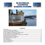
EZ HANDRAIL® ROUND ALUMINUM RAILING SYSTEMS ADA CODE COMPLIANT HANDRAILS FOR YOUR LIFESTYLE CONTENTS Introduction .................................................................................................................................... 2 Tools You Will Need (not included) for Single EZ Handrail Installation............................................ 3 EZ Round Handrail Components (sold separately) ........................................................................... 4 Fasteners Included with EZ Wall Brackets (EZA200) ....................................................................... 5 Components Assembly Exploded Diagram ....................................................................................... 6 Single EZ Round Handrail Assembly and Wall Installation ............................................................... 7 Installing Multiple EZ Round Handrails with existing posts or EZ Posts ........................................... 9 EZ Post Installation with Separate Mounting Flange ..................................................................... 11 EZ Post Installation with Welded Base Plate ................................................................................. 12 Stair Handrail Helpful Hints & Apps ............................................................................................... 15 Care and Maintenance ................................................................................................................... 16 10-year Limited Warranty ............................................................................................................. 16 Engineered Drawings..................................................................................................................... 17 Congratulations! Congratulations! You are on your way to a maintenance free handrail system that is easily assembled and installed. With your EZ Handrail system, you’ll feel safe being protected by the tremendous strength of its aluminum alloy components, plus be comforted knowing the hardened powder coated finish will last year after year. Please take a moment to read the instructions before you begin assembling your EZ Handrail. Introduction Check the contents of EZ Handrail box with these instructions to verify all parts are present. This will allow you to become familiar with the components of your new EZ Handrail system. Inspect all component parts for familiarity Layout recommended tools Before cutting any component, know its use – “measure twice and cut once.” The included concrete fasteners are for brick and concrete. EZ Round Handrail shown with EZ Square Baluster Railing and EZ Posts sold separately www.ezhandrail.com for videos 2 Tools You Will Need (not included) EZ Handrail Installation Level Tape Measure Chop Saw (60 tooth wood blade) 60-80 tooth standard wood saw blade (non ferrous, carbide is OK) Screw or Impact Gun w/ Phillips head ¼” & 5/16” Hex Bit Drivers Vise Grips Rubber Mallet Safety Glasses Drill Bits: ¼” x 4” wood ¼” x 3 ½” concrete 1/8” metal/wood For saltwater environments we recommend grade 18-8 stainless steel fasteners or equivalent. Stainless steel fasteners not included. www.ezhandrail.com for videos 3 EZ Round Handrail Components (sold separately) 1.9” outside diameter, Schedule 40 Pipe (EZA100) Wall Bracket (EZA200) End Loop (EZA300) End Bracket (EZA400) End Cap (EZA410) Miter Elbow 90˚ (EZA500) Adjustable Angle (EZA555) www.ezhandrail.com for videos Wall Return (EZA575) 4 EZ Round Handrail Components (sold separately) Radius Elbow 90˚ (EZA585) 5” Internal Splice (EZA650) 3” Internal Splice (EZA600) Included w/ components Fasteners Included with EZ Wall Brackets (EZA200) 2 ¼” tapcon used for wood & concrete www.ezhandrail.com for videos 1” Phillips Pan Head Fastener (stainless steel) 5 Components Assembly Exploded Diagram Components: A. 1.9 Round Handrail B. Wall Bracket C. End Loop D. Miter Elbow E. Adjustable Angle F. Wall Return G. Radius Elbow www.ezhandrail.com for videos 6 EZ Round Handrail Step-by-Step Installation EZ Handrail’s versatility allows for many different types of installations. Therefore, the following step-by-step instructions are separated into two sections: 1. Single EZ Handrail attached to a stairwell wall. 2. Mutiple EZ Handrails attached to existing or EZ Posts incorporating multiple handrail components and connections. This is a more complex handrail system. Please refer to the instruction set below that best matches your installation: Single EZ Round Handrail Assembly and Wall Installation 1. 2. 3. Determine handrail installation location. Determine stud or secure mounting location for wall brackets. On the ground, layout handrail and wall brackets to ensure you will achieve your desired look and symmetry once the handrail is installed. 4. Starting with the upper most wall bracket (high end of handrail), measure from the nose of your stair tread up the wall 34” – 38” and using the wall bracket as a guide, make a pencil mark where the wall bracket fastener is to be installed. 5. Drill a 1/8” pilot hole into the wall for the wall bracket fastener. Important: Ensure your pilot hole is hitting a solid mounting surface (e.g. a stud behind the drywall)!!! Hint: If you are searching for a stud, using a smaller drill bit as it leaves less repairs for later. 6. Loosely attach wall bracket to your mounting surface (wall) with the appropriate included fastener. 7. Set the handrail on the upper wall bracket (while supporting the other end) and again check for desired look and symmetry. 8. Cut (size) the handrail if necessary. REMEMBER, BEFORE MAKING YOUR CUT THAT ALL WALL BRACKETS MUST ATTACH TO A SOLID MOUNTING SURFACE (STUD). 9. With the handrail in place on the upper wall bracket (and supporting the other end) drill 1/8” pilot holes through the bracket and into the handrail. Important: Make sure the handrail is seated properly when drilling the holes! 10. Loosely fasten handrail to the wall bracket using the 1” Phillips head fasteners provided. 11. Next, move to the lowest wall bracket (low end of handrail), measure www.ezhandrail.com for videos 7 12. 13. 14. 15. 16. from the nose of your stair tread up the wall 34” – 38” and using the wall bracket as a guide, make a pencil mark where the wall bracket fastener is to be fastened into the wall. Hint: You can use an angle finder app on your Smartphone or the rise/run chart at the end of these instructions to double check that your handrail is angled parallel to your stairs. Drill a 1/8” pilot hole for the wall bracket fastener. Important: Ensure your pilot hole is hitting a solid mounting surface (stud). Loosely attach wall bracket to your mounting surface (wall). Loosely fasten handrail to the wall bracket using the 1” Phillips head fasteners provided. Uniformly position and install all intermediate wall brackets (incrementally every 4’ to 6’ and loosely attach to handrail. Once all the wall brackets, handrail, and handrail components are loosely fastened in place, firmly secure (tighten down) the handrail system – starting with tightening the wall brackets into the wall. Note: Additional fasteners may be piloted and fastened into the wall brackets for additional support. www.ezhandrail.com for videos 8 Installing Multiple EZ Round Handrails with existing posts or EZ Posts STEP 1: Planning 1. 2. 3. 4. 5. STEP2: Install 6. 7. 8. 9. 10. 11. 12. 13. 14. 15. 16. www.ezhandrail.com for videos Layout handrail installation locations. Layout posts spaced 6’ or less apart (4’ for commercial ADA codes). Layout handrail connection components (e.g. radius corners, adjustable angles). Ensure post configuration will support proposed handrail configuration. Important: Adjustable angles require post support on both sides. End loops require two wall mounts and end cap. Verify secure mounting locations for all wall brackets and appropriate fasteners. Set EZ Posts every 4’ to 6’ following the EZ Post instructions found on subsequent pages. On the ground, layout handrail and wall brackets to ensure you will achieve your desired look and symmetry once the handrail is installed. Starting with the upper most wall bracket (high end of handrail), measure from the nose of your stair tread or ramp up the post 34” – 38.” Determine your desired installed handrail height, 34”-38” meets all building codes. Using the wall bracket as a guide, make a pencil mark where the wall bracket fastener is to be installed. Drill a 1/8” pilot hole into the post for the wall bracket fastener. Important: Ensure your pilot hole is hitting a solid mounting surface. Loosely attach wall bracket to the EZ post using 3 3/4” bolts, washers and lock nuts (sold separately at Home Depot Fastener Dept.). If installing to existing posts use appropriate fasteners. Set the handrail on the upper wall bracket (while supporting the other end) and again check for desired look and symmetry. Cut (size) the handrail if necessary. REMEMBER, BEFORE MAKING YOUR CUT THAT ALL WALL BRACKETS MUST ATTACH TO A SOLID MOUNTING SURFACE (STUD). Splice together handrails as necessary using vise grips on the 5” splice. Add epoxy to all connections. NOTE: At this point it is sometimes easier to complete Step 12 prior (attaching handrail components) to Step 10. Distribute the splice evenly between both handrails. Install wall returns, elbows and other components using the provided 3” splices. Note: splices require epoxy. Use vise grips to compress splice and slide components together. Next, move to the lowest wall bracket (low end of handrail), measure from the nose of your stair tread up the post 34” – 38” and using the wall bracket as a guide, make a pencil mark where the wall bracket fastener is to be fastened into the wall. Hint: You can use an angle finder app on 9 17. 18. 19. 20. 21. 22. your Smartphone or the rise/run chart at the end of these instructions to double check that your handrail is angled parallel to your stairs or ramp. Drill a 1/8” pilot hole for the wall bracket fastener. Important: Ensure your pilot hole is hitting a solid mounting surface if not installing onto EZ Posts. Drill ¼” hole and loosely bolt wall bracket to the EZ Post. Loosely fasten handrail to the wall bracket using the 1” Phillips head fasteners provided. See step# 10. Uniformly position and install all intermediate wall brackets and loosely attach to handrail. Once all the wall brackets, handrail, and handrail components are loosely fastened in place, firmly secure (tighten down) the handrail system – starting with tightening the wall brackets into the posts. Please refer to Permatex Multi-Metal cure times before allowing access to the newly installed handrails. Note: Additional fasteners may be piloted and fastened into the wall brackets for additional support. www.ezhandrail.com for videos 10 EZ Post Installation with Separate Mounting Flange Ensure that you have a solid mounting surface for your EZ Post base fasteners. Existing posts or the EZ Posts (sold separately), may be used with this system. If you are installing EZ Posts, refer to the steps and illustration below. 1. Layout posts uniformly or as desired across entire project. 2. Ensure spacing between posts does not exceed 6 ft. for installs above 24” above the ground (or greater than local codes specify). Commercial ADA codes require 4’ spacing. 3. Attach post flange to concrete/wood using appropriate fasteners provided with the EZ Post Kit. MAKE SURE TO USE ADDITIONAL LUMBER BLOCKING UNDER THE DECK TO SECURELY FASTEN THE FLANGE!!! In some instances, fully threaded lag screws may be necessary – but are not included. LAG SCREWS LOOSEN OVER TIME AND REQUIRE QUARTERLY SAFETY CHECKS. 4. Slide 3”x3” post over post flange and plum using level. 5. Drill ¼” hole front-to-back through the entire post and post flange coming out on the back side. IT IS IMPORT TO DRILL HOLES WITH POST LEVEL. 6. Drill 2nd ¼” hole front-to-back. Start hole 1” above the first hole. The vertical hole pattern creates the best deflection strength. Note that hole patterns can be modified if necessary. 7. Fasten post to post flange with 3 ½” bolt, washers, and standard nut provided. Washers must be placed on both sides of the post. 8. After post is level and securely fastened, slide decorative base cover (optional and sold separately) over post covering the post flange. 9. Secure next post using same procedure. 3” x 3” Aluminum EZ Post IMPORTANT: The distance between posts should not exceed 6 ft. when installed above ground level. Always refer to your local building department for building code clarification. Note: When installing the post base into ACQ lumber, use stainless steel bolts (not included) www.ezhandrail.com for videos 11 EZ Post Installation with Welded Base Plate Start by ensuring that you have a solid and level mounting surface for your Post(s). Washers or galvanized/stainless metal shims (not included) may be used to plum posts. Installation into wood/composite decking/Non ACQ lumber: STEP 1: 1. Determine the 3”x3” post location(s). Spacing between posts should be 6’ or less to meet IBC codes when installed 24” or higher above the ground. 2. We recommend the edge of the 5”x5” base plate is fastened at least 3” in from the edge of the deck (do not lag screw into the rim joist unless absolutely necessary). 3. Reinforce the decking with support lumber “backer board”. A piece of 2”x10” lumber cut to fit tightly between the joists and installed flat under the decking works great. 4. Square up the post with the deck and mark all (4) holes with a pencil. 5. At your (4) pencil marks, drill a ¼” hole through the decking and backer board. 6. Using a 7/16” socket bit in your drill, thread the ¼”x4” Thru Bolt into the post plate, through the deck, and through the backer board. ** 7. Thread the Tee Nut onto the 4” Thru Bolt underneath the decking and support lumber. 8. Tighten post firmly to deck. Do not overtighten. 9. Slide on optional post base cover to hide fasteners. 10. Attach post cap after railing has been installed using 1” fasteners provided. ** Note: The 4” Thru Bolt fits very tightly into the post base plate (especially Textured Black Posts due to thicker powder coat finish) and in some cases must be predrilled using a ¼” drill bit. www.ezhandrail.com for videos 12 Installation into concrete STEP 1: www.ezhandrail.com for videos 1. Turn the post upside down on a hard surface and prepare to drill larger holes in base plate. Enlarge the (4) existing post base plate holes to 5/16” (using a 5/16” drill bit). 2. Determine the 3”x3” post location(s). Spacing between posts should be 6’ or less to meet IBC codes when installed 24” or higher above the ground. 3. We recommend the edge of the 5”x5” base plate is fastened at least 3” in from the edge of any concrete face (assuming normal weight concrete). 4. Square up the post with the concrete surface and mark all (4) holes with a marker. 5. At your (4) marks, drill a 1/4” x 3 ½” or deeper hole into the concrete using a masonry bit. 6. Fasten post in place with provided ¼” x 3” Powers Wedge Bolts. 7. Begin tightening the anchor with socket wrench or impact wrench by rotating clockwise and applying pressure in toward the concrete. 8. Continue tightening the anchor until the head is firmly seated against the post base plate. (Do not over tighten). 9. Slide on optional post base cover to hide fasteners. Attach post cap after railing has been installed using 1” fasteners provided. 13 EZ Round Handrail Stairwell Assembly and Installation STEP 1: 1. Measure the stair rise and run then determine the angle using the rise/run chart on the following page. We also recommend verifying your angle using an angle finder app on your Android or iPhone – see recommendations on the following page. Make sure to measure the angle at the top, middle and bottom of stair run. 2. Attach wall brackets and components to handrail per previous instructions. Important – Make sure wall brackets are attaching into studs or solid mounting surface!!! 3. Holding handrail at proper height and against wall, fasten top wall bracket into wall. Smartphone Angle Finder Instructions: (apps on next pg.) Start by laying a straight edge (lumber, handrail, etc.) across multiple stair treads. After calibrating and testing your angle finder app, place your phone on the straight edge and record angle. Now take a similar reading by placing the phone on the underside stair stringer and verify your stair angle. Note: Measuring the slope at the top, middle, and bottom of the stair run is highly recommended. www.ezhandrail.com for videos 14 Stair Handrail Helpful Hints & Apps Tip#1: Use rise and run chart for quick stair angle measurement RISE 5" 5.25" 5.5" 5.75" 6" 6.25" 6.5" 6.75" 7" 7.25" 7.5" 7.75" 10" 27° 28° 29° 30° 31° 32° 33° 34° 35° 36° 37° 38° 10.5" 25° 27° 28° 29° 30° 31° 31° 33° 34° 35° 36° 36° 11" 24° 26° 27° 28° 29° 30° 30° 32° 32° 33° 34° 35° RUN (TREAD LENGTH) 11.5" 12" 12.5" 23° 23° 22° 25° 24° 23° 26° 25° 24° 27° 26° 25° 28° 27° 26° 29° 28° 27° 29° 28° 27° 30° 29° 28° 31° 30° 29° 32° 31° 30° 33° 32° 31° 34° 33° 32° 13" 21° 22° 23° 24° 25° 26° 27° 27° 28° 29° 30° 31° 13.5" 20° 21° 22° 23° 24° 25° 26° 27° 27° 28° 29° 30° 14" 20° 21° 21° 22° 23° 24° 25° 26° 27° 27° 28° 29° Tip#2: Smartphones and tablets have good (free) angle finder apps Android: Leveler by chkuentz www.ezhandrail.com for videos iPhone: Basic Angle Finder by Beginning to Sign 15 Care and Maintenance While most powder coat finishes are tougher and much more flexible than conventional solvent based paints, they are about the same hardness as automotive paint and can scratch. To clean a powder coated surface, use the same care and methods you would use to clean your car. Gently wash with a clean, soft cloth and a mild detergent followed by a clear water rinse. Even though most powder coatings are highly resistant, certain solvents can harm them. Avoid contact with nail polish remover, paint or lacquer thinner, motor oils, transmission and brake fluids or solvent based cleaning fluids. If any of these should contact the powder coated surface, immediately wipe the area with a soft, clean cloth, and wash as described above. 10-year Limited Warranty MADDEN MANUFACTURING EZ HANDRAIL LIMITED WARRANTY 1. For a time of 10 years the manufacture warrants that EZ Handrail will not peel or blister as a direct result of defects solely arising from its manufacture process. Notice of Claims To procure performance of Madden Manufacturing ‘s obligation under this warranty, you must simply notify Madden Manufacturing of your claim within thirty (30) days after the occurrence of damage covered by this warranty. Your notice must be in writing, mailed by certified mail or delivered to Madden Manufacturing, Warranty Service (PO Box 466 Lake Ozark, MO 65049). This notice must (a) describe the defect claimed to exist, (b) give your name as it appears on this warranty, (c) give the purchase date and the name and address of the contractor who installed the product, and (d) include proof of purchase. Inspection Madden Manufacturing shall be given a reasonable opportunity to inspect the alleged defect on the property, or it may require a sample of the installed material sent in, before any repair, refinishing or replacement is begun. Madden Manufacturing or its appointee shall perform its inspection within one hundred twenty (120) days after receiving notice of the claim unless prevented by weather or other causes not under its reasonable control in which case Madden Manufacturing will inspect within a reasonable time. Settlement If after inspection it is determined that your claim is covered by this warranty, Madden Manufacturing shall, at its option, either, (a) repair, (b) refinish or (c) replace those panels found to have the defects warranted against or pay an amount in cash equivalent to the cost of the remedy elected by Madden Manufacturing based upon Madden Manufacturing reserves the right to discontinue any of its products or make any changes in any of items products or make any changes in any of its products during the term of this warranty. If the products covered by this warranty are not available, Madden Manufacturing shall have the right to substitute a product that, in Madden Manufacturing’s sole discretion, is of equal quality or value. It is recognized that, in the event of such substitution, a perfect match may not always be possible. Your rights under this warranty shall end when Madden Manufacturing makes a repair, refinishing, replacement or payment under this warranty. Limitations Madden Manufacturing cannot be responsible of damages from causes outside of its control. The following are samples of external causes of product failure which are not manufacturing defects and which are not covered by this warranty: (a) Normal weathering: normal weathering is defined as exposure to sunlight and extremes of weather and atmosphere which will cause any colored or painted surface to gradually fade, chalk or suffer an accumulation of surface dirt, stains or fungus. The www.ezhandrail.com for videos 16 (b) (c) (d) (e) (f) severity of any of these conditions depends upon the geographical location of your home, the cleanliness of the air in your area and many other local influences over which Madden Manufacturing has no control. Damage caused by faulty or improper installation or application of the EZ Handrail, or settlement, distortion, or warping. Earthquake, hurricane, tornado, cyclone, gale, lightning, fire, acts of God, flood, wind-borne objects, ice, or weather of a catastrophic nature as defined by the United States Weather Bureau. Damage caused by atmospheric pollution, acid rain, salt spray, and other harmful chemicals, fumes or vapors directly applied to the EZ Handrail or in the atmosphere. Lap abrasion, vandalism, misuse, physical abuse, riot, insurrection or civil disorder. Negligence in, or failure to provide, reasonable and necessary maintenance of the EZ Handrail to prevent an accumulation of surface dirt, chalk, staining, mildew or fungus. BRIEFLY, WE ASSUME THE RESPONSIBILITY ONLY FOR DAMAGES WHICH ARE CAUSED BY MANUFACTURING DEFECTS IN OUR PRODUCT. MADDEN MANUFACTURING SHALL NOT BE RESPONSIBLE FOR ANY INJURIES TO PERSONS OR DAMAGES TO PURCHASER’S PREMISES OR THE CONTENTS THEREIN NOR FOR INCIDENTAL, SPECIAL OR CONSEQUENTIAL DAMAGES. NO DISTRIBUTOR, DEALER, CONTRACTOR OR APPLICATOR IS AUTHORIZED TO OBLIGATE MADDEN MANUFACTURING IN ANY MANNER EXCEPT TO AUTHENTICATE THE ISSUANCE OF THIS WARRANTY. Validation and Commencement of Warranty This warranty shall not be valid or enforceable (a) If it is not registered with Madden Manufacturing within 30 days after completion of installation of the product covered hereby by completing and delivering the registration form attached hereto to Madden Manufacturing, (b) If any statement thereon or any claim for defect shall be false. (c) If the registration form does not contain your true signature. The registration form shall be mailed to Madden Manufacturing at its address shown heron. Documentation of Issuance In the event of a claim under this warranty, you agree to supply adequate and reasonable proof upon Madden Manufacturing’s request that you are the person to whom the warranty was originally issued. Engineered Drawings (SEE FOLLOWING PAGE) www.ezhandrail.com for videos 17