1
VXI SIGNAL GENERATOR
3002
Operating Manual
Document part no. 46892/226
Issue 8
8 July 2004
VXI SIGNAL GENERATOR
3002
9 kHz - 2.4 GHz
This manual applies to instruments with software issues of 2.00 and higher.
Aeroflex International Ltd. 2004
No part of this document may be reproduced or transmitted in any form
or by any means, electronic or mechanical, including photocopying,
or recorded by any information storage or retrieval system,
without permission in writing by Aeroflex International Ltd.
(hereafter referred to throughout the document as ‘Aeroflex’).
Printed in the UK
Manual part no. 46892/226 (PDF version)
Based on Issue 8 of the printed manual
8 July 2004
i
About this manual
This manual explains how to use the 3002 AM/FM Signal Generators.
Intended audience
Persons engaged on work relating to equipment who have a need for accurately generated
signals in the VHF and UHF spectrum.
Structure
Chapter 1
Main features and performance data.
Chapter 2
Installation and power-up.
Chapter 3
Programming with keywords and sample programs.
Chapter 4
Brief technical description.
Chapter 5
Instructions for doing acceptance testing.
Annex A
Fast pulse modulation.
Document conventions
The following conventions apply throughout this manual:
RF OUT
Titles marked on the instrument panel are shown in capital letters
ii
CONTENTS
PREFACE
................................................................................................................................iv
Precautions
................................................................................................................................. v
Précautions
..............................................................................................................................viii
Vorsichtsmaßnahmen ....................................................................................................................xi
Precauzioni
..............................................................................................................................xiii
Precauciones ..............................................................................................................................xvi
Chapter 1 GENERAL INFORMATION ...................................................................................1-1
Chapter 2 INSTALLATION AND POWER-UP.......................................................................2-1
Chapter 3 PROGRAMMING .....................................................................................................3-1
MISCELLANEOUS COMMANDS ...................................................................3-29
STATUS BYTE..................................................................................................3-33
ERROR MESSAGES .........................................................................................3-43
Chapter 4 TECHNICAL DESCRIPTION.................................................................................4-1
Chapter 5 ACCEPTANCE TESTING .......................................................................................5-1
TEST PROCEDURES ..........................................................................................5-5
Annex A OPTION 11 FAST PULSE MODULATION ...........................................................A-1
Index
..............................................................................................................................1-1
iii
PREFACE
Patent protection
The 3002 VXI Signal Generator is protected by the following patents:
EP
GB
US
EP
GB
US
0322139
2214012
4870384
0125790
2140232
4609881
iv
Precautions
These terms have specific meanings in this manual:
WARNING
information to prevent personal injury.
information to prevent damage to the equipment.
important general information.
Symbols
The meaning of hazard symbols appearing on the equipment and in the documentation is as
follows:
Symbol
Description
Refer to the operating manual when this symbol is marked on
the instrument. Familiarize yourself with the nature of the
hazard and the actions that may have to be taken.
Toxic hazard
Static sensitive components
General conditions of use
This product is designed and tested to comply with the requirements of IEC/EN61010-1 ‘Safety
requirements for electrical equipment for measurement, control and laboratory use’, for Class III
portable equipment and is for use in a pollution degree 2 environment. The equipment is designed
to operate from an installation category I supply.
Equipment should be protected from the ingress of liquids and precipitation such as rain, snow, etc.
When moving the equipment from a cold to a hot environment, it is important to allow the
temperature of the equipment to stabilize before it is connected to the supply to avoid condensation
forming. The equipment must only be operated within the environmental conditions specified in
Chapter 1 ‘Performance data’ in the Operating/Instruction manual, otherwise the protection
provided by the equipment may be impaired.
This product is not approved for use in hazardous atmospheres or medical applications. If the
equipment is to be used in a safety-related application, e.g. avionics or military applications, the
suitability of the product must be assessed and approved for use by a competent person.
WARNING
Electrical hazards (DC supply voltage)
This equipment conforms with IEC safety Class III, meaning that for continued safety it must only
be connected to supplies and signal sources which conform to ‘Separated Extra-Low Voltage’
(SELV and SELV-E) voltage and insulation requirements. No hazardous voltages are generated
internally. See under ‘Performance data’ in Chapter 1 for the maximum permitted voltage levels
that can be applied.
Do not remove instrument covers as this may result in personal injury. There are no userserviceable parts inside.
Refer all servicing to qualified personnel. See list of Service Centers at rear of manual.
v
WARNING
Fire hazard
Access to the supply fuses is through the removal of an external cover. Removal of the covers
should be referred to qualified Personnel. For continued protection against fire, fuses must only be
replaced with those of the correct rating and type.
WARNING
Toxic hazards
Some of the components used in this equipment may include resins and other materials which give
off toxic fumes if incinerated. Take appropriate precautions, therefore, in the disposal of these
items.
WARNING
Beryllia
Beryllia (beryllium oxide) is used in the construction of some of the components in this equipment.
This material, when in the form of fine dust or vapour and inhaled into the lungs, can cause a
respiratory disease. In its solid form, as used here, it can be handled quite safely although it is
prudent to avoid handling conditions which promote dust formation by surface abrasion.
Because of this hazard, you are advised to be very careful in removing and disposing of these
components. Do not put them in the general industrial or domestic waste or despatch them by post.
They should be separately and securely packed and clearly identified to show the nature of the
hazard and then disposed of in a safe manner by an authorized toxic waste contractor.
WARNING
Beryllium copper
Some mechanical components within this instrument are manufactured from beryllium copper.
This is an alloy with a beryllium content of approximately 5%. It represents no risk in normal use.
The material should not be machined, welded or subjected to any process where heat is involved.
It must be disposed of as “special waste”.
It must NOT be disposed of by incineration.
Static sensitive components
This equipment contains static sensitive components which may be damaged by handling - refer to
the Maintenance Manual for handling precautions.
Voltage restraint
Excessive voltages can damage the instrument. Ensure that applied signal voltages are within the
limits marked on the front panel.
vi
Installation
Never insert or remove the instrument when the mainframe is already powered up. Always switch
the mainframe off first and then on again afterwards, then run the resource manager again for
normal operation.
Suitability for use
This equipment has been designed and manufactured by Aeroflex to generate low-power RF
signals for testing radio communications apparatus.
If the equipment is not used in a manner specified by Aeroflex, the protection provided by the
equipment may be impaired.
Aeroflex has no control over the use of this equipment and cannot be held responsible for events
arising from its use other than for its intended purpose.
vii
Précautions
Les termes suivants ont, dans ce manuel, des significations particulières:
WARNING
contient des informations pour éviter toute blessure au personnel.
contient des informations pour éviter les dommages aux équipements.
contient d'importantes informations d'ordre général.
Symboles signalant un risque
La signification des symboles de danger apparaissant sur l'équipement et dans la documentation est
la suivante:
Symbole
Nature du risque
Reportez-vous au manuel d'utilisation quand ce symbole
apparaît sur l'instrument. Familiarisez-vous avec la nature
du danger et la conduite à tenir.
Danger produits toxiques
Conditions générales d’utilisation
Ce produit a été conçu et testé pour être conforme aux exigences des normes CEI/EN61010-1
“Règles de sécurité pour appareils électriques de mesurage, de régulation et de laboratoire”, pour
des équipements Classe III portables et pour une utilisation dans un environnement de pollution de
niveau 2. Cet équipement est conçu pour fonctionner à partir d’une alimentation de catégorie I.
Cet équipement doit être protégé de l’introduction de liquides ainsi que des précipitations d’eau, de
neige, etc... Lorsqu’on transporte cet équipement d’un environnement chaud vers un
environnement froid, il est important de laisser l’équipement se stabiliser en température avant de
le connecter à une alimentation afin d’éviter toute formation de condensation. L'appareil doit être
utilisé uniquement dans le cadre des conditions d'environnement spécifiées au chapitre 1
"Performance data" du manuel d'utilisation, toute autre utilisation peut endommager les systèmes
de protection.
Ce produit n’est pas garanti pour fonctionner dans des atmosphères dangereuses ou pour un usage
médical. Si l'équipement doit être utilisé pour des applications en relation avec la sécurité, par
exemple des applications militaires ou aéronautiques, la compatibilité du produit doit être établie et
approuvée par une personne compétente.
WARNING
Sécurité électrique (tension d’alimentation continue)
Cet équipement est conforme aux normes de sécurité CEI Classe III, c’est-à-dire qu’il ne doit être
connecté qu’à des sources d’alimentation ou de signaux qui suivent les recommandations de
tension et d’isolement du type ‘Tension extra-faible séparée’ (SELV at SELV-E). Aucune tension
dangereuse n’est générée en interne. “Performance data” dans le chapitre 1 du manuel d’utilisation
précise les niveaux de tension maximum acceptables en entrée.
Ne démontez pas le capot de l'instrument, car ceci peut provoquer des blessures. Il n'y a pas de
pièces remplaçables par l'utilisateur à l'intérieur.
viii
Faites effectuer toute réparation par du personnel qualifié. Contacter un des Centres de
Maintenance Internationaux dans la liste jointe à la fin du manuel.
WARNING
Risque lié au feu
L'accès aux fusibles d'alimentation se fait après démontage d'un couvercle de protection extérieur.
Cette manipulation est à la charge d'un personnel qualifié. Pour un protection continue contre le
feu, les fusibles de remplacement doivent de type et de valeur adaptés.
WARNING
Danger produits toxiques
Certains composants utilisés dans cet appareil peuvent contenir des résines et d’autres matières qui
dégagent des fumées toxiques lors de leur incinération. Les précautions d’usages doivent donc être
prises lorsqu’on se débarrasse de ce type de composant.
WARNING
Le Béryllia
Le Béryllia (oxyde de Béryllium) entre dans la composition de certains composants de cet appareil.
Cette matière peut, lorsqu’elle est inhalée sous forme de vapeur ou de fine poussière, être la cause
de maladies respiratoires. Sous sa forme solide, comme c’est le cas ici, cette matière peut être
manipulée sans risque, bien qu’il soit conseillé d’éviter toute manipulation pouvant entraîner la
formation de poussière par abrasion de la surface.
Il est donc conseillé, pour éviter ce risque, de prendre les précautions requises pour retirer ces
composants et s’en débarrasser. Ne les jetez pas avec les déchets industriels ou domestiques ou ne
les envoyez pas par la poste. Il faut les emballer séparément et solidement et bien indiquer la
nature du risque avant de les céder, avec précautions, à une entreprise spécialisée dans le traitement
de déchets toxiques.
WARNING
Bronze au béryllium
Dans cet équipement,certaines pièces mécaniques sont à base de bronze au béryllium. Il s'agit d'un
alliage dans lequel le pourcentage de béryllium ne dépasse pas 5%. Il ne présente aucun danger en
utilisation normale.
Toutefois, cet alliage ne doit pas être travaillé, soudé ou soumis à un processus qui implique
l'utilisation d'une source de chaleur.
En cas de destruction, il sera entreposé dans un container spécial. IL ne devra pas être détruit par
incinération.
Utilisation
Cet équipement a été conçu et fabriqué par Aeroflex pour générer des signaux RF de faible
puissance pour le test d'appareils de radio communications.
ix
La protection de l'équipement peut être altérée s'il n'est pas utilisé dans les conditions spécifiées par
Aeroflex. Aeroflex n'a aucun contrôle sur l'usage de l'instrument, et ne pourra être tenu pour
responsable en cas d'événement survenant suite à une utilisation différente de celle prévue.
x
Vorsichtsmaßnahmen
Diese Hinweise haben eine bestimmte Bedeutung in diesem Handbuch:
WARNING
dienen zur Vermeidung von Verletzungsrisiken.
dienen dem Schutz der Geräte.
enthalten wichtige Informationen.
Gefahrensymbole
Die Bedeutung der Gefahrensymbole auf den Geräten und in der Dokumentation ist wie folgt:
Symbol
Gefahrenart
Beziehen Sie sich auf die Bedienungsanleitung wenn das
Messgerät mit diesem Symbol markiert ist. Machen Sie
sich mit der Art der Gefahr und den Aktionen die getroffen
werden müssen bekannt.
Warnung vor giftigen Substanzen
Allgemeine Hinweise zur Verwendung
Dieses Produkt wurde entsprechend den Anforderungen von IEC/EN61010-1
“Sicherheitsanforderungen für elektrische Ausrüstung für Meßaufgaben, Steuerung und
Laborbedarf”, Klasse III, transportabel zur Verwendung in einer Grad 2 verunreinigten Umgebung,
entwickelt und getestet. Dieses Gerät ist für Netzversorgung Klasse I zugelassen.
Das Gerät sollte vor dem Eindringen von Flüssigkeiten sowie vor Regen, Schnee etc. geschützt
werden. Bei Standortänderung von kalter in wärmere Umgebung sollte das Gerät wegen der
Kondensation erst nach Anpassung an die wärmere Umgebung mit dem Netz verbunden werden.
Das Gerät darf nur in Umgebungsbedingungen wie in Kapitel 1 "Leistungsdaten (Performance
data)" der Bedienungsanleitung beschrieben, betrieben werden; ansonsten wird der vom Gerät
vorgesehene Schutz des Anwenders beeinträchtigt.
Dieses Produkt ist nicht für den Einsatz in gefährlicher Umgebung (z.B. Ex-Bereich) und für
medizinische Anwendungen geprüft. Sollte das Gerät für den Einsatz in sicherheitsrelevanten
Anwendungen wie z.B. im Flugverkehr oder bei militaerischen Anwendungen vorgesehen sein, so
ist dieser von einer für diesen Bereich zuständigen Person zu beurteilen und genehmigen.
WARNING
Elektrische Schläge (Gleichspannungsversorgung)
Dieses Gerät entspricht der IEC Sicherheitsklasse III. Aus Sicherheitsgründen darf es nur an
Netzgeräte und Signalquellen angeschlossen werden, die in Spannung und Isolation der SELV und
SELV-E Richtlinie genügen (“Getrennte Niederspannung”). Im Gerät werden keine gefährlichen
Spannungen erzeugt. Im Handbuch, Kapitel 1, “Performance data” (Leistungsdaten), werden die
anschließbaren Höchstspannungen definiert.
Öffnen Sie niemals das Gehäuse der Geräte das dies zu ernsthaften Verletzungen führen kann. Es
gibt keine vom Anwender austauschbare Teile in diesem Gerät.
xi
Lassen Sie alle Reparaturen durch qualifiziertes Personal durchführen. Eine Liste der
Servicestellen finden Sie auf der Rückseite des Handbuches.
WARNING
Brandgefahr
Der Zugriff auf die Netzsicherungen geschieht durch die Entfernung einer Abdeckung. Die
Entfernung der Abdeckungen sollte nur von qualifiziertem Personal ausgeführt werden. Zum
Schutz gegen Brandgefahr dürfen die Sicherungen nur gegen solche gleichen Typs und Wertes
ausgetauscht werden.
WARNING
Warnung vor giftigen Substanzen
In einigen Bauelementen dieses Geräts können Epoxyharze oder andere Materialien enthalten sein,
die im Brandfall giftige Gase erzeugen. Bei der Entsorgung müssen deshalb entsprechende
Vorsichtsmaßnahmen getroffen werden.
WARNING
Beryllium Oxid
Beryllium Oxid wird in einigen Bauelementen verwendet.
Als Staub inhaliert kann Beryllium zu Schädigungen der Atemwege führen. In fester Form kann es
ohne Gefahr gehandhabt werden, wobei Staubabrieb vermieden werden sollte.
Wegen dieser Gefahren dürfen diese Bauelemente nur mit der entsprechenden Vorsicht ausgebaut
und entsorgt werden. Sie dürfen nicht mit Industrie oder Hausmüll vermengt oder per Post
versandt werden. Sie müssen separat verpackt und entsprechend der Gefährdung markiert werden.
Die Entsorgung muß über einen autorisierten Fachbetrieb erfolgen.
WARNING
Beryllium Kupfer
In diesem Gerät sind einige mechanische Komponenten aus Beryllium Kupfer gefertigt. Dies ist
eine Verbindung welche aus einem Berylliumanteil von ca. 5 % besteht. Bei normaler Verwendung
besteht kein Gesundheitsrisiko.
Das Metall darf nicht bearbeitet, geschweißt oder sonstiger Wärmebehandlung ausgesetzt werden.
Es muß als Sondermüll entsorgt werden.
Es darf nicht durch Verbrennung entsorgt werden.
Eignung für Gebrauch
Dieses Gerät wurde von Aeroflex entwickelt und hergestellt um HF Signale geringer Leistung zum
Test von Kommunikationseinrichtungen zu erzeugen.
Sollte das Gerät nicht auf die von Aeroflex vorgesehene Art und Weise verwendet werden, kann
die Schutzfunktion des Gerätes beeinträchtigt werden.
Aeroflex hat keinen Einfluß auf die Art der Verwendung und übernimmt keinerlei Verantwortung
bei unsachgemässer Handhabung.
xii
Precauzioni
Questi termini vengono utilizzati in questo manuale con significati specifici:
WARNING
riportano informazioni atte ad evitare possibili pericoli alla persona.
riportano informazioni per evitare possibili pericoli all'apparecchiatura.
riportano importanti informazioni di carattere generale.
Simboli di pericolo
Il significato del simbolo di pericolo riportato sugli strumenti e nella documentazione è il seguente:
Simbolo
Tipo di pericolo
Fare riferimento al manuale operativo quando questo
simbolo è riportato sullo strumento. Rendervi conto della
natura del pericolo e delle precauzioni che dovrete
prendere.
Pericolo sostanze tossiche
Condizioni generali d’uso
Questo prodotto è stato progettato e collaudato per rispondere ai requisiti della direttiva
IEC/EN61010-1 ‘Safety requirements for electrical equipment for measurement, control and
laboratory use’ per apparati di classe III portatili e per l’uso in un ambiente inquinato di grado 2.
L’apparato è stato progettato per essere alimentato da un alimentatore di categoria I.
Lo strumento deve essere protetto dal possibile ingresso di liquidi quali, ad es., acqua, pioggia,
neve, ecc. Qualora lo strumento venga portato da un ambiente freddo ad uno caldo, è importante
lasciare che la temperatura all’interno dello strumento si stabilizzi prima di alimentarlo per evitare
formazione di condense. Lo strumento deve essere utilizzato esclusivamente nelle condizioni
ambientali descritte nel capitolo 1 ‘Performance data’ del manuale operativo, in caso contrario le
protezioni previste nello strumento potrebbero risultare non sufficienti.
Questo prodotto non è stato approvato per essere usato in ambienti pericolosi o applicazioni
medicali. Se lo strumento deve essere usato per applicazioni particolari collegate alla sicurezza
(per esempio applicazioni militari o avioniche), occorre che una persona o un istituto competente
ne certifichi l'uso.
WARNING
Pericoli da elettricità (alimentazione a c.c.)
Questo strumento rispetta le norme IEC, classe III, e quindi, per una completa sicurezza, deve
essere collegato solo ad alimentatori e generatori di segnali che rispettano I requisiti di tensione ed
isolamento SELV e SELV-E (Separated Extra-Low Voltage). Nessuna tensione pericolosa è
generata al suo interno. Vedi capitolo 1 per quanto concerne I livelli massimi di tensione
applicabili.
Non rimuovete mai le coperture perché così potreste provocare danni a voi stessi. Non vi sono
all’interno parti di interesse all’utilizzatore.
xiii
Tutte gli interventi sono di competenza del personale qualificato. Vedi elenco internazionale dei
Centri di Assistenza in fondo al manuale.
WARNING
Pericolo d'incendio
L'accesso ai fusibili dell'alimentazione avviene attraverso la rimozione di un coperchio esterno. La
rimozione dei coperchi dovrebbe essere eseguita solo da personale qualificato. Per una protezione
costante contro pericoli d'incendio, utilizzare esclusivamente fusibili del tipo e dalle caratteristiche
elettriche prescritte.
WARNING
Pericolo sostanze tossiche
Alcuni dei componenti usati in questo strumento possono contenere resine o altri materiali che, se
bruciati, possono emettere fumi tossici. Prendere quindi le opportune precauzioni nell’uso di tali
parti.
WARNING
Berillio
Berillio (ossido di berillio) è utilizzato nella costruzione di alcuni componenti di quest’apparato.
Questo materiale, se inalato sotto forma di polvere fine o vapore, può causare malattie respiratorie.
Allo stato solido, come è usato qui, può essere maneggiato con sufficiente sicurezza anche se è
prudente evitare condizioni che provochino la formazione di polveri tramite abrasioni superficiali.
A cause di questi pericoli occorre essere molto prudenti nella rimozione e nella locazione di questi
componenti. Questi non devono essere gettati tra i rifiuti domestici o industriali né. vanno spediti
per posta. Essi devono essere impacchettati separatamente ed in modo sicuro e devono indicare
chiaramente la natura del pericolo e quindi affidate a personale autorizzato.
WARNING
Rame berillio
Alcuni componenti meccanici in questo strumento sono realizzati in rame berillio. Si tratta di una
lega con contenuto di berillio di circa il 5%, che non presenta alcun rischio in usi normali.
Questo materiale non deve essere lavorato, saldato o subire qualsiasi processo che coinvolge alte
temperature.
Deve essere eliminato come "rifiuto speciale". Non deve essere eliminato tramite "inceneritore".
xiv
Caratteristiche d’uso
Questo strumento è stato progettato e prodotto da Aeroflex generare segnali RF in bassa potenza
per provare apparati di radio comunicazione.
Se lo strumento non è utilizzato nel modo specificato da Aeroflex, le protezioni previste sullo
strumento potrebbero risultare inefficaci.
Aeroflex non può avere il controllo sull’uso di questo strumento e non può essere ritenuta
responsabile per eventi risultanti da un uso diverso dallo scopo prefisso.
xv
Precauciones
Estos términos tienen significados específicos en este manual:
WARNING
contienen información referente a prevención de daños personales.
contienen información referente a prevención de daños en equipos.
contienen información general importante.
Símbolos de peligro
El significado de los símbolos de peligro en el equipo y en la documentación es el siguiente:
Símbolo
Naturaleza del peligro
Vea el manual de funcionamiento cuando este símbolo
aparezca en el instrumento. Familiarícese con la
naturaleza del riesgo y con las acciones que deban de
tomarse
Aviso de toxicidad
Condiciones generales de uso
Este producto ha sido diseñado y probado para cumplir los requerimientos de la normativa
IEC/EN61010-1 “Requerimientos de la normativa para equipos eléctricos de medida, control y uso
en laboratorio”, para equipos clase III portátiles y para uso en un ambiente con un grado de
contaminación 2. El equipo ha sido diseñado para funcionar sobre una instalación de alimentación
de categorías II.
Debe protegerse el equipo de la entrada de líquidos y precipitaciones como nieve, lluvia, etc.
Cuando se traslada el equipo de entorno frío a un entorno caliente, es importante aguardar la
estabilización el equipo para evitar la condensación. Sólo debe utilizarse el aparato en las
condiciones ambientales especificadas en el capítulo 1 “Especificaciones” o “Performance data”
del Manual de Instrucciones/Manual de Operación/Funcionamiento, en caso contrario la propia
protección del equipo puede resultar dañada.
Este producto no ha sido aprobado para su utilización en entornos peligrosos o en aplicaciones
médicas. Si se va a utilizar el equipo en una aplicación con implicaciones en cuanto a seguridad,
como por ejemplo aplicaciones de aviónica o militares, es preciso que un experto competente en
materia de seguridad apruebe su uso.
WARNING
Nivel peligroso de electricidad (tensión de alimentación DC)
Este equipo cumple con la norma de seguridad IEC clase III, lo que significa que para total
seguridad debe ser conectado a alimentaciones y fuentes de señal que cumplan los requerimientos
de tensión y aislamiento “Tensión Separada Extra-Baja” (SELV y SELV-E). Ninguna tensión
generada internamente implica riesgo para el operario.
En el capítulo 1 “Especificaciones” podrá encontrar los valores máximos permitidos que pueden
aplicarse.
xvi
No retire las cubiertas del chasis del instrumento, ya que pudiera resultar dañado personalmente.
No existen partes que puedan ser reparadas en su interior.
Deje todas las tareas relativas a reparación a un servicio técnico cualificado. Vea la lista de
Centros de Servicios Internacionales en la parte trasera del manual.
WARNING
Peligro de incendio
El acceso a los fusibles de alimentación se lleva a cabo retirando la tapa exterior del equipo. La
retirada de las tapas deberá efectuaría personal cualificado. Para asegurar protección continuada
frente a incendios, los fusibles fundidos sólo deberán reemplazarse con aquellos del tipo y valores
correctos.
WARNING
Aviso de toxicidad
Alguno de los componentes utilizados en este equipo pudieran incluir resinas u otro tipo de
materiales que al arder produjeran sustancias tóxicas. Por tanto, tome las debidas precauciones en
la manipulación de esas piezas.
WARNING
Berilio
Berilio (óxido de berilio) Este material es utilizado en la fabricación de alguno de los componentes
de este equipo.
La inhalación de este material, en forma de polvo fino o vapor, entrando en los pulmones, puede
ser causa de enfermedades respiratorias. En forma sólida, como se utiliza en este caso, puede
manipularse con bastante seguridad, aunque se recomienda no manejarlo en aquellas condiciones
que pudieran favorecer la aparición de polvo por abrasión de la superficie.
Por todo lo anterior, se recomienda tener el máximo cuidado al reemplazar o deshacerse de estos
componentes, no tirándolos en basuras industriales o domésticas y no utilizar el correo para su
envío. Deben, ser empaquetados de forma segura y separada, y el paquete debidamente etiquetado
e identificado, señalando claramente la naturaleza del riesgo y ponerlo a disposición de un
destructor autorizado de productos tóxicos.
WARNING
Berilio-cobre
Algunos componentes mecánicos contenidos en este instrumento incorporan berilio-cobre en su
proceso de fabricación. Se trata de una aleación con un contenido aproximado de berilio del 5%, lo
que no representa ningún riesgo durante su uso normal.
El material no debe ser manipulado, soldado, ni sometido a ningún proceso que implique la
aplicación de calor.
Para su eliminación debe tratarse como un "residuo especial". El material NO DEBE eliminarse
mediante incineración.
xvii
Idoneidad de uso
Este equipo ha sido diseñado y fabricado por Aeroflex para generar señales de VHF y UHF de bajo
nivel de potencia para prueba de equipos de radiocomunicaciones.
Si el equipo fuese utilizado de forma diferente a la especificada por Aeroflex, la protección
ofrecida por el equipo pudiera quedar reducida.
Aeroflex no tiene control sobre el uso de este equipo y no puede, por tanto, exigirsele
responsabilidades derivadas de una utilización distinta de aquellas para las que ha sido diseñado.
xviii
Chapter 1
GENERAL INFORMATION
Contents
Introduction ................................................................................................................................. 1-1
Main features ............................................................................................................................... 1-1
Performance data ......................................................................................................................... 1-3
Versions, options and accessories................................................................................................ 1-6
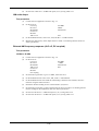
Introduction
The 3002 is a C size, message-based VXI signal generator covering the frequency range 9 kHz to
2.4 GHz. The RF output can be modulated in amplitude, frequency or phase using internal or
external signal sources. Additionally pulse modulation may be applied externally. An internal AF
source is capable of generating simultaneous two-tone modulation. The 3002 is 2 slots wide and
conforms to revisions 1.3 and 1.4 of the VXI specification.
Main features
Frequency selection
Carrier frequency resolution is 1 Hz across the band. A series of carrier frequencies can be stored
in non-volatile memory for recall when required.
Output
RF output up to +25 dBm (uncalibrated above 1.2 GHz) can be set with a resolution of 0.1 dB over
the entire range. Carrier output can be completely disabled.
An electronic trip protects the generator output against reverse power of up to 50 W. This prevents
damage to output circuits when RF or DC power is accidentally applied to the RF OUT connector.
To facilitate testing of receiver squelch systems, an attenuator hold function allows control of the
RF output without introducing RF level drop-outs from the step attenuator.
The RF output level can be offset by up to ± 5.0 dB to compensate for cable or switching losses, or
to standardize a group of instruments.
The maximum RF output level can be set so as to protect sensitive devices connected to the RF
OUTPUT socket.
Spectral purity
With an SSB phase noise performance of typically -121 dBc/Hz at 20 kHz offset from a 1 GHz
carrier, this instrument can be used for both in-channel and adjacent channel receiver
measurements. Harmonically related signals and non-harmonics are better than -25 dBc and
-60 dBc respectively.
Modulation
Comprehensive amplitude, frequency and phase modulations are available. Pulse modulation can
be applied to the carrier from an external pulse source. The instrument also accepts one or two
logic level inputs to produce a 2-level or 4-level FSK modulated output. An internal modulation
oscillator is provided, having a frequency range of 0.01 Hz to 20 kHz. The oscillator is capable of
generating one or two modulation tones simultaneously in one modulation channel. An
independent BNC input on the front panel allows external modulation signals to be combined with
1-1
GENERAL INFORMATION
the internal signal(s). These sources can be combined to give a number of modulation modes. The
pulse modulation can be used in combination with the other forms of modulation.
The frequency modulation range provides a 1 dB bandwidth of typically 100 kHz and provides FM
deviation up to a maximum of 100 kHz. AC or DC coupled FM can be selected. Phase
modulation is also available with a 10 kHz bandwidth up to a maximum of 10 radians.
Amplitude modulation with a 1 dB bandwidth of typically 30 kHz and with modulation depths of
up to 99.9% is available with a resolution of 0.1%. Pulse modulation is available as standard with
typical rise and fall times of less than 10 µs and 40 dB on/off ratio.
The external input voltage required for 100% modulation is 1 V RMS (1.414 V peak). To
accommodate other signal levels, Automatic Level Control (ALC) can be selected which provides
correctly calibrated modulation for inputs between 0.75 and 1.25 V RMS. HI and LO indications
are reported when the input level is outside the range of the ALC system.
Incrementing
All major parameters can be incremented or decremented in steps. If no step size is programmed
for a parameter, the steps are preset to 1 kHz for carrier frequency, 1 kHz for modulation oscillator,
1 kHz for FM deviation, 1% for AM depth, 0.1 rad for Φ M and 1 dB for output level.
Frequency sweep
The sweep capability of the instrument allows comprehensive testing of systems. Sweeps may be
logarithmic or linear. Four parameters are used to specify sweep: start, stop, step size and time per
step, all of which can be programmed by the user. Sweep triggering can be programmed as single
shot or continuous and can be initiated directly or on the detection of a trigger. The triggering
signal may be from a back plane trigger, programmed or from a TTL/CMOS signal applied to the
front panel TRIGGER INPUT.
Memory
The instrument provides both non-volatile and volatile memory for storing instrument settings.
The non-volatile memory provides 100 instrument settings and 100 settings of carrier frequency
only. The volatile memory (RAM) also provides 100 instrument settings. Any one of the nonvolatile instrument settings can be selected as the power-up setting for the instrument.
Memory sequencing
A software facility allows sequences of stored instrument settings to be defined. The incrementing
facilities can then be used to cycle through the settings using the VXI trigger facilities.
Memory protection
To prevent accidental change of the contents of the stored settings, individual memories or ranges
of memories can be write-protected.
Triggers
Triggering the 3002 Signal Generator may be via the VXI TTL triggers (0 - 7), the trigger
command, *TRG message or front panel input.
Calibration data
All alignment data is digitally derived. Realignment can be undertaken, without removing covers,
by protected functions via the VXI interface.
1-2
GENERAL
INFORMATION
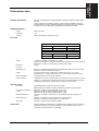
Performance data
GENERAL DESCRIPTION
The 3002 is a synthesized VXI signal generator covering the frequency range 9 kHz to
2.4 GHz.
The RF output can be amplitude, frequency, phase or pulse modulated. An internal
programmable AF source is capable of generating simultaneous two-tone modulation.
All functions can be controlled by an IEEE 488.2 message-based interface.
CARRIER FREQUENCY
Range
9 kHz to 2.4 GHz.
Resolution
1 Hz.
Accuracy
Equal to the frequency standard accuracy.
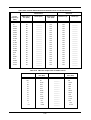
RF OUTPUT
Accuracy over temperature range 17°C to 27°C
9 kHz to 1.2 GHz
1.2 GHz to 2.4 GHz
±1.0 dB
±2.0 dB
>−127 dBm
±1.2 dB
Temperature coeff. over temperature range 0°C to 55°C
9 kHz to 1.2 GHz
1.2 GHz to 2.4 GHz
<±0.02 dB/°C
<±0.04 dB/°C
Range
-137 dBm to +25 dBm (+19 dBm above 1.2 GHz).
When AM is selected, the maximum RF output level decreases linearly with increasing
AM depths to +19 dBm (+13 dBm above 1.2 GHz) at 99% depth.
Resolution
0.1 dB
Accuracy
Attenuator hold
Selection of attenuator hold provides for uncalibrated level reduction of at least 10 dB
without the mechanical attenuator operating.
VSWR
For output levels less than -5 dBm output VSWR is less than 1.3:1 for carrier
frequencies up to 1.2 GHz and less than 1.5:1 for carrier frequencies up to 2.4 GHz.
Output impedance
50 Ω SMA female connector to MIL 390123D.
Output protection
Protected from a source of reverse power up to 50 W from 50 Ω or 25 W from a source
VSWR of 5:1. Tripping of the reverse power protection circuit illuminates a front panel
LED and raises an interrupt. The protection circuit can be reset remotely.
SPECTRAL PURITY
Harmonics
Typically better than -30 dBc for levels up to +7 dBm,
typically better than -25 dBc for levels 6 dB below the maximum specified output.
Non-harmonics (offsets >
3 kHz)
Better than -70 dBc for carrier frequencies up to 1 GHz,
better than -64 dBc for carrier frequencies above 1 GHz,
better than -60 dBc for carrier frequencies above 2 GHz.
Residual FM (FM off)
Less than 4.5 Hz RMS in a 300 Hz to 3.4 kHz bandwidth at a carrier frequency of
1 GHz.
SSB phase noise
Better than -124 dBc/Hz at 20 kHz offset from a 470 MHz carrier.
Typically -121 dBc/Hz at 20 kHz offset from a 1 GHz carrier.
ΦM on AM
Typically 0.1 radians at 30% depth at 470 MHz.
MODULATION
Internal and external modulation can be simultaneously enabled to produce combined
amplitude and frequency (or phase) modulation. Pulse modulation can be used in
combination with the other forms of modulation.
1-3
GENERAL INFORMATION
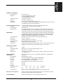
FREQUENCY MODULATION
Deviation range
0 to 100 kHz.
Resolution
3 digits or 1 Hz.
Accuracy
±5% at 1 kHz modulation rate.
Bandwidth (1 dB)
DC to 100 kHz (DC coupled),
10 Hz to 100 kHz (AC coupled),
20 Hz to 100 kHz (AC coupled with ALC).
Group delay:
Less than 5 µs to 100 kHz.
Carrier frequency offset
Less than 1% of the set frequency deviation when DC coupled.
Distortion
Less than 3% at 1 kHz rate for deviations up to 100 kHz.
Typically <0.5% at 1 kHz rate for deviations up to 10 kHz.
Modulation source
Internal LF generator or external via front-panel BNC.
Modes
2 level or 4 level FSK.
Note that 4 FSK is not available with Option 11 Fast Pulse fitted.
Data source
External data connected to TRIGGER INPUT connector (2 level) or TRIGGER INPUT
and PULSE INPUT connectors (4 level).
FSK
Frequency shift:
Settable up to ±100 kHz.
Accuracy
As FM deviation accuracy.
Timing jitter
±3.2 µs
Filter
8th order Bessel, −3 dB at 20 kHz.
PHASE MODULATION
Deviation
0 to 10 radians.
Resolution
3 digits or 0.01 radians.
Accuracy at 1 kHz
±5% of indicated deviation excluding residual phase modulation.
Bandwidth (3 dB)
100 Hz to 10 kHz.
Distortion
Less than 3% at 10 radians at 1 kHz modulation rate. Typically <0.5% for deviations up
to 1 radian at 1 kHz.
Modulation source
Internal LF generator or external via front-panel BNC.
AMPLITUDE MODULATION (for
carrier frequencies <500 MHz, usable
to 2 GHz)
Range
0 to 99.9%.
Resolution
0.1%.
Accuracy
±5% of set depth at 1 kHz rate at +17°C to 27°C ambient temperature.
Temperature coefficient <0.02% per °C.
Bandwidth (1 dB)
DC to 30 kHz (DC coupled),
10 Hz to 30 kHz (AC coupled),
20 Hz to 30 kHz (AC coupled with ALC).
Distortion
Less than 2.5% at 1 kHz rate for modulation depths up to 80%,
Less than 1.5% at 1 kHz rate for modulation depths up to 30%.
Modulation source
Internal LF generator or external via front-panel BNC.
PULSE MODULATION
Carrier frequency range
32 MHz to 2.4 GHz, usable to 10 MHz.
RF level range
Maximum guaranteed output is reduced to +20 dBm, +14 dBm above 1.2 GHz.
RF level accuracy
When pulse modulation is enabled, adds ±0.5 dB to the RF level accuracy.
Control
TTL/CMOS compatible pulse input is on front-panel BNC connector with 10 kΩ input
impedance.
A logical ‘1’ (3.5 V to 5 V) turns the carrier on, a logical ‘0’ (0 V to 1 V) turns the carrier
off. Maximum safe input is ±15 V.
ON/OFF ratio
Better than 45 dB below 1.2 GHz.
Better than 40 dB above 1.2 GHz.
Rise and fall time
Less than 10 µs.
1-4
GENERAL
INFORMATION
INTERNAL LF GENERATOR
Frequency range
0.01 Hz to 20 kHz.
Resolution
0.01 Hz for frequencies up to 100 Hz,
0.1 Hz for frequencies up to 1 kHz,
1 Hz for frequencies up to 20 kHz.
Frequency accuracy
As frequency standard.
Distortion
Less than 0.1% THD at 1 kHz.
Waveforms
Sine to 20 kHz, triangle or square wave to 3 kHz.
Audio output
The modulation oscillator signal is available on a front-panel BNC connector at a level of
2 V RMS EMF from a 600 Ω source impedance.
EXTERNAL MODULATION INPUT
A front panel BNC connector is provided for external modulation input.
Input level
1 V RMS (1.414 V peak) sine wave for set deviation.
Input impedance
100 kΩ nominal.
Modulation ALC
The external modulation input can be leveled by a peak leveling ALC system over the
input voltage range of 0.75 V to 1.25 V RMS sine wave. High and low indications are
reported as part of the instrument status when the input is outside the leveling range.
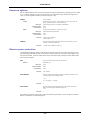
SWEEP MODE
Control parameters
A carrier frequency sweep mode is provided. The sweep is defined by setting the start,
stop and frequency step size. The step time can be set from. A step or the complete
sweep may be triggered by the trigger input on the front panel, VXI backplane trigger,
message or VXI command. Sweep can be set to continuous.
Start/stop values of carrier frequency, size of step and time per step.
Sweep time
50 ms to 10 s per step.
Linear sweep
Frequency step size of 1 Hz minimum.
Logarithmic sweep
Percentage increment of 0.01% to 50% in 0.01% steps.
Sweep mode
Single, continuous or external trigger.
Trigger mode
A trigger input is available on a front-panel BNC. A step or the complete sweep may be
triggered by the front-panel input, VXI backplane trigger or VXI command.
FREQUENCY STANDARD
TCXO
10 MHz.
Temperature stability
Better than ±7 in 10 over the operating range 0 to 55°C.
7
6
Aging rate
Less than ±1 in 10 per year.
External input
Front-panel BNC connector accepts an input of 1 MHz or 10 MHz at 220 mV RMS to
1.8 V RMS into 1 kΩ.
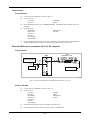
VXI-bus INTERFACE
CAPABILITIES
Logical address
Complies with revisions 1.3 and 1.4 of the VXIbus specification for message-based
instruments.
Manual selection (1 - 254).
Device type
A16 D16 message-based servant, programmable interrupter.
Protocol
Word serial IEEE 488.2. Fast handshake not supported.
Connectors
P1, P2 (highest slot of a 2-slot allocation).
TTLTRG
Used to trigger sweep mode and step memory sequences.
CLK10
Not used.
Local bus
Not used.
ECLTRG
Not used.
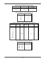
Peak current & power
consumption
Cooling (per slot)
Ipm
Idm
+24 V:
+12 V:
+5 V:
-12 V:
Total power:
1.2 A
0.1 A
1.0 A
0.1 A
2.0 A
1.3 A
0.6 A
0.1 A
60 W max.
2.4 litre/s at 1 mm H2O backpressure for 10°C maximum temperature rise.
BITE (built-in test equipment)
LEDs on module's front panel indicate POWER OK (green), SYSTEM FAIL (red) and
RPP TRIP - Reverse Power Protection Tripped (red).
RFI COMPATIBILITY
Complies with VXIbus revision 1.3/1.4 specifications below 1 GHz.
1-5
GENERAL INFORMATION
ELECTROMAGNETIC
COMPATIBILITY
Conforms with the protection requirements of the EEC Council Directive 89/336/EEC.
Conforms with the limits specified in the following standards:
IEC/EN61326-1 : 1997, RF Emission Class B,
Immunity Table 1, Performance Criterion B
SAFETY
Conforms with the requirements of EEC Council Directive 73/23/EEC (as amended) and
the product safety standard IEC/EN 61010-1 : 2001 + C1 : 2002 + C2 : 2003 for Class 3
portable equipment, for use in a Pollution Degree 2 environment. The instrument is
designed to operate from an Installation Category 1 supply.
RATED RANGE OF USE
Full specification is met over the temperature range 0 to +55°C, humidity up to 93% at
40°C and elevation up to 3050 m (10,000 ft).
CONDITIONS OF STORAGE AND
TRANSPORT
The instrument can be stored at temperatures from -40°C to +70°C, humidities up to
93% at 40°C, and elevations up to 4600 m (15,000 ft).
CALIBRATION INTERVAL
2 years.
DIMENSIONS AND WEIGHT
Dimensions
2 slot, C size.
Weight
Less than 4 kg.
Versions, options and accessories
When ordering please quote the full ordering number information.
Ordering numbers
Versions
3002
9 kHz to 2.4 GHz Signal Generator.
Option
Option 11
Fast pulse modulator.
Supplied accessories
46882/226
59000/285
59000/286
Operating manual (this manual).
LabWindows/CVI driver.
VXI Plug & Play soft front panel.
1-6
GENERAL
INFORMATION
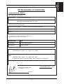
EC Declaration of Conformity
Certificate Ref. No.: DC230
The undersigned, representing:
Manufacturer:
Aeroflex International Ltd.
Address:
Longacres House, Six Hills Way,
Stevenage, Hertfordshire, UK SG1 2AN
Herewith declares that the product:
Equipment Description:
Model No.
3002
Options:
11
VXI 9 kHz to 2.4 GHz Signal Generator
is in conformity with the following EC directive(s)
(including all applicable amendments)
Title:
Reference No.
73/23/EEC
Low Voltage Directive
89/336/EEC
EMC Directive
and that the standards and/or technical specifications referenced below have been applied:
Safety:
IEC/EN61010-1 : 2001 + C1 : 2002 + C2 : 2003
EMC:
IEC/EN 61326-1:1997 + A1 : 1998 + A2 : 2001
RF Emission Class B, Immunity Table 1 and Performance Criterion B
Qualifying Notes:
Aeroflex Stevenage (Place)
(Signature)
Robert Trott — Director of Product Assurance
1-7
23 December 2003
(Date)
Chapter 2
INSTALLATION AND POWER-UP
Contents
Initial visual inspection................................................................................................................ 2-1
Setting logical address ................................................................................................................. 2-1
Ventilation requirements.............................................................................................................. 2-1
Installing in VXI mainframe ........................................................................................................ 2-2
Routine safety testing and inspection........................................................................................... 2-2
Cleaning....................................................................................................................................... 2-3
Putting into storage ...................................................................................................................... 2-3
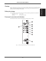
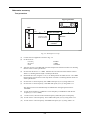
Front panel connectors and indicators ......................................................................................... 2-3
Switching on ................................................................................................................................ 2-4
Disk installation/loading instructions........................................................................................... 2-4
List of figures
Fig. 2-1 3002 front panel showing connectors and indicators .................................................... 2-3
WARNING
!
Initial visual inspection
After unpacking the equipment, inspect the shipping container and its cushioning material for signs
of stress or damage. If damage is identified, retain the packing material for examination by the
carrier in the event that a claim is made. Examine the equipment for signs of damage; do not
connect the equipment to a supply when damage is present, internal electrical damage could result
in shock if the equipment is turned on.
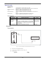
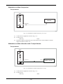
Setting logical address
Before installing the signal generator in the VXI mainframe, verify that the logical address is
between 1 and 254 and does not clash with the logical address of any other device in the rack. The
logical address is set on a bank of 8 DIL switches. These are located on the right-hand side of the
instrument. Use some form of stylus (e.g. a ball-point pen) to move the switches to form the binary
address. Logical addresses may be set in the range 1 to 254. Logical address 0 is reserved for slot
0 devices and logical address 255 is reserved for dynamically configured devices. The 3002 VXI
Signal Generator does not support dynamic configuration.
Ventilation requirements
Ensure that the VXI signal generator module is supplied with adequate cooling i.e. 2.4 liter/s at
1 mm H2O backpressure minimum per slot.
2-1
INSTALLATION AND POWER-UP
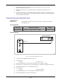
Installing in VXI mainframe
This instrument will take up two slots of a C-sized VXI mainframe. Before installation ensure that
the mainframe power is off. To install the instrument first set the logical address (see ‘Setting
logical address’ above), if required, then slide the module into the mainframe ensuring that the top
and bottom card guides are in the slots. Ensure that the rear connectors are seated properly and
screw in the front panel retaining screws. The instrument is now ready to power up.
Never insert or remove the instrument when the mainframe is already powered up.
Routine safety testing and inspection
1. Visual inspection
In the UK the 'Electricity at Work Regulations' (1989) section 4(2) places a requirement on the
users of equipment to maintain it in a safe condition. The explanatory notes call for regular
inspections and tests together with a need to keep records.
This module is not designed to be connected to a supply or signals which present hazardous levels,
and no hazardous voltages are generated internally. All such levels must be maintained within
'Separated Extra-Low Voltage' (SELV or SELV-E) limits for continued safety. No requirement
therefore exists to carry out insulation tests on the module. Periodic electrical tests and visual
inspections should however be performed on the complete mainframe/chassis by competent
personnel. Information should be sought from the mainframe supplier regarding the visual
inspection, earth bonding and insulation resistance test requirements.
Visually check that the module has been installed in accordance with the instructions provided (e.g.
that the ventilation is adequate, all fixing screws are present and tightened, and that all warning
labels, markings and supplied safety information are present and legible). If any defect is noted
this should be rectified before proceeding with further electrical tests.
No attempt should be made to perform high current earth bonding tests on the functional earths
(e.g. signal carrying connector shells or screen connections) present on the module connectors.
High current earth bonding tests are also not recommended between the mainframe protective earth
connector and the module front panel. Serious damage may result to both the module and the
mainframe if the module is not fully screwed into the mainframe during high current testing. Low
current earth bonding tests (1 mA to 100 mA) should be performed to establish earth path
continuity between the module front panel and the mainframe protective earth.
2. Rectification
It is recommended that the results of the above tests are recorded and checked during each repeat
test. Significant differences between the previous readings and measured values should be
investigated.
If any failure is detected during the above visual inspection or tests, the equipment should be
disabled and the fault should be rectified by an experienced Service Engineer who is familiar with
the hazards involved in carrying out such repairs.
Safety critical components should only be replaced with equivalent parts, using techniques and
procedures recommended by Aeroflex.
The above information is provided for guidance only. Aeroflex designs and constructs its products
in accordance with International Safety Standards such that in normal use they represent no hazard
to the operator. Aeroflex reserves the right to amend the above information in the course of its
continuing commitment to product safety.
2-2
INSTALLATION AND POWER-UP
Before commencing any cleaning, switch off the instrument and disconnect the mainframe from the
supply. The exterior surface of the case may be cleaned using a soft cloth moistened in water.
Do not use aerosol or liquid solvent cleaners.
Putting into storage
If the instrument is to be put into storage, ensure that the following conditions are maintained:
Temperature range:
Humidity:
−40 to +70°C
Less than 93% at 40°C
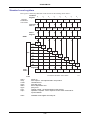
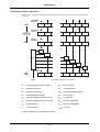
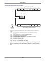
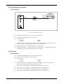
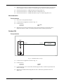
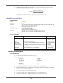
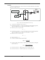
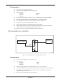
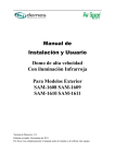
Front panel connectors and indicators
The front panel with its connectors and indicators is shown in Fig. 2-1 below:
Fig. 2-1 3002 front panel showing connectors and indicators
2-3
INSTALLATION
Cleaning
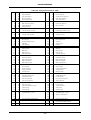
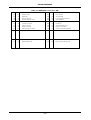
INSTALLATION AND POWER-UP
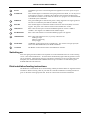
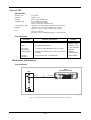
1
RF OUT
50 Ω SMA-type socket. Protected against the application of reverse power of up to
50 W.
2
SYSTEM FAIL
This red LED lights to indicate that the signal generator has failed, or is in the process
of executing its self-test. It indicates the condition of the VXI-bus SYSFAIL line.
The LED will continue to be lit whilst the self-test is in progress even when SYSFAIL
is inhibited by the commander.
3
POWER OK
This green LED lights to indicate that power is being supplied to the signal generator.
All lines are continuously checked for sufficient voltage.
4
RPP TRIP
This red LED lights to indicate that the Reverse Power Protection (RPP) circuit has
tripped. The power source must be removed from the RF OUT socket.
5
FREQ STD I/O
BNC socket for the input of external standard frequencies of either 1 MHz or
10 MHz. Also supplies a 10 MHz internal standard output.
6
EXT MOD INPUT
BNC socket which allows an external modulating signal to be applied.
7
TRIGGER INPUT
BNC socket which has three uses; in priority order these are:
FSK logic input
Memory sequencing
Sweep trigger.
8
PULSE INPUT
10 kΩ BNC socket which accepts a pulsed input. Also used as one logic input (the
other is the TRIGGER INPUT) for 4FSK modulation.
9
LF OUTPUT
600 Ω BNC socket which monitors the modulation oscillator.
Switching on
Insert the signal generator module in the required slot in the mainframe and screw in the retaining
screws. Switch the mainframe on. All three LEDs should initially light while the generator carries
out its self checks. When the unit passes its self checks, and if there are no errors detected on the
backplane, the red SYSTEM FAIL and RPP LEDs will go out within 5 seconds and the green
POWER OK LED will remain on.
Disk installation/loading instructions
LabWindows/CVI Instrument Driver and VXI Plug and Play Soft Panel disks are supplied with this
instrument. Before inserting a disk in your disk drive read the installation or loading instructions
given on the label of the appropriate disk. Refer to 'read me' files for further information.
2-4
Chapter 3
PROGRAMMING
Introduction
An IEEE 488.2 program interface is provided. Ease of use is ensured by careful selection of
mnemonics. For example, if carrier frequency and RF level are to be set to 2.54 MHz and
-27.3 dBm respectively, the VXI instruction message is:
CFRQ:VALUE 2.54 MHZ<EOM>
RFLV:VALUE -27.3 DBM<EOM>
For full information on the IEEE protocols and syntax the IEEE 488.2 standard should be
consulted.
Device listening elements
The following is a list of the device listening elements (as defined in the IEEE 488.2 standard)
which are used in the instrument:
<PROGRAM MESSAGE>
<PROGRAM MESSAGE TERMINATOR>
<PROGRAM MESSAGE UNIT>
<PROGRAM MESSAGE UNIT SEPARATOR>
<COMMAND MESSAGE UNIT>
<QUERY MESSAGE UNIT>
<COMPOUND COMMAND PROGRAM HEADER>
<COMPOUND QUERY PROGRAM HEADER>
<PROGRAM HEADER SEPARATOR>
<PROGRAM DATA>
<PROGRAM DATA SEPARATOR>
<DECIMAL NUMERIC PROGRAM DATA>
<CHARACTER PROGRAM DATA>
<SUFFIX PROGRAM DATA>
<STRING PROGRAM DATA>
<ARBITRARY BLOCK PROGRAM DATA>
Device talking elements
The following is a list of the device talking elements (as defined in the IEEE 488.2 standard) which
are used in the instrument:
<RESPONSE MESSAGE>
<RESPONSE MESSAGE TERMINATOR>
<RESPONSE MESSAGE UNIT>
<RESPONSE MESSAGE UNIT SEPARATOR>
<COMPOUND RESPONSE HEADER>
<RESPONSE HEADER SEPARATOR>
<RESPONSE DATA>
<RESPONSE DATA SEPARATOR>
<NR1 NUMERIC RESPONSE DATA>
<NR2 NUMERIC RESPONSE DATA>
<ARBITRARY ASCII RESPONSE DATA>
<CHARACTER RESPONSE DATA>
<STRING RESPONSE DATA>
<DEFINITE LENGTH ARBITRARY BLOCK RESPONSE DATA>
3-1
Programming
Program messages
A message consists of one or more message units. Message units are separated by a semi-colon (;). The
whole message is ended by the Program Message Terminator (or End Of Message) defined as one
of the following:
(1)
<newline> (ASCII 10 - often known as 'line feed') or
(2)
<newline> + END (the EOI line is asserted as well) or
(3)
+ END (EOI is asserted in the last data byte of the message)
A response message is always terminated by <EOM> consisting of <newline> + END.
A message unit consists of a mnemonic header which may be followed by data. If data follows,
then it must be separated from its header by at least one space:
<header><SPACE><data>
e.g. RFLV:INC 6.0 dB
Spaces may be freely inserted in a message to improve readability, except within a header or within
data.
A header may be a command or a query. A query has a '?' as its final character and causes the
generation of a response message which will be read by the controller. Common commands and
queries (defined in IEEE 488.2) begin with a '*'.
Upper and lower case characters are considered equivalent (i.e. FM fm Fm fM are all interpreted
by the instrument in the same way).
Compound headers
The instrument implements compound headers which allows a complex set of commands to be
built up from a small set of basic elements in a 'tree and branch' structure. The elements of a
compound header are separated by a colon (:). Spaces are not allowed within a header.
Special rules apply when more than one compound header is used in one message. When the
separator ';' is encountered, all headers except the trailing element of the previous header in the
message are assumed to precede the following header, for example:
AM:DEPTH 30PCT;ON
is equivalent to the two commands:
AM:DEPTH 30PCT
and AM:ON
This does not apply to common commands (*RST etc.). The rule may be overridden by preceding
a header with a colon, for example:
AM:ON;:FM:ON
Most main functions have a short form of header which may be used for clarity and brevity in
simple messages, for example:
CFRQ 1.25GHZ is the same as CFRQ:VALUE 1.25GHZ
3-2
Program data
Data can take many forms, as follows:
Decimal Numeric Data is a flexible numeric format which encompasses integer, fixed point and
floating point (mantissa and exponent) representations. Data is rounded to a resolution appropriate
to the function. Decimal data can, in most cases, be followed by the appropriate units. If no units
are present, the specified default units are assumed.
Character Data is an alphanumeric word.
String Data consists of a number of 7-bit ASCII characters enclosed in quotes, either a pair of
single ('ASCII 39') or double ("ASCII 34") quotes may be used.
Some commands can accept Multiple Data items which are separated by commas, for example
MODE FM,AM.
Message exchange protocol
The controller should not attempt to read a response until it has sent the entire query message
(terminated by EOM). Also, it should not start to send a new message until it has read the entire
response (terminated by EOM). The query message may contain more than one query message
unit, but only one response message (containing several response message units) is generated.
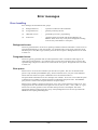
Failure to follow the protocol will generate a query error:
INTERRUPTED (error 450) occurs when the controller starts to send a new message before having
read the response to a preceding query.
UNTERMINATED (error 451) occurs when the controller attempts to read a response without
having sent a query.
DEADLOCK (error 452) can only occur if the input and output buffers are both filled by the
controller having sent an extra long message containing several query message units.
These instruments have an input buffer of 256 characters and an output buffer of 256 characters.
Common commands and queries (IEEE 488.2)
The IEEE 488.2 standard defines a set of common commands and queries which implement
common system functions.
Common command and query mnemonics are preceded by an asterisk (*) to distinguish them from
device dependent data such as instrument programming strings. The following common commands
and queries are implemented in the instrument:
Mnemonic
Name and Description
*IDN?
Identification Query. Returns an arbitrary ASCII response comprising four data
fields in the format:
<manufacturer>,<model>,<serial number>,<software part number and issue number>
where: <manufacturer> is IFR ,<model> is the instrument model number, 3002.
<serial number> is the instrument serial number in the form nnnnnn/nnn, where
n is an ASCII digit in the range 0 to 9.
<software part number and issue number> is in the form nnnnn/nnn/n.nn, where
n is an ASCII digit in the range 0 to 9.
Example:
*OPT?
IFR,3002,811152/011,44533/445/01.00<EOM>
Option Identification Query. Returns an arbitrary ASCII response containing a data
field for each fitted option in the format:
<option a>,<option b>, ... ,<option n><EOM>
If no options are fitted, ASCII '0' is returned.
Because an Arbitrary ASCII Response ends with the Response Message Terminator
(<EOM>) either *IDN? or *OPT? must be the last Query Message Unit in a Program
Message.
3-3
*RST
Reset Command. Sets the instrument functions to the factory default power up
state.
*TST?
Self Test Query. Returns a '0' when the VXI interface and processor are operating.
*OPC
Operation Complete Command. Sets the Operation Complete bit in the Standard
Event Status Register when execution of the preceding operation is complete.
*OPC?
Operation Complete Query. Returns a '1' when the preceding operation has been
completed.
*WAI
Wait to Continue Command. Inhibits execution of an overlapped command until
the execution of the preceding operation has been completed.
*TRG
Trigger Command. Equivalent to Group Execute Trigger.
*STB?
Read Status Byte Query. Returns the value of the Status Byte as an nr1 number (0255).
*SRE <nrf>
Service Request Enable Command. Sets the Service Request Enable Register.
*SRE?
Service Request Enable Query. Returns the value of the Service Request Enable
Register as nr1.
*ESR?
Standard Event Status Register Query. Returns the value of the Status Event Status
Register as nr1.
*ESE <nrf>
Standard Event Status Enable Command. Sets the Standard Event Enable Register.
*ESE?
Standard Event Status Enable Query. Returns the value of the Standard Event
Status Enable Register as nr1.
*CLS
Clear Status Command. Clears all the Status Event registers and clears the Error
Queue. Does not affect the Enable Registers.
The IEEE 488.2 Device Clear function only affects the remote functions. The input and
output buffers are cleared and the instrument put into a state to accept new messages.
Earlier versions of IEEE 488.1 put the instrument functions into a defined state, but this is
now performed by the *RST common command.
Device dependent commands
The following list describes the features of the device dependent mnemonics for the instrument
together with simple examples of their use within each major section (Carrier frequency, RF level,
etc.) The root mnemonic is listed first followed by the lower level mnemonics. Each group is
followed by a list of requirements for data type and suffix.
In addition to the normal listen commands the instrument accepts query commands which cause it
to prepare a message which will be sent to the controller when the instrument is next addressed to
talk. For each query an example of a response is given. Where responses are similar for a group of
queries not all are listed. Some queries can produce more than one type of response - an example
of each is usually given.
In the list which follows, the abbreviations <char>, <nrf> and <str> have the following meanings:
<char>
=
Character Program Data
<nrf>
=
Decimal Numeric Program Data
<str>
=
String Program Data
Where the data format is Decimal Numeric Program Data, the value may be expressed as a signed
or unsigned number in any of the following formats:
nr1:
Decimal integer, e.g. 1234 or -567
nr2:
Floating point number, e.g. 1.234 or -56.789
nr3:
Floating point number with exponent, e.g. 1.2345E5 or -12.47E-8
3-4
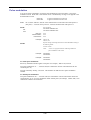
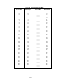
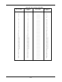
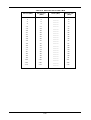
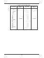
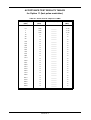
Default settings
The instrument is reset to the factory default settings in the following cases:
(1) At power-up.
(2) Following execution of the RCL 999 command.
(3) Following execution of the *RST command.
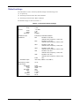
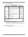
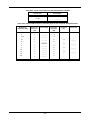
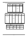
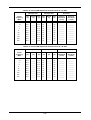
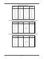
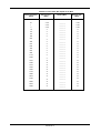
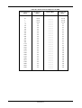
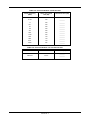
The default settings are shown in Table 3-1 .
Table 3-1 Instrument default settings
Carrier frequency
:
Step :
2.4 GHz
1 kHz
RF level
−137 dBm
1 dB
ON
Enabled
Step :
Status:
RF output :
Modulation mode
Modulations
Internal FM, modulation disabled
:
Modulation steps :
FM1
:
:
Deviation: 0 Hz, OFF
Internal source, frequency: 1 kHz, sine
FM2
:
:
Deviation: 0 Hz, OFF
Internal source, frequency: 400 Hz, sine
ΦM1
:
:
Deviation: 0 rad, OFF
Internal source, frequency: 1 kHz, sine
ΦM2
:
:
Deviation: 0 rad, OFF
Internal source, frequency: 400 Hz, sine
AM1
:
:
Deviation: 0%, OFF
Internal source, frequency: 1 kHz, sine
AM2
:
:
Deviation: 0%, OFF
Internal source, frequency: 400 Hz, sine
Pulse
:
OFF
∆FM 1 kHz, ∆ΦM 0.1 rad, ∆AM 1%
Mod frequency steps :
10 Hz
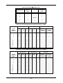
Carrier sweep
Freq mode:
Mode :
Type:
Ext trigger :
Start :
Stop:
Step size:
Time:
Fixed
Single sweep
Linear
OFF
9 kHz
2.4 GHz
1 kHz
50 ms
3-5
Carrier frequency
These commands enable you to set the carrier frequency in the range 9 kHz to 2.4 GHz to a
resolution of 1 Hz. You can adjust the frequency in steps by setting the size of the step and then
stepping the frequency up or down. After having adjusted the frequency you can either return to
the reference frequency or make the current frequency the reference frequency. Additionally, you
can adjust the phase offset of the carrier in degrees in the range -359.99° to +359.99°. Also you
can configure the instrument as a swept frequency signal generator where you define the start and
stop frequencies and set the step size, step time and step direction. For triggering methods, refer to
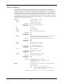
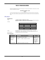
'Trigger source' at the end of this section.
Set Carrier Frequency (short form)
CFRQ
:VALUE
Set Carrier Frequency
:INC
Set Carrier Frequency step size
Data type :
Allowed suffices :
Default suffix :
Decimal Numeric Program Data
Any one of: GHZ, MHZ, KHZ or HZ
HZ
:UP
Go UP one step
:DN
Go DOWN one step
:RETN
Return to original setting
:XFER
Transfer current value to be the new setting
Data type :
Allowed suffices :
Default suffix :
None
None
None
Selects the mode of carrier frequency operation. SWEPT enables swept
carrier frequency operation, while FIXED disables it
:MODE
Data type :
Allowed suffices :
Default suffix :
Character Program Data (FIXED - non swept mode, SWEPT - swept
mode)
None
None
:START
Set Start Frequency for use in sweep
:STOP
Set Stop Frequency for use in sweep
Data type :
Allowed suffices :
Default suffix :
Decimal Numeric Program Data
Any one of: GHZ, MHZ, KHZ or HZ
HZ
Set time per sweep step
:TIME
Data type :
Allowed suffices :
Default suffix :
Decimal Numeric Program Data
MS or S
MS
Adjust Phase Offset of Carrier in degrees
:PHASE
Data type :
Allowed suffices :
Default suffix :
Examples:
Decimal Numeric Program Data
DEG
DEG
CFRQ:VALUE 2.54MHZ;INC 10KHZ
CFRQ:UP;XFER
CFRQ:START 1MHZ;STOP 10MHZ;TIME 100MS
CFRQ:MODE SWEPT
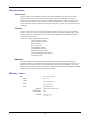
Prepares message containing information on Carrier Frequency setting
in the following format:
CFRQ?
:CFRQ:VALUE <nr2>; INC <nr2>;MODE<mode>
where:
Example:
<mode> is character program data indicating whether carrier
frequency operation is swept or fixed
:CFRQ:VALUE 1000000000.0;INC 25000.0;MODE FIXED
3-6
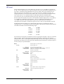
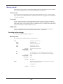
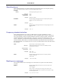
RF level
These commands enable you to set the RF level in the range -137 to +25 dBm to a resolution of
0.1 dB. You can adjust the level in steps by setting the size of the step and then stepping the level
up or down. And after having adjusted the level you can either return to the reference level or
make the current level the reference level. You can set the units to a default if required. For
voltage related units, you can select either EMF or PD. You can also switch the output at the RF
OUT socket off or on. For attenuator hold see under 'Miscellaneous commands' below.
You can also set your own maximum output power limit which allows you to protect sensitive
devices connected to the RF OUT socket. The maximum calibrated output level is +25.1 dBm up
to 1.2 GHz and +19 dBm above this frequency. Above 1.2 GHz an uncalibrated level up to
+25.1 dBm is allowed. The setting will be saved in non-volatile memory so that when
subsequently the instrument is switched on again it will be set with your specified RF level limit.
The RF offset function enables you to offset the RF output level to compensate for cable or
switching losses, or to standardize a group of instruments so that they give identical measurements.
One offset is allowed in each of the following ranges:
9 kHz
-
150 MHz
150 MHz
-
300 MHz
300 MHz
-
600 MHz
600 MHz
-
1.2 GHz
1.2 GHz
-
2.4 GHz
The entered carrier frequency automatically selects the appropriate frequency range over which the
offset is applied. Set the required positive or negative RF offset in the range 0 to 5.0 dB to a
resolution of 0.1 dB. For each required additional range enter the carrier frequency then the offset.
Ensure that your offsets are saved so that when subsequently the instrument is switched on again it
will be set with your specified offsets.
Set RF Output Level (short form)
RFLV
Set RF Output Level
:VALUE
Data type :
Allowed suffices :
Default suffix :
Decimal Numeric Program Data
Any one of: DBM, DBV, DBMV, DBUV, V, MV or UV
DBM unless changed by UNITS command
Set RF Level step (dB)
:INC
Data type :
Allowed suffices :
Default suffix :
Decimal Numeric Program Data
DB only
DB
:UP
Go UP one step
:DN
Go DOWN one step
:RETN
Return to original setting
:XFER
Transfer current value to be the new setting
:ON
Turn RF Output ON
:OFF
Turn RF Output OFF
Data type :
Allowed suffices :
Default suffix :
None
None
None
Selects EMF or PD for voltage related units
:TYPE
Data type :
Allowed suffices :
Default suffix :
Character Program Data (EMF or PD)
None
None
3-7
:UNITS
Select default RF level units.
Data type :
Allowed suffices :
Default suffix :
Examples:
Character Program Data (DBM, DBV, DBMV, DBUV, V, MV or UV)
None
None
RFLV:VALUE -27.3DBM;ON
RFLV:TYPE PD;VALUE 1.23UV
Set RF Level max limit (short form)
:LIMIT
:VALUE
Set RF Level max limit
Data type :
Allowed suffices :
Default suffix :
:ENABLE
Decimal Numeric Program Data
Any one of: DBM, DBV, DBMV, DBUV, V, MV or UV
DBM unless changed by UNITS command
Enable limit
:DISABLE
Disable limit
Set RF Level offset for given frequency band (short form)
:OFFS
:VALUE
Set RF Level offset for given frequency band
Data type :
Allowed suffices :
Default suffix :
Decimal Numeric Program Data
DB only
DB
:ENABLE
Enable offsets
:DISABLE
Disable offsets
:SAVE
Save offsets in non-volatile memory
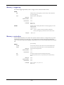
Prepares message containing information on RF Level setting in the
following format:
RFLV?
:RFLV:UNITS <unit>;TYPE <type>;VALUE <nr2>;INC <nr2>;<status>
where:
Examples:
<unit> is character program data defining the default RF
level units (DBM, DBV, DBMV, DBUV, V, MV or UV),
<type> is character program data indicating EMF or PD and
<status> is a program mnemonic indicating whether the RF
output is ON or OFF
:RFLV:UNITS DBM;TYPE PD;VALUE -103.5;INC 2.0;ON
:RFLV:UNITS DBV;TYPE EMF;VALUE -83.2;INC 0.5;ON
Prepares message containing information on RF Level max limit setting
in the following format:
RFLV:LIMIT?
:RFLV:LIMIT:VALUE<nr2>;<status>;
Examples:
:RFLV:LIMIT:VALUE-20.0;ENABLE
Prepares message containing information on RF Level offset in the
following format:
RFLV:OFFS?
:RFLV:OFFS:VALUE<nr2>;<status>;
Examples:
:RFLV:OFFS:VALUE-3.2;ENABLE
3-8
Output control
These commands allow you to download and store settings without the output changing.
[not used alone]
OUTPUT
:DISABLE
Allows user to download and store settings in the normal way without
the output of the instrument changing until the OUTPUT:ENABLE
command is received.
:ENABLE
Enables the instrument outputs such that the outputs will adjust to the
values specified by commands sent while the outputs were disabled.
Note: It is up to the user to ensure that the last command sent, prior to
OUTPUT:ENABLE, is such that the RF output is set to a safe
level.
Data type :
Allowed suffices :
Default suffix :
Examples:
None
None
None
OUTPUT:DISABLE
CFRQ 300MHZ; RFLV 10DBM; MODE AM; AM 40PCT;
AM:ON; MOD:ON; STO 200
CFRQ 400MHZ; RFLV 7DBM; STO 201
CFRQ 500MHZ; RFLV 5DBM; STO 202
CFRQ 600MHZ; RFLV 4DBM; STO 203
OUTPUT;ENABLE
RCL 200
RCL 201
RCL 202
RCL 203
Prepares message containing information on output control setting in
the following format:
OUTPUT?
: OUTPUT: <status>
where:
Examples:
<status> is a program mnemonic indicating whether the
output control is ENABLED or DISABLED
:OUTPUT:ENABLE
:OUTPUT:DISABLE
3-9
Modulation mode
These commands allow you to select the modulation mode between amplitude, frequency and
phase modulation as well as binary (2-level) and quadrature (4-level) frequency shift keying.
Binary FSK results from a logic level digital signal applied to the TRIGGER INPUT socket.
Quadrature FSK is achieved using both the TRIGGER INPUT and PULSE INPUT sockets. Also
pulse modulation may be selected from a signal connected to the PULSE INPUT socket. These
modulations may be used in the combinations shown in the table below. Additionally, an external
signal applied to the EXT MOD INPUT socket can be combined with any selected modulation
combination.
Set modulation mode
MODE
Data type :
Allowed suffices :
Default suffix :
Examples:
Character Program Data (valid combinations of AM, FM, PM, FSK2L,
FSK4L or PULSE. See table below.)
None
None
MODE AM,FM
MODE FM,PULSE
VALID MODE COMBINATIONS TABLE
AM [,PULSE]
FM [,PULSE]
PM [,PULSE]
AM,FM [,PULSE]
AM,PM [,PULSE]
FSK2L [,PULSE]
FSK4L
Note...
Order is not important, for example AM,FM is equivalent to
FM,AM. PULSE modulation can be used with any of the
AM,FM,PM and FSK2L modes, but not with FSK4L.
FSK2L and FSK4L parameters are controlled using the FM
commands. The frequency shifts produced by the applied data
are as follows:
2FSK
4FSK
TRIGGER
SHIFT
TRIGGER
PULSE
1
+D
1
0
SHIFT
+D
0
−D
1
1
+D/3
0
1
−D/3
0
0
−D
Where D is the set deviation value.
MODE?
Prepares message containing information on Modulation Mode in the
following format:
:MODE <mode>
where:
Example:
<mode> is character program data indicating the modulation
mode settings
:MODE AM,FM
3-10
Modulation control
These commands allow you to switch ALL modulation ON or OFF.
[not used alone]
MOD
:ON
Turn modulation globally ON
:OFF
Turn modulation globally OFF
Examples:
MOD?
MOD:ON
MOD:OFF
Prepares message containing information on Modulation Control in the
following format:
:MOD:<status>
where:
Example:
:MOD:ON
3-11
<status> is a program mnemonic indicating whether the
Modulation is globally ON or OFF
Frequency modulation (and FSK)
These commands enable you to select frequency modulation either as a single modulation or as the
sum of two signals, to set the deviation rate, to switch the modulation on and off and to perform DC
FM nulling. (For the latter, ensure that a ground reference is connected to the EXT MOD INPUT
socket before you implement the command.) You can set the modulation oscillator frequency and
select between sine, triangle and square waveforms. Also the phase difference of modulation
oscillator channel 2 relative to channel 1 can be offset in degrees. Both deviation rate and
modulation oscillator frequency can have their step sizes set and then be stepped up or down. And
after having adjusted the deviation rate or the modulation oscillator frequency you can either return
to the reference (rate or frequency) or make the current value the new reference.
Set FM Deviation (short form)
FM or FM1 or FM2
:DEVN
Set FM Deviation
:INC
Set FM step size
Data type :
Allowed suffices :
Default suffix :
Decimal Numeric Program Data
Any one of: GHZ, MHZ, KHZ or HZ
HZ
:<src>
Select modulation source where <src> is any one of: INT, EXTAC,
EXTALC, or EXTDC
:ON
Turn FM ON (locally)
:OFF
Turn FM OFF (locally)
:UP
Go UP one step
:DN
Go DOWN one step
:RETN
Return to original setting
:XFER
Transfer current value to be the new setting
Data type :
Allowed suffices :
Default suffix :
Examples:
:MODF
None
None
None
FM:DEVN 25KHZ;INT;ON
FM1:DEVN 15KHZ;INC 1KHZ;EXTDC
Set FM modulation oscillator frequency (short form)
:VALUE
Set FM modulation oscillator frequency
:INC
Set FM modulation oscillator frequency step size
Data type :
Allowed suffices :
Default suffix :
Decimal Numeric Program Data
Any one of: GHZ, MHZ, KHZ or HZ
HZ
:UP
Go UP one step
:DN
Go DOWN one step
:RETN
Return to original setting
:XFER
Transfer current value to be the new setting
:SIN
Select sinusoidal waveform
:TRI
Select triangle waveform
:SQR
Select square waveform
Data type :
Allowed suffices :
Default suffix :
None
None
None
3-12
:PHASE
Set phase offset of FM2 relative to FM1
Data type :
Allowed suffices :
Default suffix :
Examples:
Decimal Numeric Program Data
DEG
DEG
FM2:MODF:VALUE 1.5KHZ;SIN
FM:MODF:PHASE 1.2DEG
Perform DC FM null operation (only for EXTDC mode)
DCFMNL
Data type :
Allowed suffices :
Default suffix :
Example:
None
None
None
DCFMNL
Prepares message containing information on FM setting in one of the
following formats:
FM? or FM1? or FM2?
:FM:DEVN <nr2>;<src>;<status>;INC <nr2>
:FM1:DEVN <nr2>;<src>;<status>;INC <nr2>
:FM2:DEVN <nr2>;<src>;<status>;INC <nr2>
where:
<src> is a program mnemonic representing the source of the
modulation signal and <status> is a program mnemonic indicating
whether the frequency modulation is locally ON or OFF
Example:
:FM1:DEVN 25000.0;INT;ON;INC 1000.0
Prepares message containing information on FM modulation oscillator
setting in one of the following formats:
FM:MODF? or FM1:MODF?
or FM2:MODF?
:FM:MODF:VALUE <nr2>;<shape>;INC <nr2>
:FM1:MODF:VALUE <nr2>;<shape>;INC <nr2>
:FM2:MODF:VALUE <nr2>;<shape>;INC <nr2>
where:
Example:
<shape> is a program mnemonic representing the waveform
shape
:FM1:MODF:VALUE 5750.00;SIN;INC 1000.00
3-13
Phase modulation
These commands enable you to select phase modulation either as a single modulation or as the sum
of two signals, to set the deviation rate in radians, and to switch the modulation on and off. You
can set the modulation oscillator frequency and select between sine, triangle and square waveforms.
Also the phase difference of modulation oscillator channel 2 relative to channel 1 can be offset in
degrees. Both deviation rate and modulation oscillator frequency can have their step sizes set and
then be stepped up or down. And after having adjusted the deviation rate or the modulation
oscillator frequency you can either return to the reference (rate or frequency) or make the current
value the new reference.
Set Phase Modulation Deviation (short form)
PM or PM1 or PM2
:DEVN
Set Phase Modulation Deviation
:INC
Set Phase Modulation step size
Data type :
Allowed suffix :
Decimal Numeric Program Data
RAD
:<src>
Select modulation source where <src> is any one of: INT, EXTAC,
EXTALC, or EXTDC
:ON
Turn PM ON (locally)
:OFF
Turn PM OFF (locally)
:UP
Go UP one step
:DN
Go DOWN one step
:RETN
Return to original setting
:XFER
Transfer current value to be the new setting
Data type :
Allowed suffices :
Default suffix :
Examples:
:MODF
None
None
None
PM:DEVN 2.38RAD;INT;ON
PM1:DEVN 1.5RAD;INC 0.1RAD;EXTAC
Set PM modulation oscillator frequency (short form)
:VALUE
Set PM modulation oscillator frequency
:INC
Set PM modulation oscillator frequency step size
Data type :
Allowed suffices :
Default suffix :
Decimal Numeric Program Data
Any one of: GHZ, MHZ, KHZ or HZ
HZ
:UP
Go UP one step
:DN
Go DOWN one step
:RETN
Return to original setting
:XFER
Transfer current value to be the new setting
:SIN
Select sinusoidal waveform
:TRI
Select triangle waveform
:SQR
Select square waveform
Data type :
Allowed suffices :
Default suffix :
:PHASE
None
None
None
Set phase offset of PM2 relative to PM1
Examples:
PM1:MODF:VALUE 10.5KHZ;SQR
PM2:MODF:PHASE 2.0DEG
3-14
Prepares message containing information on Phase Modulation setting
in one of the following formats:
PM? or PM1? or PM2?
:PM:DEVN <nr2>;<src>;<status>;INC <nr2>
:PM1:DEVN <nr2>;<src>;<status>;INC <nr2>
:PM2:DEVN <nr2>;<src>;<status>;INC <nr2>
where
Example:
<src> is a program mnemonic representing the source of the
modulation signal and <status> is a program mnemonic
indicating whether the phase modulation is locally ON or
OFF
:PM2:DEVN 2.30;INT;OFF;INC 0.05
Prepares message containing information on PM modulation oscillator
setting in one of the following formats:
PM:MODF? or PM1:MODF?
or PM2:MODF?
:PM:MODF:VALUE <nr2>;<shape>;INC <nr2>
:PM1:MODF:VALUE <nr2>;<shape>;INC <nr2>
:PM2:MODF:VALUE <nr2>;<shape>;INC <nr2>
where:
Example:
<shape> is a program mnemonic representing the waveform
shape.
:PM2:MODF:VALUE 2500.00;TRI;INC 500.00
3-15
Amplitude modulation
These commands enable you to select amplitude modulation either as a single modulation or as the
sum of two signals, to set the AM depth as a percentage, and to switch the modulation on and off.
You can set the modulation oscillator frequency and select between sine, triangle and square
waveforms. Also the phase difference of modulation oscillator channel 2 relative to channel 1 can
be offset in degrees to a resolution of 0.1°. Both modulation depth and modulation oscillator
frequency can have their step sizes set and then be stepped up or down. And after having adjusted
the modulation depth or the modulation oscillator frequency you can either return to the reference
(depth or frequency) or make the current value the new reference.
Set AM Depth (short form)
AM or AM1 or AM2
:DEPTH
Set AM Depth
:INC
Set AM step size
Data type :
Allowed suffices :
Default suffix :
Decimal Numeric Program Data
PCT
PCT
:<src>
Select modulation source where <src> is any one of: INT, EXTAC,
EXTALC, or EXTDC
:ON
Turn AM ON (locally)
:OFF
Turn AM OFF (locally)
:UP
Go UP one step
:DN
Go DOWN one step
:RETN
Return to original setting
:XFER
Transfer current value to be the new setting
Data type :
Allowed suffices :
Default suffix :
Examples:
None
None
None
AM:DEPTH 30.5PCT;EXTAC;ON
AM1:DEPTH 40PCT;INT;OFF
Set AM modulation oscillator frequency (short form)
:MODF
:VALUE
Set AM modulation oscillator frequency
:INC
Set AM modulation oscillator frequency step size
Data type :
Allowed suffices :
Default suffix :
:UP
Decimal Numeric Program Data
Any one of: GHZ, MHZ, KHZ or HZ
HZ
Go UP one step
:DN
Go DOWN one step
:RETN
Return to original setting
:XFER
Transfer current value to be the new setting
:SIN
Select sinusoidal waveform
:TRI
Select triangle waveform
:SQR
Select square waveform
Data type :
Allowed suffices :
Default suffix :
:PHASE
None
None
None
Set phase offset of AM2 relative to AM1
Examples:
AM2:MODF:VALUE 15.5KHZ;TRI;INC 500HZ
AM:MODF:PHASE 5DEG
3-16
Prepares message containing information on Amplitude Modulation
setting in one of the following formats:
AM? or AM1? or AM2?
:AM:DEPTH <nr2>;<src>;<status>;INC <nr2>
:AM1:DEPTH <nr2>;<src>;<status>;INC <nr2>
:AM2:DEPTH <nr2>;<src>;<status>;INC <nr2>
where
Example:
<src> is a program mnemonic representing the source of the
modulation signal and <status> is a program mnemonic
indicating whether the amplitude modulation is locally ON
or OFF
:AM1:DEPTH 56.6;INT;ON;INC 5.0
Prepares message containing information on AM modulation oscillator
setting in one of the following formats:
AM:MODF? or AM1:MODF?
or AM2:MODF?
:AM:MODF:VALUE <nr2>;<shape>;INC <nr2>
:AM1:MODF:VALUE <nr2>;<shape>;INC <nr2>
:AM2:MODF:VALUE <nr2>;<shape>;INC <nr2>
where:
Example:
<shape> is a program mnemonic representing the waveform
shape
:AM:MODF:VALUE 5000.00;TRI;INC 1000.00
3-17
Pulse modulation
You can use these commands to switch the pulse modulation on and off when it is part of the
modulation mode. When ON is selected the carrier is modulated by the logic level applied to the
PULSE INPUT socket.
Pulse ON
Logic level between 3.5 and 5 V
Pulse OFF
Logic level between 0 and 1.0 V
Note:
the :PULSE:ON and :PULSE:OFF commands are invalid when used with Option 11
(fast pulse). :PULSE? always returns :PULSE:ON when used with Option 11.
[not used alone]
PULSE
:ON
Turn Pulse modulation ON
:OFF
Turn Pulse modulation OFF
Data type :
Allowed suffices :
Default suffix :
Examples:
None
None
None
PULSE:ON
PULSE:OFF
Prepares message containing information on Pulse Modulation setting in
the following format:
PULSE?
:PULSE:<status>
where:
<status> is a program mnemonic indicating whether the
pulse modulation is ON or OFF
Examples:
:PULSE:ON
:PULSE:OFF
Examples:
:PULSE:ON
:PULSE:OFF
To enable pulse modulation:
Select any modulation mode together with pulse: for example, :MODE AM,PULSE.
Turn pulse modulation on — :PULSE:ON (this command is valid for instruments that do not
contain Option 11).
Turn the AM off by sending :AM:OFF. This disables the AM but leaves pulse modulation
enabled.
To disable pulse modulation:
Turn pulse modulation off — :PULSE:OFF (this command is valid for instruments that do not
contain Option 11) or set a new modulation mode without pulse (for example, :MODE:AM). This
command is valid for all instruments.
3-18
Memory stores
Carrier store
The non-volatile carrier frequency store has 100 locations numbered 0 to 99 for the storage of
carrier frequency only. This store can be used to apply a set of test conditions to a range of
frequencies. For example, if you wish to use the same modulation at a variety of frequencies you
can use the carrier store to set the instrument to each of the frequencies in turn. When a carrier
store is recalled it will only replace the current carrier frequency - all the other settings will remain
unchanged.
Full store
The non-volatile full store has 100 locations numbered 100 to 199 for the storage of instrument
settings. This store is used to store those parameters which currently affect the RF output; carrier
frequency, RF level, modulations in use, on/off and source information and the two modulation
oscillator frequencies in use.
A full store contains the following information:
Carrier frequency setting
Carrier frequency step size
RF level setting
RF level step size
All modulation settings
All modulation step sizes
Modulation mode and status
The active modulation frequencies
The modulation frequency step size
All sweep settings
RAM store
The volatile RAM store has 100 locations numbered from 200 to 299 for the full storage of
instrument settings. The parameters stored are the same as those for the full store. However, the
RAM store has no long term wear-out mechanism and is therefore recommended for use in ATE
programs where all the settings to be used in a test sequence are initially declared and then recalled.
This results in a reduction of the 488.2 message overhead.
Memory - store
Store 0-299 (short form)
STO
:MEM
Store 0-299
:CFRQ
Carrier Freq Store 0-99
:FULL
Full Store 100-199
:RAM
RAM Store 200-299
Data type :
Allowed suffices :
Default suffix :
Examples:
Decimal Numeric Program Data
None
None
STO:FULL 112
STO:CFRQ 83
3-19
Memory-recall
There are three types of recall: carrier, full and RAM. Both carrier and full stores are non-volatile.
The contents of the RAM store are lost when the instrument is switched off.
Carrier recall
The non-volatile carrier frequency store has 100 locations numbered 0 to 99 for carrier frequency
only. These can be recalled and used in conjunction with full recall to apply a set of test conditions
to a range of frequencies.
Full recall
The non-volatile full store has 100 locations numbered 100 to 199 for the storage of instrument
settings. These stores may be recalled and used to reset the instrument's parameters to those which
affect the RF output: carrier frequency, RF level, modulations in use, on/off and source information
and the two modulation oscillator frequencies in use.
RAM recall
The volatile RAM store has locations numbered 200 to 299 for the full storage of instrument
settings. The parameters that are recalled are the same as those for full recall.
Recalling default settings
For a list of the default settings see Table 3-1.
Memory-recall
To recall the factory default settings, press the RCL 999.
Recall Store 0-299 (short form)
RCL
:MEM
Recall Store 0-299
:CFRQ
Recall Carrier Freq Store 0-99
:FULL
Recall Full Store 100-199
:RAM
Recall RAM Store 200-299
Data type :
Allowed suffices :
Default suffix :
Decimal Numeric Program Data
None
None
:UP
Step up through stores. Use this command for memory sequencing
:DN
Step down through stores. Use this command for memory sequencing
Data type :
Allowed suffices :
Default suffix :
Examples:
None
None
None
RCL:FULL 125
RCL:UP
Prepares message containing information on last memory store that was
recalled in the following format:
RCL?
:RCL:MEM <nr1>
Examples:
:RCL:MEM 126
3-20
Memory - erase
[not used alone]
ERASE
:CFRQ
Erase all Carrier Freq Stores (0-99)
:FULL
Erase all Full Stores (100-199)
:RAM
Erase all RAM Stores (200-299)
:ALL
Erase all Stores (0-299)
Data type :
Allowed suffices :
Default suffix :
Examples:
None
None
None
ERASE:FULL
ERASE:ALL
Memory - sequencing
These commands enable you to step through the memory stores in a sequence. For triggering, refer
to 'Memory-triggering' below.
[not used alone]
MSEQ
:MODE
Select sequencing mode of operation. When a sequence is selected, the
user can step through the sequence using the RCL:UP and RCL:DN
commands. The sequence modes are SEQ1 to SEQ9, and the
sequencing can be disabled with the OFF parameter.
Data type :
Character Program Data
Allowed suffices :
None
Default suffix :
None
Examples:
MSEQ:MODE OFF
MSEQ:MODE SEQ2
:SEQ1...:SEQ9
:START
Set the memory store for the start of the sequencing loop
:STOP
Set the memory store for the end of the sequencing loop
Data type :
Decimal Numeric Program Data
Allowed suffices :
None
Default suffix :
None
Example:
MSEQ:SEQ2:START 50;STOP 70
Prepares message containing information on the current memory
sequencing mode in the following format:
MSEQ?
:MSEQ:MODE <mode>
where: <mode> is character program data indicating the sequence
mode selection
Examples:
:MSEQ:MODE SEQ4
:MSEQ:MODE OFF
Prepares message containing information on the start and stop settings
of the given memory sequence in the following format:
MSEQ:SEQ1?
.....
:MSEQ:SEQn:START <nr1>;STOP <nr1>
MSEQ:SEQ9?
where n is between 1 and 9 inclusive
Example:
:MSEQ:SEQ4:START 120;STOP 155
3-21
Memory - triggering
For external triggering methods, refer to 'Trigger source' at the end of this section.
MTRIG
:ON
Enables memory recall triggering to be activated by *TRG command or
by external triggering
:OFF
Disable memory recall triggering
Data type :
None
Allowed suffices :
None
Default suffix :
None
Examples:
MTRIG:ON
MTRIG:OFF
Prepares message containing information on memory triggering state in the
following format:
MTRIG?
:MTRIG:<status>
where: <status> is a program mnemonic indicating whether the
memory recall triggering is enabled (:ON) or disabled (:OFF)
Example:
:MTRIG:ON
Memory - protection
These commands enable you to either write protect a block of stores (or a single store) to prevent
accidental overwriting or to unprotect it. For a single store set both start and stop numbers the
same. Note that any protection applied to RAM will be lost once the instrument has been switched
off.
[not used alone]
MPROT
:START
Set the start of the memory block which is to be protected/unprotected
:STOP
Set the end of the memory block which is to be protected/unprotected
Data type :
Decimal Numeric Program Data
Allowed suffices :
None
Default suffix :
None
:ON
Set memory protection ON for the selected memory block
:OFF
Set memory protection OFF (i.e. unprotected) for the selected memory
block
Data type :
None
Allowed suffices :
None
Default suffix :
None
Examples:
MPROT:START 100;STOP 150
MPROT:ON
3-22
Sweep operation
These commands allow you to configure the instrument as a swept carrier signal generator where
you define the start and stop frequencies, the step size and time per step. (Note that these
commands also appear under 'Carrier frequency'.) To make these commands operational they must
first be enabled by the CFRQ:MODE SWEPT command. For triggering methods, refer to 'Trigger
source' at the end of this section.
Sweeps may be linear or logarithmic. For linear sweeps set the step size in the range 1 Hz to the
instrument maximum frequency to a resolution of 1 Hz. For logarithmic sweeps set the step size in
the range of 0.01% to 50.00% to a resolution of 0.01%.
[not used alone]
SWEEP
:CFRQ
Optional command (may be omitted)
:START
Set Start Frequency
:STOP
Set Stop Frequency
:INC
Set Carrier Frequency sweep step size
Data type :
Allowed suffices :
Default suffix :
Decimal Numeric Program Data
Any one of: GHZ, MHZ, KHZ or HZ
HZ
:LOGINC
PCT
:TIME
Select time per sweep step
Data type :
Allowed suffices :
Default suffix :
Example:
Decimal Numeric Program Data
MS, S
MS
SWEEP:CFRQ:START 100KHZ;STOP 500KHZ;INC
100HZ;TIME 60MS
Prepares message containing information on Carrier Frequency Sweep
settings in the following format:
SWEEP:CFRQ?
:SWEEP:CFRQ:START <nr2>;STOP <nr2>;INC <nr2>;LOGINC
<nr2>;TIME <nr2>
Example:
:SWEEP:CFRQ:START 1230000.0;STOP 1330000.0;INC
100.0;LOGINC 50.00;TIME 20.0
3-23
Sweep mode
To make these commands operational they must first be enabled by the CFRQ:MODE SWEPT
command. These commands enable you to select the sweep mode between single shot and
continuous sweep and between linear and logarithmic sweep. You can also select the triggering
mode from the following:
OFF Disable the trigger.
START The first trigger input causes the carrier sweep to commence sweeping. Any other
trigger inputs whilst sweeping are ignored. Only at the end of each sweep is the trigger latch
reset ready for the next input.
STARTSTOP The first trigger input starts the carrier sweep and the following trigger input
pauses it, so that the user can investigate a particular point of interest. The next trigger input
continues the sweep from where it was paused. At the start of each sweep the trigger latch is
reset ready for the next input.
STEP Each trigger input steps the sweep on by one frequency step. The trigger latch is reset
after each step ready for the next step.
[not used alone]
SWEEP
:MODE
Select Mode of operation for Sweep generator (single or continuous)
Data type :
Character Program Data (either SNGL or CONT)
Allowed suffices :
None
Default suffix :
None
Example:
:TYPE
SWEEP:MODE SNGL
Select type of sweep (linear or logarithmic)
Data type :
Character Program Data (LIN or LOG)
Allowed suffices :
None
Default suffix :
None
Example:
SWEEP:TYPE LOG
:TRIG
Data type :
Character Program Data (any one of OFF, START, STARTSTOP,
STEP)
Allowed suffices :
None
Default suffix :
None
Example:
SWEEP:TRIG STARTSTOP
Prepares message containing information on Sweep Mode type and
trigger in the following format:
SWEEP?
:SWEEP:MODE <mode>;TYPE<type>;TRIG<trig>
where:
Example:
<mode> is character program data indicating the sweep
mode selected, <type> is character program data indicating
type selected, and <trig> is character program data indicating
the trigger type selected
:SWEEP:MODE CONT;TYPE LOG;TRIG STEP
3-24
Sweep control
To make these commands operational they must first be enabled by the CFRQ:MODE SWEPT
command. These commands enable you to start the sweep in the selected increments from the
chosen reference frequency, pause the sweep, step the sweep up or down from the paused position,
and continue the sweep. At any time when the sweep is stopped you can either return to the
reference frequency or transfer the current frequency as the new reference frequency.
[not used alone]
SWEEP
:GO
Commence Sweep
:HALT
Pause Sweep
:CONT
Continue Sweep
:RESET
Reset sweep to Start Value
:RETN
Return to original setting
:XFER
Transfer current value as the new setting
:UP
Go UP one sweep step while paused
:DN
Go DOWN one sweep step while paused
Data type :
Allowed suffices :
Default suffix :
Examples:
None
None
None
SWEEP:GO
SWEEP:RESET
3-25
Trigger source
These commands enable you to disable the trigger, select the trigger source from one of the eight
VXI backplane triggers or to select an external trigger. For external triggering, connect a TTL
trigger signal to the TRIGGER INPUT connector. Ensure however, that this socket is not disabled
for your application by a higher priority mode having been selected. The order of priority is as
follows:
FSK logic input
Memory sequencing
Sweep trigger
All three modes of operation may be enabled at the same time, but only one mode will be active,
the one with the highest priority. Therefore ensure that, for example, FSK and memory sequencing
are not enabled when selecting sweep triggering otherwise the triggering will have no effect.
Trigger source selection is as follows:
TRIGGER
Select trigger source.
:SOURCE
Data type :
Character Program Data (HOLD, IMMEDIATE, TTLTRG0, TTLTRG1,
TTLTRG2, TTLTRG3, TTLTRG4, TTLTRG5, TTLTRG6, TTLTRG7,
BUS, EXTERNAL). HOLD means no trigger.
Allowed suffices :
None
Default suffix :
None
Example:
TRIGGER:SOURCE EXTERNAL
Prepares message containing information on Trigger Source setting in
the following format:
TRIGGER:SOURCE?
:TRIGGER:SOURCE <source>
where
Examples:
<source> is character program data defining the trigger
source.
:TRIGGER:SOURCE EXTERNAL
:TRIGGER:SOURCE TTLTRG3
Sources
BUS:
The trigger is generated over the GPIB or VXI interface. The group execute
trigger (GET) provides the trigger over IEEE 488.1
HOLD:
Selecting this means the event detection is disabled.
IMMEDIATE:
No waiting for an event to occur.
TTLTRG 0-7:
The VXI backplane TTLTRG triggers provide the source.
EXTERNAL:
An external trigger is provided via the TRIGGER INPUT socket.
3-26
Miscellaneous commands
Attenuator hold
The ATTEN:LOCK command allows you to reduce the RF level by at least another 10 dB without
the step attenuator operating.
[not used alone]
ATTEN
:LOCK
Lock the Attenuators
:UNLOCK
Unlock the Attenuators
Data type :
Allowed suffices :
Default suffix :
Example:
None
None
None
ATTEN:LOCK
Prepares message containing information on whether the Attenuators are
locked or unlocked in the following format:
ATTEN?
:ATTEN:<status>
where
Example:
<status> is a program mnemonic indicating whether the
attenuators are locked or unlocked.
:ATTEN:LOCK
Table 3-2 below applies to software versions 1.03 onwards. Maximum level with attenuator lock
on will reduce if AM or pulse modulation is applied. Any user programmed limits for RF level or
offsets will also affect the attenuator lock ranges.
Table 3-2 Attenuator lock ranges
RF level
setting (dBm)
Atten. lock
(min. dBm)
from
to
+26.0
+17.9
+7.0
+6.9
−4.1
−15.1
−26.1
−37.1
−48.1
−59.1
−70.1
−81.1
−92.1
−103.1
−114.1
−125.1
−136.1
+18.0
+7.1
+7.0
-4.0
−15.0
−26.0
−37.0
−48.0
−59.0
−70.0
−81.0
−92.0
−103.0
−114.0
−125.0
−136.0
−137.0
+7
−4
−4
−15
−26
−37
−48
−59
−70
−81
−82
−103
−114
−125
−136
−137
−137
3-27
Atten. lock
(max. dBm)
+25
+24
+13
+13
+2
−9
−20
−31
−42
−53
−54
−75
−86
−97
−108
−119
−130
STATUS BYTE
Power-up options
These commands allow you to select between powering up with the factory settings (given in Table
3-1) or with the settings of your choice stored in one of the full memory locations (range 100 to
199) or carrier frequency memory locations (range 0 to 99).
[not used alone]
POWUP
:MODE
Select the power up mode. The instrument can power up in either the
factory preset mode or from a selected memory
Data type :
Allowed suffices :
Default suffix :
:MEM
Character program data (FACTORY or MEMORY)
None
None
Set the memory location for a memory power up
Data type :
Allowed suffices :
Default suffix :
Example:
Decimal Numeric Program Data
None
None
POWUP:MODE MEMORY
POWUP:MEM 172
Prepares message containing information on the instrument power up
selection in the following format:
POWUP?
Example:
:POWUP:MODE MEMORY;MEM 135
Reverse power protection
Accidental application of power to the RF OUT socket trips the reverse power protection circuit.
The following commands enable you to detect when the protection circuit has been tripped, reset
the protection (after you have removed the source from the socket), and find out how many times
the circuit has tripped.
Reset reverse power protection trip (short form)
RPP
:RESET
Reset RPP trip
Data type :
None
Allowed suffices :
None
Default suffix :
None
Example:
RPP:RESET
Prepares message containing information on whether the RPP circuit is
currently tripped in the following format:
RPP:TRIPPED?
<nr1>
(0 = not tripped, 1 = tripped)
Example:
1
Prepares message containing information on the number of times the
RPP circuit has tripped in the following format:
<nr1>
RPP:COUNT?
Example:
3
Note that the protection circuit may be activated when the generator is set to a high level and the
RF OUT socket has no terminating load.
3-28
STATUS BYTE
Operating hours
These commands enable you to find out either the total operating hours or the elapsed operating
hours since the last reset, as well as to reset the elapsed time to zero.
ELAPSED
:RESET
Reset elapsed operating hours to zero
Data type :
Allowed suffices :
Default suffix :
Example:
None
None
None
ELAPSED:RESET
Prepares message containing information on elapsed operating hours
since last reset in the following format:
<nr2>
ELAPSED?
Example:
OPER?
454.50
Prepares message containing information on total operating hours in the
following format:
<nr2>
Example:
1453.00
Frequency standard selection
These commands enable you to select a 10 MHz output to provide a standard for use with
associated equipment, as well as enabling you to select a standard (either external or internal) for
use by the instrument. When an external standard is selected, the internal TCXO is locked to the
external standard using a phase locked loop. In this case, you can select between direct and
indirect. When direct is selected the internal standard for the RF tray is provided directly from the
external standard. When indirect is selected this standard is provided from the TCXO locked to
the external standard. You should select direct if your provided standard is better than that fitted in
the instrument.
FSTD
Select internal or external frequency standard
Data type :
Character program data (any one of INT, EXT10DIR, EXT1IND,
EXT10IND or INT10OUT)
Allowed suffices :
None
Default suffix :
None
Examples:
FSTD INT
FSTD EXT10IND
Prepares message containing information on frequency standard
selection in the format:
FSTD?
:FSTD <char>
Example:
:FSTD EXT10IND
Reading error messages
This command enables the error messages to be read off the error queue in the order that they
occurred.
Prepares message relating to the next error in the error queue in the
following format:
<nr1>, <string>
ERROR?
Where <string> is a descriptive error message. The numeric value
returned is either that of the next error number or 0 if the queue is empty
or 399 if the queue is full
Example:
100,"Carrier Limit"
3-29
Status byte
The Status Byte provides information about events and conditions within the instrument. It may be
read by a conventional Serial Poll or its value obtained as a response to the *STB? query. Bits 0 to
5 and bit 7 are each single bit Summary Messages which may be of two types (or not used at all).
(i)
Queue Status - a '1' indicates that an associated Queue is non-empty and has data available to
be read.
(ii)
Status Register Summary - reports the occurrence of an enabled event monitored by a Status
Register Structure.
The Service Request Enable Register determines which of the bits can generate an SRQ. This
register may be set by *SRE or read by *SRE? If the bitwise -AND of the Status Byte and the
Enable Register is non-zero the Flag Master Summary Status (<mss>) is True. Bit 6 of the Status
Byte value read by *STB? holds <mss>. However bit 6 of the Status Byte when Serial Polled is
the Request For Service bit used to determine which device on the Bus has asserted SRQ, and is
cleared by a Serial Poll.
The IEEE 488.2 Standard defines bit 4 as Message Available (<mav>), the Queue Summary for the
Output Buffer, indicating whether any part of a Response Messages is available to be read. Bit 5 is
the Event Summary Bit (<esb>), the Summary Message from the Standard Event Status Register.
With this instrument, bit 7 is a Queue Summary for the Error Queue. Bits 1, 2, and 3 are Status
summaries for the Instrument Status, Coupling Status and Hardware Status Registers. Bit 0 is
unused.
3-30
STATUS BYTE
Status data structure - register model
Below is a generalized model of the Register Set which funnels the monitored data into a single
summary bit to set the appropriate bit in the Status Byte.
Device Status continuously monitored by Condition Register
Condition
Register
dn
d n-1
d3
d2
d1
d0
Transition
Filter #
dn
d n-1
d3
d2
d1
d0
Event
Register
dn
d n-1
d3
d2
d1
d0
&
&
&
OR
&
&
&
Event
Enable
Register
dn
d3
d n-1
Summary Message
Notes
d2
d1
d0
C0072
The Device Status is continuously monitored by the Condition Register. If a Query to read a
Condition Register is provided, the Response represents the Status of the instrument at the moment
the Response is generated. A Condition Register cannot be written to.
The Transition Filter determines which transition of the Condition Register data bits will set
the corresponding bit in the Event Register. Either positive-going, negative-going or both
transitions can set bits in an Event Register. But with this instrument the Transition Filters
are pre-set as either Positive or Negative, as described in the following pages.
The bits in an Event Register are "latched". Once set they remain set, regardless of
subsequent changes in the associated condition bit until the Event Register is cleared by being
read or by the *CLS common command. Once cleared, an Event Register bit will only be set
again if the appropriate change in the Condition bit occurs.
The Event Enable Register may be both written to and read from. It is bitwise AND-ed with
the Event Register and if the result is non-zero the Summary Message is true, otherwise the
Summary Message is false. Enable Registers are not affected by *CLS but are however clear
at power-on.
3-31
STATUS BYTE
Standard event registers
This register is defined by IEEE 488.2 and each bit has the meaning shown below:Condition
Register d7
Register
Read/Write
Commands
d3
d2
d1
d0
<cme> <exe>
<dde>
<qye>
<rqc>
<opc>
<pon> <urq>
<cme> <exe>
<dde>
<qye>
<rqc>
<opc>
<pon> <urq>
<cme> <exe>
<dde>
<qye>
<rqc>
<opc>
d6
<pon> <urq>
d5
d4
Transition
Filter #
Status
Register
*ESR?
&
&
&
OR
&
&
&
&
&
Enable
Register
*ESE
*ESE?
e7
e6
e5
e4
e3
e2
e1
# Positive transition sets status.
<esb>
<pon>
<urq>
<cme>
<exe>
<dde>
<qye>
<rqc>
<opc>
power on
user request - not implemented in this product
command error
execution error
device dependent error
query error
request control - not implemented in this product
operation complete - set in response to the *OPC command for
synchronization.
<esb>
standard event register summary bit
3-32
e0
C0069
STATUS BYTE
Hardware event registers
This is a device dependent register and the bits have meanings as shown in the list at the bottom of
the page.
Condition
Register
HCR?
Transition
Register Filter #
Read/Write
Commands
d 15
d 14
d3
d2
d1
d0
d 15
d 14
d3
d2
d1
d0
d 15
d 14
d3
d2
d1
d0
Status
Register
HSR?
&
&
&
OR
&
&
&
Enable
Register
HSE
HSE?
e15
e3
e14
<hsb>
e2
e1
# Positive transition sets status.
d0
reverse power protection tripped
d8
filter unleveled
d1
fractional-n loop low
d9
output unleveled
d2
fractional-n loop high
d10
high power amplifier failed
d3
external standard missing
d11
ALC too high
d4
external standard frequency too low
d12
ALC too low
d5
external standard frequency too high
d13
DSP not responding
d6
VCXO loop low
d14
RF level uncalibrated
d7
VCXO loop high
d15
not used
<hsb> hardware event register summary bit
3-33
e0
C0068
STATUS BYTE
Coupling event registers
This is a device dependent register and the bits have meanings as shown in the list at the bottom of
the page.
Condition
Register
CCR?
Register
Read/Write
Commands
d 15
d 14
d3
d2
d1
d0
d 15
d 14
d3
d2
d1
d0
d 15
d 14
d3
d2
d1
d0
Transition
Filter #
Status
Register
CSR?
&
&
&
OR
&
&
&
Enable
Register
CSE
CSE?
e 15
e 14
e3
e2
# Positive transition sets status.
<csb>
d0
d1
d2
d3
d4
RF level restricted by requested AM depth
not used
not used
AM2 depth restricted by requested AM1 depth
FM2 deviation restricted by requested FM1 deviation
d5
d6
d7 - d15
ΦM2 deviation restricted by requested ΦM1 deviation
not used
not used
<csb>
coupling event register summary bit
3-34
e1
e0
C1625
STATUS BYTE
Instrument event registers
This is a device dependent register and the bits have meanings as shown in the list at the bottom of
the page.
Condition
Register
SCR?
Register
Read/Write
Commands
d15
d14
d5
d4
d3
d2
d1
d0
d15
d 14
d5
d4
d3
d2
d1
d0
d15
d14
d5
d4
d3
d2
d1
d0
Transition
Filter #
Status
Register
SSR?
&
&
OR
&
&
&
&
Enable
Register
SSE
SSE?
e15
e14
<ssb>
e5
e4
e3
e2
# Negative transition sets status.
Condition (SCR?)
Event Status (SSR?)
d0
d1
d2
d3
d4 - d15
sweep in progress
not used
selfcal in progress
DC FM null in progress
not used
end of sweep
not used
selfcal completed
DC FM null completed
not used
<ssb>
instrument event register summary bit
3-35
e1
e0
C2395
STATUS BYTE
Queue flag details
Input from all
Error Conditions
➤
Status Byte & Enable Register non-zero
From Standard Event Registers
Error
Queue
Response Message
Response
to
ERROR?
8
8
Device Dependant Errors
Output
Queue
8
<erb> <mss>
d7
d6
<esb> <mav> <hsb>
d5
d4
<csb>
d3
d2
<ssb>
d1
d0
Status Byte Register
Data from Output Queue
C0075
The <mav> status bit is set when one or more bytes are available to be read from the Output
Queue.
The <erb> status bit is set when one or more errors are present in the Error Queue. The ERROR?
query will place a nr1 and string response message in the Output Queue representing the error at
the head of the queue. If the queue is empty this message will be 0, "No error".
3-36
STATUS BYTE
Status byte when read by *STB?
Register
Read
Command
d7
d5
d6
Status Byte Register
d3
d4
d2
<esb> <mav> <hsb>
<erb> <mss>
<csb>
d1
d0
<ssb>
-
*STB?
&
&
&
OR
&
&
&
&
*SRE
*SRE?
Register
Read/Write
Commands
e7
e6
e5
e4
e3
e2
e1
e0
d7
d6
d5
d4
d3
d2
d1
d0
Service Request Enable Register#
# Bit 6 in this register ignores data sent by *SRE and always returns 0 in response to
*SRE?
<rqs>, <esb> and <mav> are defined in IEEE 488.2
<erb>
<mss>
<esb>
<mav>
<hsb>
<csb>
<ssb>
is a device defined queue summary bit indicating that the error queue is
non-empty.
is true when (Status Byte) AND (Enable register) > 0.
is the standard event register summary bit.
is 'message available' indicating that the output queue is non-empty.
is 'hardware status' summary bit
is 'coupling status' summary bit
is 'instrument status' summary bit
The Status Byte Register is Not cleared by the *STB? query.
3-37
C0073
STATUS BYTE
Status byte when read by serial poll
d7
d5
d6
Status Byte Register
d3
d4
d2
<esb> <mav> <hsb>
<erb> <mss>
d1
d0
<csb>
<ssb>
-
Service
Request
Generation
*SRE
*SRE?
Register
Read/Write
Commands
e7
e6
e5
e4
e3
e2
e1
e0
d7
d6
d5
d4
d3
d2
d1
d0
Service Request Enable Register#
C0074
# Bit 6 in this register ignores data sent by *SRE and always returns 0 in response to
*SRE?
<erb>
<rqs>
<esb>
<mav>
<hsb>
<csb>
<ssb>
is a device defined queue summary bit indicating that the error queue is
non-empty.
is set by a request for service and is cleared by the poll.
is the standard event register summary bit.
is 'message available' indicating that the output queue is non-empty.
is 'hardware status' summary bit
is 'coupling status' summary bit
is 'instrument status' summary bit
<rqs>, <esb> and <mav> are defined in IEEE 488.2
<rqs> (request for service) will produce an SRQ at the controller. It is set by a change to
either the Status Byte or the Service Enable Register that results in a New Reason for
Service. It is cleared when <mss> goes FALSE (i.e. no reason for service) or by Serial
Poll.
3-38
STATUS BYTE
Summary of status reporting commands and queries
*CLS
Clears Status Registers and the Error Queue
*ESE<nrf>
Writes to Standard Event Enable Register
*ESE?
Reads from Standard Event Enable Register
*ESR?
Reads from Standard Event Status Register
*SRE<nrf>
Writes to Service Request Enable Register
*SRE?
Reads from Service Request Enable Register
*STB?
Reads from Status Byte Register
CCR?
Reads from Coupling Condition Register
CSE<nrf>
Writes to Coupling Status Enable Register
CSE?
Reads from Coupling Status Enable Register
CSR?
Reads from Coupling Status Register
HCR?
Reads from Hardware Condition Register
HSE<nrf>
Writes to Hardware Status Enable Register
HSE?
Reads from Hardware Status Enable Register
HSR?
Reads from Hardware Status Register
SCR?
Reads from Instrument Condition Register
SSE<nrf>
Writes to Instrument State Enable Register
SSE?
Reads from Instrument State Enable Register
SSR?
Reads from Instrument State Status Register
<nrf>
Decimal Numeric Program Data
All of the above queries respond with a nr1 numeric format.
3-39
Error messages
Error handling
Error messages are divided into four groups:
(1)
Background errors
-
represent a condition of the instrument.
(2)
Foreground errors
-
generally caused by the user.
(3)
IEEE 488.2 errors
-
generated by incorrect programming.
(4)
Fatal errors
-
caused by failure associated with the main RAM or the
PROM. These errors may or may not be displayed according
to the severity of the failure or corruption.
Background errors:
These are generated due to an incorrect operating condition within the instrument. These errors are
generated automatically to warn the operator. For example if the reverse power protection circuit
should trip error 500 (RPP tripped) will be placed in the error queue. Background errors are listed
in Table 3-3.
Foreground errors:
These are typically generated when an entered parameter value is outside the valid range or for
some other invalid operation. For example trying to set the carrier frequency above or below the
specified range will put error 100 (Carrier limit) into the error queue. Foreground errors are listed
in Table 3-4.
Error queue
When an error occurs the error number is put into the error queue. The error at the head of the
queue is only cleared by the ERROR? query, which returns that error, or by the *CLS command
which clears the whole error queue. IEEE 488.2 errors are listed in Table 3-5.
The queue holds a maximum of 64 error message error numbers. If an error occurs while the queue
is full the last error number is replaced with 399 to indicate that the queue is full. The ERROR?
query returns a value of 399 for queue full and 0 for queue empty.
When an error number is written into the queue, a bit (<erb>) in the status byte register is set, and
an appropriate bit in the standard event register is also set (one of <cme>, <exe>, <dde> or <qye>).
These errors will also generate a VXI controller interrupt for the event 'Request True' if the
appropriate interface settings have been set up. Many background errors are also reported in the
Hardware and Coupling Status Registers.
3-40
ERROR MESSAGES
Table 3-3 Background errors (500 - 599) in priority order
590
-
ftl
-
Main RAM faulty
-
591
-
ftl
-
Main PROM faulty
-
500
502
504
506
508
dde
dde
dde
dde
dde
RPP tripped
Fractional-N loop high
External std frequency low
VCXO loop low
Amplitude modulator unleveled
501
503
505
507
509
dde
dde
dde
dde
dde
Fractional-N loop low
Ext standard missing
External std frequency high
VCXO loop high
Output unleveled
510
512
-
dde
dde
-
Power Amp Fail or Unterminated
ALC too low
-
511
513
-
dde
dde
-
ALC too high
DSP not responding
-
-
-
-
549
exe
RF level uncalibrated
550
552
exe
exe
RF level limited by AM
FM2 limited by FM1
551
553
exe
exe
AM2 limited by AM1
ΦM2 limited by ΦM1
3-41
ERROR MESSAGES
Table 3-4 Foreground errors (0 - 399)
0
2
4
6
8
dde
dde
dde
dde
dde
No error
Pad cal checksum
Freq std checksum
Mod ref checksum
Mod amp checksum
1
3
5
7
9
dde
dde
dde
dde
dde
EEPROM checksum
RF cal checksum
Synthesizer cal checksum
Mod offset checksum
ALC cal checksum
10
12
14
16
dde
dde
dde
dde
FM cal factor checksum
ΦM cal factor checksum
AM cal checksum
Image checksum
11
13
15
-
dde
dde
dde
-
FM tracking checksum
System cal checksum
Store checksum
-
20
22
dde
dde
Frac-N out of lock at <freq>
VTF tune cal fail at <freq>
21
23
dde
dde
VCO cal fail at <freq>
FM tracking cal fail at <freq>
52
-
dde
-
*Display buffer overflow
-
51
53
-
dde
dde
-
*Keyboard buffer overflow
*Display missing
-
100
102
104
106
108
exe
exe
exe
exe
exe
Carrier limit
RF level limit
Invalid modulation mode
AM2 limit
AM2 step limit
101
103
105
107
109
exe
exe
exe
exe
exe
Carrier step limit
RF level step limit
AM limit
AM step limit
FM limit
110
112
114
116
118
exe
exe
exe
exe
exe
FM2 limit
FM2 step limit
ΦM2 limit
ΦM2 step limit
AM mod freq limit
111
113
115
117
119
exe
exe
exe
exe
exe
FM step limit
ΦM limit
ΦM step limit
Memory limit
AM mod step limit
120
122
124
126
128
exe
exe
exe
exe
exe
AM2 mod freq limit
FM mod freq limit
FM2 mod freq limit
ΦM mod freq limit
ΦM2 mod freq limit
121
123
125
127
129
exe
exe
exe
exe
exe
AM2 mod step limit
FM mod step limit
FM2 mod step limit
ΦM mod step limit
ΦM2 mod step limit
130
132
134
136
138
exe
exe
exe
exe
exe
Return/Transfer not allowed
Start freq limit
Sweep time limit
Carrier phase limit
FM phase limit
131
133
135
137
139
exe
exe
exe
exe
exe
*Util limit
Stop freq limit
Sweep mode disabled
AM phase limit
ΦM phase limit
140
142
144
146
148
exe
exe
exe
exe
exe
Memory store limit
*Display blanking limit
Latch address limit
Freq std carrier limit
Freq std fine adj limit
141
143
145
147
149
exe
exe
exe
exe
exe
Memory recall limit
*GPIB address limit
Latch data limit
Freq std course adj limit
Mod ref adj limit
170
172
174
176
178
exe
exe
exe
exe
exe
*Util not available
Data out of range
Unlev fact limited by FM fact
*Data overrun
*Data framing
171
173
175
177
179
exe
exe
exe
exe
exe
Entry outside limits
Units not valid
*Invalid baud rate
*Data parity
*Break in data
180
182
184
186
188
exe
exe
exe
*Transmit buffer full
*Protected utility - Level 1
Pulse unavailable in 4FSK mode
181
183
185
187
189
exe
exe
exe
exe
*Receiver not enabled
*Protected utility - Level 2
This store is Read Only
Pulse has been disabled
190
192
exe
-
No attenuator fitted
-
191
193
exe
exe
No high power amp fitted
Ext DCFM mod mode required
398
-
-
399
exe
Error queue full
* These errors are not used in this instrument
3-42
ERROR MESSAGES
Table 3-5 IEEE 488.2 errors (400 - 499)
400
402
404
406
408
cme
cme
cme
cme
cme
Syntax error
Numeric syntax
Illegal data
Incorrect data type
Character data not unique
401
403
405
407
409
cme
cme
cme
cme
cme
Unrecognised mnemonic
Data expected
Too much data
Unrecognised character data
Block definition
410
412
414
416
418
cme
cme
cme
cme
cme
Block size
Terminator expected
Unit not expected
Header not unique
Sub-command not allowed
411
413
415
417
419
cme
cme
cme
cme
cme
Missing quote
Invalid unit
No header match found
Illegal star command
Action not allowed with header
420
-
cme
-
Query not allowed with header
-
421
-
cme
-
Parser decode
-
450
452
-
qye
qye
-
Query INTERRUPTED
Query DEADLOCK
-
451
453
-
qye
qye
-
Query UNTERMINATED
Query lost after arbitrary char
-
3-43
Chapter 4
TECHNICAL DESCRIPTION
Introduction
The 3002 VXI Signal Generator is a VXI module which covers a wide range of frequencies from
9 kHz to 2.4 GHz. Output levels from -137 dBm to +25 dBm are available. These are C size, 2slot wide plug-in modules that require a VXI bus mainframe for operation.
The simplified block schematic diagram for the instrument is shown in Fig. 4-1.
Modulation
The carrier frequency can be frequency, phase or amplitude modulated from internal or external
sources. The internal source can be the sum of two signals and used in combination with an
external source connected to the front panel EXT MOD INPUT connector.
Frequency generation
A voltage controlled oscillator (VCO) covering the frequency range 400 to 533 MHz is phase
locked to a 10 MHz temperature controlled crystal oscillator using a fractional-N synthesizer
system. Additional frequency coverage is achieved by means of frequency division and
multiplication. Low frequencies are generated by a beat frequency oscillator (BFO) system.
Control
Internal control of the instrument is achieved by a microprocessor which receives data and sends
instructions via an internal 8-bit data bus to the signal processing circuits.
4-1
PULSE
INPUT
STEP
ATTENUATOR
¸2
¸2
HARMONIC
FILTERS
n
10MHz2.4GHz
AM
MOD
PULSE
MOD
LEVEL
MOD
11dB
REVERSE
POWER
PROTECT
9kHz10MHz
9kHz-2.4GHz
RF OUT
0.01Hz to
20kHz
LF
OUTPUT
BFO
1.2-2.4GHz
RF
LEVEL
DAC
x 3, 4, 5
HARMONICS
EXT MOD
INPUT
ALC
100MHz
AM
DEPTH
DAC
AM
MUX
INT MOD
SOURCE
TRIGGER
CONTROL
TRIGGER
INPUT
STEP
ATTENUATOR
400 TO
533 MHz
VCO
FM/FM
10dB
F MOD
CONV
DEV'N
DAC
FM
DAC
FRAC
N
SYNTH
5MHz
VCXO
LOOP
10MHz
STD
SELECT
VXI
INTERFACE
VXI
10 MHz
TCXO
1 or 10 MHz in
10 MHz out
FREQ STD
I/O
C2871
Fig. 4-1 Block schematic diagram
4-2
Chapter 5
ACCEPTANCE TESTING
Introduction
The test procedures in this chapter enable you to verify that the electrical performance of the signal
generator complies with the Performance Data given in Chapter 1. For convenience, the test
equipment and specification for each test are summarized before the test procedure.
Apart from the UUT, (Unit Under Test), no specific set-up procedures will be included for the test
equipment unless the measurement is dependent on specific instrument settings or special
measurement techniques.
Test precautions
To ensure minimum errors and uncertainties when making measurements, it is important to observe
the following precautions:
(1)
Always use recently calibrated test equipment, with any correction figures taken into account,
so as to establish a known traceable limit of performance uncertainty. This uncertainty must
be allowed for in determining the accuracy of measurements.
(2)
A common external frequency standard, with an accuracy of ±1 part in 109 should be used for
any frequency controlled test equipment.
(3)
Use the shortest possible connecting leads.
(4)
Some areas of the specification which are labeled typical rather than having clearly defined
limits are not tested.
5-1
Recommended test equipment
The test equipment recommended for acceptance testing is shown below. Alternative equipment
may be used provided it complies with the stated minimum specification.
Recommended test equipment
Description
Minimum specification
Example
Power meter
±0.1 dB from 9 kHz to 2.4 GHz
IFR 6960B with
6932 sensor
Measuring receiver
0 dBm to −127 dBm; 2.5 MHz to 2.4 GHz Capable
of measuring residual FM less than 2 Hz and SSB
phase noise <−124 dBc/Hz at 20 kHz offset from a
1 GHz carrier
Agilent 8902A with
option 037 * and
11722A sensor and
11793A down
converter
Signal generator
+8 dBm from 32.5 MHz to 2.43 GHz
IFR 2041
Frequency counter
10 Hz to 2.4 GHz
Agilent 53181A
with option 030
Audio analyzer
Capable of measuring THD of 0.01% from 100 Hz
to 20 kHz
Rohde & Schwarz
UPA3
Spectrum analyzer
DC to 7.2 GHz, 3 Hz resolution bandwidth
Anritsu MS2602A
Modulation meter
AM, FM and ΦM 50 kHz to 2.4 GHz, Accuracy ±1%
at 1 kHz modulation frequency
IFR 2305 plus
distortion option **
Function generator
DC to 100 kHz sine, ±0.6 dB flatness, 100 kHz
square wave
Agilent 3325B
Digital voltmeter
DC voltage measurement
Solartron 7150+
50 Ω load
(termination)
1 W, 50 Ω nominal impedance, DC to 2.4 GHz
Lucas Weinschel
M1404N
Oscilloscope
100 MHz bandwidth
Tektronix TDS 220
Personal Computer with Microsoft Windows version 3.1 (or greater) installed and fitted with
National Instruments PCIIA GPIB Interface Card
Vero 203-304014B VXI Mainframe
Racal 1260-00C GPIB Slot 0
IFR 3002 executable Soft Front Panel, part number 59000-286
* Option 037 is necessary to measure SSB phase noise.
** The distortion option of the 2305 Modulation Meter allows modulation distortion tests to be
carried out with greater ease. If a 2305 with the distortion option is not available, the audio
analyzer may be connected to the modulation meter LF output and set to measure distortion.
Executable soft front panel software
The acceptance test procedures use the supplied executable soft front panel as the user interface for
the 3002 VXI Signal Generator.
5-2
TEST PROCEDURES
Each test procedure relies on the UUT being set to its power-up conditions. Reset the UUT after
each test procedure by setting:
Store/Recall Address 999
Recall
At the end of this chapter are a set of results tables which give all the test points for each of the
tests. These tables should be photocopied and used to record the results of all the measurements
taken.
RF output
Specification
Range
−137 dBm to +25 dBm (+19 dBm above 1.2 GHz).
When AM is selected, the maximum RF output level decreases linearly with increasing
AM depths to +19 dBm (+13 dBm above 1.2 GHz) at 99% depth.
Accuracy
Accuracy over temperature range 17°C to 27°C
9 kHz to 1.2 GHz
1.2 GHz to 2.4 GHz
±1.0 dB
±2.0 dB
>−127 dBm
Temperature coeff. over temperature range 0°C to 55°C
9 kHz to 1.2 GHz
1.2 GHz to 2.4 GHz
<±0.02 dB/°C
<±0.04 dB/°C
VSWR
For output levels less than −5 dBm output VSWR is less than 1.3:1 for carrier
frequencies up to 1.2 GHz and less than 1.5:1 for carrier frequencies up to 2.4 GHz.
Output impedance
50 Ω SMA female connector to MIL 390123D.
Test equipment
Description
Minimum specification
Example
Power meter
±0.1 dB from 9 kHz to 2.4 GHz
IFR 6960B and
6932
Measuring
receiver
0 dBm to −127 dBm; 2.5 MHz to 2.4 GHz
Agilent 8902A
with 11722A
sensor and
11793A down
converter
Signal generator
+8 dBm from 32.5 MHz to 2.43 GHz
IFR 2041
5-3
RF level frequency response
Test procedure
6960B
RF power meter
UUT
SENSOR
INPUT
6932
RF OUT
Power
sensor
C2558
Fig. 5-1 RF output test set-up
(1)
Perform AUTO ZERO and AUTO CAL on the power meter.
(2)
Connect the test equipment as shown in Fig. 5-1.
(3)
On the UUT set:
Carr Freq
RF Level
30 kHz
0 dBm
(4)
Record the output level measured by the power meter against each of the carrier frequencies
shown in Table 5-1 checking that the results are within specification.
(5)
Set the UUT RF level to +7 dBm and repeat (4) using Table 5-2.
(6)
Set the UUT RF level to +25 dBm and repeat (4) using Table 5-3, decreasing the RF level to
+19 dBm when testing at carrier frequencies above 1.2 GHz.
ALC linearity
Test procedure
(1)
Perform AUTO ZERO and AUTO CAL on the power meter.
(2)
Connect the test equipment as shown in Fig. 5-1.
(3)
On the UUT set:
Carr Freq
RF Level
2.5 MHz
−4 dBm
(4)
Record the output level measured by the power meter against each of the steps shown in
Table 5-4 checking that the results are within specification.
(5)
Set the UUT carrier frequency to 950 MHz and repeat (4) using Table 5-5.
(6)
Set the UUT carrier frequency to 1200 MHz and repeat (4) using Table 5-6.
(7)
Set the UUT carrier frequency to 1900 MHz and repeat (4) using Table 5-7.
(8)
Set the UUT carrier frequency to 2400 MHz and repeat (4) using Table 5-8.
5-4
Attenuator accuracy
Test procedure
Signal generator
UUT
RF OUTPUT
RF
OUT
RF
LO
Down converter
Frequency offset
mode connection
Sensor
Measuring
receiver
C2559
Fig. 5-2 RF output test set-up
(1)
Connect the test equipment as shown in Fig. 5-2.
(2)
On the UUT set:
Carr freq
RF Level
Set ∆
2.6 MHz
−4 dBm
11 ENTER
(3)
Tune the receiver to 2.6 MHz and record the output level measured in Table 5-9 checking
that the result is within specification.
(4)
Set the UUT RF level to −4.1 dBm. Measure the received level and record the result in
Table 5-9, checking that the result is within specification.
(5)
Decrement the UUT, using the ß icon, in 11 dB steps down to an RF level of −103.1 dBm
measuring the received level at each step shown in Table 5-9 checking that the results are
within specification.
(6)
Set the UUT to carrier frequency 480.1 MHz and repeat (2) to (5) using Table 5-10.
(7)
Set the UUT to carrier frequency 1199 MHz and repeat (2) to (5) using Table 5-11.
The down converter will automatically be enabled when testing frequencies above
1300 MHz.
(8)
Set the local oscillator to +8 dBm at a carrier frequency of 62 MHz less than the test
frequency (i.e. 1813.1 MHz).
(9)
On the receiver, enter the local oscillator frequency followed by the test frequency.
(10)
Set the UUT to carrier frequency 1875.1 MHz and repeat (2) to (5) using Table 5-12.
(11)
Set the UUT to carrier frequency 2399 MHz and repeat (2) to (5) using Table 5-13.
5-5
Carrier frequency accuracy
This check provides a conventional method of checking the signal generator frequency locking
circuitry. It will confirm correct operation of phase locked loops and dividers. Overall accuracy is
determined by the instrument’s internal reference standard.
Specification
Range
9 kHz to 2.4 GHz.
Resolution
1 Hz.
Accuracy
Equal to the frequency standard accuracy.
Test equipment
Description
Minimum specification
Frequency
counter
9 kHz to 2.4 GHz
Example
Agilent 53181A
with option 030
Test procedure
Counter
UUT
INPUT
RF
OUT
C5356
Fig. 5-3 Carrier frequency accuracy test set-up
(1)
Connect the test equipment as shown in Fig. 5-3.
(2)
Connect the internal frequency standard from the UUT to the external standard input on the
counter.
(3)
On the UUT set:
Carr Freq
RF Level
9 kHz
0 dBm
(4)
Record the frequency measured by the counter against each of the carrier frequencies shown
in Table 5-14. (Since the two instruments’ frequencies are locked together, the limit is
±1 digit on the counter display.)
(5)
At 1200 MHz disconnect the UUT internal frequency standard from the counter and instead
apply the external reference. Check the result against the limits.
The test limits quoted are for guidance and assume that the internal frequency standard has
recently been adjusted. Aging and stability have to be considered when establishing the real
test limits (see 'Performance data' in Chapter 1).
5-6
Spectral purity
Specification
Harmonics
Typically better than −30 dBc for levels up to +7 dBm,
typically better than −25 dBc for levels 6 dB below the maximum specified output.
Non-harmonics (offsets >
3 kHz)
Better than −70 dBc for carrier frequencies up to 1 GHz,
better than −64 dBc for carrier frequencies above 1 GHz,
better than −60 dBc for carrier frequencies above 2 GHz.
Residual FM (FM off)
Less than 4.5 Hz RMS in a 300 Hz to 3.4 kHz bandwidth at a carrier frequency of
1 GHz.
SSB phase noise
Better than −124 dBc/Hz at 20 kHz offset from a 470 MHz carrier.
Typically −121 dBc/Hz at 20 kHz offset from a 1 GHz carrier.
Test equipment
Description
Minimum specification
Example
Spectrum
analyzer
DC to 7.2 GHz frequency coverage
Anritsu MS2602A
Measuring
receiver
0 dBm to −127 dBm; 2.5 MHz to 2.4 GHz Capable
of measuring residual FM less than 2 Hz and SSB
phase noise <−124 dBc/Hz at 20 kHz offset from a
1 GHz carrier
Agilent 8902A
with option 037
Signal generator
+8 dBm from 32.5 MHz to 2.43 GHz
IFR 2041
Harmonics
Test procedure
UUT
RF OUT
Spectrum analyzer
RF INPUT
C5357
Fig. 5-4 Carrier harmonics and non-harmonics test set-up
(1)
Press CAL on the spectrum analyzer.
(2)
Connect the test equipment as shown in Fig. 5-4.
(3)
On the UUT set:
Carr Freq
RF Level
10 kHz
−4 dBm
5-7
(4)
Measure the level of the second and third harmonics on the spectrum analyzer at each of the
carrier frequencies shown in Table 5-15 checking that the results are within specification.
(5)
Set the UUT RF level to +7 dBm and repeat (4) using Table 5-16.
(6)
Set the UUT RF level to +13 dBm and repeat (4) using Table 5-17.
(7)
Set the UUT RF level to +19 dBm and repeat (4) up to 1.2 GHz using Table 5-18.
Non-harmonics
Test procedure
(1)
Press CAL on the spectrum analyzer.
(2)
Connect the test equipment as shown in Fig. 5-4.
(3)
On the UUT set:
Carr Freq
RF Level
(4)
1201 MHz
0 dB
Measure the level of the non-harmonics on the spectrum analyzer at each of the carrier
frequencies shown in Table 5-19 checking that the results are within specification.
Residual FM
Test procedure
UUT
RF INPUT
RF OUT
Measuring
receiver
C2562
Fig. 5-5 Residual FM test set-up
(1)
Connect the test equipment as shown in Fig. 5-5.
(2)
On the UUT set:
Carr Freq
RF Level
1 [GHz]
0 dBm
(3)
On the measuring receiver select FM, 300 Hz high-pass filter, 3.4 kHz low-pass filter and
enable averaging.
(4)
Measure the residual FM checking that the result is within the specification shown in
Table 5-20.
5-8
SSB phase noise
Test procedure
UUT
Signal generator
RF OUT
RF OUTPUT
RF
Measuring
receiver
LO
C2563
Fig. 5-6 SSB phase noise test set-up
(1)
Connect the test equipment as shown in Fig. 5-6.
(2)
On the UUT set:
Carr Freq
RF Level
470 MHz
0 dBm
(3)
On the measuring receiver:
Tune the receiver to 470 MHz.
Select 24.0 SPCL to enter selective power measurement mode.
Select 23.1 SPCL to set the LO to external.
(4)
Set the signal generator to a carrier frequency of 470.455 MHz, RF level 0 dBm.
(5)
On the measuring receiver:
Select 24.5 SPCL to establish the IF reference value (in volts).
Select 24.6 SPCL to set the reference to 0 dBm.
(6)
Fine tune the signal generator frequency until a maximum value is displayed on the measuring
receiver.
(7)
Offset the signal generator by 20 kHz.
(8)
On the measuring receiver:
Select 24.7 SPCL to normalize the measurement for a 1 Hz bandwidth.
(9)
Offset the signal generator by 20 kHz.
(10) Measure the level on the receiver (the SSB phase noise in a 1 Hz bandwidth) checking that
the result is within the specification shown in Table 5-21.
5-9
Internal FM
Specification
Deviation range
0 to 100 kHz.
Resolution
3 digits or 1 Hz.
Accuracy
±5% at 1 kHz modulation rate.
Bandwidth (1 dB)
DC to 100 kHz (DC coupled),
10 Hz to 100 kHz (AC coupled),
20 Hz to 100 kHz (AC coupled with ALC).
Carrier frequency offset
Less than 1% of the set frequency deviation when DC coupled.
Distortion
Less than 3% at 1 kHz rate for deviations up to 100 kHz.
Typically <0.5% at 1 kHz rate for deviations up to 10 kHz.
FSK
2 level or 4 level FSK.
Note that 4 FSK is not available with Option 11 Fast Pulse fitted.
Test equipment
Description
Minimum specification
Example
Modulation meter
FM accuracy ±1% at 1 kHz modulation frequency
IFR 2305 with
distortion option
DVM
DC voltage measurement
Solartron 7150+
50 Ω load
(termination)
1 W, 50 Ω nominal impedance, DC to 2.4 GHz
Lucas Weinschel
M1404N
Audio analyzer
Capable of measuring THD of 0.01% from 100 Hz
to 20 kHz
Rohde &
Schwarz UPA3
Function
generator
DC to 100 kHz sine, ±0.6 dB flatness
Agilent 3325B
FM deviation and distortion
Test procedure
2305
Modulation meter
UUT
RF INPUT
RF OUT
C2564
Fig. 5-7 Internal modulation and modulation distortion test set-up
5-10
(1)
Connect the test equipment as shown in Fig. 5-7.
(2)
On the UUT set:
Carr Freq
RF Level
FM1 Level
Mod On
Source On
10 MHz
0 dBm
100 kHz
(3)
On the modulation meter select CAL, FM, 50 Hz Þ 15 kHz filter.
(4)
Measure the FM accuracy and distortion at the carrier frequencies shown in Table 5-22
checking that the results are within specification.
FM scale shape
Test procedure
(1)
Connect the test equipment as shown in Fig. 5-7.
(2)
On the UUT set:
Carr Freq
RF Level
FM1 Level
Mod On
Source On
15 MHz
0 dBm
100 kHz
(3)
On the modulation meter select CAL, FM, 50 Hz Þ 15 kHz filter.
(4)
Measure the FM accuracy at the deviations shown in Table 5-23 checking that the results are
within specification.
5-11
Carrier error
Test procedure
(1)
Connect the test equipment as shown in Fig. 5-7.
(2)
On the UUT set:
Carr Freq
RF Level
1200 MHz
0 dBm
(3)
On the modulation meter select CARRIER ERROR. The FREQUENCY display will read
0.00 kHz.
(4)
On the UUT set:
Mod Mode
FM1 Level
Source On
Mod On
DC coupling
Null DCFM
(5)
FM External
100 kHz
On the modulation meter measure the carrier frequency error displayed in the FREQUENCY
window checking that the result is within the specification shown in Table 5-24.
External FM frequency response (ALC off, DC coupled)
Test procedure
2305
Modulation meter
UUT
RF
OUT
Function generator
OUTPUT
Temporary
connection
DVM
EXT MOD
INPUT
RF
INPUT
LF
OUTPUT
50 Ω
load
Audio analyzer
INPUT
C2565
Fig. 5-8 External modulation and modulation distortion test set-up
30 Hz to 100 kHz
(1)
Connect the test equipment as shown in Fig. 5-8.
(2)
On the UUT set:
Carr Freq
RF Level
Mod Mode
FM1 Level
Source On
Mod On
DC coupling
15 MHz
0 dBm
FM External
50 kHz
(3)
Set the function generator to give 1V RMS, 1 kHz sine wave.
(4)
On the modulation meter select CAL, FM, 10 Hz Þ 300 kHz filter.
5-12
(5)
On the modulation meter check that the FM reading is between 47.5 kHz and 52.5 kHz, then
set a reference using the relative function.
(6)
Set the function generator to each of the frequencies shown in Table 5-25 checking that the
relative readings on the modulation meter are within specification.
(7)
At those frequencies indicated in Table 5-25, set the modulation meter LF output control to
mid-position and measure the AF distortion on the audio analyzer, checking that the results
are within specification.
0 Hz (DC)
To measure the FM deviation at DC, it will be necessary to use the DC offset facility on the
function generator proceeding as follows:
(8)
Set the function generator to +1.4142 V DC (temporarily connect the function generator
output to the DVM and set this voltage as close as possible to +1.4142 V).
(9)
Press CARRIER ERROR on the modulation meter.
(10) Set the function generator to −1.4142 V DC (temporarily connect the function generator
output to the DVM and set this voltage as close as possible to −1.4142 V).
(11) Measure the frequency indicated on the modulation meter carrier frequency window.
FM1
_____
(12) Reset the function generator to 1V RMS, 1 kHz sine wave and measure the FM deviation.
FM2
_____
(13) Using the following formula, calculate the change in response checking that the result is
within the specification shown against 0 Hz in Table 5-25.
ì 2FM2 ü
20 log10 í
ý
î FM1 þ
External FM frequency response (ALC on)
Test procedure
(1)
Connect the test equipment as shown in Fig. 5-8.
(2)
On the UUT set:
Carr Freq
RF Level
Mod Mode
FM1 Level
Source On
Mod On
ALC coupling
15 MHz
0 dBm
FM External
10 kHz
(3)
Set the function generator to give 0.75 V RMS, 1 kHz sine wave.
(4)
On the modulation meter select CAL, FM, 10 Hz Þ 300 kHz filter.
(5)
On the modulation meter check that the FM reading is between 9.5 kHz and 10.5 kHz, then
set a reference using the relative function.
(6)
Set the function generator to each of the frequencies shown in Table 5-26 checking that the
relative readings on the modulation meter are within specification.
(7)
Set the function generator to 1.25 V RMS and repeat (4) to (6) using Table 5-27, also
measuring the AF distortion on the audio analyzer at those frequencies indicated.
5-13
Phase modulation
Specification
Deviation
0 to 10 radians.
Resolution
3 digits or 0.01 radians.
Accuracy at 1 kHz
±5% of indicated deviation excluding residual phase modulation.
Bandwidth (3 dB)
100 Hz to 10 kHz.
Distortion
Less than 3% at 10 radians at 1 kHz modulation rate. Typically <0.5% for deviations up
to 1 radian at 1 kHz.
Test equipment
Description
Minimum specification
Example
Modulation meter
ΦM and FM accuracy ±2% at 1 kHz modulation
frequency
IFR 2305 with
distortion option
Phase modulation
Test procedure
(1)
Connect the test equipment as shown in Fig. 5-7.
(2)
On the UUT set:
Carr Freq
RF Level
Source On
Mod Mode
PM1 Level
10.5 MHz
0 dBm
PM Internal
10 rad
(3)
On the modulation meter, select CAL, ΦM.
(4)
Measure the ΦM accuracy and distortion checking that the results are within the specification
shown in Table 5-28.
Phase modulation flatness
Test procedure
For this test, the phase modulation figures are calculated from readings taken with the modulation
meter set to FM. No allowances need to be made for the modulation source frequency accuracy
since it is derived from the reference oscillator in the UUT.
(1)
Connect the test equipment as shown in Fig. 5-7.
(2)
On the UUT set:
Carr Freq
RF Level
Mod Mode
Source On
Mod On
PM1 Level
15 MHz
0 dBm
PM Internal
10 rad
(3)
On the modulation meter, select CAL, FM, 50 Hz Þ 15 kHz LF filter.
(4)
Measure the deviation on the modulation meter and calculate the phase modulation using the
formula:
ì FM dev (Hz) ü
ΦM = í
ý
î mod freq (Hz) þ
(5)
On the UUT set mod source to each of the frequencies shown in Table 5-29, measure the
deviation on the modulation meter and calculate the phase modulation for each step using the
formula in (4).
5-14
(6)
Using the figure recorded in (4) as a reference, calculate the change in response at each
modulation frequency using the formula:
ì Figure recorded in (5) ü
20 log10 í
ý
î Figure recorded in (4) þ
Check that the results are within the specifications shown in Table 5-29.
Amplitude modulation
Specification
Range
0 to 99.9%.
Resolution
0.1%.
Accuracy
For carrier frequencies less than 500 MHz (usable to 2 GHz): ±5% of set depth at 1 kHz
rate at +17°C to 27°C ambient temperature.
Temperature coefficient <0.02% per °C.
Bandwidth (1 dB)
DC to 30 kHz (DC coupled),
10 Hz to 30 kHz (AC coupled),
20 Hz to 30 kHz (AC coupled with ALC).
Distortion
Less than 2.5% at 1 kHz rate for modulation depths up to 80%,
Less than 1.5% at 1 kHz rate for modulation depths up to 30%.
Test equipment
Description
Minimum specification
Example
Modulation meter
AM accuracy ±1% at 1 kHz modulation frequency
IFR 2305 with
distortion option
DVM
DC voltage measurement
Solartron 7150+
50 Ω load
(termination)
1 W 50 Ω nominal impedance, DC to 2.4 GHz
Lucas Weinschel
M1404N
Audio analyzer
Capable of measuring THD of 0.01% from 100 Hz
to 20 kHz
Rohde &
Schwarz UPA3
Function
generator
DC to 30 kHz sine, ±0.6 dB flatness
Agilent 3325B
AM depth and distortion
Test procedure
(1)
Connect the test equipment as shown in Fig. 5-7.
(2)
On the UUT set:
Carr Freq
RF Level
Mod Mode
Source On
Mod On
AM1 Level
1.5 MHz
−4 dBm
AM Internal
30%
(3)
On the modulation meter, select CAL, AM, 300 Hz Þ 3.4 kHz LF filter.
(4)
Measure the AM accuracy and distortion at the frequencies shown in Table 5-30 checking
that the results are within specification.
(5)
Set the UUT AM1 level to 80% and repeat (4).
(6)
Set the UUT to RF level +7 dBm and repeat (2) to (5) using Table 5-31.
(7)
Set the UUT to RF level +13 dBm and repeat (2) to (5) using Table 5-32.
5-15
(8)
Set the UUT to RF level +19 dBm and repeat (2) to (5) using Table 5-33.
AM scale shape
Test procedure
(1)
Connect the test equipment as shown in Fig. 5-7.
(2)
On the UUT set:
Carr Freq
RF Level
Mod Mode
Source On
Mod On
AM1 Level
100 MHz
0 dBm
AM Internal
30%
(3)
On the modulation meter, select CAL, AM, 300 Hz Þ 3.4 kHz LF filter.
(4)
Measure the AM accuracy at the depths shown in Table 5-34 checking that the results are
within specification.
External AM frequency response (ALC off, DC coupled)
Test procedure
100 Hz to 30 kHz
(1)
Connect the test equipment as shown in Fig. 5-8.
(2)
On the UUT set:
Carr Freq
RF Level
Mod Mode
AM1 Level
Source On
Mod On
DC coupling
400 MHz
−4 dBm
AM External
80%
(3)
Set the function generator to give 1 V RMS, 1 kHz sine wave.
(4)
On the modulation meter select CAL, AM, 10 Hz Þ 300 kHz filter.
(5)
On the modulation meter check that the AM reading is between 76% and 84%, then set a
reference using the relative function.
(6)
Record the absolute reading for use in the formula in (16) below.
(7)
Set the function generator to each of the frequencies shown in Table 5-35 checking that the
relative readings on the modulation meter are within specification.
(8)
Set the UUT RF level to +7 dBm and repeat (3) to (7) using Table 5-36.
(9)
Set the UUT RF level to +13 dBm and repeat (3) to (7) using Table 5-37.
5-16
0 Hz (DC)
To measure the AM depth at DC, it will be necessary to use the DC offset facility on the function
generator proceeding as follows:
6960B
RF power meter
UUT
Function generator
OUTPUT
Temporary
connection
RF
OUT
EXT MOD
INPUT
6912
Power
sensor
50 Ω
load
SENSOR
INPUT
DVM
C2566
Fig. 5-9 0 Hz external AM and distortion test set-up
(9)
Connect the test equipment as shown in Fig. 5-9.
(10) Set the function generator to +1.4142 V DC (temporarily connect the function generator
output to the DVM and set this voltage as close as possible to +1.4142 V).
(11) Measure the power on the power meter.
P1 _____
(12) Set the function generator to −1.4142 V DC (temporarily connect the function generator
output to the DVM and set this voltage as close as possible to −1.4142 V).
(13) Measure the power on the power meter.
P2 _____
(14) Subtract P2 from P1 (= x).
(15) Calculate the modulation depth using the formula:
üï
ìï 1 - 10
AM(%) = í
(-x/20) ý
ïþ
ïî1 + 10
(-x/20)
(16) Calculate the 0 Hz response relative to 1 kHz using the following formula, recording the
result in Table 5-35:
ì Figure recorded in (6) ü
20 log10 í
ý
î Figure recorded in (15) þ
(17) Set the UUT RF level to +7 dBm and repeat (10) to (16) using Table 5-36.
(18) Set the UUT RF level to +13 dBm and repeat (10) to (16) using Table 5-37.
5-17
Pulse modulation
Does not apply to instruments fitted with Option 11 — refer to Annex A.
Specification
Carrier frequency range
32 MHz to 2.4 GHz, usable to 10 MHz.
RF level range
Maximum guaranteed output is reduced to +20 dBm, +14 dBm above 1.2 GHz.
RF level accuracy
When pulse modulation is enabled, adds ±0.5 dB to the RF level accuracy.
ON/OFF ratio
Better than 45 dB below 1.2 GHz.
Better than 40 dB above 1.2 GHz.
Rise and fall time
Less than 10 µs.
Test equipment
Description
Power meter
Minimum specification
±0.1 dB from 9 kHz to 2.4 GHz
Example
IFR 6960B and
6912
Spectrum analyzer
Frequency coverage 32 MHz to 2.4 GHz
Anritsu MS2602A
Oscilloscope
100 MHz bandwidth
Tektronix TDS 220
Function generator
DC to 10 kHz square wave
Agilent 3325B
Pulse modulation RF level frequency response
Fig. 5-10 Pulse modulation test set-up
Test procedure
(1)
Perform AUTO ZERO and AUTO CAL on the power meter.
(2)
Connect the test equipment as shown in Fig. 5-10.
(3)
On the UUT set:
Carr Freq
RF Level
Pulse ON
32 MHz
−7 dBm
(4)
Set the function generator to provide +5 V DC. The RF output will now be enabled.
(5)
Record the output level measured by the power meter against each of the carrier frequencies
shown in Table 5-38 checking that the results are within specification.
(6)
Set the UUT RF level to +4 dBm and repeat (5) using Table 5-39.
5-18
(7)
Set the UUT RF level to +14 dBm and repeat (5) using Table 5-40.
Pulse modulation on/off ratio
UUT
RF
OUT
Function generator
OUTPUT
PULSE
INPUT
Spectrum analyzer
RF INPUT
C5358
Fig. 5-11 Pulse modulation on/off ratio test set-up
Test procedure
(1)
Press CAL on the spectrum analyzer.
(2)
Connect the test equipment as shown in Fig. 5-11.
(3)
On the UUT set:
Carr Freq
RF Level
Pulse ON
32 MHz
0 dBm
(4)
Set the function generator to provide +5 V DC. The RF output will now be enabled
(5)
Tune the spectrum analyzer to the same frequency as the signal generator.
(6)
Press PEAK FIND on the spectrum analyzer and note the output level.
(7)
Apply a short circuit to the PULSE INPUT socket.
(8)
Again note the output level measured by the spectrum analyzer.
(9)
The difference between the levels recorded in (6) and (8) is the pulse mod on/off ratio.
Check that the ratio is within specification using Table 5-41.
(10) Repeat (5) to (9) for each of the frequencies shown in Table 5-41.
5-19
Pulse modulation rise and fall time
UUT
RF
OUT
Function generator
Oscilloscope
OUTPUT
PULSE
INPUT
C2567
Fig. 5-12 Pulse modulation rise and fall time test set-up
Test procedure
(1)
Connect the test equipment as shown in Fig. 5-12.
(2)
On the UUT set:
Carr Freq
RF Level
Pulse ON
50 MHz
+7 dBm
(3)
Set the function generator to produce 10 kHz, 0 V to +5 V square wave.
(4)
Adjust the oscilloscope controls such that the rise time of the envelope can be measured.
(5)
Measure the rise time between the 10% to 90% points checking that it is within the
specification shown in Table 5-42.
(6)
Repeat (4) to (5) for the fall time of the envelope.
Modulation oscillator
Specification
Frequency range
0.01 Hz to 20 kHz.
Resolution
0.01 Hz for frequencies up to 100 Hz,
0.1 Hz for frequencies up to 1 kHz,
1 Hz for frequencies up to 20 kHz.
Frequency accuracy
As frequency standard.
Distortion
Less than 0.1% THD at 1 kHz.
Waveforms
Sine to 20 kHz, triangle or square wave to 3 kHz.
Audio output
The modulation oscillator signal is available on a front-panel BNC connector at a level of
2 V RMS EMF from a 600 Ω source impedance.
Test equipment
Description
Minimum specification
Example
Frequency
counter
9 kHz to 2.4 GHz
Agilent 53181A
with option 030
Audio analyzer
Capable of measuring THD of 0.01% at 1 kHz
Rohde &
Schwarz UPA3
5-20
Modulation oscillator frequencies
Test procedure
UUT
Counter
INPUT
LF OUTPUT
C5359
Fig. 5-13 Modulation oscillator frequency test set-up
(1)
Connect the test equipment as shown in Fig. 5-13.
(2)
On the UUT set:
FM1 Freq
(3)
10 Hz
Record the frequency measured by the counter against each of the modulation oscillator
frequencies shown in Table 5-43.
Modulation oscillator distortion and LF output flatness
Test procedure
UUT
INPUT
LF OUTPUT
Audio analyzer
C2569
Fig. 5-14 Modulation oscillator distortion test set-up
(1)
Connect the test equipment as shown in Fig. 5-14.
(2)
On the UUT set:
FM1 Freq
1 kHz
5-21
(3)
Measure the distortion on the audio analyzer checking that the result is within the
specification shown in Table 5-44.
(4)
Measure the absolute level on the audio analyzer (in dBm) and record this level as a
reference.
(5)
Set the UUT mod source to each of the frequencies shown in Table 5-44. Subtract the level
measured on the audio analyzer at each frequency from that recorded in (4) checking that the
results are within specification.
External frequency standard input
Specification
External input
Front-panel BNC connector accepts an input of 1 MHz or 10 MHz at 220 mV RMS to
1.8 V RMS into 1 kΩ.
Test equipment
Description
Signal generator
Minimum specification
Example
220 mV to 1.8 V RMS, 1 MHz to 10 MHz
IFR 2041 or 2030
Test procedure
Signal generator
UUT
RF OUTPUT
FREQ STD
I/O
C2570
Fig. 5-15 External standard test set-up.
(1)
Connect the test equipment as shown in Fig. 5-15.
(2)
On the UUT set:
Freq Std
External 1 Direct
(3)
Set the signal generator to RF level 220 mV EMF, carrier frequency 1 MHz.
(4)
Using Table 5-45, check that no external standard error messages are displayed on the UUT.
(5)
Set the signal generator to 1.8 V EMF and repeat (4).
(6)
On the UUT set
Freq Std
External 10 Indirect
(7)
Set the signal generator to carrier frequency 10 MHz and repeat (4).
(8)
Set the signal generator to 220 mV and repeat (4).
5-22
ACCEPTANCE TEST RESULTS TABLES
For 3002 Signal Generator, serial number _ _ _ _ _ _ / _ _ _
Table 5-1 RF output at −4 dBm
Carrier frequency
(MHz)
RF level min.
(dBm)
Result (dBm)
RF level max.
(dBm)
0.03
−5
_______
−3
0.33
−5
_______
−3
9
−5
_______
−3
11
−5
_______
−3
60
−5
_______
−3
180
−5
_______
−3
300
−5
_______
−3
420
−5
_______
−3
540
−5
_______
−3
660
−5
_______
−3
780
−5
_______
−3
900
−5
_______
−3
1020
−5
_______
−3
1140
−5
_______
−3
1200
−5
_______
−3
1201
−6
_______
−2
1260
−6
_______
−2
1320
−6
_______
−2
1380
−6
_______
−2
1440
−6
_______
−2
1500
−6
_______
−2
1560
−6
_______
−2
1620
−6
_______
−2
1680
−6
_______
−2
1740
−6
_______
−2
1800
−6
_______
−2
1860
−6
_______
−2
1920
−6
_______
−2
1980
−6
_______
−2
2040
−6
_______
−2
2100
−6
_______
−2
2160
−6
_______
−2
2220
−6
_______
−2
2340
−6
_______
−2
2400
−6
_______
−2
5-23
Table 5-2 RF output at +7 dBm
Carrier frequency
(MHz)
RF level min.
(dBm)
Result (dBm)
RF level max.
(dBm)
0.03
+6
_______
+8
0.33
+6
_______
+8
9
+6
_______
+8
11
+6
_______
+8
60
+6
_______
+8
180
+6
_______
+8
300
+6
_______
+8
420
+6
_______
+8
540
+6
_______
+8
660
+6
_______
+8
780
+6
_______
+8
900
+6
_______
+8
1020
+6
_______
+8
1140
+6
_______
+8
1200
+6
_______
+8
1201
+5
_______
+9
1260
+5
_______
+9
1320
+5
_______
+9
1380
+5
_______
+9
1440
+5
_______
+9
1500
+5
_______
+9
1560
+5
_______
+9
1620
+5
_______
+9
1680
+5
_______
+9
1740
+5
_______
+9
1800
+5
_______
+9
1860
+5
_______
+9
1920
+5
_______
+9
1980
+5
_______
+9
2040
+5
_______
+9
2100
+5
_______
+9
2160
+5
_______
+9
2220
+5
_______
+9
2340
+5
_______
+9
2400
+5
_______
+9
5-24
Table 5-3 RF output at +25 dBm
Carrier frequency
(MHz)
RF level min.
(dBm)
Result (dBm)
RF level max.
(dBm)
0.03
+24
_______
+26
0.33
+24
_______
+26
9
+24
_______
+26
11
+24
_______
+26
60
+24
_______
+26
180
+24
_______
+26
300
+24
_______
+26
420
+24
_______
+26
540
+24
_______
+26
660
+24
_______
+26
780
+24
_______
+26
900
+24
_______
+26
1020
+24
_______
+26
1140
+24
_______
+26
1200
+24
_______
+26
+19 dBm
1201
+17
_______
+21
1260
+17
_______
+21
1320
+17
_______
+21
1380
+17
_______
+21
1440
+17
_______
+21
1500
+17
_______
+21
1560
+17
_______
+21
1620
+17
_______
+21
1680
+17
_______
+21
1740
+17
_______
+21
1800
+17
_______
+21
1860
+17
_______
+21
1920
+17
_______
+21
1980
+17
_______
+21
2040
+17
_______
+21
2100
+17
_______
+21
2160
+17
_______
+21
2220
+17
_______
+21
2340
+17
_______
+21
2400
+17
_______
+21
5-25
Table 5-4 ALC linearity at 2.5 MHz
RF level (dBm)
RF level min.
(dBm)
Result (dBm)
RF level max.
(dBm)
−4
−5
_______
−3
3
−4
_______
−2
−2
−3
_______
−1
−1
−2
_______
0
0
−1
_______
+1
1
0
_______
+2
2
+1
_______
+3
3
+2
_______
+4
4
+3
_______
+5
5
+4
_______
+6
6
+5
_______
+7
7
+6
_______
+8
8
+7
_______
+9
9
+8
_______
+10
10
+9
_______
+11
11
+10
_______
+12
12
+11
_______
+13
12.1
+11.1
_______
+13.1
12.2
+11.2
_______
+13.2
12.3
+11.3
_______
+13.3
12.4
+11.4
_______
+13.4
12.5
+11.5
_______
+13.5
12.6
+11.6
_______
+13.6
12.7
+11.7
_______
+13.7
12.8
+11.8
_______
+13.8
12.9
+11.9
_______
+13.9
13
+12
_______
+14
14
+13
_______
+15
15
+14
_______
+16
16
+15
_______
+17
17
+16
_______
+18
18
+17
_______
+19
19
+18
_______
+20
20
+19
_______
+21
21
+20
_______
+22
22
+21
_______
+23
23
+22
_______
+24
24
+23
_______
+25
25
+24
_______
+26
5-26
Table 5-5 ALC linearity at 950 MHz
RF level (dBm)
RF level min.
(dBm)
Result (dBm)
RF level max.
(dBm)
−5
_______
−3
−3
−4
_______
−2
−2
−3
_______
−1
−1
−4
−2
_______
0
0
−1
_______
+1
1
0
_______
+2
2
+1
_______
+3
3
+2
_______
+4
4
+3
_______
+5
5
+4
_______
+6
6
+5
_______
+7
7
+6
_______
+8
8
+7
_______
+9
9
+8
_______
+10
10
+9
_______
+11
11
+10
_______
+12
12
+11
_______
+13
12.1
+11.1
_______
+13.1
12.2
+11.2
_______
+13.2
12.3
+11.3
_______
+13.3
12.4
+11.4
_______
+13.4
12.5
+11.5
_______
+13.5
12.6
+11.6
_______
+13.6
12.7
+11.7
_______
+13.7
12.8
+11.8
_______
+13.8
12.9
+11.9
_______
+13.9
13
+12
_______
+14
14
+13
_______
+15
15
+14
_______
+16
16
+15
_______
+17
17
+16
_______
+18
18
+17
_______
+19
19
+18
_______
+20
20
+19
_______
+21
21
+20
_______
+22
22
+21
_______
+23
23
+22
_______
+24
24
+23
_______
+25
25
+24
_______
+26
5-27
Table 5-6 ALC linearity at 1200 MHz
RF level (dBm)
RF level min.
(dBm)
Result (dBm)
RF level max.
(dBm)
−5
_______
−3
−3
−4
_______
−2
−2
−3
_______
−1
−1
−4
−2
_______
0
0
−1
_______
+1
1
0
_______
+2
2
+1
_______
+3
3
+2
_______
+4
4
+3
_______
+5
5
+4
_______
+6
6
+5
_______
+7
7
+6
_______
+8
8
+7
_______
+9
9
+8
_______
+10
10
+9
_______
+11
11
+10
_______
+12
12
+11
_______
+13
12.1
+11.1
_______
+13.1
12.2
+11.2
_______
+13.2
12.3
+11.3
_______
+13.3
12.4
+11.4
_______
+13.4
12.5
+11.5
_______
+13.5
12.6
+11.6
_______
+13.6
12.7
+11.7
_______
+13.7
12.8
+11.8
_______
+13.8
12.9
+11.9
_______
+13.9
13
+12
_______
+14
14
+13
_______
+15
15
+14
_______
+16
16
+15
_______
+17
17
+16
_______
+18
18
+17
_______
+19
19
+18
_______
+20
20
+19
_______
+21
21
+20
_______
+22
22
+21
_______
+23
23
+22
_______
+24
24
+23
_______
+25
25
+24
_______
+26
5-28
Table 5-7 ALC linearity at 1900 MHz
RF level (dBm)
RF level min.
(dBm)
Result (dBm)
RF level max.
(dBm)
−6
_______
−2
−3
−5
_______
−1
−2
−4
_______
0
−1
−4
−3
_______
+1
0
−2
_______
+2
1
−1
_______
+3
2
0
_______
+4
3
+1
_______
+5
4
+2
_______
+6
5
+3
_______
+7
6
+4
_______
+8
7
+5
_______
+9
8
+6
_______
+10
9
+7
_______
+11
10
+8
_______
+12
11
+9
_______
+13
12
+10
_______
+14
12.1
+10.1
_______
+14.1
12.2
+10.2
_______
+14.2
12.3
+10.3
_______
+14.3
12.4
+10.4
_______
+14.4
12.5
+10.5
_______
+14.5
12.6
+10.6
_______
+14.6
12.7
+10.7
_______
+14.7
12.8
+10.8
_______
+14.8
12.9
+10.9
_______
+14.9
13
+11
_______
+15
14
+12
_______
+16
15
+13
_______
+17
16
+14
_______
+18
17
+15
_______
+19
18
+16
_______
+20
19
+17
_______
+21
5-29
Table 5-8 ALC linearity at 2400 MHz
RF level (dBm)
RF level min.
(dBm)
Result (dBm)
RF level max.
(dBm)
−6
_______
−2
−3
−5
_______
−1
−2
−4
_______
0
−1
−4
−3
_______
+1
0
−2
_______
+2
1
−1
_______
+3
2
0
_______
+4
3
+1
_______
+5
4
+2
_______
+6
5
+3
_______
+7
6
+4
_______
+8
7
+5
_______
+9
8
+6
_______
+10
9
+7
_______
+11
10
+8
_______
+12
11
+9
_______
+13
12
+10
_______
+14
12.1
+10.1
_______
+14.1
12.2
+10.2
_______
+14.2
12.3
+10.3
_______
+14.3
12.4
+10.4
_______
+14.4
12.5
+10.5
_______
+14.5
12.6
+10.6
_______
+14.6
12.7
+10.7
_______
+14.7
12.8
+10.8
_______
+14.8
12.9
+10.9
_______
+14.9
13
+11
_______
+15
14
+12
_______
+16
15
+13
_______
+17
16
+14
_______
+18
17
+15
_______
+19
18
+16
_______
+20
19
+17
_______
+21
5-30
Table 5-9 Attenuator test at 2.6 MHz
RF level (dBm)
0
RF level min.
(dBm)
Result (dBm)
RF level max.
(dBm)
−1
_______
+1
−4
−5
_______
−3
−5
−6
_______
−4
−15
−16
_______
−14
−16
−17
_______
−15
−26
−27
_______
−25
−27
−28
_______
−26
−37
−38
_______
−36
−38
−39
_______
−37
−48
−49
_______
−47
−49
−50
_______
−48
−59
−60
_______
−58
−60
−61
_______
−59
−70
−71
_______
−69
−71
−72
_______
−70
−81
−82
_______
−80
−82
−83
_______
−81
−92
−93
_______
−91
−93
−94
_______
−92
−103
−104
_______
−102
−104
−105
_______
−103
−114
−115
_______
−113
5-31
Table 5-10 Attenuator test at 480.1 MHz
RF level (dBm)
0
RF level min.
(dBm)
Result (dBm)
RF level max.
(dBm)
−1
_______
+1
−4
−5
_______
−3
−5
−6
_______
−4
−15
−16
_______
−14
−16
−17
_______
−15
−26
−27
_______
−25
−27
−28
_______
−26
−37
−38
_______
−36
−38
−39
_______
−37
−48
−49
_______
−47
−49
−50
_______
−48
−59
−60
_______
−58
−60
−61
_______
−59
−70
−71
_______
−69
−71
−72
_______
−70
−81
−82
_______
−80
−82
−83
_______
−81
−92
−93
_______
−91
−93
−94
_______
−92
−103
−104
_______
−102
−104
−105
_______
−103
−114
−115
_______
−113
5-32
Table 5-11 Attenuator test at 1199 MHz
RF level (dBm)
0
RF level min.
(dBm)
Result (dBm)
RF level max.
(dBm)
−1
_______
+1
−4
−5
_______
−3
−5
−6
_______
−4
−15
−16
_______
−14
−16
−17
_______
−15
−26
−27
_______
−25
−27
−28
_______
−26
−37
−38
_______
−36
−38
−39
_______
−37
−48
−49
_______
−47
−49
−50
_______
−48
−59
−60
_______
−58
−60
−61
_______
−59
−70
−71
_______
−69
−71
−72
_______
−70
−81
−82
_______
−80
−82
−83
_______
−81
−92
−93
_______
−91
−93
−94
_______
−92
−103
−104
_______
−102
−104
−105
_______
−103
−114
−115
_______
−113
5-33
Table 5-12 Attenuator test at 1875.1 MHz
RF level (dBm)
0
RF level min.
(dBm)
Result (dBm)
RF level max.
(dBm)
−2
_______
+2
−4
−6
_______
−2
−5
−7
_______
−3
−15
−17
_______
−13
−16
−18
_______
−14
−26
−28
_______
−24
−27
−29
_______
−25
−37
−39
_______
−35
−38
−40
_______
−36
−48
−50
_______
−46
−49
−51
_______
−47
−59
−61
_______
−57
−60
−62
_______
−58
−70
−72
_______
−68
−71
−73
_______
−69
−81
−83
_______
−79
−82
−84
_______
−80
−92
−94
_______
−90
−93
−95
_______
−91
−103
−105
_______
−101
−104
−106
_______
−102
−114
−116
_______
−112
5-34
Table 5-13 Attenuator test at 2399 MHz
RF level (dBm)
0
RF level min.
(dBm)
Result (dBm)
RF level max.
(dBm)
−2
_______
+2
−4
−6
_______
−2
−5
−7
_______
−3
−15
−17
_______
−13
−16
−18
_______
−14
−26
−28
_______
−24
−27
−29
_______
−25
−37
−39
_______
−35
−38
−40
_______
−36
−48
−50
_______
−46
−49
−51
_______
−47
−59
−61
_______
−57
−60
−62
_______
−58
−70
−72
_______
−68
−71
−73
_______
−69
−81
−83
_______
−79
−82
−84
_______
−80
−92
−94
_______
−90
−93
−95
_______
−91
−103
−105
_______
−101
−104
−106
_______
−102
−114
−116
_______
−112
5-35
Table 5-14 Carrier frequency tests
Frequency (MHz)
0.009
Frequency min.
(MHz)
Result (MHz)
Frequency max.
(MHz)
−
_______
−
1
−
_______
−
9.999999
−
_______
−
18.75
−
_______
−
37.5
−
_______
−
75
−
_______
−
150
−
_______
−
300
−
−
_______
600
−
_______
−
1200
1199.99988
_______
1200.00012
1200.000001
−
_______
−
1230
−
_______
−
1250
−
_______
−
1260
−
_______
−
1320
−
_______
−
1350
−
_______
−
1500
−
_______
−
1599.999999
−
_______
−
−
_______
−
2400
5-36
Table 5-15 Carrier harmonic tests at −4 dBm
Carrier
frequency (MHz)
2nd harmonic
max. level
(dBc)
Result (MHz)
3rd harmonic
max. level
(dBc)
Result (MHz)
0.01
−30
_______
−30
_______
0.1
−30
_______
−30
_______
1
−30
_______
−30
_______
9.9
−30
_______
−30
_______
10
−30
_______
−30
_______
18.7
−30
_______
−30
_______
18.8
−30
_______
−30
_______
37.4
−30
_______
−30
_______
37.6
−30
_______
−30
_______
74.9
−30
_______
−30
_______
75.1
−30
_______
−30
_______
150
−30
_______
−30
_______
151
−30
_______
−30
_______
300
−30
_______
−30
_______
301
−30
_______
−30
_______
600
−30
_______
−30
_______
601
−30
_______
−30
_______
750
−30
_______
−30
_______
950
−30
_______
−30
_______
1200
−30
_______
−30
_______
1201
−30
_______
−30
_______
1500
−30
_______
−30
_______
1900
−30
_______
−30
_______
2400
−30
_______
−30
_______
5-37
Table 5-16 Carrier harmonic tests at +7 dBm
Carrier
frequency (MHz)
2nd harmonic
max. level
(dBc)
Result (MHz)
3rd harmonic
max. level
(dBc)
Result (MHz)
0.01
−30
_______
−30
_______
0.1
−30
_______
−30
_______
1
−30
_______
−30
_______
−30
_______
−30
_______
10
−30
_______
−30
_______
18.7
−30
_______
−30
_______
18.8
9.9
−30
_______
−30
_______
37.4
−30
_______
−30
_______
37.6
−30
_______
−30
_______
74.9
−30
_______
−30
_______
−30
_______
−30
_______
150
75.1
−30
_______
−30
_______
151
−30
_______
−30
_______
300
−30
_______
−30
_______
301
−30
_______
−30
_______
600
−30
_______
−30
_______
601
−30
_______
−30
_______
750
−30
_______
−30
_______
950
−30
_______
−30
_______
1200
−30
_______
−30
_______
1201
−30
_______
−30
_______
1500
−30
_______
−30
_______
1900
−30
_______
−30
_______
2400
−30
_______
−30
_______
5-38
Table 5-17 Carrier harmonic tests at +13 dBm
Carrier
frequency (MHz)
2nd harmonic
max. level
(dBc)
Result (MHz)
3rd harmonic
max. level
(dBc)
Result (MHz)
0.01
−25
_______
−25
_______
0.1
−25
_______
−25
_______
1
−25
_______
−25
_______
−25
_______
−25
_______
10
−25
_______
−25
_______
18.7
−25
_______
−25
_______
18.8
9.9
−25
_______
−25
_______
37.4
−25
_______
−25
_______
37.6
−25
_______
−25
_______
74.9
−25
_______
−25
_______
−25
_______
−25
_______
150
75.1
−25
_______
−25
_______
151
−25
_______
−25
_______
300
−25
_______
−25
_______
301
−25
_______
−25
_______
600
−25
_______
−25
_______
601
−25
_______
−25
_______
750
−25
_______
−25
_______
950
−25
_______
−25
_______
1200
−25
_______
−25
_______
1201
−25
_______
−25
_______
1500
−25
_______
−25
_______
1900
−25
_______
−25
_______
2400
−25
_______
−25
_______
5-39
Table 5-18 Carrier harmonic tests at +19 dBm
Carrier
frequency (MHz)
2nd harmonic
max. level
(dBc)
Result (MHz)
3rd harmonic
max. level
(dBc)
Result (MHz)
0.01
−25
_______
−25
_______
0.1
−25
_______
−25
_______
1
−25
_______
−25
_______
−25
_______
−25
_______
10
−25
_______
−25
_______
18.7
−25
_______
−25
_______
18.8
9.9
−25
_______
−25
_______
37.4
−25
_______
−25
_______
37.6
−25
_______
−25
_______
74.9
−25
_______
−25
_______
−25
_______
−25
_______
150
75.1
−25
_______
−25
_______
151
−25
_______
−25
_______
300
−25
_______
−25
_______
301
−25
_______
−25
_______
600
−25
_______
−25
_______
601
−25
_______
−25
_______
750
−25
_______
−25
_______
950
−25
_______
−25
_______
1200
−25
_______
−25
_______
5-40
Table 5-19 Carrier non-harmonic tests
Sub-harmonic output
Carrier
frequency
(MHz)
1201
1201
Nonharmonic
frequency
(MHz)
Nonharmonic
level (dBc)
Sub-harmonic output
Result (dBc)
Nonharmonic
frequency
(MHz)
Nonharmonic
level (dBc)
Result (dBc)
800.6667
−64
_______
1601.3333
−64
_______
400.3333
−64
_______
2001.6667
−64
_______
1599
1066
−64
_______
2132
−64
_______
1599
533
−64
_______
2665
−64
_______
1200.75
−64
_______
2001.25
−64
_______
1601
800.5
−64
_______
2401.5
−64
_______
1999
1499.25
−64
_______
2498.75
−64
_______
1999
999.5
−64
_______
2998.5
−64
_______
2001
1600.8
−60
_______
2401.2
−60
_______
2001
1200.6
−60
_______
2801.4
−60
_______
2400
1920
−60
_______
2880
−60
_______
2400
1440
−60
_______
3360
−60
_______
−70
_______
−70
_______
1601
9.9
100.000016
109.900008
Table 5-20 Residual FM test
Carrier frequency
1 GHz
Residual FM
Measured value
(Hz RMS)
<4.5 Hz RMS
_______
Table 5-21 SSB phase noise test
Carrier frequency
470 MHz
SSB phase noise at
20 kHz offset
<−124 dBc/Hz
5-41
Measured value
(dBc Hz)
_______
Table 5-22 Internal FM deviation and distortion tests at 100 kHz deviation
FM Deviation
Carrier
frequency
(MHz)
FM deviation
min. (kHz)
Distortion
Result (kHz)
FM deviation
max. (kHz)
Distortion (%)
Result (%)
10
95
_______
105
<3%
_______
10.144
95
_______
105
<3%
_______
10.292
95
_______
105
<3%
_______
10.441
95
_______
105
<3%
_______
10.592
95
_______
105
<3%
_______
10.746
95
_______
105
<3%
_______
10.901
95
_______
105
<3%
_______
11.059
95
_______
105
<3%
_______
11.22
95
_______
105
<3%
_______
11.382
95
_______
105
<3%
_______
11.547
95
_______
105
<3%
_______
11.714
95
_______
105
<3%
_______
11.884
95
_______
105
<3%
_______
12.056
95
_______
105
<3%
_______
12.23
95
_______
105
<3%
_______
12.5
95
_______
105
<3%
_______
12.587
95
_______
105
<3%
_______
12.77
95
_______
105
<3%
_______
12.995
95
_______
105
<3%
_______
13.143
95
_______
105
<3%
_______
13.333
95
_______
105
<3%
_______
Table 5-23 FM scale shape tests at 15 MHz carrier
FM deviation (kHz)
100
FM deviation
min. (kHz)
Result (kHz)
FM deviation
max. (kHz)
95
_______
71
67.45
_______
74.55
56
53.2
_______
58.8
44
41.8
_______
46.2
34
32.3
_______
35.7
27
25.65
_______
28.35
21
19.95
_______
22.05
16
15.2
_______
16.8
13
12.35
_______
13.65
11
10.45
_______
11.55
10
9.5
_______
10.5
1
0.95
_______
1.05
0.1
0.095
_______
0.105
5-42
105
Table 5-24 Carrier error test at 1.2 GHz, FM deviation 100 kHz
Carrier error
Result (kHz)
<1 kHz
_______
Table 5-25 External FM frequency response (ALC off, DC coupled), 50 kHz deviation
Modulation
frequency (kHz)
Response
level min.
(dB)
Result (dB)
Response
level max.
(dB)
Distortion
(%)
Result (%)
0
−1
_______
+1
−
−
0.03
−1
_______
+1
−
−
0.1
<3
_______
−1
_______
+1
0.3
−1
_______
+1
−
−
1
−
reference
−
<3
_______
3
−1
_______
+1
−
−
5
−1
_______
+1
<3
_______
10
−1
_______
+1
−
−
20
−1
_______
+1
<3
_______
50
−1
_______
+1
−
−
−1
_______
+1
−
−
100
5-43
Table 5-26 External FM frequency response (ALC on), 10 kHz deviation, 0.75 V input
Modulation
frequency (kHz)
Response
level min.
(dB)
Result (dB)
Response
level max.
(dB)
0.02
−1
_______
+1
0.1
−1
_______
+1
0.3
+1
−1
_______
1
−
reference
−
3
−1
_______
+1
10
−1
_______
+1
30
−1
_______
+1
−1
_______
+1
100
Table 5-27 External FM frequency response (ALC on), 10 kHz deviation, 1.25 V input
Modulation
frequency (kHz)
Response
level min.
(dB)
Result (dB)
Response
level max.
(dB)
Distortion
(%)
Result (%)
0.02
−1
_______
+1
−
−
0.1
−1
_______
+1
<3
_______
0.3
−1
_______
+1
−
−
1
−
reference
−
<3
_______
3
−1
_______
+1
−
−
5
−1
_______
+1
<3
_______
10
−1
_______
+1
−
−
20
−1
_______
+1
<3
_______
30
−1
_______
+1
−
−
−1
_______
+1
−
−
100
Table 5-28 Internal ΦM and distortion test at 10.5 MHz carrier, 10 rad deviation
ΦM deviation
ΦM deviation
min. (rad)
9.5
Distortion
Result (rad)
ΦM deviation
max. (rad)
_______
10.5
5-44
Distortion (%)
<3%
Result (%)
_______
Table 5-29 Internal ΦM flatness test
Modulation
frequency (kHz)
Response
level min.
(dB)
Result (dB)
Response
level max.
(dB)
0.1
−3
_______
+3
0.3
−3
_______
+3
1
−
reference
−
3
−3
_______
+3
10
−3
_______
+3
Table 5-30 Internal AM depth and distortion tests at −4 dBm
AM depth 30%
Carrier
frequency
(MHz)
min.
(%)
Result
(%)
max.
(%)
AM depth 80%
min.
(%)
Result
(%)
max.
(%)
Distortion
Result at
30% depth
(<1.5%)
Result at
80% depth
(<2.5%)
1.5
28.5
_____
31.5
76
_____
84
_______
_______
6
28.5
_____
31.5
76
_____
84
_______
_______
9
28.5
_____
31.5
76
_____
84
_______
_______
11
28.5
_____
31.5
76
_____
84
_______
_______
20
28.5
_____
31.5
76
_____
84
_______
_______
50
28.5
_____
31.5
76
_____
84
_______
_______
100
28.5
_____
31.5
76
_____
84
_______
_______
200
28.5
_____
31.5
76
_____
84
_______
_______
500
28.5
_____
31.5
76
_____
84
_______
_______
Table 5-31 Internal AM depth and distortion tests at +7 dBm
AM depth 30%
AM depth 80%
Distortion
Carrier
frequency
(MHz)
min.
(%)
Result
(%)
max.
(%)
min.
(%)
Result
(%)
max.
(%)
Result at
30% depth
(<1.5%)
Result at
80% depth
(<2.5%)
1.5
28.5
_____
31.5
76
_____
84
_______
_______
6
28.5
_____
31.5
76
_____
84
_______
_______
9
28.5
_____
31.5
76
_____
84
_______
_______
11
28.5
_____
31.5
76
_____
84
_______
_______
20
28.5
_____
31.5
76
_____
84
_______
_______
50
28.5
_____
31.5
76
_____
84
_______
_______
100
28.5
_____
31.5
76
_____
84
_______
_______
200
28.5
_____
31.5
76
_____
84
_______
_______
500
28.5
_____
31.5
76
_____
84
_______
_______
5-45
Table 5-32 Internal AM depth and distortion tests at +13 dBm
AM depth 30%
AM depth 80%
Distortion
Carrier
frequency
(MHz)
min.
(%)
Result
(%)
max.
. (%)
min.
(%)
Result
(%)
max.
(%)
Result at
30% depth
(<1.5%)
Result at
80% depth
(<2.5%)
1.5
28.5
_____
31.5
76
_____
84
_______
_______
6
28.5
_____
31.5
76
_____
84
_______
_______
9
28.5
_____
31.5
76
_____
84
_______
_______
11
28.5
_____
31.5
76
_____
84
_______
_______
20
28.5
_____
31.5
76
_____
84
_______
_______
50
28.5
_____
31.5
76
_____
84
_______
_______
100
28.5
_____
31.5
76
_____
84
_______
_______
200
28.5
_____
31.5
76
_____
84
_______
_______
500
28.5
_____
31.5
76
_____
84
_______
_______
Table 5-33 Internal AM depth and distortion tests at +19 dBm
AM depth 30%
Carrier
frequency
(MHz)
min.
(%)
Result
(%)
max.
. (%)
AM depth 80%
min.
(%)
Result
(%)
max.
(%)
Distortion
Result at
30% depth
(<1.5%)
Result at
80% depth
(<2.5%)
1.5
28.5
_____
31.5
76
_____
84
_______
_______
6
28.5
_____
31.5
76
_____
84
_______
_______
9
28.5
_____
31.5
76
_____
84
_______
_______
11
28.5
_____
31.5
76
_____
84
_______
_______
20
28.5
_____
31.5
76
_____
84
_______
_______
50
28.5
_____
31.5
76
_____
84
_______
_______
100
28.5
_____
31.5
76
_____
84
_______
_______
200
28.5
_____
31.5
76
_____
84
_______
_______
500
28.5
_____
31.5
76
_____
84
_______
_______
5-46
Table 5-34 AM scale shape test
AM depth (%)
10
AM depth min.
(%)
9.5
Result (%)
AM depth
max. (%)
_______
10.5
_______
21
28.5
_______
31.5
38
_______
42
47.5
_______
52.5
57
_______
63
66.5
_______
73.5
76
_______
84
80.75
_______
89.25
20
19
30
40
50
60
70
80
85
Table 5-35 External AM frequency response (ALC off, DC coupled), RF level −4 dBm
Modulation
frequency (kHz)
0
Response
level min. (dB)
Result (dB)
Response level
max. (dB)
−1
_______
+1
0.1
−1
_______
+1
0.3
−1
_______
+1
1
−
reference
−
10
−1
_______
+1
20
−1
_______
+1
30
−1
_______
+1
Table 5-36 External AM frequency response (ALC off, DC coupled), RF level +7 dBm
Modulation
frequency (kHz)
Response
level min. (dB)
Result (dB)
Response level
max. (dB)
0
−1
_______
+1
0.1
−1
_______
+1
0.3
−1
_______
+1
1
−
reference
−
10
−1
_______
+1
20
−1
_______
+1
30
−1
_______
+1
5-47
Table 5-37 External AM frequency response (ALC off, DC coupled), RF level +13 dBm
Modulation
frequency (kHz)
0
Response
level min. (dB)
Result (dB)
Response level
max. (dB)
−1
_______
+1
0.1
−1
_______
+1
0.3
−1
_______
+1
1
−
reference
−
10
−1
_______
+1
20
−1
_______
+1
30
−1
_______
+1
Table 5-38 Pulse modulation RF output at −7 dBm
Carrier frequency
(MHz)
RF level min.
(dBm)
Result (dBm)
RF level max.
(dBm)
32
−8.5
_______
+5.5
60
−8.5
_______
+5.5
180
−8.5
_______
+5.5
300
−8.5
_______
+5.5
420
−8.5
_______
+5.5
540
−8.5
_______
+5.5
660
−8.5
_______
+5.5
780
−8.5
_______
+5.5
900
−8.5
_______
+5.5
1020
−8.5
_______
+5.5
1140
−8.5
_______
+5.5
1200
−8.5
_______
+5.5
1201
−9.5
_______
+4.5
1260
−9.5
_______
+4.5
1380
−9.5
_______
+4.5
1500
−9.5
_______
+4.5
1620
−9.5
_______
+4.5
1740
−9.5
_______
+4.5
1860
−9.5
_______
+4.5
1980
−9.5
_______
+4.5
2220
−9.5
_______
+4.5
2340
−9.5
_______
+4.5
2400
−9.5
_______
+4.5
5-48
Table 5-39 Pulse modulation RF output at +4 dBm
Carrier frequency
(MHz)
RF level min.
(dBm)
Result (dBm)
RF level max.
(dBm)
32
+2.5
_______
+5.5
60
+2.5
_______
+5.5
180
+2.5
_______
+5.5
300
+2.5
_______
+5.5
420
+2.5
_______
+5.5
540
+2.5
_______
+5.5
660
+2.5
_______
+5.5
780
+2.5
_______
+5.5
900
+2.5
_______
+5.5
1020
+2.5
_______
+5.5
1140
+2.5
_______
+5.5
1200
+2.5
_______
+5.5
1201
+1.5
_______
+6.5
1260
+1.5
_______
+6.5
1380
+1.5
_______
+6.5
1500
+1.5
_______
+6.5
1620
+1.5
_______
+6.5
1740
+1.5
_______
+6.5
1860
+1.5
_______
+6.5
1980
+1.5
_______
+6.5
2220
+1.5
_______
+6.5
2340
+1.5
_______
+6.5
2400
+1.5
_______
+6.5
5-49
Table 5-40 Pulse modulation RF output at +14 dBm
Carrier frequency
(MHz)
RF level min.
(dBm)
Result (dBm)
RF level max.
(dBm)
32
+12.5
_______
+15.5
60
+12.5
_______
+15.5
180
+12.5
_______
+15.5
300
+12.5
_______
+15.5
420
+12.5
_______
+15.5
540
+12.5
_______
+15.5
660
+12.5
_______
+15.5
780
+12.5
_______
+15.5
900
+12.5
_______
+15.5
1020
+12.5
_______
+15.5
1140
+12.5
_______
+15.5
1200
+12.5
_______
+15.5
1201
+11.5
_______
+16.5
1260
+11.5
_______
+16.5
1380
+11.5
_______
+16.5
1500
+11.5
_______
+16.5
1620
+11.5
_______
+16.5
1740
+11.5
_______
+16.5
1860
+11.5
_______
+16.5
1980
+11.5
_______
+16.5
2220
+11.5
_______
+16.5
2340
+11.5
_______
+16.5
2400
+11.5
_______
+16.5
Table 5-41 Pulse modulation on/off ratio test
Carrier frequency
(MHz)
Pulse mod. on/off
ratio (dB)
Measured value (dB)
32
>45
_______
100
>45
_______
320
>45
_______
1000
>45
_______
1200
>45
_______
1500
>40
_______
1800
>40
_______
2100
>40
_______
2400
>40
_______
5-50
Table 5-42 Pulse modulation rise and fall time test
Result (µs)
Rise time
<10 µs
_______
Fall time
<10 µs
_______
Table 5-43 Modulation oscillator frequency tests
Frequency (Hz)
Result (Hz)
10
_______
100
_______
1000
_______
20000
_______
Table 5-44 Modulation oscillator distortion and LF output tests
Mod. oscillator
frequency (Hz)
Response
level min.
(dB)
Result
Response
level max.
(dB)
Distortion (%)
Result (%)
10
−1
_______
+1
−
−
20
−1
_______
+1
−
−
50
−1
_______
+1
−
−
100
−1
_______
+1
−
−
200
−1
_______
+1
−
−
500
−1
_______
+1
−
−
1000
−1
reference
−
<0.1%
_______
2000
−1
_______
+1
−
−
5000
−1
_______
+1
−
−
10000
−1
_______
+1
−
−
−1
_______
+1
−
−
20000
Table 5-45 External frequency standard tests
External signal
Locked [ü]
1 MHz, 220 mV
[
]
1 MHz,
1.8 V
[
]
10 MHz, 220 mV
[
]
10 MHz,
[
]
1.8 V
5-51
Contents
Annex A
OPTION 11 FAST PULSE MODULATION
General description
Option 11 adds the ability for the instrument to internally generate a fast pulse modulated
waveform from logic levels applied to the PULSE INPUT socket. The pulse modulator is suitable
for generating fast pulses with high isolation for applications in radar and EMI. It may be used in
conjunction with other forms of modulation to form composite signals. Familiarity with normal
operation of the signal generator is assumed.
Operation
Fast pulse modulation is automatically applied when Option 11 is fitted.
Acceptance testing
The following acceptance tests supersede those given under Pulse modulation in Chapter 5.
Pulse modulation
Specification
Pulse modulation
Carrier frequency range
100 kHz to 2.4 GHz, usable to 9 kHz.
RF output range
As standard instrument, with the exception that maximum output level
is reduced by 3 dB when pulse modulation is enabled.
RF level accuracy
Additional ±0.01 dB/°C temperature coefficient when pulse modulation
enabled.
On/off ratio
>80 dBc below 1.2 GHz;
>70 dBc up to 2.05 GHz (typically >80 dB);
>65 dBc up to 2.4 GHz (typically >70 dB at 2.4 GHz).
Adds ±0.25 dB for carrier frequencies below 10 MHz.
Rise and fall time
<20 ns, typically 15 ns.
Maximum repetition frequency
10 MHz.
Control
50 Ω input impedance. A logic ‘1’ (2 to 5 V) turns the carrier on, a
logic ‘0’ (0 to 0.8 V) turns the carrier off. Maximum input is ±10 V.
Test equipment
Alternative equipment may be used providing it complies with the stated minimum performance.
Description
Minimum specification
Example
Power meter
±0.1 dB from 9 kHz to 2.4 GHz
IFR 6960B and
6912
Spectrum
analyzer
Frequency coverage 100 kHz to 2.4 GHz
AnritsuMS2602A
50 Ω load
(termination)
1 W, 50 Ω nominal impedance, DC to 2.4 GHz
Lucas Weinschel
M1404N
Oscilloscope
100 MHz bandwidth
Tektronix
TDS 220
Function
generator
DC to 10 kHz square wave
HP 3325B
RF detector
100 kHz to 2 GHz
HP 8471D
Annex-A-1
Pulse modulation RF level frequency response
Fig. A-1 Pulse modulation test set-up
Test procedure
(1)
Perform AUTO ZERO and AUTO CAL on the power meter.
(2)
Connect the test equipment as shown in Fig. A-1.
(3)
On the UUT set:
Carr Freq
RF Level
Pulse ON
100 kHz
−7 dBm
(4)
Set the function generator to provide +5 V DC. The RF output will now be enabled.
(5)
Record the output level measured by the power meter against each of the carrier frequencies
shown in Table A-1, checking that the results are within specification.
(6)
Set the UUT RF level to +0 dBm and repeat (5) using Table A-2.
(7)
Set the UUT RF level to +16 dBm and repeat (5) using Table A-3.
Pulse modulation on/off ratio
UUT
RF
OUT
Function generator
OUTPUT
PULSE
INPUT
Spectrum analyzer
RF INPUT
C5358
Fig. A-2 Pulse modulation on/off ratio test set-up
Annex-A-2
Test procedure
(1)
Press CAL on the spectrum analyzer.
(2)
Connect the test equipment as shown in Fig. A-2.
(3)
On the UUT set:
Carr Freq
RF Level
Pulse ON
100 kHz
0 dB
(4)
Set the function generator to provide +5 V DC. The RF output will now be enabled.
(5)
Tune the spectrum analyzer to the same frequency as the signal generator.
(6)
Press PEAK FIND on the spectrum analyzer and note the output level.
(7)
Apply a short circuit to the PULSE INPUT socket.
(8)
Again note the output level measured by the spectrum analyzer.
(9)
The difference between the levels recorded in (6) and (8) is the pulse mod on/off ratio.
Check that the ratio is within specification using Table A-4.
(10)
Repeat (5) to (9) for each of the frequencies shown in Table A-4.
Pulse modulation rise and fall time
UUT
RF
OUT
Function generator
Oscilloscope
OUTPUT
PULSE
INPUT
C2567
Fig. A-3 Pulse modulation rise and fall time test set-up
Test procedure
(1)
Connect the test equipment as shown in Fig. A-3.
(2)
On the UUT set:
Carr Freq
RF Level
Pulse ON
1 GHz
+7 dB
(3)
Set the function generator to produce 100 kHz, 0 V to +5 V square wave.
(4)
Adjust the oscilloscope controls such that the rise time of the envelope can be measured.
(5)
Measure the rise time between the 10% to 90% points checking that it is within the
specification shown in Table A-5.
(6)
Repeat (4) to (5) for the fall time of the envelope.
Annex-A-3
ACCEPTANCE TEST RESULTS TABLES
for Option 11 (fast pulse modulator)
Table A-1 Pulse mod. RF output at −7 dBm
Carrier Frequency
(MHz)
RF level min.
(dBm)
Result (dBm)
RF level max.
(dBm)
0.1
−8.25
_______
−5.75
1
−8.25
_______
−5.75
3
−8.25
_______
−5.75
10
−8
_______
−6
30
−8
_______
−6
90
−8
_______
−6
150
−8
_______
−6
270
−8
_______
−6
390
−8
_______
−6
510
−8
_______
−6
630
−8
_______
−6
750
−8
_______
−6
870
−8
_______
−6
990
−8
_______
−6
1110
−8
_______
−6
1200
−8
_______
−6
1201
−9
_______
−5
1290
−9
_______
−5
1410
−9
_______
−5
1530
−9
_______
−5
1650
−9
_______
−5
1770
−9
_______
−5
1890
−9
_______
−5
2010
−9
_______
−5
2130
−9
_______
−5
2250
−9
_______
−5
2370
−9
_______
−5
−9
_______
−5
2400
Annex-A-4
Table A-2 Pulse mod. RF output at +0 dBm
Carrier frequency
(MHz)
RF level min.
(dBm)
Result (dBm)
RF level max.
(dBm)
0.1
−1.25
_______
+1.25
1
−1.25
_______
+1.25
3
−1.25
_______
+1.25
10
−1
_______
+1
30
−1
_______
+1
90
−1
_______
+1
150
−1
_______
+1
270
−1
_______
+1
390
−1
_______
+1
510
−1
_______
+1
630
−1
_______
+1
750
−1
_______
+1
870
−1
_______
+1
990
−1
_______
+1
1110
−1
_______
+1
1200
−1
_______
+1
1201
−2
_______
+2
1290
−2
_______
+2
1410
−2
_______
+2
1530
−2
_______
+2
1650
−2
_______
+2
1770
−2
_______
+2
1890
−2
_______
+2
2010
−2
_______
+2
2130
−2
_______
+2
2250
−2
_______
+2
2370
−2
_______
+2
2400
−2
_______
+2
Annex-A-5
Table A-3 Pulse mod. RF output at +16 dBm
Carrier frequency
(MHz)
RF level min.
(dBm)
Result (dBm)
RF level max.
(dBm)
0.1
+14.75
_______
+17.25
1
+14.75
_______
+17.25
3
+14.75
_______
+17.25
10
+15
_______
+17
30
+15
_______
+17
90
+15
_______
+17
150
+15
_______
+17
270
+15
_______
+17
390
+15
_______
+17
510
+15
_______
+17
630
+15
_______
+17
750
+15
_______
+17
870
+15
_______
+17
990
+15
_______
+17
1110
+15
_______
+17
1200
+15
_______
+17
1201
+14
_______
+18
1290
+14
_______
+18
1410
+14
_______
+18
1530
+14
_______
+18
1650
+14
_______
+18
1770
+14
_______
+18
1890
+14
_______
+18
2010
+14
_______
+18
2130
+14
_______
+18
2250
+14
_______
+18
2370
+14
_______
+18
2400
+14
_______
+18
Annex-A-6
Table A-4 Pulse modulation on/off ratio test
Carrier frequency
(MHz)
Pulse mod. on/off
ratio (dB)
Measured value (dB)
0.145
>80
_______
1.1
>80
_______
10.1
>80
_______
32
>80
_______
101
>80
_______
321
>80
_______
1001
>80
_______
1199
>80
_______
1501
>70
_______
1801
>70
_______
2101
>70
_______
2399
>65
_______
Table A-5 Pulse modulation rise and fall time test
Result (ns)
Rise time
<20 ns
_______
Fall time
<20 ns
_______
Annex-A-7
AEROFLEX INTERNATIONAL LTD.
SOFTWARE LICENCE AND WARRANTY
This document is an Agreement between the user of this Licensed Software, the Licensee, and Aeroflex International Limited, the
Licensor. By opening this Software package or commencing to use the software you accept the terms of this Agreement. If you do not
agree to the terms of this Agreement please return the Software package unopened to Aeroflex International Limited or do not use the
software.
1. DEFINITIONS
The following expressions will have the meanings set out below for the purposes of this Agreement:
Add-In Application Software
Licensed Software that may be loaded separately from time to time into the Equipment to
improve or modify its functionality
Computer Application Software
Licensed Software supplied to run on a standard PC or workstation
Designated Equipment
the single piece of Equipment upon which the licensed software is installed
Downloaded Software
any software downloaded from an Aeroflex web site
Embedded Software
Licensed Software that forms part of the Equipment supplied by Aeroflex and without which
the Equipment cannot function
Licence Fee
the consideration ruling at the date of this Agreement for the use of one copy of the Licensed
Software on the Designated Equipment
Licensed Software
All and any programs, listings, flow charts and instructions in whole or in part including Addin, Computer Application, Downloaded and Embedded Software supplied to work with
Designated Equipment
2. LICENCE FEE
The Licensee shall pay the Licence Fee to Aeroflex in accordance with the terms of the contract between the Licensee and Aeroflex.
3. TERM
This Agreement shall be effective from the date hereof and shall continue in force until terminated under the provisions of Clause 9.
4. LICENCE
4.1 Unless and until terminated, this Licence confers upon the Licensee the non-transferable and non-exclusive right to use the
Licensed Software on the Designated Equipment.
4.2 The Licensee may not use the Licensed Software on other than the Designated Equipment, unless written permission is first
obtained from Aeroflex and until the appropriate additional Licence Fee has been paid to Aeroflex.
4.3 The Licensee may not amend or alter the Licensed Software and shall have no right or licence other than that stipulated herein.
4.4 The Licensee may make not more than two copies of the Licensed Software (but not the Authoring and Language Manuals) in
machine-readable form for operational security and shall ensure that all such copies include Aeroflex's copyright notice, together
with any features which disclose the name of the Licensed Software and the Licensee. Furthermore, the Licensee shall not permit
the Licensed Software or any part to be disclosed in any form to any third party and shall maintain the Licensed Software in secure
premises to prevent any unauthorised disclosure. The Licensee shall notify Aeroflex immediately if the Licensee has knowledge
that any unlicensed party possesses the Licensed Software. The Licensee's obligation to maintain confidentiality shall cease when
the Licensed Software and all copies have been destroyed or returned. The copyright in the Licensed Software shall remain with
Aeroflex. The Licensee will permit Aeroflex at all reasonable times to audit the use of the Licensed Software.
4.5 The Licensee will not disassemble or reverse engineer the Licensed Software, nor sub-licence, lease, rent or part with possession or
otherwise transfer the whole or any part of the Licensed Software.
5 WARRANTY
5.1 Aeroflex certifies that the Licensed Software supplied by Aeroflex will at the time of delivery function substantially in accordance
with the applicable Software Product Descriptions, Data Sheets or Product Specifications published by Aeroflex.
5.2 The warranty period (unless an extended warranty for Embedded Software has been purchased) from date of delivery in respect of
each type of Licensed Software is:
Embedded Software
12 months
Add-In Application Software
90 days
Computer Application Software
90 days
Downloaded Software
No warranty
5.3 If during the appropriate Warranty Period the Licensed Software does not conform substantially to the Software Product
Descriptions, Data Sheets or Product Specifications Aeroflex will provide:
5.3.1 In the case of Embedded Software and at Aeroflex’s discretion either a fix for the problem or an effective and efficient workaround.
5.3.2 In the case of Add-In Application Software and Computer Application Software and at Aeroflex’s discretion replacement of the
software or a fix for the problem or an effective and efficient work-around.
5.4 Aeroflex does not warrant that the operation of any software will be uninterrupted or error free.
AEROFLEX INTERNATIONAL LTD SOFTWARE LICENCE AND WARRANTY
6
The above Warranty does not apply to:
6.1 Defects resulting from software not supplied by Aeroflex, from unauthorised modification or misuse or from operation outside of
the specification.
6.2 Third party produced Proprietary Software which Aeroflex may deliver with its products, in such case the third party Software
Licence Agreement including its warranty terms shall apply.
7
The remedies offered above are sole and exclusive remedies and to the extent permitted by applicable law are in lieu of any
implied conditions, guarantees or warranties whatsoever and whether statutory or otherwise as to the software all of which are
hereby expressly excluded.
8. INDEMNITY
8.1 Aeroflex shall defend, at its expense, any action brought against the Licensee alleging that the Licensed Software infringes any
patent, registered design, trademark or copyright, and shall pay all Licensor's costs and damages finally awarded up to an aggregate
equivalent to the Licence fee provided the Licensee shall not have done or permitted to be done anything which may have been or
become any such infringement and shall have exercised reasonable care in protecting the same failing which the Licensee shall
indemnify Aeroflex against all claims costs and damages incurred and that Aeroflex is given prompt written notice of such claim
and given information, reasonable assistance and sole authority to defend or settle such claim on behalf of the Licensee. In the
defence or settlement of any such claim, Aeroflex may obtain for the Licensee the right to continue using the Licensed Software or
replace it or modify it so that it becomes non-infringing.
8.2 Aeroflex shall not be liable if the alleged infringement:
8.2.1 is based upon the use of the Licensed Software in combination with other software not furnished by Aeroflex, or
8.2.2 is based upon the use of the Licensed Software alone or in combination with other software in equipment not functionally
identical to the Designated Equipment, or
8.2.3 arises as a result of Aeroflex having followed a properly authorised design or instruction of the Licensee, or
8.2.4 arises out of the use of the Licensed Software in a country other than the one disclosed to Aeroflex as the intended country of
use of the Licensed Software at the commencement of this Agreement.
8.3 Aeroflex shall not be liable to the Licensee for any loss of use or for loss of profits or of contracts arising directly or indirectly out
of any such infringement of patent, registered design, trademark or copyright.
9. TERMINATION
9.1 Notwithstanding anything herein to the contrary, this Licence shall forthwith determine if the Licensee:
9.1.1 As an individual has a Receiving Order made against him or is adjudicated bankrupt or compounds with creditors or as a
corporate body, compounds with creditors or has a winding-up order made against it or
9.1.2 Parts with possession of the Designated Equipment.
9.2 This Licence may be terminated by notice in writing to the Licensee if the Licensee shall be in breach of any of its obligations
hereunder and continue in such breach for a period of 21 days after notice thereof has been served on the Licensee.
9.3 On termination of this Agreement for any reason, Aeroflex may require the Licensee to return to Aeroflex all copies of the
Licensed Software in the custody of the Licensee and the Licensee shall, at its own cost and expense, comply with such
requirement within 14 days and shall, at the same time, certify to Aeroflex in writing that all copies of the Licensed Software in
whatever form have been obliterated from the Designated Equipment.
10. THIRD PARTY LICENCES
The software or part thereof may be the proprietary property of third party licensors. In such an event such third party licensors (as
referenced on the package or the Order Acknowledgement) and/or Aeroflex may directly enforce the terms of this Agreement and may
terminate the Agreement if the Licensee is in breach of the conditions contained herein.
11. EXPORT REGULATIONS
The Licensee undertakes that where necessary the Licensee will conform with all relevant export regulations imposed by the
Governments of the United Kingdom and/or the United State of America.
12. NOTICES
Any notice to be given by the Licensee to Aeroflex shall be addressed to:
Aeroflex International Limited, Longacres House, Six Hills Way, Stevenage, SG1 2AN, UK.
13. LAW AND JURISDICTION
This Agreement shall be governed by the laws of England and shall be subject to the exclusive jurisdiction of the English courts. This
agreement constitutes the whole Contract between the parties and may be changed only by memorandum signed by both parties.
AEROFLEX INTERNATIONAL LTD 2004
48000/025 Issue 1
CHINA Beijing
Tel: [+86] (10) 6539 1166
Fax: [+86] (10) 6539 1778
KOREA
Tel: [+82] (2) 3424 2719
Fax: [+82] (2) 3424 8620
CHINA Shanghai
Tel: [+86] (21) 5109 5128
Fax: [+86] (21) 5150 6112
SCANDINAVIA
Tel: [+45] 9614 0045
Fax: [+45] 9614 0047
FINLAND
Tel: [+358] (9) 2709 5541
Fax: [+358] (9) 804 2441
SPAIN
Tel: [+34] (91) 640 11 34
Fax: [+34] (91) 640 06 40
FRANCE
Tel: [+33] 1 60 79 96 00
Fax: [+33] 1 60 77 69 22
UK Burnham
Tel: [+44] (0) 1628 604455
Fax: [+44] (0) 1628 662017
GERMANY
Tel: [+49] 8131 2926-0
Fax: [+49] 8131 2926-130
UK Stevenage
Tel: [+44] (0) 1438 742200
Fax: [+44] (0) 1438 727601
Freephone: 0800 282388
HONG KONG
Tel: [+852] 2832 7988
Fax: [+852] 2834 5364
INDIA
Tel: [+91] 80 5115 4501
Fax: [+91] 80 5115 4502
USA
Tel: [+1] (316) 522 4981
Fax: [+1] (316) 522 1360
Toll Free: (800) 835 2352
As we are always seeking to improve our products, the information in this document
gives only a general indication of the product capacity, performance and suitability,
none of which shall form part of any contract.
We reserve the right to make design changes without notice.
web www.aeroflex.com
Email [email protected]
November 2005