1
COMMUNICATIONS SERVICE MONITOR
2948B
Operating Manual
Document part no. 46892/692
COMMUNICATIONS
SERVICE MONITOR
2948B
© Aeroflex International Ltd. 2007
No part of this document may be reproduced or transmitted in any form
or by any means, electronic or mechanical, including photocopying,
or recorded by any information storage or retrieval system,
without permission in writing by Aeroflex International Ltd.
(hereafter referred to throughout the document as ‘Aeroflex’).
Printed in the UK
Manual part no. 46882/692
Issue 2
4 September 2007
i
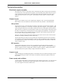
About this manual
This manual explains how to use the Communications Service Monitor 2948B.
It applies to instruments fitted with main software version 5.xx or later and
cellular software version 5.xx.
Intended audience
People who need to test mobile radio systems and associated equipment.
People who need to test airborne avionics receivers.
Structure
Chapter 1
General information and performance specification.
Chapter 2
Gives installation instructions, including connection of peripheral equipment.
Chapter 3
Operating instructions. Setting up and use.
Chapter 4
Brief technical description.
Chapter 5
Acceptance testing procedure for the Service Monitor.
Appendix A
Use of the Directional Power Heads, 54421/002 and 54421/003.
Appendix B
Operating instructions for Avionics system testing.
Document conventions
The following conventions apply throughout this manual:[Tx TEST]
Hard key titles are shown verbatim, using normal lettering in
square brackets.
[Tx freq]
Soft key titles are shown verbatim using italic lettering in square
brackets.
RF IN/OUT
Titles on the instrument panels are shown verbatim using capital
letters.
Text displayed on screen. See below†
†
References to text displayed on the screen of the Service Monitor are given verbatim, using
a font that resembles the displayed text. e.g. GEN FREQ: , Ref Level: , Ref.Level:
contd./...
ii
About this manual (continued)
Associated publications
Other manuals that cover specific aspects of this service monitor are:• Programming manual (46882/683) provides programming information for remote
control of the Service Monitor using MI-BASIC and GPIB.
• Maintenance Manual (46882/694) provides servicing information for the
Communications Service Monitor 2948B.
Operating manual supplements provide operating details for specific system test software.
• AMPS Supplement
(46882/313)
• EDACS Radio Supplement
(46882/301)
• EDACS Repeater Supplement (46882/300)
• MPT1327 Supplement
(46882/317)
• NMT Supplement
(46882/316)
• PMR Supplement
(46882/315)
• TACS Supplement
(46882/314)
iii
Contents
PRECAUTIONS.......................................................................................................................... v
Chapter 1
GENERAL INFORMATION ................................................................................................. 1-1
Performance data....................................................................................................... 1-7
Chapter 2
INSTALLATION ..................................................................................................................... 2-1
Chapter 3
LOCAL OPERATION............................................................................................................. 3-1
Using the test modes................................................................................................. 3-16
Chapter 4
TECHNICAL DESCRIPTION ............................................................................................... 4-1
Chapter 5
ACCEPTANCE TESTING ..................................................................................................... 5-1
Acceptance Test Results Tables .............................................................................. 5-31
Appendix A DIRECTIONAL POWER HEADS........................................................................................ A-1
Appendix B AVIONICS SYSTEM.............................................................................................................. B-1
Avionics system overview ......................................................................................... B-2
Avionics system operation ........................................................................................ B-7
INDEX ............................................................................................................................... Index-1
iv
PRECAUTIONS
Precautions
These terms have specific meanings in this manual:
WARNING
information to prevent personal injury.
information to prevent damage to the equipment.
important general information.
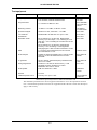
Hazard symbols
The meaning of hazard symbols appearing on the equipment and in the documentation is as
follows:
Symbol
Description
Refer to the operating manual when this symbol is marked on
the instrument. Familiarize yourself with the nature of the
hazard and the actions that may have to be taken.
Dangerous voltage
Toxic hazard
Hot surface
General conditions of use
This product is designed and tested to comply with the requirements of IEC/EN61010-1 ‘Safety
requirements for electrical equipment for measurement, control and laboratory use’, for Class I
portable equipment and is for use in a pollution degree 2 environment. The equipment is designed
to operate from an installation category I or II supply.
Equipment should be protected from the ingress of liquids and precipitation such as rain, snow,
etc. When moving the instrument from a cold to a hot environment, it is important to allow the
temperature of the instrument to stabilise before it is connected to the supply to avoid
condensation forming. The instrument must only be operated within the environmental conditions
specified in Chapter 1 ‘Performance Data’ in the Operating/Instruction manual.
This product is not approved for use in hazardous atmospheres or medical applications. If the
equipment is to be used in a safety-related application, e.g. avionics or military applications, the
suitability of the product must be assessed and approved for use by a competent person.
WARNING
Electrical hazards (AC supply voltage)
This equipment conforms with IEC Safety Class I, meaning that it is provided with a protective
grounding lead. To maintain this protection the supply lead must always be connected to the
source of supply via a socket with a grounded contact.
Be aware that the supply filter contains capacitors that may remain charged after the equipment is
disconnected from the supply. Although the stored energy is within the approved safety
requirements, a slight shock may be felt if the plug pins are touched immediately after removal.
Do not remove instrument covers as this may result in personal injury. There are no userserviceable parts inside.
Refer all servicing to qualified personnel. See list of Service Centers at rear of manual.
v
PRECAUTIONS
Fuses
Note that the internal supply fuse is in series with the live conductor of the supply lead. If
connection is made to an unpolarized supply socket, it is possible for the fuse to become
transposed to the neutral conductor, in which case, parts of the equipment could remain at supply
potential even after the fuse has ruptured.
WARNING
Fire hazard
Make sure that only fuses of the correct rating and type are used for replacement.
If an integrally fused plug is used on the supply lead, ensure that the fuse rating is commensurate
with the current requirements of this equipment. See under 'Performance Data' in Chapter 1 for
power requirements.
WARNING
Toxic hazards
Some of the components used in this equipment may include resins and other materials which give
off toxic fumes if incinerated. Take appropriate precautions, therefore, in the disposal of these
items.
WARNING
Lithium
A Lithium battery (or a Lithium battery contained within an IC) is used in this equipment:
As Lithium is a toxic substance, the battery should in no circumstances be crushed, incinerated or
disposed of in normal waste.
Do not attempt to recharge this type of battery. Do not short circuit or force discharge since this
might cause the battery to vent, overheat or explode.
WARNING
Beryllium copper
Some mechanical components within this instrument are manufactured from beryllium copper.
This is an alloy with a beryllium content of approximately 5%. It represents no risk in normal use.
The material should not be machined, welded or subjected to any process where heat is involved.
It must be disposed of as “special waste”.
It must NOT be disposed of by incineration.
WARNING
Hot Surfaces
Take care when touching the RF Input Type N connector after the application of high levels of
continuous power. If 50 W is exceeded for a prolonged period, the temperature of the connector
can become excessive.
WARNING
RF hazard
When measuring high VSWR ratios, hazardous voltages may be present on the line due to
standing waves. Under these conditions, it is dangerous to operate the equipment with the covers
removed.
vi
PRECAUTIONS
WARNING
Tilt facility
When the equipment is in the tilt position, it is advisable, for stability reasons, not to stack other
equipment on top of it.
Suitability for use
This equipment has been designed and manufactured by Aeroflex to generate, receive and analyze
RF/audio signals
If the equipment is not used in a manner specified by Aeroflex, the protection provided by the
equipment may be impaired.
Aeroflex has no control over the use of this equipment and cannot be held responsible for events
arising from its use other than for its intended purpose.
vii
PRECAUTIONS
Precautions
Les termes suivants ont, dans ce manuel, des significations particulières:
WARNING
contient des informations pour éviter toute blessure au personnel.
contient des informations pour éviter les dommages aux équipements.
contient d'importantes informations d'ordre général.
Symboles signalant un risque
La signification des symboles de danger apparaissant sur l'équipement et dans la documentation
est la suivante:
Symbole
Nature du risque
Reportez-vous au manuel d'utilisation quand ce symbole
apparaît sur l'instrument. Familiarisez-vous avec la nature du
danger et la conduite à tenir.
Tension dangereuse
Danger produits toxiques
Surfaces chaudes
Conditions générales d'utilisation
Ce produit a été conçu et testé pour être conforme aux exigences des normes CEI/EN61010-1
« exigences de sécurité des équipements électriques pour la mesure, le contrôle et l'usage en
laboratoire », pour des équipements Classe I portables et pour une utilisation dans un
environnement de pollution de niveau 2. Cet équipement est conçu pour fonctionner à partir d'une
alimentation de catégorie I ou II.
Cet équipement doit être protégé de l'introduction de liquides ainsi que des précipitations d'eau, de
neige, etc... Lorsqu'on transporte cet instrument d'un environnement chaud vers un environnement
froid, il est important de laisser l'instrument se stabiliser en température avant de le connecter à
une alimentation afin d'éviter toute formation de condensation. L'instrument doit être utilisé
uniquement dans les conditions d'environnement spécifiées dans le chapitre 1 « Performances » du
manuel d'utilisation.
Ce produit n’est pas garanti pour fonctionner dans des atmosphères dangereuses ou pour un usage
médical. Si l'équipement doit être utilisé pour des applications en relation avec la sécurité, par
exemple des applications militaires ou aéronautiques, la compatibilité du produit doit être établie
et approuvée par une personne compétente.
viii
PRECAUTIONS
WARNING
Sécurité électrique (tension d’alimentation alternative)
Cet appareil est protégé conformément à la norme CEI de sécurité Classe 1, c’est-à-dire que sa
prise secteur comporte un fil de protection à la terre. Pour maintenir cette protection, le câble
d’alimentation doit toujours être branché à la source d’alimentation par l’intermédiaire d’une prise
comportant une borne de terre.
Notez que les filtres d’alimentation contiennent des condensateurs qui peuvent encore être chargés
lorsque l’appareil est débranché. Bien que l’énergie contenue soit conforme aux exigences de
sécurité, il est possible de ressentir un léger choc si l’on touche les bornes sitôt après
débranchement.
Ne démontez pas le capot de l'instrument, car ceci peut provoquer des blessures. Il n'y a pas de
pièces remplaçables par l'utilisateur à l'intérieur.
Faites effectuer toute réparation par du personnel qualifié. Contacter un des Centres de
Maintenance Internationaux dans la liste jointe à la fin du manuel.
Fusibles
Notez que le fusible d'alimentation interne est en série avec la phase (fil brun) du cable
d'alimentation. Si la prise d'alimentation est non polarisée, il est possible de connecter le fusible
au neutre. Dans ce cas, certaines parties de l'appareil peuvent rester à un certain potentiel même
après coupure du fusible.
WARNING
Risque lié au feu
Lors du remplacement des fusibles vérifiez l'exactitude de leur type et de leur valeur.
Si le câble d'alimentation comporte une prise avec fusible intégré, assurez vous que sa valeur est
compatible avec les besoins en courant de l'appareil. Pour la consommation, reportez-vous au
Chapitre 1 "Spécifications".
WARNING
Danger produits toxiques
Certains composants utilisés dans cet appareil peuvent contenir des résines et d'autres matières qui
dégagent des fumées toxiques lors de leur incinération. Les précautions d'usages doivent donc être
prises lorsqu'on se débarrasse de ce type de composant.
WARNING
Lithium
Une pile au Lithium ou un CI contenant une pile au Lithium est utilisé dans cet équipement.
Le Lithium est une substance toxique; en conséquence on ne doit l'écraser, l'incinérer ou la jeter
dans la "poubelle".
Ne pas essayer de la recharger, ne pas la court-circuiter, une forte décharge rapide risque de
provoquer une surchauffe voire l'explosion de celle-ci.
WARNING
Bronze au béryllium
Dans cet équipement,certaines pièces mécaniques sont à base de bronze au béryllium. Il s'agit d'un
alliage dans lequel le pourcentage de béryllium ne dépasse pas 5%. Il ne présente aucun danger en
utilisation normale.
Toutefois, cet alliage ne doit pas être travaillé, soudé ou soumis à un processus qui implique
l'utilisation d'une source de chaleur.
En cas de destruction, il sera entreposé dans un container spécial. IL ne devra pas être détruit par
incinération.
ix
PRECAUTIONS
WARNING
Surfaces chaudes
Faire attention ,lors de la manipulation d'un connecteur "N", après l'injection de haute puissance en
continu sur l'entrée RF de ce connecteur: Si une puissance supérieure à 50 W est envoyée pendant
une longue durée, la température du connecteur peut être très élevée.
WARNING
Danger RF
Lors de la mesure de T.O.S. de valeur importante, des tensions dangereuses dues aux ondes
stationnaires peuvent apparaître sur l’alimentation. Dans ces conditions il est dangereux de faire
fonctionner l’appareil sans ses capots de protection.
WARNING
Position inclinée
Lorsque l’appareil est dans une position inclinée, il est recommandé, pour des raisons de stabilité,
de ne pas y empiler d’autres appareils.
Utilisation
Cet équipement a été conçu et fabriqué par Aeroflex pour générer, recevoir et analyser des signaux
RF et audios
La protection de l'équipement peut être altérée s'il n'est pas utilisé dans les conditions spécifiées
par Aeroflex.
Aeroflex n'a aucun contrôle sur l'usage de l'instrument, et ne pourra être tenu pour responsable en
cas d'événement survenant suite à une utilisation différente de celle prévue.
x
PRECAUTIONS
Vorsichtsmassnahmen
Diese Hinweise haben eine bestimmte Bedeutung in diesem Handbuch:
WARNING
dienen zur Vermeidung von Verletzungsrisiken.
dienen dem Schutz der Geräte.
enthalten wichtige Informationen.
Gefahrensymbole
Die Bedeutung der Gefahrensymbole auf den Geräten und in der Dokumentation ist wie folgt:
Symbol
Gefahrenart
Beziehen Sie sich auf die Bedienungsanleitung wenn das
Messgerät mit diesem Symbol markiert ist. Machen Sie sich
mit der Art der Gefahr und den Aktionen die getroffen
werden müssen bekannt.
Gefährliche Spannung
Warnung vor giftigen Substanzen
Heiße Oberfläche
Allgemeine Hinweise zur Verwendung
Dieses Produkt wurde entsprechend den Anforderungen von IEC/EN61010-1
"Sicherheitsanforderungen für elektrische Ausrüstung für Meßaufgaben, Steuerung und
Laborbedarf", Klasse I transportabel zur Verwendung in einer Grad 2 verunreinigten Umgebung,
entwickelt und getestet. Dieses Gerät ist für Netzversorgung Klasse I oder II zugelassen.
Das Meßgerät sollte vor dem Eindringen von Flüssigkeiten sowie vor Regen, Schnee etc.
geschützt werden. Bei Standortänderung von kalter in wärmere Umgebung sollte das Meßgerät
wegen der Kondensation erst nach Anpassung an die wärmere Umgebung mit dem Netz
verbunden werden. Das Meßgerät darf nur in Umgebungsbedingungen wie in Kapitel 1
"Leistungsdaten (Performance data)" der Bedienungsanleitung beschrieben, betrieben werden.
Dieses Produkt ist nicht für den Einsatz in gefährlicher Umgebung (z.B. Ex-Bereich) und für
medizinische Anwendungen geprüft. Sollte das Gerät für den Einsatz in sicherheitsrelevanten
Anwendungen wie z.B. im Flugverkehr oder bei militaerischen Anwendungen vorgesehen sein, so
ist dieser von einer für diesen Bereich zuständigen Person zu beurteilen und genehmigen.
WARNING
Elektrische Schläge (Wechselspannungsversorgung)
Das Gerät entspricht IEC Sicherheitsklasse 1 mit einem Schutzleiter nach Erde. Das Netzkabel
muß stets an eine Steckdose mit Erdkontakt angeschlossen werden.
Filterkondensatoren in der internen Spannungsversorgung können auch nach Unterbrechung der
Spannungszuführung noch geladen sein. Obwohl die darin gespeicherte Energie innerhalb der
Sicherheitsmargen liegt, kann ein leichter Spannungsschlag bei Berührung kurz nach der
Unterbrechung erfolgen.
Öffnen Sie niemals das Gehäuse der Geräte das dies zu ernsthaften Verletzungen führen kann. Es
gibt keine vom Anwender austauschbare Teile in diesem Gerät.
Lassen Sie alle Reparaturen durch qualifiziertes Personal durchführen. Eine Liste der
Servicestellen finden Sie auf der Rückseite des Handbuches.
xi
PRECAUTIONS
Sicherungen
Die interne Sicherung in der Spannungszuführung ist in Reihe mit der spannungsführenden
Zuleitung (braun) geschaltet. Bei Verbindung mit einer nicht gepolten Steckdose kann die
Sicherung in der Masseleitung liegen, so daß auch bei geschmolzener Sicherung Geräteteile immer
noch auf Spannungspotential sind.
WARNING
Feuergefahr
Es dürfen nur Ersatzsicherungen vom gleichen Typ mit den korrekten Spezifikationen
entsprechend der Stromaufnahme des Gerätes verwendet werden. Siehe hierzu die Leistungsdaten
(Performance Data) in Kapitel 1.
WARNING
Warnung vor giftigen Substanzen
In einigen Bauelementen dieses Geräts können Epoxyharze oder andere Materialien enthalten sein,
die im Brandfall giftige Gase erzeugen. Bei der Entsorgung müssen deshalb entsprechende
Vorsichtsmaßnahmen getroffen werden.
WARNING
Lithium
Eine Lithium Batterie oder eine Lithium Batterie innerhalb eines IC ist in diesem Gerät eingebaut.
Da Lithium ein giftiges Material ist, sollte es als Sondermüll entsorgt werden.
Diese Batterie darf auf keinen Fall geladen werden. Nicht kurzschließen, da sie dabei überhitzt
werden und explodieren kann.
WARNING
Beryllium Kupfer
In diesem Gerät sind einige mechanische Komponenten aus Berylium Kupfer gefertigt. Dies ist
eine Verbindung welche aus einem Berylliumanteil von ca. 5 % besteht. Bei normaler
Verwendung besteht kein Gesundheitsrisiko.
Das Metall darf nicht bearbeitet, geschweißt oder sonstiger Wärmebehandlung ausgesetzt werden.
Es muß als Sondermüll entsorgt werden.
Es darf nicht durch Verbrennung entsorgt werden.
WARNING
Heiße Oberfläche
Vorsicht bei Berührung der HF Eingangsbuchse Typ N nach Einspeisen hoher Dauerleistung.
Falls über längere Zeit 50 Watt überschritten wird, kann die Temperatur der Buchse über Normal
steigen.
WARNING
Hochfrequenz
Bei Messung von hohen Stehwellenverhältnissen können sich auf der Leitung gefährliche
Spannungen aufbauen. In solchen Fällen darf das Gerät nicht bei geöffnetem Gehäuse betrieben
werden.
WARNING
Schrägstellung
Bei Schrägstellung des Geräts sollten aus Stabilitätsgründen keine anderen Geräte darauf gestellt
werden.
xii
PRECAUTIONS
Eignung für Gebrauch
Dieses Gerät wurde von Aeroflex entwickelt und hergestellt um HF/Audio Signale zu erzeugen, zu
empfangen und zu analysieren
Sollte das Gerät nicht auf die von Aeroflex vorgesehene Art und Weise verwendet werden, kann
die Schutzfunktion des Gerätes beeinträchtigt werden.
Aeroflex hat keinen Einfluß auf die Art der Verwendung und übernimmt keinerlei Verantwortung
bei unsachgemässer Handhabung.
xiii
PRECAUTIONS
Precauzioni
Questi termini vengono utilizzati in questo manuale con significati specifici:
WARNING
riportano informazioni atte ad evitare possibili pericoli alla persona.
riportano informazioni per evitare possibili pericoli all'apparec-chiatura.
riportano importanti informazioni di carattere generale.
Simboli di pericolo
Il significato del simbolo di pericolo riportato sugli strumenti e nella documentazione è il
seguente:
Simbolo
Tipo di pericolo
Fare riferimento al manuale operativo quando questo
simbolo è riportato sullo strumento. Rendervi conto della
natura del pericolo e delle precauzioni che dovrete prendere.
Tensione pericolosa
Pericolo sostanze tossiche
Superfici ad alta temperatura
Condizioni generali d'uso.
Questo prodotto è stato progettato e collaudato per rispondere ai requisiti della direttiva
IEC/EN61010-1 'Safety requirements for electrical equipment for measurement, control and
laboratory use' per apparati di classe I portatili e per l'uso in un ambiente inquinato di grado 2.
L'apparato è stato progettato per essere alimentato da un alimentatore di categoria I o II.
Lo strumento deve essere protetto dal possibile ingresso di liquidi quali, ad es., acqua, pioggia,
neve, ecc. Qualora lo strumento venga portato da un ambiente freddo ad uno caldo, è importante
lasciare che la temperatura all'interno dello strumento si stabilizzi prima di alimentarlo per evitare
formazione di condense. Lo strumento deve essere utilizzato esclusivamente nelle condizioni
ambientali descritte nel capitolo 1 'Performance Data' del manuale operativo.
Questo prodotto non è stato approvato per essere usato in ambienti pericolosi o applicazioni
medicali. Se lo strumento deve essere usato per applicazioni particolari collegate alla sicurezza
(per esempio applicazioni militari o avioniche),occorre che una persona o un istituto competente
ne certifichi l'uso.
WARNING
Pericoli da elettricità (alimentazione c.a.)
Quest ’apparato è provvisto del collegamento di protezione di terra e rispetta le norme di sicurezza
IEC, classe 1. Per mantenere questa protezione è necessario che il cavo, la spina e la presa
d’alimentazione siano tutti provvisti di terra.
Il circuito d’alimentazione contiene dei filtri i cui condensatori possono restare carichi anche dopo
aver rimosso l’alimentazione. Sebbene l’energia immagazzinata è entro i limiti di sicurezza,
purtuttavia una leggera scossa può essere avvertita toccando i capi della spina subito dopo averla
rimossa.
Non rimuovete mai le coperture perché così potreste provocare danni a voi stessi. Non vi sono
all’interno parti di interesse all’utilizzatore.
Tutte gli interventi sono di competenza del personale qualificato. Vedi elenco internazionale dei
Centri di Assistenza in fondo al manuale.
xiv
PRECAUTIONS
Fusibili
Notare che un fusibile è posto sul filo caldo (marrone) del cavo di alimentazione. Se
l'alimentazione avviene tramite una presa non polarizzata, è possibile che il fusibile vada a
protezione del neutro per cui anche in caso di una sua rottura, l'apparato potrebbe restare sotto
tensione.
WARNING
Pericolo d'incendio
Assicurarsi che, in caso di sostituzione, vengano utilizzati solo fusibili della portata e del tipo
prescritti.
Se viene usata una spina con fusibili, assicurarsi che questi siano di portata adeguata coi requisiti
di alimentazione richiesti dallo strumento. Tali requisiti sono riportati nel cap. 1 "Performance
data".
WARNING
Pericolo sostanze tossiche
Alcuni dei componenti usati in questo strumento possono contenere resine o altri materiali che, se
bruciati, possono emettere fumi tossici. Prendere quindi le opportune precauzioni nell'uso di tali
parti.
WARNING
Litio
Quest'apparato incorpora una batteria al litio o un circuito integrato contenente una batteria al litio.
Poiché il litio è una sostanza tossica, la batteria non deve essere mai né rotta, né incenerita, né
gettata tra i normali rifiuti.
Questo tipo di batteria non può essere sottoposto né a ricarica né a corto-circuito o scarica forzata.
Queste azioni possono provocare surriscaldamento, fuoriuscita di gas o esplosione della batteria.
WARNING
Rame berillio
Alcuni componenti meccanici in questo strumento sono realizzati in rame berillio. Si tratta di una
lega con contenuto di berillio di circa il 5%, che non presenta alcun rischio in usi normali.
Questo materiale non deve essere lavorato, saldato o subire qualsiasi processo che coinvolge alte
temperature.
Deve essere eliminato come "rifiuto speciale". Non deve essere eliminato tramite "inceneritore".
WARNING
Superfici ad alta temperatura
Fare attenzione nel toccare il connettore d'ingresso di tipo N dopo aver applicato una potenza
elevata e continua. Una potenza superiore a 50 W per tempi prolungati può portare il connettore
ad una temperatura molto elevata.
WARNING
Rischio a RF
Durante la misura di ROS di valori elevati, la presenza di onde stazionarie può causare tensioni
pericolose. In queste condizioni è quindi rischioso usare lo strumento coi coperchi rimossi.
WARNING
Posizionamento inclinato
Quando lo strumento è in posizione inclinata è raccomandato, per motivi di stabilità, non
sovrapporre altri strumenti.
xv
PRECAUTIONS
Caratteristiche d’uso
Questo strumento è stato progettato e prodotto da Aeroflex generare, ricevere ed analizzare segnali
RF/audio
Se lo strumento non è utilizzato nel modo specificato da Aeroflex, le protezioni previste sullo
strumento potrebbero risultare inefficaci.
Aeroflex non può avere il controllo sull’uso di questo strumento e non può essere ritenuta
responsabile per eventi risultanti da un uso diverso dallo scopo prefisso.
xvi
PRECAUTIONS
Precauciones
Estos términos tienen significados específicos en este manual:
WARNING
contienen información referente a prevención de daños personales.
contienen información referente a prevención de daños en equipos.
contienen información general importante.
Símbolos de peligro
El significado de los símbolos de peligro en el equipo y en la documentación es el siguiente:
Símbolo
Naturaleza del peligro
Vea el manual de funcionamiento cuando este símbolo
aparezca en el instrumento. Familiarícese con la naturaleza
del riesgo y con las acciones que deban de tomarse.
Voltaje peligroso
Aviso de toxicidad
Superficies a altas temperaturas
Condiciones generales de uso
Este producto ha sido diseñado y probado para cumplir los requerimientos de la normativa
IEC/EN61010-1 "Requerimientos de la normativa para equipos eléctricos de medida, control y uso
en laboratorio", para equipos clase I portátiles y para uso en un ambiente con un grado de
contaminación 2. El equipo ha sido diseñado para funcionar sobre una instalación de alimentación
de categorías I o II.
Debe protegerse el equipo de la entrada de líquidos y precipitaciones como nieve, lluvia, etc.
Cuando se traslada el equipo de entorno frío a un entorno caliente, es importante aguardar la
estabilización el equipo para evitar la condensación. Sólo debe utilizarse el aparato en las
condiciones ambientales especificadas en el capítulo 1 "Especificaciones" o "Performance Data"
del Manual de Instrucciones/Manual de Operación/Funcionamiento.
Este producto no ha sido aprobado para su utilización en entornos peligrosos o en aplicaciones
médicas. Si se va a utilizar el equipo en una aplicación con implicaciones en cuanto a seguridad,
como por ejemplo aplicaciones de aviónica o militares, es preciso que un experto competente en
materia de seguridad apruebe su uso.
WARNING
Nivel peligroso de electricidad (tensión de red)
Este equipo cumple las normas IEC Seguridad Clase 1, lo que significa que va provisto de un
cable de protección de masa. Para mantener esta protección, el cable de alimentación de red debe
de conectarse siempre a una clavija con terminal de masa.
Tenga en cuenta que el filtro de red contiene condensadores que pueden almacenar carga una vez
desconectado el equipo. Aunque la energía almacenada está dentro de los requisitos de seguridad,
pudiera sentirse una ligera descarga al tocar la clavija de alimentación inmediatamente después de
su desconexión de red.
No retire las cubiertas del chasis del instrumento, ya que pudiera resultar dañado personalmente.
No existen partes que puedan ser reparadas en su interior.
Deje todas las tareas relativas a reparación a un servicio técnico cualificado. Vea la lista de
Centros de Servicios Internacionales en la parte trasera del manual.
xvii
PRECAUTIONS
Fusibles
Se hace notar que el fusible de alimentación interno está enserie con el activo (marrón) del cable
de alimentación a red. Si la clavija de alimentación de red no tiene polaridad, el fusible puede
pasar a estar en serie con el neutro, en cuyo caso existen partes del equipo que permanecerían a
tensión de red incluso después de que el fusible haya fundido.
WARNING
Peligro de incendio
Asegúrese de utilizar sólo fusibles del tipo y valores especificados como repuesto.
Si se utiliza una clavija con fusible incorporado, asegúrese de que los valores del fusible
corresponden a los requeridos por el equipo. Ver sección de especificaciones del capítulo 1 para
comprobar los requisitos de alimentación.
WARNING
Aviso de toxicidad
Alguno de los componentes utilizados en este equipo pudieran incluir resinas u otro tipo de
materiales que al arder produjeran sustancias tóxicas, Por tanto, tome las debidas precauciones en
la manipulación de esas piezas.
WARNING
Litio
En este equipo se utiliza una batería de litio (o contenida dentro de un CI).
Dada que el litio es una substancia tóxica las baterías de este material no deben ser aplastadas,
quemadas o arrojadas junto a basuras ordinarias.
No trate de recargar este tipo de baterías. No las cortocircuite o fuerce su descarga ya que puede
dar lugar a que la esta emita gases, se recaliente o explote.
WARNING
Berilio-cobre
Algunos componentes mecánicos contenidos en este instrumento incorporan berilio-cobre en su
proceso de fabricación. Se trata de una aleación con un contenido aproximado de berilio del 5%,
lo que no representa ningún riesgo durante su uso normal.
El material no debe ser manipulado, soldado, ni sometido a ningún proceso que implique la
aplicación de calor.
Para su eliminación debe tratarse como un "residuo especial". El material NO DEBE eliminarse
mediante incineración.
WARNING
Superficies a altas temperaturas
Tenga cuidado al tocar el conector de entrada RF tipo N tras la aplicación continuada de altos
niveles de potencia. La temperatura del conector puede llegar a ser excesiva si se sobrepasan
50 W durante un periodo prolongado de tiempo.
WARNING
Riesgo de RF
Cuando se miden valores elevados de ROE, pueden existir tensiones elevadas debido a ondas
estacionarias. Bajo estas condiciones resulta peligroso operar con el equipo sin las tapas puestas.
WARNING
Tener en cuenta con el equipo inclinado
Si utiliza el equipo en posición inclinada, se recomienda, por razones de estabilidad, no apilar
otros equipos encima de él.
xviii
PRECAUTIONS
Idoneidad de uso
Este equipo ha sido diseñado y fabricado por Aeroflex para generar, recibir y analizar señales de
RF/audio
Si el equipo fuese utilizado de forma diferente a la especificada por Aeroflex, la protección
ofrecida por el equipo pudiera quedar reducida.
Aeroflex no tiene control sobre el uso de este equipo y no puede, por tanto, exigirsele
responsabilidades derivadas de una utilización distinta de aquellas para las que ha sido diseñado.
xix
Chapter 1
GENERAL INFORMATION
Contents
Purpose and features ...................................................................................................................... 1-2
Transmitter testing .................................................................................................................. 1-3
Receiver testing....................................................................................................................... 1-4
Duplex testing......................................................................................................................... 1-4
Systems testing ....................................................................................................................... 1-5
Spectrum analyzer................................................................................................................... 1-6
AF testing................................................................................................................................ 1-6
Performance data......................................................................................................................... 1-7
Receiver measurements .......................................................................................................... 1-7
Audio analyzer........................................................................................................................ 1-9
Transmitter measurements .................................................................................................... 1-11
RF spectrum analyzer ........................................................................................................... 1-13
Audio generators................................................................................................................... 1-14
Cellular and trunking ............................................................................................................ 1-15
Frequency standard ............................................................................................................... 1-15
General.................................................................................................................................. 1-16
General features .................................................................................................................... 1-16
Options and accessories ........................................................................................................ 1-17
List of figures
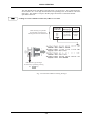
Fig. 1-1
Fig. 1-2
Fig. 1-3
Fig. 1-4
Fig. 1-5
Fig. 1-6
Transmitter test set-up ..................................................................................................... 1-3
Receiver test setup........................................................................................................... 1-4
One port duplex test setup............................................................................................... 1-4
Two port duplex test setup .............................................................................................. 1-5
Cellular radio-telephone test setup .................................................................................. 1-5
AF test setup.................................................................................................................... 1-6
1-1
GENERAL INFORMATION
Purpose and features
2948B is a portable Communications Service Monitor for carrying out production, routine and
maintenance testing on radio transmitters, receivers and two way radio communication equipment.
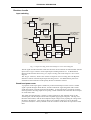
The SYSTEM mode provides test facilities for ILS, VOR and SELCAL receivers. The Service
Monitor contains modules to provide facilities equivalent to the following instruments:RF generator, two audio generators, specialized tones generator, RF power meter, modulation
meter, RF counter, AF counter, AF voltmeter, distortion meter, large screen digital oscilloscope,
spectrum analyzer and monitoring receiver.
Distortion measuring filters, AF post demodulation filters and IF passband filters, are built in for
inclusion in relevant measurement paths.
The signal obtained from the demodulators, when in Tx test mode, is fed to an AF amplifier and
can be monitored on the built-in loudspeaker, on headphones connected to the accessory socket, or
taken from the DEMOD OUT connector to other equipment.
The monitor has a wide range of test capabilities including base station, mobile and transponder
commissioning and servicing, radio telephone system and radio pager testing, as well as
production testing to all of the above.
The selection of a test mode configures the modules into set-ups ready for connection to the
equipment to be tested and produces the appropriate set-up screen on the display. The set-up
screen shows the settings of the active modules, records changes to settings as they are made and
gives readouts of test results both digitally and on barcharts.
The modules of the monitor can each be used to perform as individual test instruments.
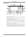
A hard copy of most screens can be made to a suitable printer using the screen capture feature.
This is one of the functions accessed after pressing the [DISPLAY HOLD] key on the front panel.
See Front panel layout, DISPLAY HOLD key, in Chapter 3.
A memory facility allows settings and test results to be stored within the Service Monitor. With
the memory card option fitted, these can be stored on memory cards. This also allows settings to
be exchanged between Service Monitors.
The memory card option also includes a real time clock which provides date/time stamping to
stored results and to screen-capture printouts.
The RS232 control facility permits operation of the Service Monitor by remote or automatic
control as an alternative or supplement to the conventional front panel local control.
The programming manual 46882/318, supplied with the Service Monitor provides comprehensive
information relating to operation by remote control. It also contains the command list, with
structure details and examples.
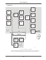
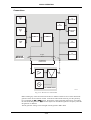
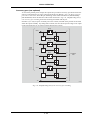
The test modes are outlined in the following descriptions, with interconnection diagrams showing
the principles of the test procedures.
1-2
GENERAL INFORMATION
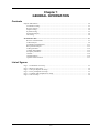
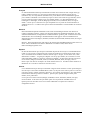
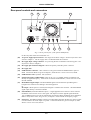
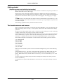
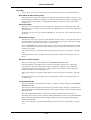
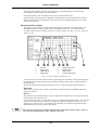
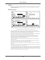
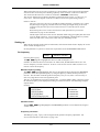
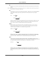
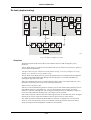
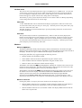
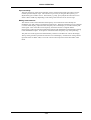
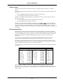
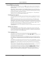
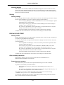
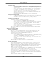
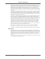
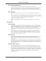
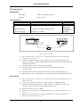
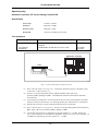
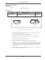
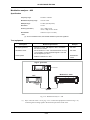
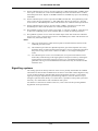
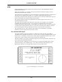
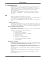
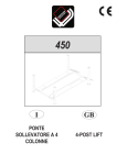
Transmitter testing
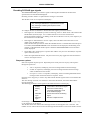
Service Monitor
MODULATED RF SIGNAL
Tx
Under
Test
AF GENERATOR
OUTPUT
AF (MODULATION)
INPUT
C3240
Fig. 1-1 Transmitter test set-up
The transmitter test procedure uses:The AF generators, to provide a source of modulation for the transmitter under test.
The RF power meter, to measure the mean output power level of the transmitter.
The RF counter, to obtain the mean RF frequency of the transmitter output.
The modulation meter, to measure the modulation depth or the deviation level and to
provide a demodulated output signal. Single sideband transmissions can be demodulated
when the SSB option is implemented.
The AF counter, to measure the frequency of the demodulated signal.
The distortion meter, to obtain the signal to noise level, the modulation distortion
percentage or the modulation SINAD level of the transmitter.
The oscilloscope, to view the demodulated signal and to measure the modulation levels.
The tones generator, to modulate transmitters of systems using tone calling.
The tones decoder, to demodulate tones generated by the transmitter.
The AF amplifier and loudspeaker, to monitor the demodulated signal.
Cellular radio-telephones can be tested using the SYSTEMS mode. (See 'System testing').
The spectrum analyzer facility, which is a separate operating mode (SPEC ANA), can be used to
study the sidebands and any harmonics produced by the transmitter, either by direct connection or
by off-air monitoring.
1-3
GENERAL INFORMATION
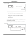
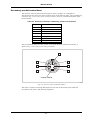
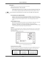
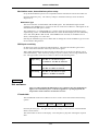
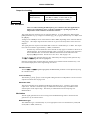
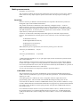
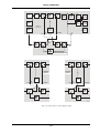
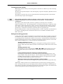
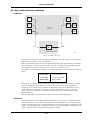
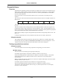
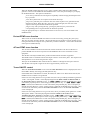
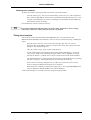
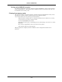
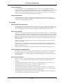
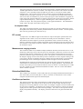
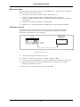
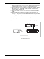
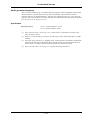
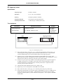
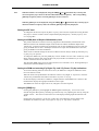
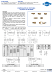
Receiver testing
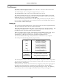
Service Monitor
MODULATED RF TEST SIGNAL
DEMODULATED AF SIGNAL
Rx
Under
Test
C3241
Fig. 1-2 Receiver test setup
The receiver test procedure uses:The RF generator and the AF generators, to produce a transmission with defined
parameters.
The AF voltmeter, to measure the level of the demodulated signal from the receiver.
The distortion meter, to obtain signal-to-noise ratio, SINAD levels and distortion
percentage figures.
The tone generator and tone detector, to produce and decode specialized calling tones to test
tone recognition circuits.
The oscilloscope, to view and measure the demodulated signal or other waveforms.
The RF signal from the Service Monitor is coupled to the receiver and the demodulated signal
from the receiver taken to the AF input of the Service Monitor. By measuring the levels of the AF
signal from the receiver, the sensitivity of the receiver can be checked. The distortion levels
introduced by the receiver can be measured.
During all of the above procedures, the RF levels, the distortion levels and modulation levels can
be displayed on bar charts as well as being provided as a digital read-out. The AF waveforms can
also be studied using the digital oscilloscope facility.
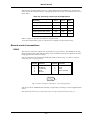
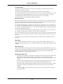
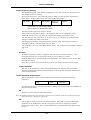
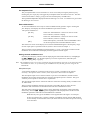
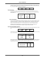
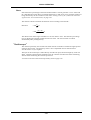
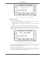
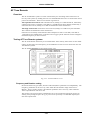
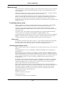
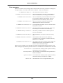
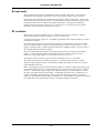
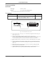
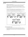
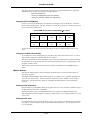
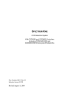
Duplex testing
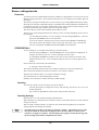
Service Monitor
MODULATED
RF TEST
SIGNAL
RF SIGNAL
FROM RADIO
UNDER TEST
DEMODULATED AF SIGNAL
Rx/Tx
Under
Test
AF GENERATOR OUTPUT
C5442
Fig. 1-3 One port duplex test setup
1-4
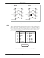
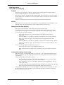
GENERAL INFORMATION
Service Monitor
MODULATED RF TEST SIGNAL
MODULATED RF SIGNAL
DEMODULATED AF SIGNAL
Rx/Tx
Under
Test
AF GENERATOR OUTPUT
C5385
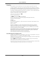
Fig. 1-4 Two port duplex test setup
Using the Duplex test facility, parameters for transmitter testing and receiver testing can be set up
and displayed on one screen. This gives the capability to study the performance of duplex
transceivers. Both one port and two port units can be tested.
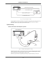
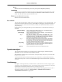
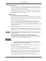
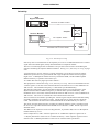
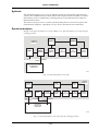
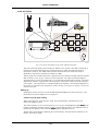
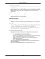
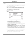
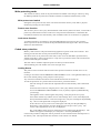
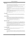
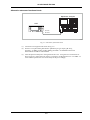
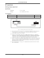
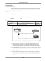
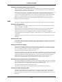
Systems testing
Cellular and trunked radio-telephone systems
Service Monitor
!
RF
!
AF OUT
AF IN
+
SERVICE
CONNECTION
DC
SUPPLY
C3253
Fig. 1-5 Cellular radio-telephone test setup
With the appropriate cellular or trunked mobile telephone option included, the monitor has built-in
software to generate and interrogate signals of the various cellular or trunked telephone systems.
This gives the facility for testing all aspects of these systems.
Inbuilt test programs and user programming facilities give speed and flexibility to these tests.
1-5
GENERAL INFORMATION
Operating instructions for each of the SYSTEM test options is given in separate supplements to
this manual. These supplements are supplied, as appropriate, with Service Monitors fitted with
SYSTEM testing options.
Avionics systems
The Avionics SYSTEM test facility is capable of carrying out functional testing and performance
evaluation of airborne radio navigation and communication equipment. Appendix B, Avionics
System, covers the operation of this facility.
Spectrum analyzer
The SPEC ANA mode allows ‘off air’ and directly coupled RF signals to be studied and
monitored.
Sideband spread, harmonic levels and RF interference can be examined.
The frequency range of the spectrum analyzer is from 100 kHz to 1.0 GHz with the start and stop
frequencies of the sweep infinitely variable from within this range.
The tracking generator permits frequency response tests to be made to frequency dependent
circuits and the frequency offset facility extends this capability into the area of frequency shifting
circuits, such as mixers.
The ‘Look and Listen’ function gives the ability to demodulate a signal displayed on the spectrum
analyzer and monitor the signal obtained on the built-in loudspeaker, on headphones or other data
output equipment.
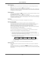
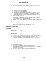
AF testing
Service Monitor
AUDIO
Amplifier
Under
Test
AUDIO
C3244
Fig. 1-6 AF test setup
The AF testing mode allows the dual AF generators and the tones generator to be used as a signal
source. The AF voltmeter, distortion meter, bar chart displays and the AF counter can all be used
to provide data relating to signals applied to the AF input connector. The digital oscilloscope is
also available for studying AF waveforms.
1-6
GENERAL INFORMATION
Performance data
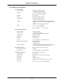
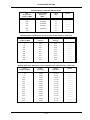
Receiver measurements
RF signal generator
Frequency
Range
400 kHz to 1.05 GHz
Resolution
10 Hz
Indication
10 digit display
Setting
Keyboard entry, delta increment / decrement function and rotary
control
Accuracy
As frequency standard
Output Level
Range
Rx Test:
N-Type socket: −141 dBm to −21 dBm
BNC socket: −115 dBm to +5 dBm (usable to +7 dBm)
Resolution
0.1 dB
Indication
4 digits plus sign (dBm, dBμV, μV, mV, PD/EMF).
Accuracy
± 2 dB for level above −127 dBm on N-Type socket up to 1 GHz
Attenuator Hold Facility
Allows user to define start point for seamless generator operation
across a range of up to 20 dB (guaranteed 10 dB minimum).
CW and FM modes only
Reverse Power Protection
N-Type: 50 W for 10 minutes, normal operation. 150 W for 1 minute
at 20°C.
Overload indicated by audible and visual warning.
BNC: 5 W Tripping indicated by audible and visual warning.
Output Impedance
Nominally 50 Ω
VSWR N-Type
Better than 1.2:1 up to 500 MHz
Better than 1.35:1 up to 1.05 GHz
VSWR BNC
Better than 2.2:1 up to 1.05 GHz
Spectral Purity
Residual FM
Less than 6 Hz RMS (0.3 to 3.4 kHz) <500 MHz
Less than 12 Hz RMS (0.3 to 3.4 kHz)
Harmonics
Better than −25 dBc
Spurious signals
Better than −50 dBc
SSB phase noise (20 kHz offset)
Better than −112 dBc / Hz <500 MHz
Better than −108 dBc / Hz up to 1 GHz
RF carrier leakage
Less than 0.5 μV PD generated in a 50 Ω load by a 2 turn loop 25 mm
from the case. Output level less than −40 dBm into a sealed 50 Ω
load.
1-7
GENERAL INFORMATION
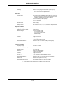
Amplitude Modulation – Internal
Frequency range
400 kHz to 1.05 GHz
AM depth range
0 to 99 %
Resolution
1%
Indication
2 digits
Setting
Keyboard entry, delta increment / decrement function
and rotary control
Accuracy
For carrier frequencies from 1.5 MHz to 400 MHz:
±5% at 50 % for mod freq of 1 kHz,
±7% ±1 digit, for mod freq of 1 kHz,
±15% ±1 digit, for mod freq of 50 Hz to 15 kHz
Distortion
Less than 2 % at 1 kHz for 30 %, CCITT weighted
Modulation Frequency Range
5 Hz to 33 kHz
Amplitude Modulation – External
Input impedance
Nominally 10 kΩ in parallel with 40 pF
Frequency Range
As internal AM
Modulation Frequency Range
As internal AM
Sensitivity
1.0 V RMS for 0 to 100% AM
Frequency Modulation – Internal
Frequency range
400 kHz to 1.05 GHz
Maximum deviation
75 kHz
Indication
3 digits
Setting
Keyboard entry, delta increment / decrement function and rotary
control
Accuracy †
±7% at 1 kHz modulating frequency
±10% at modulating frequencies from 50 Hz to 15 kHz
Distortion
Less than 1% at 1 kHz for deviation of 5 kHz, CCITT weighted
Resolution
25 Hz
Pre-emphasis
750 μs selectable
Mod Frequency Range
5 Hz – 33 kHz
Frequency Modulation – External
Input impedance
Nominally 10 kΩ in parallel with 40 pF
Frequency Range
As internal FM
Modulation Frequency Range
DC to 100 kHz
Pre-emphasis
750 μs selectable
Sensitivity
1 V RMS for 0 to 75 kHz deviation
Microphone Input
Input Level
2 mV to 200 mV (AGC levelled)
Input Impedance
Nominally 150 Ω
Press To Talk (PTT)
When using the optional microphone in Tx Test mode, the PTT will
switch the Service Monitor to Rx Test
† At low modulation levels the residual AM / FM may become significant
1-8
GENERAL INFORMATION
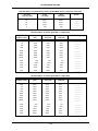
Audio analyzer
Audio Voltmeter
Input Impedance
Nominally 1 MΩ in parallel with 40 pF
Frequency Range
DC and 20 Hz to 50 kHz
AC only 20 Hz to 50 kHz
Polarized DC (below 1 Hz)
Maximum Input Voltage
30 V RMS, 50 V DC
Level Ranges
0-100 mV to 0-100 V RMS in a 1,3,10 sequence
Resolution
1 mV or 1% of reading
Indication
3 digits and barchart
Accuracy (AC)
±3% ±3 mV ± resolution up to 30 V RMS
Accuracy (DC)
±1% +50 mV up to 40 V
Audio Frequency Meter
Frequency Range
20 Hz to 50 kHz
Resolution
0.1 Hz, less than 10 kHz
1 Hz, at 10 kHz and above
Indication
5 digits
Accuracy
As frequency standard ± 1 digit ± resolution
Sensitivity
50 mV
Audio SINAD Meter
Frequency
1 kHz (additional frequencies available with Option 29)
Range
0 to 18 dB and 0 to 50 dB
Resolution
0.1 dB
Indication
3 digits and barcharts
Accuracy
± 1 dB
Sensitivity
50 mV (100 mV for 40 dB SINAD). Reading suppressed if audio
voltage is less than 5 mV.
Audio Distortion Meter
Frequency
1 kHz (additional frequencies available with Option 29)
Range
0 to 10 % and 0 to 30 %
Resolution
0.1 % distortion
Indication
3 digits and barcharts
Accuracy
± 1 dB of reading ± 0.5 % distortion
Sensitivity
50 mV (100 mV for 1 % distortion). Reading suppressed if audio
voltage is less than 5 mV.
Audio S/N Meter
Range
0 to 30 dB and 0 to 100 dB
Resolution
0.1 dB
Indication
3 digits and barchart
Accuracy
± 1 dB
Sensitivity
50 mV (100 mV for 40 dB S/N). Reading suppressed if audio
voltage is less than 5 mV.
1-9
GENERAL INFORMATION
Audio Oscilloscope
Operating Modes
Single or repetitive sweep
Frequency Range
DC to 50 kHz, 3 Hz to 50 kHz AC coupled
Voltage Range
10 mV to 20 V per division in a 1,2,5 sequence
Voltage Accuracy
± 5 % of full scale
FM Ranges
±75, 30, 15, 6, 3 and 1.5 kHz deviation full scale, ±10 % accuracy
AM Ranges
20, 10 and 5 % per division, ±10 % accuracy
Timebase
50 μs/div to 5 s/div in a 1,2,5 sequence
Graticule
10 Horizontal by 6 Vertical divisions
Special features
Built in antialiasing circuitry
Audio Barcharts
Barchart Displays
AF Voltage, SINAD, Distortion, S/N
Vertical Resolution
2 % of full scale
Ranging
Autoranging, range hold or manual selection 1, 2, 5, sequence
with hysteresis
Audio and Modulation Filters
Lowpass Filters
Four independently configurable Lowpass filters LP1, LP2, LP3,
LP4 that can be set to any frequency cut off point from 250 Hz
to 20,000 Hz (excluding the band 1001 to 2999 Hz).
A 50 kHz Lowpass (No filters applied).
750 µs de-emphasis.
Highpass Filters
50 Hz Highpass
300 Hz Highpass
Bandpass Filters
Any combination of LP1, LP2, LP3, LP4 and the Highpass filters.
1-10
GENERAL INFORMATION
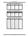
Transmitter measurements
RF Frequency Meter
Frequency Range
400 kHz to 1.05 GHz (manual tune)
10 MHz to 1 GHz (auto-tune)
Resolution
1 Hz or 10 Hz, selectable, <1050 MHz
0.1 Hz, 1 Hz, 10 Hz up to 999 MHz
Indication
Up to 10 digits
Accuracy
As frequency standard ±resolution
Acquisition Time
Less than 1 second (manual).
Typically 3 seconds (autotune)
Sensitivity
Autotuned: 5 mW (N-Type) 0.05 mW BNC (antenna port)
Manual Tuned: −34 dBm (N-Type), −60 dBm BNC (antenna
port)
Auto or manual control of input attenuator
VSWR
N Type
<1.2:1 to 500 MHz
<1.25:1 to 1.05 GHz
BNC (antenna port)
<3:1 to 1.05 GHz
RF Power Meter (Broadband)
Frequency Range
200 kHz to 1.05 GHz
Dynamic Range
5 mW to 150 W (N-Type)
0.05 mW to 250 mW BNC (antenna port)
Indication Units
Watts, dBm or dBW
Indication
3 digits or barchart
Resolution
0.1 dB, typically 1%
Accuracy
±10 % ±resolution up to 1 GHz (FM and CW)
Maximum Continuous Rating
N-Type: 50W at 20°C
BNC output: 5 W
Antenna port: 1 W
Intermittent Rating
N-Type: 150 W for limited periods, typically 1 minute at 20°C
Overload indicated by audible and visual warning
Harmonic Measurement
Displays 1st to 5th harmonic of the carrier
Max. harmonic frequency
1.05 GHz
Dynamic range
0 to −60 dBc (depends on filter b/w selected)
Transient Power Analysis
Displays power profile against time
Frequency range
1 to 1.05 GHz
Dynamic range
60 dB below spectrum analyzer reference level
Scale (power)
10 dB/div
Scale (time)
50 μs/div to 5 s/div
Trigger level
Adjustable over full dynamic range +ve or −ve trigger
Pre-trigger
0, 25%, 50%, 75% or 100% of displayed period
1-11
GENERAL INFORMATION
Modulation Meter
Sensitivity
Autotuned: 5 mW (N-Type) 0.05 mW BNC (antenna port)
Manual Tuned: −34 dBm (N-Type) −60 dBm BNC (antenna port)
Auto or manual control of input attenuator
Audio Filters
Lowpass Filters
Four independently configurable Lowpass filters LP1, LP2, LP3,
LP4 that can be set to any frequency cut-off point from 250 Hz
to 20,000 Hz (excluding the band 1001 to 2999 Hz).
A 50 kHz Lowpass (No filters applied).
750 µs de-emphasis.
Highpass Filters
50 Hz Highpass
300 Hz Highpass
Bandpass Filters
Any combination of LP1, LP2, LP3, LP4 and the Highpass filters.
Amplitude Modulation
Frequency Range
400 kHz to 1.05 GHz
Modulation Frequency Range
10 Hz to 15 kHz
0 to 99 % (manually tuned)
0 to 90 % below 100 MHz
0 to 80 % from 100 to 400 MHz
Peak hold facility
AM Depth Range
Resolution
1% AM
Indication
2 digits and barchart
Accuracy †
± 5% ±1 digit at 1 kHz
± 8.5% ±1 digit 50 Hz to 10 kHz
Demodulation distortion
Less than 2 % at 1 kHz and 30 % AM (CCITT weighted)
Residual AM
Less than 1 % (300 Hz to 3.4 kHz)
Frequency Modulation
Frequency Range
400 kHz to 1.05 GHz
Modulation Frequency Range
10 Hz to 15 kHz
Deviation Range
0 to 75 kHz peak
Resolution
10 Hz below 2 kHz deviation,
1% above 2 kHz deviation
Indication
3 digits and barchart
± 5 % ±resolution at 1 kHz modulation frequency
± 7.5% ±resolution 50 Hz to 10 kHz
Accuracy †
Demodulation distortion
Less than 2 % at 1 kHz and 5 kHz FM (CCITT weighted)
Residual FM
Less than 30 Hz (300 Hz to 3.4 kHz)
Demodulation Output Socket
200 mV peak to peak ±10 % per 1 kHz deviation
† At low modulation levels the residual AM / FM may become significant
1-12
GENERAL INFORMATION
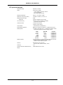
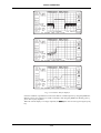
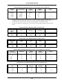
RF spectrum analyzer
Frequency Range
400 kHz to 1.05 GHz
Spans
Continuously variable,
1 kHz / division to 100 MHz / division
1,2,5,10 increments
Start / Stop frequency entry
Resolution Bandwidth
300 Hz, 3, 30, 300 kHz, 3 MHz
Reference Level (top of screen)
−50 dBm to +52 dBm, 0.7 mV to 71 V
Displayed dynamic range
80 dB
Noise floor
Typically 75 dB below top of screen
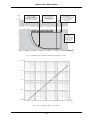
On screen linearity
Typically ± 2 dB ±1 resolution (10 dB/div)
(10 dB above the noise floor)
Vertical resolution
0.1 dB on 2 dB / division
0.5 dB on 10 dB / division
Level Flatness
± 2 dB ±resolution (10 dB/division)
Intermodulation Distortion
Better than 70 dB for two signals at −30 dBm into first mixer
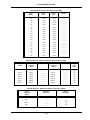
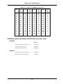
Sweep speeds
10 ms/div to 200 ms/div in a 1, 2, 5 sequence (optimum sweep
speed and bandwidth selected according to span)
SPAN
10 kHz
100 kHz
1 MHz
10 MHz
100 MHz
1000 MHz
RES B/W
UPDATE
300 Hz
3 kHz
30 kHz
300 kHz
300 kHz
3 MHz
5 SWEEP/sec
9 SWEEP/sec
9 SWEEP/sec
9 SWEEP/sec
5 SWEEP/sec
5 SWEEP/sec
Marker Indication
Level and frequency or delta marker from center line of screen
Single marker for frequency and level display
Marker to center frequency marker
Features
Simultaneous 'Look and Listen'
Span 100 kHz, 200 kHz, 500 kHz, 1 MHz
Sensitivity
2 μV
Tracking Generator Offset/Frequency
Range
0-999 MHz/400 kHz to 1 GHz
1-13
GENERAL INFORMATION
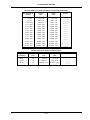
Audio generators
Frequency
Frequency Range
5 Hz to 33 kHz
Wave shape
Sine or square
Setting
Keyboard entry, delta increment / decrement function
and rotary control
Indication
5 digits
Resolution
0.1 Hz below 3.25 kHz
1 Hz above 3.25 kHz
Accuracy
0.01 Hz <180 Hz
0.1 Hz >180 Hz
Level
Range
0.1 mV to 4 V RMS
Setting
Keyboard entry, delta increment / decrement function
and rotary control
Indication
4 digits
Resolution
0.1 mV below 409 mV
1 mV above 409 mV
Accuracy
±5% ±resolution 50 Hz - 15 kHz
Output impedance
Nominally 5 Ω (Minimum load impedance 25 Ω)
Distortion
Less than 0.5 % at 1 kHz
Less than 1 % from 50 Hz to 15 kHz
Signaling Encoder / Decoder
Sequential Tones Functions
Sequential tones functions including revert User defined tones
Encodes and decodes up to 40 tones.
CCIR, ZVEI, DZVEI, EEA, EIA or user defined.
Any of the tones may be extended.
Continuous, burst and single step modes available.
User Defined Tones
Up to two sequential tones frequency plans may be defined and
stored within the Service Monitor. Any of the standard tone
frequency plans may be copied to user defined and modified.
Tone length 20 ms to 20 s
Standard tone frequencies may be selected from a menu
DTMF
Generation and decoding of DTMF tones
DCS
Generation and decoding of Digitally Coded Squelch, DCS
POCSAG
Generation of POCSAG code CCIR No. 1 Rec 584. Bit rates
from 400 to 4800 bit/s. Inversion available.
Audio Monitor
Demodulated signals and audio signals may be monitored via the
internal loudspeaker and via the accessory socket output on
the front panel.
1-14
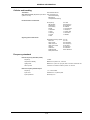
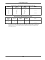
GENERAL INFORMATION
Cellular and trunking
Test Modes
Auto test/manual test
Auto Test Programs (dependent upon which Call processing only
system is in use)
Call and RF testing
Brief testing
Comprehensive testing
Parametric Auto Test Routines
AF frequency
FM deviation
Rx distortion
Rx sensitivity
Rx S/N
Tx distortion
Tx level
Tx limiting
Tx noise
Tx S/N
AF Level
Mod frequency
Rx expansion
Rx SINAD
Tx compression
Tx frequency
Tx power level
Tx mod level
Tx SINAD
Registration/roaming update
Place call
Page mobile
Clear from land
Clear from mobile
Handoff
Hook flash
DTMF decode
Data performance
PTT on
PTT off
SAT deviation
SAT frequency
ST duration
ST frequency
ST deviation
DSAT deviation
Signaling Auto Test Routines
Frequency standard
Internal Frequency Standard (OCXO)
Frequency
10 MHz
Temperature stability
Better than 5 parts in 10 , 0 to 55°C
Ageing Rate
Better than 1 part in 10 per year, after 1 month's continuous use.
Warm up time
Less than 10 minutes to within 2 parts in 10 at 20°C
8
7
7
External Frequency Standard Input
Frequency
1, 2, 5 and 10 MHz
Input Level
Greater than 1 V peak to peak
Input Impedance
Nominally 1 kΩ
1-15
GENERAL INFORMATION
General
General features
Keyboard and Display`
Display size
Logical color-coded keyboard with bright high resolution LCD
160 x 85 mm
RS232C interface is provided for printing or remote Service
Monitor control.
RS232C
Connector
9 way female 'D' Type
Power Requirements
AC Supply Voltage
100 to 240V~
(limit 90 V to 264 V~)
108 to 118V~
(Limit 98 V to 132 V~)
AC Supply Frequency
50 to 60 Hz
(limit 45 Hz to 66 Hz)
50 to 400 Hz
(limit 45 Hz to 440 Hz)
Maximum AC Power
190 VA
DC Supply Voltage
11 to 32V
Maximum DC Power
100 W
Calibration Interval
2 Years
Electro-Magnetic Compatibility
Conforms with the protection requirements of the EC Council
Directive 2004/108/EC
Conforms with the limits specified in the following standards:
IEC/EN 61326-1 : 1997 + A1 : 1998 + A2 : 2001 + A3 : 2003,
RF Emission Class B, Immunity Table 1, Performance
Criterion B
Safety
Conforms with the requirements of EC Council Directive
2006/95/EC (as amended) and the product safety standard
IEC/EN 61010-1 : 2001 + C1 : 2002 + C2 : 2003 for Class 1
portable equipment, for use in a Pollution Degree 2
environment. The instrument is designed to operate from an
Installation Category 2 supply.
Environmental
Rated range of use
0°C to +55°C and up to 95% relative humidity at 40°C
Storage and transport
Temperature
−30°C to +71°C
Altitude
Up to 2500m (pressurized freight at 27 kPa differential)
Dimensions and Weight
Standard dimensions
Height
178 mm (7 inches)
Width
380 mm (15 inches)
Depth
457 mm (18 inches) (including handle, feet and covers)
Weight
Less than 12 kg (Less than 27 lb)
with no options fitted
1-16
GENERAL INFORMATION
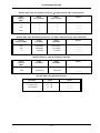
Options and accessories
Options
Option 1
Option 2
Option 4
Option 5
Option 6
Option 8
Option 9
Option 10
Option 11
Option 12
Option 13
Option 14
Option 15
Option 16
600 Ω Matching Unit
Analog Systems Card
Parallel Interface †
GPIB Interface †
Memory Card Drive and Date/Time Stamp
SSB Demodulator
Occupied Bandwidth
NMT
AMPS
TACS
MPT1327
Require Option 2 to be fitted
PMRTEST
EDACS Radio Test
EDACS Repeater Test
Option 22
Option 23
Option 24
Option 25
Option 26
Option 29
Option 30
Option 31
POCSAG decode
CCITT Filter ‡
CMESS Filter ‡
Avionics
Tones Remote
Plus 2 Distortion Notch Filters board
Bail arm and front panel stowage cover
IF Output Capability
⎫
⎪
⎬
⎪
⎭
† Option 4 and Option 5 cannot both be fitted.
‡ Option 23 and Option 24 cannot both be fitted.
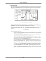
600 Ω Matching Unit (Option 1)
Features
Switchable 600 Ω balanced AF input and output
Switchable 20 dB attenuator on AF generator output †
Input circuit
Impedance:
600 Ω
Return loss:
>21 dB at 1 kHz
Frequency response:
±0.5 dB at 200 Hz to 5 kHz,
±2 dB at 100 Hz to 20 kHz
Accuracy of 1:1 input:output ratio: ±1% at 1 kHz ± accuracy of 2948B
Maximum input:
5 V RMS maximum at 200 Hz to 5 kHz,
3 V RMS maximum at 100 Hz to 20 kHz
Output circuit
Impedance:
600 Ω
Return loss:
>21 dB at 1 kHz
Frequency response:
±0.5 dB at 200 Hz to 5 kHz,
±2 dB at 100 Hz to 20 kHz
Level accuracy:
±2% at 1 kHz ± accuracy of 2948B
Output level:
1 mV to 2.5 V RMS across 600 Ω.
† The 20 dB attenuator facility reduces the AF output resolution to 0.01 mV up to 40 mV output level.
The accuracy of the output level degrades by ± 2 %
Analog Systems Card (Option 2)
Required for Options 10 to 16.
For performance data refer to respective handbook supplement.
1-17
GENERAL INFORMATION
Parallel Interface (Option 4)
Allows direct connection of a parallel printer. Additionally
provides 4 software programmable output lines.
Printer port
Connector
25 way female D-type
Printers supported
75,100,150 dots per inch laser printers
FX80, FX100 Epson format.
Accessory port
Connector
9 way female D-type
Outputs
4 independently programmable output lines, each one
configurable as a logic line or as a relay contact closure.
+5V supply available.
GPIB (Option 5)
For remote control of the Service Monitor.
Complies with the following subsets defined by IEEE488:SH1, AH1, T6, L4, SR1, RL1, E1, DC1, DT0
Capability
Memory Card Drive and Real Time Clock
(Option 6)
The memory card facility allows the storage of results, set-ups,
screen dumps and user programs. Meets PCMCIA 2 standard.
Allows the current date and time to be stored with results to the
memory card and/or printed with a screen dump.
SSB Demodulator (Option 8)
The SSB demodulator allows signals to be demodulated either
via the internal loudspeaker or via the accessory socket.
Provides demodulation of SSB signals (upper and lower
sideband.)
Frequency range
400 kHz to 1 GHz
AF demodulation range
10 Hz to 15 kHz
Distortion
Typically less than 3% at 1 kHz (300 Hz to 3.4 kHz)
Detection range
2 μV to 150 W
Features
Automatic detection of USB or LSB.
BFO can be used for tuning of carrier for AM and FM radios.
Calculates the bandwidth of a signal displayed on the spectrum
analyzer.
Occupied Bandwidth (Option 9)
Frequency range
1 MHz to 1 GHz
Displayed resolution
3 digits
Accuracy
20%
Bandwidth measurement range
3 kHz minimum
Ratio range
90% to 99%, selectable in 0.1% steps
NMT Cellular Software (Option 10)
NMT 450
NMT 900
Benelux
NMTF
Austria
Spain
Malaysia
Indonesia
Saudi 1
Saudi 2
Thailand
Oman
Tunisia
Hungary
Poland
Russia
Czech
Bulgaria
Slovenia
Turkey
USER DEFINED NMT
AMPS Cellular Software (Option 11)
E-AMPS
N-AMPS
USER DEFINED AMPS
TACS Cellular Software (Option 12)
E-TACS
TACS 2
C-TACS II
J-TACS
USER DEFINED TACS
MPT 1327 Trunking Software (Option 13)
BAND III
UK WATER
AUTONET
MADEIRA
NZ MPT1327
USER DEFINED MPT
1-18
C-TACS I
N-TACS
JRC
HONG KONG
AMT
NL-TRAXIS
PH-INDO
GENERAL INFORMATION
PMRTEST Software (Option 14)
USER DEFINED PMR for FM radios
EDACSTM Radio Test Software (Option
15)
Provides Auto/Manual test capability for EDACS™ radios. Up to
four user-defined variants can be created and stored, each with
up to 24 spot-channel frequencies
EDACSTM Repeater Test Software (Option Provides Auto/Manual test capability for EDACS™ repeaters. Up
to four user defined variants can be created and stored, each with
16)
up to 24 spot-channel frequencies. A data logging facility is also
available to continuously decode and display data messages from
the repeater under test.
EDACS is an Ericsson GE registered trademark.
LTR Trunking Test Software (Option 18)
Provides Auto/Manual test capability for LTR Trunked radios
Pocsag Decode (Option 22)
Allows off-air decoding of POCSAG messages. Can decode a
message as it is received, or decoding can be triggered from a
user-selectable RIC code or fixed message pattern.
Bit Rate
Automatically decodes any standard bit rate up to 4800 bit/s.
Numeric and Alphanumeric decoding is provided.
Number of received errors is displayed.
CCITT (Option 23)
Allows a CCITT filter to be inserted into either the demodulated
audio path or the audio input path
C-MESSAGE (Option 24)
Allows a CMESS filter to be inserted into either the demodulated
audio path or the audio input path
Avionics (Option 25)
The Avionics Systems provides amplitude modulated signals
suitable for testing ILS, VOR, Marker Beacons and SELCAL
Full details of the Avionics features can be found in the Option 25
data sheet , part number 46891/213
Tone Remote Option 26)
Provides configuration screens and generation of Tone Remote
control signals.
Plus 2 Distortion Notch Filters board
(Option 29)
The standard instrument is supplied with a 1 kHz notch for
Distortion and SINAD measurements. This option allows the user
to carry out Distortion and SINAD measurements at two additional
frequencies. The two additional notch frequencies can be
anywhere in the band 50 Hz to 20 kHz and must be stipulated at
the time of ordering.
Bail arm and front panel stowage cover
(Option 30)
Provides a bail arm carrying handle and front panel cover and
storage area. The bail arm will also provide additional viewing
angles when mounted on a bench.
IF Output Capability (Option 31)
Allows access to the IF signal from the rear of the Instrument.
(Note: Incorporation of this option replaces the standard demod
out capability.)
1-19
GENERAL INFORMATION
Supplied Accessories
43138/755
46882/692
46882/683
AC Supply lead*
DC Supply lead
Operating Manual
Programming Manual
*The AC supply lead provided with the Service Monitor will depend on
the destination country. See Power requirements, Power cords, in
chapter 2 of this manual
Optional Accessories
44991/145
54431/023
46884/728
54421/001
46662/779
46662/571
46662/616
54112/163
46880/115
54421/002
54421/003
43130/590
43130/591
59999/170
59000/189
59000/375
46884/648
46884/649
46884/650
80013
1-20
Microphone with PTT
20 dB AF attenuator (BNC)
Rack Mounting Kit
Antenna BNC
Soft carrying case (suitable for all 2948/2948B)
Soft carrying/operational case
Soft carrying/operational case for use with Option 30
Hard transit case
Service Manual
Directional Power Head 1 to 50 MHz
Directional Power Head 25 to 1000 MHz
1m 7 way DIN lead Assy
3m 7 way DIN lead Assy
RF Directional Bridge
Memory Card (128kbyte)
Memory Card (2Mbyte)
Serial cable 9 way female to 25 way male
Serial cable 9 way female to 25 way female
Serial cable 9 way female to 9 way female
Cable assembly N (m) to N (m), 2.5 m,
double-screened
GENERAL INFORMATION
EC Declaration of Conformity
Certificate Ref. No.: DC256
The undersigned, representing:
Manufacturer:
Aeroflex International Ltd.
Address:
Longacres House, Six Hills Way,
Stevenage, Hertfordshire, UK SG1 2AN
Herewith declares that the product:
Equipment Description:
Model No.
Communications Service Monitor
2948B
1, 2, 4, 5, 6, 8, 9, 10, 11, 12, 13, 14, 15, 16, 18, 22, 23, 24, 25, 26, 29, 30, 31,
soft carrying/optional case and microphone
Options:
is in conformity with the following EC directive(s)
(including all applicable amendments)
Title:
Reference No.
2006/95/EC
Low Voltage Directive
2004/108/EC
EMC Directive
and that the standards and/or technical specifications referenced below have been applied:
Safety:
Designed to:
IEC/EN 61010-1 : 2001 + C1 : 2002 + C2 : 2003
EMC:
IEC/EN 61326-1:1997 + A1 : 1998 + A2 : 2001+ A3 : 2003
RF Emission Class B, Immunity Table 1 and Performance Criterion B
Qualifying Notes:
Aeroflex Stevenage (Place)
(Signature)
Richard Dickens - Quality Manager
1-21
3 September 2007
(Date)
Chapter 2
INSTALLATION
Contents
Introduction.................................................................................................................................... 2-2
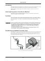
Initial visual inspection of new Service Monitors.......................................................................... 2-2
Ventilation ..................................................................................................................................... 2-2
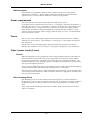
Operational case (46662/571) shoulder strap................................................................................. 2-2
Bail arm option ....................................................................................................................... 2-3
Power requirements ....................................................................................................................... 2-3
Fuses .............................................................................................................................................. 2-3
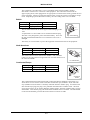
Class I power cords (3-core) .......................................................................................................... 2-3
Connecting to a DC supply ............................................................................................................ 2-6
RF and AF connections.................................................................................................................. 2-6
Accessory socket connections........................................................................................................ 2-7
Remote control connections........................................................................................................... 2-8
RS232 ..................................................................................................................................... 2-8
GPIB ....................................................................................................................................... 2-9
Self tests................................................................................................................................ 2-10
Positioning the Service Monitor for use ...................................................................................... 2-11
Routine maintenance.................................................................................................................... 2-11
Ventilation fan and filter....................................................................................................... 2-11
Routine safety testing and inspection........................................................................................... 2-12
1. Visual inspection ............................................................................................................. 2-12
2. Earth bonding tests .......................................................................................................... 2-12
3. Insulation tests ................................................................................................................. 2-13
4. Rectification..................................................................................................................... 2-13
Cleaning................................................................................................................................ 2-13
List of tables
Table 2-1 Accessory socket pin numbering, location and functions............................................. 2-7
Table 2-2 Accessory socket logic and applications ...................................................................... 2-8
List of figures
Fig. 2-1
Fig. 2-2
Fig. 2-3
Fig. 2-4
Fig. 2-5
Preventing strap buckle from slipping............................................................................. 2-2
Accessory in/out socket pin numbers .............................................................................. 2-7
RS232 serial port connections......................................................................................... 2-8
Null modem connections................................................................................................. 2-9
IEEE488 parallel port connections.................................................................................. 2-9
2-1
INSTALLATION
Introduction
This chapter deals with preparing the Service Monitor for use for the first time and with the checks
to be made when the Service Monitor may have been used under unknown conditions.
The latter situation could well apply where the Service Monitor is used by several users for
differing tasks.
Initial visual inspection of new Service Monitors
After unpacking the Service Monitor and before making any connections to a power source,
inspect for any signs of mechanical damage.
Ventilation
The Service Monitor is force cooled by a fan located in the rear panel. The cooling air is drawn
into the Service Monitor through the fan and expelled through ventilator grills located on the right
and on the underside. An air filter over the fan inlet prevents the ingress of dust and other
particles.
The Service Monitor requires an unrestricted airflow to ensure that its performance meets
the specification. Before switching the Service Monitor on, check that the air inlet on the
rear panel is not restricted and that there is no loose material close by which could be
sucked into the fan. Refer to Routine Maintenance later in this chapter for details of
cleaning and replacing the air filter.
The optional operational case has ventilation apertures which align with those of the
Service Monitor. Ensure that these are not obstructed.
Operational case (46662/571) shoulder strap
The shoulder strap supplied with the operational case should be attached to the front handles of the
Service Monitor. When fitting the strap, always loop the tails of the strap through the buckles in
the reverse direction. This will prevent the strap from slipping through the buckle. See Fig. 2-1
Preventing strap buckle from slipping.
STRAP
BUCKLE
HANDLE
C2509
Fig. 2-1 Preventing strap buckle from slipping
2-2
INSTALLATION
Bail arm option
If the bail arm carrying handle is fitted, the Service Monitor will not fit into the optional
operational case, 46662/571. Do not attempt to attach the shoulder strap supplied with this
operational case to a Service Monitor fitted with a bail arm carrying handle.
Power requirements
The Service Monitor can be powered from both AC and DC power sources.
AC supplies must be within the range 100 to 240 V~, at a frequency of between 50 and 60 Hz; or
within the range 108 to 118 V~, at a frequency of between 50 and 400 Hz. The maximum power
consumption is 190 VA. Voltage selection is not necessary as the AC power supply module
within the Service Monitor is designed to handle this wide spread of input variations. For DC
operation, the Service Monitor requires a supply within the range 11 to 32 V. The maximum DC
power requirement is 100 W.
Fuses
The AC input circuit is fed through a single fuse fitted to the rear panel of the Service Monitor,
within the AC input connector. This should be a 2 A anti-surge, 5 × 20 mm glass cartridge fuse,
type T2AL250V.
The DC input circuit is also fed through a single fuse fitted to the rear panel of the Service
Monitor. This should be a 10 A anti-surge, 5 × 20 mm glass cartridge fuse, type T10AH250V.
Class I power cords (3-core)
General
When the equipment has to be plugged into a Class II (ungrounded) 2-terminal socket outlet, the
cable should either be fitted with a 3-pin Class I plug and used in conjunction with an adapter
incorporating a ground wire, or be fitted with a Class II plug with an integral ground wire. The
ground wire must be securely fastened to ground. Grounding one terminal on a 2-terminal socket
will not provide adequate protection.
In the event that a molded plug has to be removed from a lead, it must be disposed of immediately.
A plug with bare flexible cords is hazardous if engaged in a live socket outlet.
The instrument is a Safety Class 1 product and therefore must be earthed. Use the supplied power
cord or an appropriate replacement. Make sure that the instrument is plugged into an outlet socket
with a protective earth contact.
Disconnecting device
The detachable power cord is the instrument’s disconnecting device, but if the instrument is
integrated into a rack or system, an external power switch or circuit breaker is required. Whatever
the disconnecting device, make sure that you can reach it easily and that it is accessible at all
times.
Power cords with the following terminations are available. Please check with your local sales
office for availability.
2-3
INSTALLATION
This equipment is provided with a 3-wire (grounded) cordset which includes a molded
IEC 60320-1 connector for connection to the equipment. The cable must be fitted with an
approved plug which, when plugged into an appropriate 3-terminal socket outlet, grounds the case
of the equipment. Failure to ground the equipment may expose the operator to hazardous voltage
levels. Depending upon the destination country, the color coding of the wires will differ:
British
Country
IEC 60320-1 plug
Part number
United Kingdom
Straight through
23422/001
United Kingdom
Right angled
23422/002
EARTH
The UK lead is fitted with an ASTA approved molded plug to BS
1363.
A replaceable 13 A fuse to BS 1362 is contained within the plug.
This fuse is only designed to protect the lead assembly. Never use
the plug with the detachable fuse cover omitted or if the cover is
damaged.
NEUTRAL
LIVE
UNITED KINGDOM
C3510
The fuse(s) or circuit breaker to protect the equipment is fitted at the back of the equipment.
North American
Country
IEC 60320-1 plug
Part number
North American
Straight through
23422/004
North American
Right angled
23422/005
EARTH
The North American lead is fitted with a NEMA 5-15P (Canadian
CS22.2 No 42) plug and carries approvals from UL and CSA for use in
the USA and Canada.
LIVE
NEUTRAL
U.S./CANADA/KOREA
Continental Europe
Country
C3511
IEC 60320-1 plug
Part number
EARTH
Europe
Straight through
23422/006
Europe
Right angled
23422/007
LIVE
NEUTRAL
EARTH
CONTINENTAL
EUROPE
C3512
The Continental European lead is fitted with a right angle IEC83 standard C4 plug (CEE 7/7)
which allows it to be used in sockets with either a male earth pin (standard C 3b) or side earth
clips (standard C 2b) the latter is commonly called the German ‘Schuko’ plug. In common with
other Schuko style plugs, the plug is not polarized when fitted into a Schuko socket. The lead
carries approvals for use in Austria, Belgium, Finland, France, Germany, Holland, Italy, Norway
and Sweden. Note that this plug will not fit Italian standard CEI 23-16 outlets. The lead should
not be used in Denmark given that the earth connection will not be made.
2-4
INSTALLATION
Français
Le câble d'alimentation d'Europe Continentale est muni d'un connecteur mâle à angle droit type
CEI83, standard C4 (CEE 7/7), qui peut être utilisé dans une prise femelle à ergot de terre
(standard C 3b) ou à clips latéraux (standard C 2b), cette dernière étant communément appelée
prise “Schuko” allemande. De la même façon que les autres connecteurs de type Schuko, celui-ci
n'est pas polarisé lorsqu'il s'adapte à une prise femelle Schuko. Ce câble d'alimentation est
homologué en Allemagne, Autriche, Belgique, Finlande, France, Hollande, Italie, Norvège et
Suède. A noter que ce connecteur n'est pas compatible avec les prises de courant italiennes au
standard CEI 23-16. Ce câble ne doit pas être utilisé au Danemark à cause du défaut de connexion
de masse.
Deutsch
Das kontinentaleuropäische Netzkabel ist mit einem rechtwinkeligen Stecker nach IEC83 C4
(CEE7/7) Standard versehen, welcher sowohl in Steckdosen mit Erde-Stift (Standard C 3b) oder
seitlichen Erdeklemmen, im allgemeinen “Schukosteckdose” genannt, paßt. Üblicherweise ist der
Schukostecker bei Verwendung in Schukosteckdosen nicht gepolt. Dieses Netzkabel besitzt
Zulassung für Österreich, Belgien, Finnland, Frankreich, Deutschland, Holland, Italien, Norwegen
und Schweden.
Hinweis: Dieser Schukostecker paßt nicht in die italienischen Standardsteckdosen nach CEI 23-16
Norm. Dieses Netzkabel sollte nicht in Dänemark verwendet werden, da hier keine
Erdeverbindung hergestellt wird.
Español
El cable de alimentación tipo Europeo Continental dispone de una clavija C4 normalizada IEC83
(CEE 7/7) que permite su utilización tanto en bases de enchufe con toma de tierra macho (tipo C
3b) o con toma de tierra mediante contactos laterales (tipo C 2b) que, en este último caso, suele
denominarse “Schuko”. Al igual que cualquier otra clavija tipo Schuko, las conexiones a red no
están polarizadas cuando se conectan a una base tipo Schuko. El cable lleva autorización para su
uso en Austria, Bélgica, Finlandia, Francia, Alemania, Holanda, Italia, Noruega y Suecia.
Observe que este cable no se adapta a la norma italiana CEI 23-16. El cable no debe utilizarse en
Dinamarca en el caso de no efectuarse conexión a tierra.
Italiano
I cavi d'alimentazione per l'Europa continentale vengono forniti terminati con una spina ad angolo
retto del tipo C4 secondo lo standard IEC83 (CEE 7/7) che può essere usato in prese in cui la terra
può essere fornita o tramite connettore maschio (C 3b) o tramite clips laterali (C 2b), quest'ultima
comunemente detta di tipo tedesca “Schuko”. Questa spina, quando collegata ad una presa
Schuko, non è polarizzata.
Il cavo può essere usato in Austria, Belgio, Finlandia, Francia, Germania, Olanda, Norvegia,
Svezia ed Italia. E' da notare che per l'Italia questo non risponde allo standard CEI 23-16.
Questa spina non dovrebbe invece essere usata in Danimarca in quanto non realizza il
collegamento di terra.
2-5
INSTALLATION
Connecting to a DC supply
If the Service Monitor is to be used from a DC voltage source it should be connected using the
supplied DC connecting lead. The polarity of the connections must be correct, RED to
POSITIVE, BLACK to NEGATIVE.
The negative connection of the DC supply is directly connected to the chassis of the Service
Monitor and therefore to all screen connections of input and output connectors. Note however,
that the AF ports are isolated under some operating conditions.
The Service Monitor will function from any supply with a voltage within the range given under
Performance data, Power requirements, in chapter 1. Note that the supply must be capable of
delivering a current in the order of 9 amps at the lowest voltage.
Ensure that the supply lead connections are sound and cannot short together.
If the DC supply powering the Service Monitor falls to a level close to the lower limit of the input
voltage range, a warning BAT is displayed on the screen.
RF and AF connections
All RF and AF connections should made using good quality connectors correctly fitted to
appropriate cable. All connectors should be locked to the Service Monitor using the bayonet or
threaded locking rings. Do not use leads that have damaged connectors or cable as this can cause
poor performance and might damage the Service Monitor.
RF leakage levels in a test set-up can be aggravated by the use of poor quality connector leads. A
double screened lead, 1 meter in length and terminated with male BNC connectors, Part No
43137/052 and a 1 meter, 'N type' male to `N type' male, connector lead 54311/095 are both
available from Aeroflex sales offices.
WARNING
Hot Surfaces
Take care when touching the RF Input Type N connector after the application of high levels of
continuous power. If 50 W is exceeded for a prolonged period, the temperature of the connector
can become excessive.
2-6
INSTALLATION
Accessory socket connections
The accessory socket located on the front panel, is of the 7 pin DIN, 45° configuration.
The function of each of the pins on this socket is shown in the following table. The pin numbering
is shown in Fig. 2-2 Accessory in/out socket pin numbers, and is as viewed from the front of the
Service Monitor.
Table 2-1 Accessory socket pin numbering, location and functions
Din pin No
Function
6
Logic
1
Mic input/PTT-logic
4
Forward power
2
12 V DC at approx. 100 mA
5
Reverse power
3
Logic
7
Loudspeaker output
The pin numbering of the Accessory socket, as seen from the front of the Service Monitor, is
shown in Fig. 2-2 Accessory in/out socket pin numbers.
2
4
5
1
3
6
7
EARTH SHIELD
C1785
Fig. 2-2 Accessory in/out socket pin numbers
The socket is used for connecting dedicated accessories such as directional power heads and
microphones with press to talk switching capabilities.
2-7
INSTALLATION
Selection logic [or data signals] on pins 1, 3 and 6 enables the Service Monitor to recognize the
connections of an external accessory. The appropriate pins are at TTL levels and are active low as
shown below:
Table 2-2 Accessory socket logic and applications
Accessory
Pin 1
Pin 3
Pin 6
Nothing connected
High
High
High
Microphone (press to talk)
low
high
high
External power: Auto zero
High
Low
Low
External power: Peak power
High
High
Low
External power: CW power
High
Low
High
Refer to chapter 3, Operation, for details of using the socket.
A 3.0 meter lead assembly (part No. 43130/591) is available as an optional accessory.
Remote control connections
RS232
The serial port connection requires a 9 way female ‘D’ Type connector. This should be correctly
fitted to the appropriate cable and the locking screws should be used to prevent undue strain from
being applied to the connector housing.
The pin connections are listed below and the pin locations shown in Fig. 2-3 RS232 serial port
connections (as seen facing panel).
Contact
1
2
3
4
5
Function
Contact
Not connected
Rx data in
Tx data out
DTR
Ground
6
7
8
9
1
Function
DSR
RTS
CTS
Not connected
5
C0783
6
9
Fig. 2-3 RS232 serial port connections (as seen facing panel)
The use of a NULL MODEM cable assembly is required for connecting to control equipment such
as PCs.
The connections for 9 way to 9 way and 9 way to 25 way versions are shown in Fig. 2-4.
2-8
INSTALLATION
SERVICE
MONITOR
PC
SERVICE
MONITOR
PC
9-WAY
9-WAY
9-WAY
25-WAY
SG
5
5
SG
SG
5
7
SG
RXD
2
2
RXD
RXD
2
3
RXD
TXD
3
3
TXD
TXD
3
2
TXD
DTR
4
4
DTR
DTR
4
20 DTR
NOT
CONNECTED
1
1
DCD
NOT
CONNECTED
1
8
DCD
DSR
6
6
DSR
DSR
6
6
DSR
RTS
7
7
RTS
RTS
7
4
RTS
CTS
8
8
CTS
CTS
8
5
CTS
NOT
CONNECTED
9
NOT
CONNECTED
9
C3383
Fig. 2-4 Null modem connections
GPIB
When the optional GPIB interface unit has been fitted, connections are made to it using a 24-way
IEEE 488 male connector. If a stackable connector is used in order to interconnect more than two
pieces of equipment, ensure that no physical damage to the Service Monitor connector will result.
The pin connections are listed below and the pin locations shown in Fig. 2-5 IEEE488 parallel
port connections (as seen facing panel).
Contact
1
2
3
4
5
6
7
8
9
10
11
12
Function
Data I/O 1
Data I/O 2
Data I/O 3
Data I/O 4
EOI
DAV
NRFD
NDAC
IFC
SRQ
ATN
Ground shield
Contact
13
14
15
16
17
18
19
20
21
22
23
24
12
1
24
13
Function
Data I/O 5
Data I/O 6
Data I/O 7
Data I/O 8
REN
Pair with 6
Pair with 7
Pair with 8
Pair with 9
Pair with 10
Pair with 11
Logic ground
C0683
Fig. 2-5 IEEE488 parallel port connections (as seen facing panel)
2-9
INSTALLATION
Self tests and acceptance tests
The service monitor incorporates a self test program which allows users to verify its condition at
any time. This program is described below.
When it is necessary to prove that the performance of the Service Monitor meets the published
performance data, the Acceptance tests, described in Chapter 5, should be carried out.
Self tests
The built in Self Test program measures the output parameters of the RF generator using the
transmitter test functions. The RF generator output is coupled internally and no external
connections are required.
The self test program is accessed through the help/set-up menu and consists of 17 tests, which are
listed on the display when the [Self Test] key is pressed.
Before running the program, the Service Monitor should be reset to the factory preset state. This
is done by pressing the [MEM] key, to display the STORE/RECALL screen and menu. The
message 'Recall Store No' is shown. Key in and enter the digits '01'. The Service Monitor will
now be ready to run the self test program.
To run the program the [GO] key is pressed and the tests are carried out consecutively. The
legend ‘ACTIVE’ is displayed against each test as it is carried out, which changes to ‘PASS’ or
‘FAIL’ as each test is completed. If a particular test fails, the reason is given alongside the ‘FAIL’
legend, together with the measurement.
The tests carried out, the related set-ups and the functions verified are listed below.
Test No 1
Broadband power. 500 MHz
Test No 2
Transmitter Frequency. 500
MHz
Test No 3
Broadband power. 1 GHz
Test No 4
Transmitter Frequency. 1 GHz
Test No 5
Broadband power. 10 MHz
Test No 6
Transmitter Frequency. 10 MHz
The above tests compare the generated power and frequency against the broadband power meter
and the frequency meter at each of the frequencies specified.
Related set-up. Manual tune
The functions verified by the above tests are:Signal generator frequency and level accuracy.
Power meter accuracy.
Test No 7 to 14
Narrow band power meter. Power level +10 dBm. (Test No 7) to -60 dBm. (Test No 14)
These tests compare the generated power levels against the narrowband power meter readings.
Related set-ups. Frequency, 10 MHz, IF Bandwidth, 30 kHz.
The functions verified by the above tests are:Signal generator level accuracy.
Signal generator attenuators.
Spectrum analyzer level accuracy.
Receiver attenuators.
2-10
INSTALLATION
Test No 15
FM deviation. 50 kHz
This test checks the signal generator FM deviation against the modulation meter reading.
Related set-ups. Frequency 10 MHz, level -26 dBm, IF bandwidth 300 kHz, audio bandwidth
0.3 - 3.4 kHz, FM demodulation.
The functions verified by the above tests are:Signal generator FM accuracy, modulation meter FM accuracy, modulation generator (audio
generator) level accuracy.
Modulation frequency. 1 kHz.
Test No 16
This test checks the modulation generator output frequency against the audio counter reading.
Related set-ups. Frequency 10 MHz, level -26 dBm, IF bandwidth 300 kHz, audio bandwidth 0.3
- 3.4 kHz, FM demodulation.
The functions verified by the above tests are:Modulation generator (audio generator) frequency accuracy.
AM Depth. 50%
Test No 17
This test checks the signal generator AM against the modulation meter reading.
Related set-ups. Frequency 10 MHz, level -26 dBm, IF bandwidth 0.3 - 3.4 kHz, AM
demodulation.
The functions verified by the above tests are:Signal generator AM accuracy, modulation meter AM accuracy, audio generator frequency
accuracy, audio generator level accuracy, audio filters, audio counter.
Positioning the Service Monitor for use
The monitor can be used as a bench instrument, either flat standing or inclined using the elevating
front feet. Refer to the caution relating to Tilt facility in the preface to this manual. The monitor
can also be used as a field service instrument while left in the operational case. It can be operated
in any position convenient to the operator. Note that if the Service Monitor is supplied with the
non-operational soft carrying case that has no ventilation apertures, the Service Monitor must be
removed from the case before operating. See the Caution under Ventilation in this chapter.
Routine maintenance
Ventilation fan and filter
The ventilator fan on the rear of the Service Monitor is fitted with a filter to prevent the ingress of
foreign matter into it. This should be inspected and cleaned at regular intervals. The procedure
for this is as follows:Disconnect the Service Monitor from the mains supply and from any DC supply.
Remove any other connections to the Service Monitor.
WARNING
Failing to disconnect the power source before removing the filter could result in the fan
becoming switched on accidentally.
Stand the Service Monitor face down on a firm, non-scratch flat surface so that it is supported on
the front handles.† The rear of the Service Monitor, with the fan housing, should be at a safe and
accessible working height.
Remove the two M4 screws holding the fan filter to the rear of the Service Monitor and lift the
filter away.
Take the filter to a suitably ventilated location and remove as much dust and other foreign matter
as is practical. Do not wet or wash the filter.
Refit the filter to the Service Monitor, using the reverse procedure as appropriate.
If the filter is damaged or blocked, a replacement is available as part no. 35907/675.
†
If the bail arm carrying handle has been fitted, this should be positioned over the top of
the Service Monitor before standing it face down, supported on the front bumpers.
2-11
INSTALLATION
Routine safety testing and inspection
In the UK the ‘Electricity at Work Regulations’ (1989) section 4(2) places a requirement on the
users of equipment to maintain it in a safe condition. The explanatory notes call for regular
inspections and tests together with a need to keep records.
The following electrical tests and inspection information is provided for guidance purposes and
involves the use of voltages and currents that can cause injury. It is important that these tests are
only performed by competent personnel.
Prior to carrying out any inspection and tests the Service Monitor must be disconnected from the
mains supply and all external signal connections removed. All tests should include the Service
Monitor’s own supply lead, all covers must be fitted and the supply switch must be in the ‘ON’
position.
The recommended inspection and tests fall into three categories and should be carried out in the
following sequence:
1. Visual inspection
2. Earth Bonding Test
3. Insulation Resistance test.
1. Visual inspection
A visual inspection should be carried out on a periodic basis. This interval is dependent on the
operating environment, maintenance and use, and should be assessed in accordance with
guidelines issued by the Health and Safety Executive (HSE). As a guide, this Service Monitor,
when used indoors in a relatively clean environment, would be classified as ‘low risk’ equipment
and hence should be subject to safety inspections on an annual basis. If the use of the equipment
is contrary to the conditions specified, you should review the safety re-test interval.
As a guide, the visual inspection should include the following where appropriate:
Check that the equipment has been installed in accordance with the instructions provided (e.g. that
ventilation is adequate, supply isolators are accessible, supply wiring is adequate and properly
routed).
The condition of the mains supply lead and supply connector(s).
Check that the mains supply switch isolates the Service Monitor from the supply.
The correct rating and type of supply fuses.
Security and condition of covers and handles.
Check the supply indicator functions (if fitted).
Check the presence and condition of all warning labels and markings and supplied safety
information.
Check the wiring in re-wireable plugs and appliance connectors.
If any defect is noted this should be rectified before proceeding with the following electrical tests.
2. Earth bonding tests
Earth bonding tests should be carried out using a 25A (12V maximum open circuit voltage) DC
source. Tests should be limited to a maximum duration of 5 seconds and have a pass limit of
0.1 Ω after allowing for the resistance of the supply lead. Exceeding the test duration can cause
damage to the equipment. The tests should be carried out between the supply earth and exposed
case metalwork, no attempt should be made to perform the tests on functional earths (e.g. signal
carrying connector shells or screen connections) as this will result in damage to the equipment.
2-12
INSTALLATION
3. Insulation tests
A 500 V DC test should be applied between the protective earth connection and combined live and
neutral supply connections with the equipment supply switch in the ‘on’ position. It is advisable
to make the live/neutral link on the appliance tester or its connector to avoid the possibility of
returning the Service Monitor to the user with the live and neutral poles linked with an ad-hoc
strap. The test voltage should be applied for 5 seconds before taking the measurement.
Aeroflex employs reinforced insulation in the construction of its products and hence a minimum
pass limit of 7 MΩ should be achieved during this test.
Where a DC power adapter is provided with the Service Monitor the adapter must pass the 7 MΩ
test limit.
We do not recommend dielectric flash testing during routine safety tests. Most portable appliance
testers use AC for the dielectric strength test which can cause damage to the supply input filter
capacitors.
4. Rectification
It is recommended that the results from the above tests are recorded and checked during each
repeat test. Significant differences between the previous readings and measured values should be
investigated.
If any failure is detected during the above visual inspection or tests, the Service Monitor should be
disabled and the fault should be rectified by an experienced Service Engineer who is familiar with
the hazards involved in carrying out such repairs.
Safety critical components should only be replaced with equivalent parts, using techniques and
procedures recommended by Aeroflex.
The above information is provided for guidance only. Aeroflex designs and constructs its
products in accordance with International Safety Standards such that in normal use they represent
no hazard to the operator. Aeroflex reserves the right to amend the above information in the
course of continuing its commitment to product safety.
Cleaning
Before commencing any cleaning, switch off the Service Monitor and disconnect it from the
supply. The exterior surface of the case may be cleaned using a soft cloth moistened in water. Do
not use aerosol or liquid solvent cleaners.
2-13
Chapter 3
LOCAL OPERATION
Contents
About this chapter .......................................................................................................................... 3-3
Front panel layout .......................................................................................................................... 3-4
Rear panel controls and connectors ............................................................................................... 3-8
Getting started................................................................................................................................ 3-9
(Applying power and selecting test modes)............................................................................ 3-9
Test mode screens and menus........................................................................................................ 3-9
HELP/SETUP ....................................................................................................................... 3-10
Bar charts ..................................................................................................................................... 3-15
Spectrum analyzer........................................................................................................................ 3-15
Oscilloscope................................................................................................................................. 3-15
Using the test modes................................................................................................................... 3-16
Brief descriptions ......................................................................................................................... 3-16
Tx test (transmitter testing) .......................................................................................................... 3-18
Overview............................................................................................................................... 3-18
Connections .......................................................................................................................... 3-19
Setting up .............................................................................................................................. 3-20
Making measurements .......................................................................................................... 3-27
External attenuators .............................................................................................................. 3-34
Rx test (receiver testing) .............................................................................................................. 3-39
Overview............................................................................................................................... 3-39
Connections .......................................................................................................................... 3-40
Setting up .............................................................................................................................. 3-41
AF input level measurement ................................................................................................. 3-45
Making measurements .......................................................................................................... 3-47
Dx test (duplex testing)................................................................................................................ 3-53
Overview............................................................................................................................... 3-53
Systems ........................................................................................................................................ 3-55
Spectrum analyzer........................................................................................................................ 3-55
Overview............................................................................................................................... 3-56
Setting up .............................................................................................................................. 3-56
AF test (audio frequency testing)................................................................................................. 3-63
Overview............................................................................................................................... 3-63
Setting up .............................................................................................................................. 3-63
Input level measurement ....................................................................................................... 3-64
Input filtering ........................................................................................................................ 3-65
Distortion measurement ........................................................................................................ 3-65
Incremental adjustment keys........................................................................................................ 3-68
General.................................................................................................................................. 3-68
Assigning .............................................................................................................................. 3-69
Use within spectrum analyzer mode ..................................................................................... 3-69
Tones............................................................................................................................................ 3-70
Tones sub-mode.................................................................................................................... 3-70
Observing tones signals in other test modes ......................................................................... 3-70
Signal routing........................................................................................................................ 3-71
RF input attenuators.............................................................................................................. 3-71
Sequential tones ........................................................................................................................... 3-72
Overview............................................................................................................................... 3-72
Testing sequential tone receivers .......................................................................................... 3-72
Testing sequential tone transmitters...................................................................................... 3-75
3-1
LOCAL OPERATION
CTCSS ......................................................................................................................................... 3-77
Output level .......................................................................................................................... 3-77
Tone selection ....................................................................................................................... 3-77
Tone frequency shift ............................................................................................................. 3-77
DCS.............................................................................................................................................. 3-79
Overview............................................................................................................................... 3-79
DCS receiver decoder testing ............................................................................................... 3-79
DCS transmitter encoder testing ........................................................................................... 3-80
DTMF .......................................................................................................................................... 3-81
Overview............................................................................................................................... 3-81
Tx test DTMF tones function................................................................................................ 3-81
Rx test DTMF tones function ............................................................................................... 3-82
Dx test DTMF tones function ............................................................................................... 3-83
AF test DTMF tones function............................................................................................... 3-83
AF Tone Remote.......................................................................................................................... 3-84
Overview............................................................................................................................... 3-84
Testing AF Tone Remote systems ........................................................................................ 3-84
POCSAG...................................................................................................................................... 3-85
Overview............................................................................................................................... 3-85
Testing a radio pager ............................................................................................................ 3-87
Decoding POCSAG type signals .......................................................................................... 3-88
Oscilloscope................................................................................................................................. 3-89
Setting up .............................................................................................................................. 3-89
Expanded display.................................................................................................................. 3-90
Stores, settings/results.................................................................................................................. 3-91
Overview............................................................................................................................... 3-91
STORE/RECALL ................................................................................................................. 3-91
Storing .................................................................................................................................. 3-92
DISPLAY HOLD STORE.................................................................................................... 3-92
Other memory functions ....................................................................................................... 3-92
Titling store locations ........................................................................................................... 3-93
Memory card................................................................................................................................ 3-94
Formatting memory cards ..................................................................................................... 3-94
Accessing the memory cards ................................................................................................ 3-94
Write-protecting cards .......................................................................................................... 3-95
Coded store protection .......................................................................................................... 3-95
Storing on memory cards ...................................................................................................... 3-96
Printing from memory cards ................................................................................................. 3-97
Error messages...................................................................................................................... 3-98
Real time clock. Date and time stamping............................................................................. 3-99
Printer......................................................................................................................................... 3-100
Parallel printer port option.................................................................................................. 3-100
List of tables
Table 3-1 Parallel printer port connections............................................................................... 3-100
Table 3-2 Rear accessory port connections............................................................................... 3-102
3-2
LOCAL OPERATION
List of figures
Fig. 3-1 Front panel. ..................................................................................................................... 3-4
Fig. 3-2 Typical displays............................................................................................................... 3-5
Fig. 3-3 Rear panel layout, (with optional GPIB fitted). .............................................................. 3-8
Fig. 3-4. AF Filter HELP/SETUP page. ..................................................................................... 3-11
Fig. 3-5 Transmitter test connections.......................................................................................... 3-19
Fig. 3-6 Tx power, harmonic analysis screen ............................................................................. 3-28
Fig. 3-7 Power Transient Analysis screen .................................................................................. 3-29
Fig. 3-8 Transient Analysis displays........................................................................................... 3-32
Fig. 3-9 Occupied Bandwidth display......................................................................................... 3-33
Fig. 3-10 Distortion level and signal to noise level measurements............................................. 3-36
Fig. 3-11 Receiver test connections ............................................................................................ 3-40
Fig. 3-12 Selectivity test setup.................................................................................................... 3-50
Fig. 3-13 Spurious response ‘Image Frequency’ location .......................................................... 3-51
Fig. 3-14 One port duplex test setup........................................................................................... 3-53
Fig. 3-15 Alternative two port duplex setups.............................................................................. 3-54
Fig. 3-16 Spectrum analyzer test setup ....................................................................................... 3-55
Fig. 3-17 Spectrum analyzer test setup using the tracking generator.......................................... 3-55
Fig. 3-18 Spectrum analyzer setup, Look and Listen function ................................................... 3-60
Fig. 3-19 Audio test setup........................................................................................................... 3-63
Fig. 3-20 Tones selection screen and Tones mode receiver input level setting .......................... 3-70
Fig. 3-21 RF Sequential tones encoder display, main menu....................................................... 3-73
Fig. 3-22 RF Sequential tones standard selection menu ............................................................. 3-73
Fig. 3-23 RF Sequential tones decoder screen............................................................................ 3-75
Fig. 3-24 RF CTCSS encoder screen and menu ......................................................................... 3-77
Fig. 3-25 RF DCS ENCODER screen and menu........................................................................ 3-79
Fig. 3-26 RF DTMF DECODER screen and menu .................................................................... 3-81
Fig. 3-27. AF Tone Remote screen ............................................................................................. 3-84
Fig. 3-28 POCSAG radio pager test screen and menu................................................................ 3-85
Fig. 3-29 Alternative address/warning messages........................................................................ 3-86
Fig. 3-30 Parallel printer port socket contacts .......................................................................... 3-100
Fig. 3-31 Simplified diagram of rear accessory port switching ................................................ 3-101
Fig. 3-32 Rear accessory port socket connections .................................................................... 3-102
About this chapter
This chapter deals with using the Communications Service Monitor as a ‘stand alone’ instrument
and covers:
The front panel layout with a brief description of all controls and connections.
The connectors and occasional controls on the rear panel.
An introduction to each of the test modes, explaining the principles behind tests that can be
carried out.
The power up and setup procedure.
The operating sequences for each of the test modes and the relevant menus.
The internal setup and results memories and their use.
The optional memory card facility.
Producing hard copy of results on an external printer.
Before using the Service Monitor, familiarize yourself with the power requirements and powering
up procedure described in Chapter 2, Installation.
3-3
LOCAL OPERATION
Front panel layout
1
2
3
17
communications service monitor 2948B
LOCAL
HELP/
SETUP
REMOTE
ANTENNA
Tx
TEST
FREQ
7
8
9
Rx
TEST
LEVEL
4
5
6
s
Dx
TEST
D
INC
SYSTEM
ON
OFF
Hz
3
2
1
ms
SPEC
ANA
MEM
AF
TEST
DISPLAY
HOLD
dB
0
DELETE
*
E
#
A
SINGLE
F
mV
C
VOLUME
MEMORY CARD
1W MAX
dBm
RF IN/OUT
SELECT
!
150W MAX
DC
SQUELCH
5
%
dBmV D
AC
REP
SCOPE
1W MAX
B
ENTER
SUPPLY
4
kHz
mV
ms
16
!
MHz
V
AF GEN ACCESSORY
AF INPUT
OUT
6
15
FREQ
LEVEL
C5902
18
14
13
12
11
10
9
8
7
Fig. 3-1 Front panel.
(1)
Display. The dominant feature of the front panel is the display screen, used to give information as
to the operation of the Service Monitor.
Information relating to the state of the Service Monitor, the mode of operation and results of
measurements and tests are all given visually on the display screen. See Fig. 3-2, Typical displays.
The screen is divided into four main areas. They are:The information display area, which shows the parameters relating to the test, together with
settings and results, including bar charts. When the oscilloscope function is called up, all bar
charts are removed from the display and the standard or expanded oscilloscope screen displayed.
When the SPEC ANA test mode is selected, the display changes to the SPECTRUM ANALYZER
screen.
The test title area, where the current test description is displayed. LED indicators adjacent to
each RF connector show the assignment of the connectors. This information is also shown in the
test title area of the display when in Dx TEST mode.
Soft key menus, left and right. These areas each have menus of soft key labels designated to the
adjacent soft keys. Some modes of operation only require one menu area of six selections. For
example, the Tx TEST mode and the AF TEST mode both display and use only the right hand soft
keys, the Rx TEST mode only the left hand soft keys. The Dx TEST mode uses the right hand soft
keys for transmitter test functions and the left hand soft keys for receiver functions.
3-4
LOCAL OPERATION
Fig. 3-2 Typical displays
The various keys on the front panel are grouped according to their use or located adjacent to
associated items.
(2)
Soft keys. To each side of the display screen are six unmarked keys. These are the ‘Soft’ keys
referred to in the display description above. The specific function of each of these keys is defined
by the Service Monitor software and is indicated by the legend on the label immediately adjacent
to it on the display screen.
(3)
Data Input keys. The right hand area of the front panel contains the ‘Data Input’ keys. These
keys are used to key in data for the various test parameters. They are arranged in three groups:Function keys on the left of the group are colored orange. They are used to define the parameter
to be addressed; frequency, level, increment change or memory store location; before any digits
are entered. The [ON/OFF] function key acts directly on the selected function.
Digit keys are in the center of the group and include the minus sign and decimal point. These two
keys have alternative symbols printed beneath them on the front panel which can be entered as
data where appropriate. No action other than a normal keypress is required, as only one of the
three options for each of these keys is relevant to the entry at any one time. The 'Delete' key
back-spaces over figures entered on the display to correct any errors. Corrections cannot be made
to an entry after a terminator key has been pressed for that entry. The original setting will be
retained if an entry is not completed. The incomplete entry will be replaced on the display by the
original setting when a keypress is made that confirms to the program that the setting being made
has been aborted.
Terminator keys used to conclude a parameter value are on the right of the group. They are
colored orange.
When setting a modulation level, the entry is completed using the Hz, kHz, MHz or % key. The
appropriate modulation type, FM or AM, is automatically selected.
(4), (5) & (6)
RF input and output connectors.
The three sockets at the right hand edge of the front panel are the RF input/output connectors.
Refer to the Performance data section in Chapter 1 for measurement accuracy, maximum power
input levels and reverse power limits. The nominal impedance of all RF input and output circuits
is 50 Ω.
(4)
ANTENNA connection. This is a female BNC connector, for 'Off Air' measurements and
monitoring, using a suitable antenna. This connector can also be used for direct input of low level
signals.
(5)
BNC RF output connector. This provides output from the RF signal generator.
3-5
LOCAL OPERATION
(6)
N type RF connector. This is dual function, input and/or output. A 20 dB Delta attenuator is
incorporated within the Service Monitor. This interconnects the 'N type' connector with the RF
generator output and the measuring receiver input, through the input/output selector switching.
WARNING
Hot surfaces
Take care when touching the RF Input N Type connector after the application of
high levels of continuous power. If 50 W is exceeded for a prolonged period, the
temperature of the connector can become excessive.
(7)
RF input select key. The [SELECT] key switches through all the RF connector combinations
available. The current selection is indicated by LEDs. The O symbol shows the RF output
connector and the P symbol shows the RF input connector.
(8)
Increment adjustment keys. Under the variable control are the two pairs of increment
adjustment keys, FREQ (frequency): [×] and [Ø], and LEVEL: [×] and [Ø].
These enable the frequency and level of the RF generator or a selected AF generator to be adjusted
in pre-defined steps. The assignment and the value of the steps is shown on the display.
The FREQ [×] and [Ø] keys can be assigned to the Tx frequency value or either of the audio
generators when in the Tx TEST mode, the RF generator or either of the modulation generators
when in the Rx TEST mode, or either of the AF generators when the AF TEST mode is active.
The LEVEL [×] and [Ø] keys have the same options. The frequency keys and the level keys do
not have to be assigned to the same generator.
The FREQ [×] and [Ø] keys can be assigned to the RF generator frequency or transmitter
frequency as channel increments.
When operating in Dx TEST mode the increment keys are disabled.
The SPEC ANA mode uses the FREQ [×] and [Ø] keys for span range and center frequency
adjustment. The LEVEL [×] and [Ø] keys are used for reference level adjustment. See
page 3-69.
The span is ranged up or down in a 1, 2, 5 sequence, from 1.0 kHz to 1.0 GHz.
Adjustment to the span by these keys is linear about the center frequency and will not adjust below
zero or above the top frequency limit.
The LEVEL [×] and [Ø] keys adjust the reference level range of the spectrum analyzer in either
2 dB or 10 dB steps depending on the setting of the reference level vertical range.
(9)
Variable control. The large rotary control under the data input keys is used to make adjustments
to frequencies and levels that require a finite change such as when matching a test signal to an
undefined signal, or assessing the squelch operating level of a receiver. It has no mechanical
stops. This control is also used to select items or digits from displayed lists, in conjunction with
TONES and SYSTEM modes. It is also used for certain finite adjustments to Avionics settings.
(10)
Audio connections.
AF GEN OUT socket. The signal available at this BNC socket is the combined output from both
or either of the AF generators and/or the tones generator.
AF INPUT socket. Signals fed into this BNC socket can be measured using the AF counter, the
AF voltmeter and the distortion measuring circuits. It is also the input for the digital oscilloscope.
ACCESSORY socket. Used for connecting Directional Power Heads and other accessories. The
presence of these is automatically detected. The socket is also used for direct connection of a
headset, allowing modulation of the signal generator by a microphone and audio signal monitoring
through headphones.
When using the accessory microphone with PTT switch, automatic switching between Tx and Rx
modes using the PTT switch is possible.
3-6
LOCAL OPERATION
DISPLAY HOLD key. To the left of the variable control is the [DISPLAY HOLD] key. Pressing this
key at any time will freeze the display and prevent any adjustment to parameters displayed on the
screen. The soft key menu changes to show two keys, [Store] and [Print].
The [Store] key, gives access to the STORE/RECALL screen and menu. The use of this feature is
explained on page 3-91
The [Print] key is used to start the Screen Print function. This causes a hard copy of the held
screen to be printed onto a suitable printer. If the memory card option is fitted, the current time
and date, as held in the Real Time Clock, are printed on the hard copy.
The use of the Screen Print feature is explained under the heading 'Printer' on page 3-100.
AC/DC. AF input coupling option key Located above the AF input socket, this key toggles the AF
input circuit between direct and capacitive coupling. The option selected is displayed on the
screen.
(11)
Memory card slot. Service Monitors with the optional memory card interface fitted can make use
of memory cards for the storage and retrieval of results and settings.
Details of the use of memory cards is given under later in this chapter under Stores, settings and
results on page 3-91 and Memory Card on page 3-94.
(12)
Volume. This control varies the level of the AF signal fed to the loudspeaker.
(13)
RF receiver squelch level control. When monitoring the demodulated output through the
loudspeaker or headphones, the RF level below which signals are isolated from the AF circuits can
be controlled. Clockwise rotation of the squelch control raises this level and anti-clockwise
rotation decreases it.
(14)
Scope trace vertical position. This adjusts the vertical position of the trace within the graticule.
(15)
Oscilloscope sweep mode keys. The [SINGLE] and [REP] keys, located above the scope vertical
position control, select the oscilloscope sweep mode.
(16)
Test mode select keys. On the left of the front panel are six blue keys. These are the ‘Test Mode
Select’ keys, used to put the Service Monitor into one of the basic test modes. They are active
whenever the Service Monitor is powered up and under local control.
(17)
HELP/SETUP key. Above the test mode select keys is the [HELP/SETUP] key.
Pressing this key will cause the HELP/SETUP access screen to be displayed if the Service Monitor
is under local control. This does not interrupt any on-going function of the Service Monitor. See
HELP/SETUP on page 3-10.
When the Service Monitor is under remote control, pressing this key will return control to LOCAL
unless an instruction to prevent local operation has been sent from the remote control device.
(18)
Power on/off switch The push-button power switch connects the power source to the power
supply module within the Service Monitor. See the section Getting started on page 3-9.
3-7
LOCAL OPERATION
Rear panel controls and connectors
21
22
DC SUPPLY
-
23
24
!
+
11-32VDC
100W MAX
T10AH250V
AC SUPPLY
100-240V ~
50-60Hz
108-118V ~
50-400Hz
190VA
T2AL250V
SERIAL
PORT
EXT MOD
IN
DEMOD
OUT
EXT. STD
1/2/5/10MHz
C5901
20
29
28
27
26
25
Fig. 3-3 Rear panel layout, (with optional GPIB fitted).
On the rear panel of the Service Monitor are:(20)
AC power supply input connector. One range for all mains voltages. See the Performance data
section in Chapter 1. The AC supply fuse is contained within this connector.
(21)
DC supply input voltage connector. For powering the Service Monitor from DC supplies. See
Performance data, in Chapter 1.
(22)
DC supply pin connection diagram. Shows the polarity of the DC power connector.
(23)
DC supply fuse.
(24)
GPIB interface connector. This connector is only present when the GPIB interface option is
fitted. Connection details are given in Chapter 2, under Remote control connections, GPIB.
(25)
GPIB interface unit. Optional. See (24) above.
(26)
External frequency standard input. This can be 1, 2 5 or 10 MHz; the Service Monitor will
identify the applied frequency. In the event of external standard failure, control will revert to the
internal standard.
(27)
Demodulated signal output. The demodulated signal removed from the input RF signal is
brought to this connector for feeding to external equipment.
or
IF Output. When Option 31 is fitted, the IF Signal is routed to this connector. The demodulated
signal output facility is not then available.
(28)
EXT MOD IN (External modulation input). A signal applied to this connector can be used as a
modulation source for the receiver test signal. The input level of the applied signal should be
1.00 V (RMS sinewave) in order to maintain the correlation with the modulation level calibration.
Refer to Performance data, RF generator, in Chapter 1 of this manual for frequency ranges.
(29)
Serial port. The SERIAL PORT connector provides RS232 interface facilities for remote control.
It is also used for the serial output to a printer. Connection details are given in Chapter 2, under
Remote control connections, RS232.
3-8
LOCAL OPERATION
Getting started
(Applying power and selecting test modes)
The power ON-OFF switch, located on the front of the Service Monitor, will power up the Service
Monitor from either an AC or DC supply.
With a power source connected, switching on the Service Monitor will cause the cooling fan to
operate and one of the test mode menus to be displayed. Which screen is displayed will depend on
which store is selected as the 'Power Up From' store on setup page 2. See Setup page 2 on page
3-13.
The BAT warning is activated when the voltage at the DC terminals falls to approximately 11 volts.
If you are unfamiliar with the Service Monitor, a few minutes spent exploring the setup menus and
test modes is helpful.
The following explanation of keys and menus will assist in this.
Test mode screens and menus
The six test modes are selected by pressing the appropriate MODE key. These are light blue, with
dark blue lettering. (Item 16 in Fig. 3-1, Front panel). Select each in turn and observe the display
presented.
Each area of six soft key labels forms a menu. Various menus are called up as a result of selecting
a change of test mode or by pressing a soft key within a test mode.
Fold out diagrams will be found at the end of this chapter, which show the screens displayed when
each of the mode keys is pressed. These also show branching to the second or third level screens
and menus. A diagram of the screens accessed from the HELP/SETUP key is also included.
These fold out diagrams are numbered to correlate with the associated key position as follows:(1.0)
(2.0)
(3.0)
(4.0)
(5.0)
(6.0)
(7.0)
HELP/SETUP
Tx TEST
Rx TEST
Dx TEST
SYSTEM
SPEC ANA
AF TEST
References in the manual to specific screens on the fold out diagrams is given as in the following
example:Fold out diagram (2-2-3). This is the screen shown after pressing the [Tx TEST] mode key, then
the [Tx Power] key (second key down), followed by the [Harmonic analysis] key (third key
down). Where there are keys on both sides of a screen, keys 1 to 6 are on the left, keys 7 to 12 on
the right.
To move to the top level menu of any test mode, including the currently active mode, press the
relevant ‘MODE’ key.
For detailed use of specific TEST MODES see the section later in this chapter relating to that test
mode.
3-9
LOCAL OPERATION
HELP/SETUP
Pressing the [HELP/SETUP] key, at any time, will display the screen shown in fold out diagram
(1-0), or a variation of it. Displaying the HELP/SETUP screen does not interrupt any ongoing
operation or test.
The center panel of the screen lists the following information:Serial number of the Service Monitor.
Software fitted, with the version codes and Aeroflex part numbers.
Options fitted to the Service Monitor (except Option 3).
Help
The help facility is accessed by using the [HELP] key. Each soft key in the help menu displays
‘On Screen Help’ relating to the blue system key to the left of it. The [Return] key removes the on
screen help and displays the top level screen of the mode from where HELP/SETUP was selected.
Self Test
Pressing this key gives access to the SELF TEST function of the Service Monitor. Refer to Self
tests and acceptance tests in Chapter 2, for details.
Diagnostic
The DIAGNOSTIC screen can only be accessed by entering a protection code. When accessed, it
allows a low level of software fault diagnosis to be undertaken. Certain areas of memory can also
be reset from this screen. Details of access are given in the maintenance manual relating to this
instrument.
Calibrate
Access to the CALIBRATION screen is also code-protected. Details relating to access and use are
given in the maintenance manual relating to this instrument.
Backlight
This key is the ON / OFF control for the display backlight.
Brightness
Selecting this key allows the illumination level of the display backlight to be varied using the
variable control. The illumination level can also be adjusted by the entering a number between 0
and 255 using the data input keys.
Setup
The setup facilities allow selection of options of user preference and system compatibility. There
are two setup pages.
Page 1, is accessed by pressing the [Setup] key. It is shown in fold out diagram (1-10), and allows
selection of RF generator facilities options.
Page 2, is accessed from Page 1 by pressing the [Setup Page 2] key. It is shown in fold out
diagram (1-10-6), and allows selection of AF level measurement units, GPIB address setting,
remote control option selection and serial port setup.
The function or options associated with each of the soft keys on the setup pages is described
below. The page 2 descriptions start on page 3-13. The keys described below may differ if some
options are fitted. See the descriptions relating to those options for details.
3-10
LOCAL OPERATION
Setup page 1
This page allows the following optional settings to be selected.
RF Counter Resolution 0.1 Hz/1 Hz/10 Hz
The RF counter resolution can be set to 0.1 Hz, 1 Hz or 10 Hz. Selecting 1 Hz will slow the
screen update rate by a factor of 10:1, selecting 0.1 Hz will slow it by a factor of 100:1. The
choice is made by stepping through the three options using the soft key adjacent to the text.
The speed of the autotune function is also related to the selected RF Counter Resolution
RF Level Measured in Watts/Volts/dBm
The RF level from the transmitter being tested can be displayed in terms of Watts into a 50
ohm load, voltage across the 50 ohm load or dBm into 50 ohms. The choice would normally
be made so as to match the specification parameter of the transmitter under test. The selection
is made by pressing the soft key adjacent to the text. This will toggle through the three
options.
AF Distn/SINAD Averages
When distortion or SINAD tests are made to receivers using the Rx TEST mode or AF TEST
mode, the results displayed are obtained by averaging the results of a number of
measurements. This allows the user to balance the speed of testing against greater
repeatability of measurement. The number of measurements made can be set within the range
1 to 20 by entering the required figure using the data input keys.
AF Filters
The AF Low pass and band pass filters available for the Rx TEST mode, for the AF TEST mode
and for the modulation meter within the Tx TEST mode can be customized from the setup page
accessed from this key.
The AF Filters setup page is shown below.
B5888
Fig. 3-4. AF Filter HELP/SETUP page.
Factory Default filter settings
The [Factory Preset] soft key will reset all of the filters to their ‘Factory Default’ settings. The
low pass filter settings are 15.0 kHz (LP1), 3.4 kHz (LP2), 3.0 kHz (LP3) and 300 Hz (LP4).
The ‘Factory Default’ band pass filter settings are as shown below:Band pass 1
300 Hz high pass
3.4 kHz low pass (LP2)
Band pass 2
50 Hz high pass
15.0 kHz low pass (LP1)
Band pass 3
300 Hz high pass
15.0 kHz low pass (LP1)
Band pass 4
50 Hz high pass
3.4 kHz low pass (LP2)
3-11
LOCAL OPERATION
Low pass filters
The four low pass preset filters can each be set to any frequency within the range 250 Hz to
1.0 kHz and 3.0 kHz to 20.0 kHz.
The soft keys associated with the low pass filters are on the left of the setup page.
To set the required frequency, first press the soft key relevant to the low pass filter to be set. The
Freq: legend will become highlighted in reverse video. Use the Data Input keys to enter the
required frequency and then press the appropriate termination key. (Hz or kHz.)
This frequency will now be assigned to that low pass filter.
Band pass filters
The four band pass filters can each be customized to your requirements by selecting low pass and
high pass elements from the as required. The High pass element can be either 50 Hz or 300 Hz,
the low pass element can be any of the four preset low pass filters.
To select the required high pass element, first press the [LP / HP] soft key once or twice to move
the > indicator to the high pass elements on all four soft key settings boxes. Next, press the soft
key relevant to the band pass filter to be set. The 50Hz or 300Hz settings will toggle. Repeat this
to select the required filter element.
To select the required low pass element, first press the [LP / HP] soft key once or twice to move
the > indicator to the low pass elements on all four soft key settings boxes.
Next, press the soft key relevant to the band pass filter to be set. Each press will select one of the
LP1, LP2, LP3 and LP4 settings in sequence. Repeat until the required low pass filter element is
selected.
This setup will now be assigned to that band pass filter irrespective of from what test mode it is
accessed.
Atten Hold
The Attenuator Hold facility provides a ‘seamless’ range of RF Generator output that is not
subject to switched attenuator action. The available range is up to 20 dB, with a guaranteed range
of 10 dB.
Atten Hold Level
The value entered here sets the upper level of the ‘seamless’ range of RF Generator output. The
value must be within specified output range of the RF Generator. There is no account taken of any
RF Power External Attenuator settings entered in the Test Set, neither is the settable range
restricted when the ‘N’ type Connector is selected.
RF Power Ext Atten: dB
The value of any attenuator entered here is considered as part of the instrument and all power
measurements will be as from the input to the attenuator, not to the instrument input.
Similarly power output levels will be adjusted to take account of the external attenuator value
entered.
To enter a value of attenuation, which must be in dB, press the adjacent soft key, key in the
digits of the value using the data entry keys and then press the dB terminator key.
The entered value will be applicable to all RF connectors into and out of the monitor. When
changing test setups or test modes this must be taken into account to prevent erroneous
readings.
The indicator A is shown against any signal level which has been calculated to include the
external attenuator.
3-12
LOCAL OPERATION
Rx=Tx Offset Freq: Hz
A setup option within the Tx TEST mode (Rx=Tx) will set the signal generator used for
receiver testing to the measured frequency of a transmitter being tested. An Rx=Tx offset
frequency entered here will cause the signal generator frequency to differ from the measured
transmitter frequency by the offset frequency. To enter an offset frequency, press the adjacent
soft key, key in the appropriate digits, using the minus key and the decimal point key if
necessary, then use the relevant terminator key, (MHz, kHz or Hz). A positive figure will set
the signal generator frequency above the measured transmitter frequency, while a negative
figure will set the signal generator to a lower frequency than the transmitter.
RF Level In: EMF/PD
The selection is made by toggle action of the soft key. The PD or EMF flag is shown against
output levels displayed as voltage or dBµV.
With the EMF option selected, the displayed RF output level shows the open circuit voltage
available at the RF output connector.
With the PD option selected the displayed RF output level shows the voltage that would be
present across a 50 Ω load.
Return
Returns to the Help/Setup Menu.
Setup page 2
This page allows the following optional settings to be selected:Audio Level Measured in:
Repeated presses of the adjacent soft key will toggle through Volts, dBm, dBV or Watts and
highlight the selection in inverse video.
The level of a signal applied to the AF input socket is measured in terms of the selected option.
This will then apply to all subsequent measurements.
The indicated output level from the AF generators is not affected by this selection.
Audio Input Impedance Match:
The impedance selected by this key is used by the Service Monitor to calculate and display the
measured voltage as a power (in dBm). Note that the impedance of the AF input remains high. To
obtain an accurate measurement the necessary terminating impedance must be added externally.
Audio Input Impedance:
This key is only active if the 600 Ω interface option is fitted. Pressing it will toggle between the
600 Ω balanced input impedance or the standard high impedance. The AF input connector on the
front panel is used in either case.
Audio Output Impedance:
This key is also only active if the 600 Ω interface option is fitted. Pressing it will toggle between
the 600 Ω balanced output impedance or the standard low impedance. The AF generator output
connector on the front panel is used in either case.
20 dB audio attenuator:
This key is also only active if the 600 Ω interface option is fitted. Repeated presses of it will insert
or remove a 20 dB attenuator from the output circuit of the audio amplifiers. With the attenuator
in circuit the maximum output is limited to 400 mV. The adjustment resolution is increased to
0.01 mV below 40 mV and to 0.1 mV from 40 mV to 400 mV.
3-13
LOCAL OPERATION
Logic Lines
The optional Accessory Port on the rear panel allows the control of external devices by logic
control from the instrument. The use of this facility, how to make connections to it and how to set
up the switching is explained under Accessory port (rear optional) starting on page 3-101
The state of the logic lines are set from the Set-up page accessed by pressing the [Logic Lines] soft
key.
GPIB Address
Pressing the [GPIB Addr] key allows a new GPIB address to be entered by using the data input
keys to enter the digits, followed by the ENTER terminator key. It may have a value between 1
and 30.
Remote Control
The Service Monitor can be operated by remote control using either the RS232 (serial) port or the
optional GPIB (IEEE 488) interface. The [Remote Control] key toggles between the two options
The active function is highlighted in inverse video.
Serial Setup
The[Serial Setup] key gives access to the serial port setup menu. The parameters that must be set
for compatibility with other equipment connected to the port are:Baud Rate; Parity Bit; Character Length; Stop Bit; and Handshaking.
Setting up of the serial port is described in the Chapter 4 of the Programming manual (46882/318)
under Preparing the Service Monitor for remote operation.
Printer Setup
A menu of printer type options and printer port selection is accessed through this key. The options
are:Epson FX80 or FX100.
Laser Printer 75 dpi, 100 dpi, 150 dpi.
RS232 serial port or ‘Centronics’ parallel port. The selected port is highlighted in inverse video.
If the parallel port option is not fitted, it is not shown on the menu, and the [Printer Port] key
enables or disables the RS232 serial port as a printer port.
Power Up From
Successive presses of this key will toggle through the options available for configuration of the
Service Monitor at ‘Power Up’.
Last Used Store 0
Store 0 is loaded with the current settings each time power is removed from the instrument. With
this selection made, the instrument will power up to the same settings as when power was
removed, whether this was by user action or through power failure.
Preset Store 1
Store 1 contains the factory preset settings. With this selection made, the instrument will power
up to the Rx TEST mode with all settings, for every mode, to the factory preset settings and
options.
User Store 2
Store 2 is the first user accessible store, which is loaded through the user memory function. With
this selection made, the instrument will power up to the settings stored in user memory store 2
without having to access the memory as a separate function.
Access to the user memory is by pressing the orange [MEM] key. See Stores, settings/results,
later in this chapter, starting on page 3-91.
3-14
LOCAL OPERATION
Return
Returns to the last screen displayed prior to the pressing of the Help/Setup mode key.
Card Setup
A section giving a detailed explanation of memory cards and their use will be found later in this
chapter starting on page 3-94. This key displays the MEMORY CARD FORMAT screen and
menu. The real time clock is also set from this screen.
Return (on the HELP/SETUP screen)
Returns to the last used main mode.
Bar charts
The bar charts used to indicate signal levels can be set to autorange or to user selected ranges. The
current state of each bar chart is shown by either an A (for Autoranging) or H (for Held range) at
the left of it. The top level screen of Tx TEST, Rx TEST, Dx TEST and AF TEST, all have a
[Scope/Bar] key.
Pressing this key will change the soft keys to those shown below. The function of each key is
explained.
[Barchart Select]
This key will select each visible bar chart in turn. The selected bar chart is
indicated by a highlighted A or H at the left of it.
[Auto range]
This key will set the selected bar chart to autorange. If it is currently set to
autorange, the key will have no effect.
[D]
Each press will change the bar chart to the next highest range. If the
selected bar chart is set to autorange, the first press will remove autoranging
and hold the current range. The next press will change the range. When the
highest range is set, subsequent presses will have no effect.
[C]
Each press will change the bar chart to the next lowest range. If the selected
bar chart is set to autorange, the first press will remove autoranging and hold
the current range. The next press will change the range. When the lowest
range is set, subsequent presses will have no effect.
[Scope/Bar]
Pressing this key once, will remove the bar charts from the display and cause
the normal oscilloscope to be displayed. Subsequent presses will display the
expanded oscilloscope, then the bar charts again.
[Return]
This key will display the top level screen of the selected test mode.
Spectrum analyzer
The spectrum analyzer (SPEC ANA) mode presents a graphical display of Radio Frequency
against RF level over a selected sweep of the RF spectrum.
Data relating to the setup and to measurements of the signals being analyzed is presented on the
periphery of the display.
As well as the basic spectrum analyzer function, the monitor has a ‘Look and Listen’ function
which allows the operator to listen to the demodulated signal extracted from the RF signal being
examined.
Oscilloscope
The digital oscilloscope function, available from the Tx, Rx and AF test modes, displays signal
waveforms on part of the display screen. The operation of the oscilloscope function is described
in detail later in this chapter under Oscilloscope, starting on page 3-89.
When reference to the oscilloscope facility is necessary when describing other functions, this is
indicated by heading the reference, *OSCILLOSCOPE*, *STANDARD OSCILLOSCOPE* or
*EXPANDED OSCILLOSCOPE* as appropriate.
3-15
LOCAL OPERATION
Using the test modes
Brief descriptions
As the Service Monitor 2948 is a duplex instrument, the RF signal generator and the receiver
circuits are able to operate simultaneously. This allows mobile transceivers to be tested under
their normal operating conditions, with both their receiver section and transmitter section
functioning. By selecting a particular test mode on the Service Monitor, one or both sections of
the transceiver can be studied. A brief description of the function of each test mode is given
below. Detailed user instructions follow under the relevant headings.
Tx TEST
With Tx TEST selected, the TRANSMITTER TEST screen is displayed and access to all Tx
TEST mode features is available. See fold out diagram (2-0) at the end of this chapter.
The AF voltmeter makes measurements to the signals from the Service Monitor demodulator and
displays the results.
The RF signal generator is active, producing an RF signal at the frequency and level set in the
Rx TEST mode. This signal will be modulated at the level and frequency set, if the modulation
generator selection does not conflict with the requirements of the Rx TEST mode.
Rx TEST
With Rx TEST mode selected, the RECEIVER TEST screen is displayed and access to all Rx
TEST mode features is available. See fold out diagram (3-0) at the end of this chapter.
The AF voltmeter makes measurements to the signal obtained from the demodulated output of the
mobile transceiver and fed into the AF INPUT socket on the front panel of the Service Monitor.
The AF generators are active at the frequencies and levels set in the Tx TEST mode and their
output routed to the AF GEN OUT socket on the front panel of the Service Monitor. The AF
generator selection can conflict with the requirements of the Tx TEST mode.
Dx TEST
With Dx TEST selected, the DUPLEX TEST screen is displayed and access to transmitter and
receiver test features is available. See fold out diagram (4-0) at the end of this chapter. These
features are not as comprehensive as those available from the TRANSMITTER TEST or
RECEIVER TEST screens, but do allow measurements to be made to the major parameters. The
Service Monitor has two AF generators, either or both of which can be used to modulate the
transmitter being tested or the RF generator. However, each generator can only serve one function
at the same time. There is only one AF measurement path, which is switched by the software
between receiver test and transmitter test functions.
SPEC ANA
With SPEC ANA selected, the SPECTRUM ANALYZER screen is displayed and access to the
spectrum analyzer features is available. See fold out diagram (6-0) at the end of this chapter. The
RF signal generator is active, producing an RF signal at the frequency and level set in the
Rx TEST mode, if the tracking generator feature is not selected. The spectrum analyzer tracking
generator signal is provided by the RF generator.
The modulation generators will modulate the RF signal generator, with the same provisos as in Rx
TEST mode. If the LOOK AND LISTEN screen is displayed, AF Gen 2 is used to provide the
sweep signal, therefore it is not available to provide modulation.
3-16
LOCAL OPERATION
AF TEST
With AF TEST selected, the AUDIO TEST screen is displayed and access to the AF TEST
features is available. See fold out diagram (7-0) at the end of this chapter. The RF generator is
disabled.
SYSTEMS
The SYSTEM key gives access to the SYSTEM TEST mode. If any of the system test options
have been provided on the particular Service Monitor, the user is able to carry out automatic
and/or manual tests to pertinent equipment. The use of the SYSTEM TEST mode is described in
the supplementary operating manuals, supplied when any of these options are fitted. Fold out
diagram (5-0) at the end of this chapter shows typical SYSTEM TEST mode displays. The
displays from all keys are not shown, as there are many similarities to the various systems.
Press To Talk facility
A mode switching capability is provided by the ‘Microphone with PTT switch’ optional accessory.
See Performance data, optional accessories, in Chapter 1.
With ‘microphone’ selected as the external modulation source and the Service Monitor operating
in the Tx TEST mode, pressing the PTT switch will cause the Service Monitor to switch to the Rx
TEST mode.
With the Service Monitor set to the Rx TEST mode or Dx TEST mode, pressing the PTT switch
will allow voice modulation of the RF signal from the Service Monitor, but mode switching will
not happen.
Tones
A soft key designated [Tones] is included in the top level menus of the Tx TEST mode, Rx TEST
mode, Dx TEST mode, and AF TEST mode.
Pressing this key will display the menu shown in fold out diagram (2-5), (3-5), (4-5) or (7-5), and
give access to the ‘TONES’ test facility. This facility is used to provide modulation generators
and demodulation decoders to simulate the various coded calling signals used on mobile radio
systems for automatic selective calling of mobile transceivers.
General
The instructions for transmitter testing assumes that the Tx TEST mode has been selected, and for
receiver testing assumes that the Rx TEST mode has been selected. However, these instructions
apply equally to the Dx TEST mode. References are made to Dx TEST mode to clarify this, or to
identify a difference in presentation. These references are headed *DUPLEX*.
The Dx TEST mode, the Oscilloscope function, and the TONES facility, each have a section of
this chapter dedicated to their operation.
3-17
LOCAL OPERATION
Tx test (transmitter testing)
Overview
The Communications Service Monitor 2948 has been designed to test the performance of mobile
communication equipment. This section explains the use of the Tx TEST mode. Typical uses
are:•
Performance checking following manufacture
•
Routine quality assurance testing
•
Workshop or field fault diagnosis etc.
The operation of the Avionics SYSTEM function is explained in Appendix B, Avionics System.
The tests which need to be carried out will depend on the specification of the transmitter and the
reason for testing, however a generalized list would be:Transmitter power
Transmitter frequency
RF distortion
Spurious outputs
Modulation characteristics
Modulation frequency response
Companding/limiting
Modulation distortion
This Service Monitor will perform all of the above tests.
With the Tx TEST mode selected, the screen and menu shown in fold out diagram (2-0) is
displayed.
Using this screen and menu, the Service Monitor is set up for transmitter testing, and the test
results displayed.
The sections of the monitor available for transmitter testing are:The AF generators, used to provide a modulating signal for the transmitter.
The audio tones generator. Used to provide sequential tones for POCSAG and DCS
systems.
The RF power meter.
The RF counter.
The modulation meter, to measure the depth of amplitude modulation or the deviation of
frequency modulation and to recover the modulating signal for other tests. The
demodulated output is fed to the audio amplifier, and can therefore be monitored on the
loudspeaker or on a headset connected to the accessory socket. The SSB option allows
Single Side Band modulation to be demodulated.
The oscilloscope, to examine the wave form of the demodulated signal.
As well as setting up the major sections of the Service Monitor, the following parameters are
selected from the TRANSMITTER TEST screen:The TRANSMITTER TEST screen allows setting of the following;
IF filter bandwidth.
AF filter pass-band.
De-emphasis filtering.
Distortion measurement methods.
3-18
LOCAL OPERATION
Connections
AF
VOLTMETER
AF
GEN
1
RF
POWERMETER
DISTORTION
METER
20dB
ATTENUATOR
AF
GEN
2
MODULATION
METER
AF
FILTERS
AF
COUNTER
TONES
GEN
RF
COUNTER
AF
OSCILLOSCOPE
SERVICE
MONITOR
AUDIO
AMPLIFIER
RF IN
AF
GEN
OUT
'N'
ANTENNA
ALTERNATIVE
CONNECTIONS
Tx UNDER TEST
C3373
Fig. 3-5 Transmitter test connections
The transmitter and the Service Monitor are connected as shown in Fig. 3-5, Transmitter test
connections. The block diagram of the Service Monitor shows the signal routing within it.
3-19
LOCAL OPERATION
The Audio frequency input connection to the transmitter must be to the audio input, in place of the
usual microphone input. This connection will vary for differing types of equipment. Points to
note are:•
The microphone must be disconnected, as any input from it would affect the performance of
the test.
•
The microphone and its cable may complete the ‘keying’ circuit of the transmitter using a
‘press to talk’ switch, in which case an alternative arrangement must be provided.
•
The RF output connection from the transmitter should be made using good quality RF cable
with correctly fitted connectors. Worn connectors and damaged or kinked cable can give rise
to high levels of reflected power. This can cause misleading results and possible damage to
the transmitter.
•
Consider the power output of the transmitter and connect to the appropriate input connector
on the monitor. The maximum power to the BNC (Antenna) socket is 1 W and to the
‘N-Type’ connector 150 W. If the transmitter output power exceeds this level then a suitable
power attenuator should be connected between the transmitter and the monitor or a calibrated
‘sniffer’ used to take a sample of the output, using a dummy load if necessary.
•
The power source for the transmitter should be reliable and stable. The battery of a vehicle
may discharge if supplying a transmitter during prolonged testing or the ‘earth’ common
return connection may become open circuit if the transmitter is removed from its normal
location.
The procedure for making each of the tests listed above follows. Some of the tests may require
separate operations and others will only require a reading to be made.
WARNING
Hot surfaces
Take care when touching the RF Input Type N connector after the application of
high levels of continuous power. If 50 W is exceeded for a prolonged period, the
temperature of the connector can become excessive.
Setting up
When all the required connections have been made, select the Tx TEST mode to display the screen
and menu show in fold out diagram (2-0).
Set the parameters or options to suit the test requirements, from the TRANSMITTER TEST menus.
The complete setup can be stored by making use of the internal setup/results memories or the
optional memory card facility. Both of these features are described under Stores, settings/results,
later in this chapter, starting on page 3-91.
RF generator state
This Service Monitor is a duplex instrument as mentioned earlier. (See Using the test modes, on
page 3-16.) The state of the RF generator is shown on the TX TEST display by the legend
RF GEN ON or RF GEN OFF. The state of the RF generator can be switched by pressing the top
left soft key.
Tx frequency
Press the [Tx Freq] key.
The soft key options change to those shown in fold out diagram (2-1).
The receiver circuits of the Service Monitor must be set to the RF output frequency of the
transmitter under test. This can be set manually using the data input keys, or automatically by
pressing the [Auto Tune] key.
3-20
LOCAL OPERATION
Manual frequency setting
Range; 100 kHz to 1.05 GHz
With the Tx FREQ legend highlighted, data can be entered from the keyboard to the Tx FREQ
parameter. As the entry can only be a frequency setting, it is not necessary to select the orange
[FREQ] key. Enter the required frequency by using the digit keys and the decimal point key if
relevant. The resolution of the RF FREQ entry is 1 Hz, but it is not necessary to enter every digit
down to the least significant place if a ‘multiplier’ terminator key is used.
The entry is completed by pressing a terminator key. Using the [MHz], [kHz] or [Hz] key causes
the entered frequency to be displayed according to normal convention. The following examples
explain further.
Pressing:[1] [2] [5] [MHz]
will display
125.000000 MHz
[1] [2] [5] [kHz]
”
“
125.000 kHz
[1] [2] [5] [0] [kHz]
”
“
1.250000 MHz
[1] [.] [2] [5] [MHz]
”
“
1.250000 MHz
[1] [2] [5] [0] [0] [0] [1] [Hz]
”
“
1.250001 MHz
Variable control
With the Tx FREQ legend highlighted, the Tx FREQ parameter can be adjusted by using the
variable control.
Frequency increment
The FREQ [×] and [Ø] keys can be assigned to transmitter frequency adjustment. Refer to the
section on incremental adjustments which starts on page 3-68.
Automatic frequency setting
Pressing the [Auto Tune] key causes the Service Monitor to sweep over the RF input range and
lock onto the strongest signal present on the selected RF input socket. The mean frequency of the
signal is displayed against the Tx FREQ legend, with Auto tune replacing OFFSET.
SSB (if fitted). The autotune function may not operate when attempting to tune to an SSB
transmitter unless a steady tone is being used as a modulation source. The frequency to
which the Service Monitor will tune will be the true RF frequency of the sideband and not
that of the channel frequency.
Pressing the [Rx=Tx] key causes the RF generator used for the Rx TEST mode to be set to the
same frequency as the measured RF from the transmitter under test. A frequency offset facility
can be set up which gives a set difference between the frequency of the measured transmitter RF
and the set frequency of the receiver test generator. (Rx=Tx ± offset). See the option selections
within setup page 1, for more information.
Pressing the [Offset in ppm] key causes the Frequency Offset readout (error from the set
frequency) to be displayed as parts per million of the set Tx frequency.
After setting the Tx FREQ and any associated adjustments, use the [Return] key to revert to the
original TX TEST menu.
3-21
LOCAL OPERATION
Tx power
The [Tx Power] key gives access to RF power measurement functions or associated functions.
Broad Band or Narrow Band power
The [Broad/Narrow] key selects which of the RF power measurement methods is operative. The
selected method is indicated on the display by the letters BB or NB to the right of the digital power
reading. The use of this facility is explained under Making measurements later in this chapter.
See page 3-27.
Directional Power
The [Dir Power] key displays the screen required for using the optional directional power and
VSWR accessories. The use of the Directional Power Head accessory is described in Appendix A
of this manual.
To leave this screen, press any of the blue MODE keys. The top level screen of that mode will be
displayed.
RF harmonic Analysis
The [Harmonc Analys] key activates the RF harmonic Analysis function. The right-hand side of
the screen shows five horizontal bar charts. The upper bar chart shows the power meter reading
and is the same as that shown on the other Tx TEST screens.
The four HARMONICS bar charts, display the level of the 2nd, 3rd, 4th and 5th harmonics of the
carrier. The frequency range of the Service Monitor governs the number of harmonics of which
readings can be made.
The use of this facility is explained under Making measurements later in this chapter. See page
3-28.
Pressing the [Return] key will display the previously used Tx TEST screen with the Tx power
menu.
RF transient power Analysis
The [Trans Analys] key selects the RF Power TRANSIENT ANALYSIS mode.
This mode displays a captured RF power profile of a transmitter against time. Triggering is
activated by the RF level passing a preset value. The signal is captured using a continually
updated, first in/first out, storage device. This allows the Service Monitor to show the power
profile both before and after the trigger point.
The use of this facility is explained under Making measurements later in this chapter. See page
3-29
Pressing the [Return] key will display the previously used Tx TEST screen with the top level
Tx TEST menu.
Occupied Bandwidth
The [Occ B/width] key is displayed if the option is enabled. It selects the RF Power OCCUPIED
BANDWIDTH mode.
This mode provides a Spectrum Analyzer display of RF level against frequency, with markers to
indicate the extent of the bandwidth occupancy of the displayed signal, for the selected Occupied
Bandwidth Ratio.
The Occupied Bandwidth Ratio is variable in 0.1% steps within the range 90.0 to 99.9%.
The display has soft keys to allow selection of Display RF Reference Level, Occupied Bandwidth
Ratio, Test Set RF Generator ON/OFF, Display Center Frequency, Display Span and Display
Resolution Bandwidth.
The use of this facility is explained under Making measurements later in this chapter. See page
3-33.
3-22
LOCAL OPERATION
Modulation meter, demodulation options setup
Set up the demodulation options to be compatible with the transmission from the unit under test.
Press the [Mod Meter] key. The soft keys change to the demod soft keys shown in fold out
diagram (2-3).
Modulation Type
The Service Monitor can demodulate AM and FM signals. The demodulated signal is made
available at the ‘DEMOD OUT’ connector on the rear of the Service Monitor. SSB signals can be
demodulated if the SSB option is fitted.
The [AM/FM] key, or [AM/FM/SSB] key, is used to select the appropriate modulation type by
sequential key presses. The MOD LEVEL indication within the main display becomes suffixed by
% for AM; and by MHz or kHz for FM. When SSB has been selected, no modulation level is
shown, either digitally or as a bar chart.
Selecting the modulation type for Tx TEST does not change the current modulation type set on the
Service Monitor RF generator.
SSB Input sensitivity
No RF carrier signal is produced by SSB transmitters. Therefore the automatic gain control
circuits of the Service Monitor cannot respond to these signals.
When ‘SSB’ demodulation has been selected, the RF sensitivity of the Service Monitor can be
controlled manually. Three sensitivity settings are given as soft key choices; high, medium and
low. The approximate sensitivities of these are shown in the following table:[High Sens]
−90 dBm to −30 dBm at ‘N type’.
−110 dBm to −50 dBm at ‘Antenna’
[Med Sens]
−30 dBm to +20 dBm at ‘N Type’
−50 dBm to 0 dBm at ‘Antenna’
[Low Sens]
+20 dBm to +50 dBm at ‘N Type’
0 dBm to +30 dBm at ‘Antenna’
WARNING
Hot surfaces
Take care when touching the RF Input Type N connector after the application of
high levels of continuous power. If 50 W is applied for a prolonged period, the
temperature of the connector can become excessive.
IF bandwidth
The IF bandwidth of the Service Monitor receiver circuits can be selected from the following
options:300 Hz
3.0 kHz
30 kHz
300 kHz
Press the [IF Filter] key. The right hand soft keys change, to allow selection of IF bandwidth
filters as shown above.
The selected filter is shown on the display. Press the [Return] key after selecting the required
filter.
3-23
LOCAL OPERATION
Audio frequency filtering
The demodulated signal can be filtered using high pass, low pass or band pass audio filters and
with weighting filters as required.
Press the [AF Filter] key. The right hand soft keys change, to allow selection of AF filters as
shown below. Press the [Return] key after selecting the required filter.
High Pass
†
‡
Low Pass
CCITT† or
C-MESS‡
Band Pass
Deemph
Only if option 23 (CCITT filter) is fitted.
Only if option 24 (C-MESS filter) is fitted.
The high pass filter options are 50 Hz or 300 Hz.
There are five low pass filter soft keys. The 50 kHz LP filter can be considered to be the
‘unfiltered’ selection as this represents the normal full bandwidth of the audio circuits.
The other four low pass preset filters can each be set to any cut-off frequency within the range
250 Hz to 1.0 kHz and 3.0 kHz to 20.0 kHz.
The band pass preset filters can be customized by selecting either of the high pass options in
combination with any of the four preset low pass filters.
The preset filters are set from the HELP/SETUP facility. The AF Filter setup explanation starts on
page 3-10.
De-emph
De-emphasis filtering, ON/OFF, is toggled by alternate presses of the [Deemph] key. The
de-emphasis filtering uses a 750 µs time constant to give a 6 dB/octave roll-off.
De-emph ON appears on the main display when appropriate. No indication is given to show that
de-emphasis is not on.
Press [More] to return to the previous menu or [Return] to display the main Tx TEST menu.
*OSCILLOSCOPE*
The input to the oscilloscope is taken from the demodulators through any selected AF filters.
Therefore modulation measurements made using the oscilloscope will include the characteristics
of the selected AF filter.
Audio distortion measurement
The Service Monitor is able to measure signal noise and distortion against the following
parameters:Signal to noise
ratio
SINAD
level
Percentage
distortion.
Press the [Dist S/N] key. The right hand soft keys change, to allow selection of S/N, SINAD and
distortion measurements.
Off
Disables any active distortion measuring function.
Hint. By disabling this function, the time taken to measure the remainder of the measurement functions is
shortened thereby reducing the update time.
S/N
Selects signal to noise ratio as the measurement method. The Signal to Noise bar chart ranges
available are 0 to 30 dB and 0 to 100 dB. The signal to noise ratio is displayed as a digital
read-out above the bar chart. The TX TEST mode menu is recalled automatically after pressing
this key.
3-24
LOCAL OPERATION
SINAD
Selects SINAD as the measurement method.
The AF1 generator will be set to 1 kHz by this action, regardless of any previous setting.
The distortion bar chart ranges available are 0 to 18 dB and 0 to 50 dB. The SINAD level is
displayed as a digital readout above the bar chart. The TX TEST mode menu is recalled
automatically after pressing this key.
Dist’n
Selects distortion percentage as the measurement method.
The AF1 generator will be set to 1 kHz by this action, regardless of any previous setting.
The distortion bar chart ranges available are 0 to 10%, 0 to 30% and 0 to 100%. The distortion
percentage level is displayed as a digital readout above the bar chart. The TX TEST mode menu is
recalled automatically after pressing this key.
With all the required parameters set, power up the transmitter.
The power output of the transmitter is shown on the POWER LEVEL bar chart, with the power
level given in digital form above it.
The level of modulation is displayed on the modulation level bar chart, with the FM DEVN or the
AM DEPTH shown digitally. When the SSB demodulation function has been selected, no
modulation bar chart is displayed. The legend ‘SSB Trans’ and the selected sensitivity is shown.
The FREQ OFFSET will indicate the difference between the mean (measured) frequency of the
transmission and that entered as transmitter frequency.
More ( FM deviation pk/rms, Inst dBr, dBr Ref, Abs Meas
Press the [More] key. The right hand soft keys change, to allow selection of the FM deviation and
AM modulation measurement modes.
Press [More] to return to the previous menu or [Return] to display the main Tx TEST menu.
FM Dev Pk/rms
Toggles between measuring FM modulation with the RMS detector or with the peak detectors.
The measurement mode – Pk or rms – appears to the left of the FM deviation bar chart.
Inst dBr
Pressing the [Inst dBr] soft key captures the current modulation level reading and enters it as the
dBr reference level.
dBr Ref
Pressing the [dBr Ref] soft key allows a modulation reference level to be set, so that the digital
modulation reading is shown as dBr levels relative to the reference. The bargraph readout and the
positive and negative readings continue to display the absolute values.
The reference level can be set using the Data input keys or captured from the current absolute
measurement by pressing the [Inst dBr] soft key.
Abs Meas
Pressing the [Abs Meas] soft key cancels the current dBr reverence level and restores the digital
modulation reading to absolute levels.
3-25
LOCAL OPERATION
Audio generator setup
Freq. range
10 Hz to 20 kHz
Level range
0.1 mV to 4 V RMS
Shape option
Sine or square
To set up the audio generators in order to modulate the transmitter, press the [Audio Gen] key.
This will display the audio setup menu shown in fold out diagram (2-4).
Set up the audio generator(s) for the required frequency and output level by using the soft keys
and data input keys:[Gen 1/Gen 2] to select AF1, then, [FREQ][n]....[n][kHz/Hz]
[LEVEL][n]...[n][V/mV/dBm]
then [Gen 1/Gen 2] to select AF2 if required, ....[.../dBm]
The FREQ [×] and [Ø] and the LEVEL [×] and [Ø] keys can be assigned to AF generator
frequency and level. See Incremental adjustments which starts on page 3-68.
Either or both generators can be switched off to suit the test requirement. To disable a generator
select it using the [Gen 1/Gen 2] key to toggle between them. When the title of the generator is
highlighted on the display, press the orange[ON/OFF] function key. Repeated presses of this key
will toggle the ON/OFF action.
The shape of each audio generator output waveform can be either sine or square wave. This is
controlled by first selecting the audio generator as for [ON/OFF] control above, then pressing the
[Shape] key to toggle between the options.
Note that the audio generators are also used as modulation generators for the
receiver test signal generator. If both generators are set up as a modulation
source in the Tx test mode, switching to Rx TEST mode will show both
modulation generators in the OFF condition. Either or both generators can be
set up and turned on within the Rx TEST mode.
The frequency, level and shape settings of their last use in the Rx TEST mode will be retained
within the Rx TEST mode setup. These settings will be effective when the generators are
switched to the ‘ON’ condition in receiver test mode. Their use as audio generators in the Tx
TEST mode will then be disabled.
Pressing the [Lock] key locks the output level of the two audio generators to the same level. The
unselected generator locks to the level of the selected generator.
When the audio generators are set to the required settings press the [Return] key to restore the Tx
TEST menu.
3-26
LOCAL OPERATION
Making measurements
This section describes the actions needed to make measurements of each parameter associated
with transmitter testing. All tests are described individually as ‘one off’ tests, but in practice, once
set up, all active parameters will be measured simultaneously with continuous updating and the
results displayed using the selected measurement units.
The results obtained from tests can be stored for later analysis or transfer to hard copy by making
use of the internal setup/results memories or the optional memory card facility. Test mode screen
settings can similarly be stored for future use. All of these features are described under Stores,
Settings/results, or Printer, later in the chapter.
Transmitter power
Broad Band and Narrow Band power measurements
The monitor has both Broad Band and Narrow Band power measurement facilities. The Broad
Band power meter measures the total average power of all signals present at either RF input, while
the Narrow Band power meter measures only the average power of the signal contained within the
IF pass band selected for the Tx TEST mode.
The facilities of the Service Monitor allow the RF signal generator to remain active in the Tx
TEST mode. Therefore the signal from this will be present at common points within the RF
input/output circuits of the Service Monitor and will contribute to measurements made by the
power meters. When making measurements where this will make any significant difference to the
measurement, disable the RF generator by selecting the RF Gen OFF condition from the Rx TEST
mode or the Dx TEST mode.
Narrow band power measurements cannot be made when the frequency of a transmitter has been
set using the [Auto Tune] key.
The maximum continuous power rating of the ‘N-Type’ connector is 50 W with a minimum
indication of 5 mW. Lower levels of input signal are indicated as voltage levels, the first bar chart
graduation being at 20 µV. The maximum continuous power rating of the antenna BNC connector
is 5 W.
A power overload condition is indicated by an audible and visual warning. Should this
condition be indicated, immediately reduce the level of RF power from the transmitter into
the Service Monitor.
Do not stop the warning by switching off the Service Monitor, as this will silence the
warning but will leave the excessive RF power connected to the internal load.
Do not attempt to stop the warning by disconnecting the RF connector, as this can damage
the transmitter and may cause electric shock or skin burns
WARNING
Hot surfaces
Take care when touching the RF Input Type N connector after the application of
high levels of continuous power. If 50 W is applied for a prolonged period, the
temperature of the connector can become excessive.
With the monitor in the Tx TEST mode, and the transmitter connected to the monitor as described
above, key up the transmitter.
The RF power bar chart gives an analogue representation of the active power meter reading. A
digital read-out of the power is displayed above the bar chart.
The options available for the digital read-out from the power meter are dBm, Watts or Volts.
The bar chart can be auto-ranging or manually selected. See Bar charts on page 3-15.
External attenuators can be included in the input path to the Service Monitor. The value of any
such attenuators can be entered into Setup Page 1 of the Service Monitor, which will cause the
power measurement software to calculate the power at the attenuator input. The result of this
calculation is shown on the RF power bar chart and as the digital power reading.
Power readings which include an attenuation factor have an inverse video 'A' adjacent to them.
3-27
LOCAL OPERATION
The full-scale ranges of the RF power bar chart, are:10 mW to 100 kW in 15 steps of 1-3-10 sequence.
100 mV to 3 kV in 16 steps of 1-3-10 sequence.
Directional power measurements
Directional power and VSWR measurements can be made using the optional Directional Power
Head accessory. The DIRECTIONAL POWER METER screen, accessed by pressing the [Dir Power]
key, is used with these accessories. To leave the DIRECTIONAL POWER METER display and return
to the Tx test mode display, press the [Tx TEST] key. See Appendix A.
RF harmonic analysis
The harmonic content of a transmitter output can be analyzed using the harmonic analyzer
function.
B3197
Fig. 3-6 Tx power, harmonic analysis screen
To obtain an analysis of a signal, proceed as for making a power level reading. With the power
level of the signal to be analyzed displayed, press the [Harmonc Analys] key. The screen shown
in Fig. 3-6, Tx power, harmonic analysis screen, is displayed. The power level bar chart shows
the power output of the transmitter as before. The harmonic content of the signal is shown on the
HARMONICS bar charts. These four bar charts are each given to progressive harmonics of the
fundamental frequency of the signal. They are graduated in dB relative to the carrier level (dBc),
from 0 to -80 dBc.
The harmonic number and frequency is shown over each active bar chart, with the level, in dBc,
given as a digital read-out.
The level of a harmonic which has a frequency above the RF range of the monitor cannot be
measured and bar charts which would be given to these frequencies remain inactive.
IF passband filters
When making harmonic analysis readings, the IF passband of the Service Monitor can be set
independently to that set in the main Tx TEST mode. Pressing the [IF Filter] key when the
harmonic analysis function is displayed, allows selection of the following IF passband filters.
300 Hz
3 kHz
30 kHz
300 kHz
The filter selection is retained within the harmonic analysis setup. The IF filter selected in the
main Tx TEST mode will be unchanged.
For accurate results, the noise floor over the measurement range should be as low as possible, but
the passband should not clip the sidebands of the fundamental signal. Select the filter that will
best suit these requirements.
3-28
LOCAL OPERATION
As the Spectrum Analyzer uses the same IF filters, the optimum filtering can be selected by
examining the signal using the Spectrum Analyzer.
Pressing the [Return] key will display the top level Tx TEST mode screen.
If the operating mode of the Service Monitor is changed from Tx TEST mode with the harmonic
analysis function selected, the harmonic analysis screen will be displayed again when Tx TEST
mode is next selected.
RF transient power analysis
This facility is used to capture, display and record changes to power levels of RF signals. The
TRANSIENT ANALYSIS screen, used to control and display this function, is accessed from the
Tx TEST mode by the key sequence [Tx Power], [Trans Analys]. See Fig. 3-7, Power Transient
Analysis screen.
1
2
3
4
Ref Level
Trigger Level
Trigger Datum
Trigger Point
5
6
7
8
Display Centre-line
Marker Datum
Marker Point
Time/Div Adjustment
Fig. 3-7 Power Transient Analysis screen
To observe the power level profile of an RF signal during a level transition, the signal is applied to
the RF input of the monitor and the Service Monitor armed to trigger when a specific RF level is
passed through.
The Service Monitor then displays an RF Power Level vs Time graph, showing the transition.
Bandwidth
The IF filter selected on the Tx TEST screen remains selected when the TRANSIENT ANALYSIS
function is selected.
Ref level
The graticule of the transient analysis screen is calibrated in 10 dB/division vertically with the top
of the display as the reference level.
To set the reference level, press the [Ref Level] key to highlight the Ref Level legend. The required
reference level can then be set, either by entering a new value using the data entry keys, or by
adjusting the variable control. The reference level should be set so that the expected maximum
and minimum levels will be visible on the display.
The reference level setting is common with the SPEC ANA mode reference level; a value set
on one, will be found set on the other, when next accessed.
3-29
LOCAL OPERATION
Marker
A variable marker can be displayed, indicated by a fine dotted vertical line, with a read-out of the
marker values displayed at the bottom of the screen. The marker reading provides two values:
The absolute RF power level at the marker position (not the level relative to the Ref Level).
A time difference of the position of the marker relative to the trigger point.
If the marker, the Mkr legend and the relevant readings are not displayed, press the [Marker] key.
They will appear at the bottom of the screen with the Mkr legend highlighted. The position of the
marker along the time axis of the display can be adjusted using the variable control.
When the marker is displayed and the Mkr legend highlighted, pressing either the
[Ref Level] key or the [Trig Level] key will highlight the appropriate legend and transfer
the variable control operation from the marker to the highlighted function.
When the marker is displayed and the Mkr legend highlighted, pressing the [Marker] key
will remove the marker and its readings from the display.
When the marker is displayed but the Mkr legend is not highlighted, pressing the
[Marker] key will transfer the variable control operation to the marker, and highlight the
Mkr legend.
Trigger level
The transient capture operation is started by the signal level passing through the set Trigger Level.
The set Trigger Level is relative to the Ref Level (top of display). This is set by pressing the [Trig
Level] key to highlight the Trigger Level legend, then either entering a new value using the data
input keys or by using the variable control. The Trigger Level can be set to any point within the
dynamic range of the current display.
Positive or negative triggering
The transient capture operation can be initiated by either a rising or falling signal. Repeated
presses of the [+/- Trig] key alternates the selection. The state of the current setting is shown as
either +ve edge or -ve edge.
Pre-trigger display
The user can select the proportion of the display given to pre-trigger activity. Repeated presses of
the [Pre Trig] key will step through 0 %, 25 %, 50 %, 75 % and 100 % values. 0 % will cause the
display to commence (on the left of the screen) at the time of trigger, 50 % will place the trigger
point center screen with pre-trigger levels shown to the left and post-trigger levels shown to the
right while 100 % will cause the display to finish (on the right of the screen) at the time of trigger.
25 % and 75 % will produce displays with these proportions of pre-trigger visible. The trigger
point is indicated on the display by a medium pecked line.
Transmitter frequency
The frequency of the transmission to be analyzed can either be set manually or transferred from
the previous test mode used.
When the transient analysis function is accessed, the transmitter frequency set in the Tx TEST
mode is taken as the transmitter frequency for analysis.
If the SPEC ANA mode is accessed and the span changed to use a new center frequency, this will
become the new transmitter frequency for the Tx TEST mode and therefore the transmitter
frequency for the transient analysis function.
Time scale
The time scale of the display is adjustable from 50 µs/division (500 µs full scale), to 5 s/division
(50 s full scale). Repeated presses of the [ D ] key will progressively increase the time/division in
a 1, 2, 5 sequence. Using the [ C ] key will similarly cause the time/division to decrease.
3-30
LOCAL OPERATION
Arming, triggering and storing
The transient capture operation has three phases. The current phase is shown in inverse video at
the bottom right of the display.
The Armed phase is active when the transient analysis function is accessed. The level of any
signal entering the selected RF input connector at the set transmitter frequency is displayed on the
screen, if it is within the dynamic range currently being displayed.
Samples of the level of the signal displayed are stored in a circular buffer, configured to be filled
within the time of one display scan.
While in the Armed phase, the display is re-initialized if a setting is changed which could
otherwise result in an erroneous display being produced. The settings which cause re-initializing
when changed are:Reference level
Transmitter frequency
Display time scale
Pre-trigger.
The Triggered phase is activated by the RF level passing through the trigger level in the selected
direction.
Writing to the circular buffer is stopped after the elapse of the post-trigger time to be displayed.
When the display is complete, it will show the profile of the transmitter level transient. This starts
the Stored phase. Fig. 3-8, shows transient records of the same signal transient at Time/div
settings of 50 ms, 500 µs and 50 µs.
3-31
LOCAL OPERATION
Fig. 3-8 Transient Analysis displays
From this condition a permanent record can be made on a suitable printer by using the [DISPLAY
HOLD], [Print], key sequence or stored to a memory card using the [DISPLAY HOLD], [Store],
[Store Screen], key sequence.
When the current display is no longer required, the Armed phase can be reset by pressing the [arm]
key.
3-32
LOCAL OPERATION
Occupied Bandwidth
This optional facility is used to evaluated the bandwidth occupied by the output from a transmitter.
The display is a modified presentation of the spectrum analyzer display. For more information
about the Spectrum Analyzer facility refer to the Spectrum Analyzer section of this chapter starting
on page 3-55 .
B5472
Fig. 3-9 Occupied Bandwidth display
The Occupied Bandwidth facility is accessed from the Tx Test mode or from the Duplex Test
mode, by pressing the [Tx Power] soft key and then the [Occ B/width] soft key. The OCCUPIED
BANDWIDTH screen is then displayed. See fold out diagrams (2.0) and (4.0).
The facility produces a measurement of the occupied bandwidth of a signal from a transmitter by
evaluating the spectral display of the signal. The result of the measurement is shown on the
display as:Occ BW nn.nkHz.
The parameters that can be set are:[Ref Level} Selects the RF Signal Reference Level setting and allows the value to be set using the
data keys, the variable control or the increment keys. For an accurate result the signal peak should
be within the top 10 dB division.
[O B/W Ratio] Selects the Occupied Bandwidth setting and allows the value to be set using the
data keys or the variable control. The settable range is 90.0 to 99.9%.
[RF Gen on/off] Enables or disables the output from the RF generator within the Test Set. This
signal may be used within the overall test setup and the ON/OFF key is provided for controlling it
without the need to leave the Occupied Bandwidth facility.
[Centre Freq] Selects the Center frequency setting for the display and allows the value to be set
using the data keys or the variable control. The set value will usually be the RF Carrier Frequency
of the signal being measured.
[Span] Selects the Span setting for the display and allows the value to be set using the data keys,
the variable control or the increment keys. For an accurate result the span setting should be set to
give a display of the signal under investigation that has the obvious extent of the signal remaining
visible with the minimum of the noise floor included. The measurement will only work over the
displayed span, any signal power outside of this will be ignored.
[Res BW] Allows the Resolution Bandwidth of the display to be optimized. Automatic or manual
selection is available.
3-33
LOCAL OPERATION
External attenuators
Compensation for an external attenuator or test fixture included in the RF input path of the
monitor can be programmed. The value, in dBs, of the attenuator should be entered in the
RF Power Ext Atten: field of setup page 1. The value of the attenuator will then be included in power
calculations and the power indicated by the power meter will be that at the input to the external
attenuator.
This feature makes use of the extended ranges of the power meter.
The value of the attenuator will also be included in RF level calculations and readouts when in the
Rx TEST mode and in Dx TEST mode.
‘A’ is shown against any signal level which has been calculated to include the external attenuator.
*OSCILLOSCOPE*
With the oscilloscope facility selected, the POWER bar chart is removed from the display but the
digital read-out of the power level is retained.
*DUPLEX*
With the monitor in the Dx TEST mode the POWER bar chart and digital display remain in the
same location and the indications are identical to those given in the Tx TEST mode.
Transmitter frequency
The digits adjacent to the Tx Freq legend on the Tx TEST display refer to the frequency to which
the Service Monitor receiver circuits are tuned.
If the frequency of the transmitter is known, this figure can be entered manually. This is done by
firstly pressing the [Tx Freq] key in the Tx TEST mode menu and then entering the figure using
the data input keys. Complete the entry by use of the appropriate terminator key.
The receiver circuits of the monitor will then be tuned to that frequency and any signal within the
IF pass band will be examined. The frequency difference between the set frequency and the true
frequency will be displayed as ‘offset’.
Hint. When testing a transmitter using sequential tones, it may be necessary to pre-tune the Service
Monitor receiver circuits in this way in order to successfully decode the initial tones.
If the transmitter frequency is unknown, or it is to be measured, key up the transmitter and use the
key sequence [Tx Freq], [Autotune].
The receiver circuits of the monitor will then carry out a sweep to locate the signal and tune to it.
The frequency of the signal is displayed against the Tx FREQ legend.
*DUPLEX*
The same frequency measurement procedures are applicable when in the Dx TEST mode.
RF distortion, and
Spurious outputs
Distortion of the transmission RF output may be deliberate (modulation is a form of deliberate
distortion), it may be due to a fault or because of design limitations. Whatever the reason the
distortion produces harmonics or other spurious outputs.
These can be located using the SPEC ANA mode of operation.
By viewing the output signals from the transmitter on a voltage vs frequency plot, any
transmissions outside the transmitter's specified bandwidth can be identified.
The use of the SPEC ANA mode is explained fully under that heading.
3-34
LOCAL OPERATION
Modulation characteristics
Modulation frequency response and
Companding/limiting
The requirements of individual users will vary but the principle of the tests will be the same.
A signal having a known level and frequency is applied to the AF input of the transmitter and the
level of modulation produced is measured.
To test the modulation characteristics of a transmitter with any degree of accuracy requires that the
signal used to provide the modulation is accurately defined.
The Service Monitor has two AF generators for this purpose. The setting up instructions for
frequency, level and shape options of these is given under ‘Setting Up, AF Generators’ above.
The output from the AF generators is available at the AF output connector on the front panel. This
signal should be used to modulate the transmitter, by direct connection to the AF input of the
transmitter under test.
With the modulation meter options set to correspond with the modulation characteristics of the
transmitter, the signal can be examined.
Modulation measurement with the Service Monitor is made using a method which evaluates the
positive value and negative value as separate readings. This allows the results of both to be given
on the display. The bar chart is a dual display indicating the positive value on the top bar and the
negative value on the lower bar. The digital read-out is given in three parts. The normal size
legend displays the P-P/2 modulation level, while the individual levels are given in half size
numerals.
By making changes to the level of the applied AF signal, the linearity of the modulating circuits
can be checked, limiting circuits, companders and voice activated switching circuits can be tested
and adjusted.
The dual - positive and negative - readings are particularly useful when checking and adjusting the
symmetry of transmitters.
Similarly, by repeating the tests at differing frequencies, the frequency response of the modulating
circuits and filters can be plotted and adjusted.
By using both AF generators at different frequencies, or by using squarewave output,
intermodulation distortion levels can be explored and transient response examined.
*STANDARD OSCILLOSCOPE*
The digital oscilloscope facility can be used for modulation testing. When this facility is active
within the Tx TEST mode, the Service Monitor demodulator output is applied to the input of the
oscilloscope.
The input to the oscilloscope is taken from the demodulators through any selected AF filters.
Therefore modulation measurements made using the oscilloscope will include the characteristics
of the selected AF filter.
The Y ranges of the oscilloscope are directly calibrated in deviation frequency when FM
demodulation is selected and in percent modulation when AM demodulation is selected. The
ranges are from 200 Hz/ Div. to 10 kHz/Div. in a 1, 2, 5, sequence and 25 kHz/ Div. FM and 5%,
10% and 20%/ Div. AM.
The X ranges are from 50 µs/Div. to 5 s/Div. in a 1, 2, 5, sequence.
When the oscilloscope facility is selected, the modulation level bar chart is removed from the
display. The digital read-out of modulation level, including the positive and negative readings, is
retained. The Modulation frequency digital readout is also retained.
*EXPANDED OSCILLOSCOPE*
When the expanded oscilloscope is selected, all of the above relating to the standard oscilloscope
apply except that the positive and negative modulation readings are not displayed.
3-35
LOCAL OPERATION
*DUPLEX*
All of the above information relating to modulation characteristics and frequency response testing
also applies to tests made using the Dx TEST mode. The oscilloscope facility is not available
when in Dx TEST mode.
Modulation distortion
dB
dB
Distortion Products
Signal
Filter Response
Noise
1
a
kHz
Frequency
1
b
dB
Frequency
kHz
dB
Filter Response
Distortion Products
Noise
1
c
Noise
kHz
Frequency
1
d
Frequency
kHz
C1640
Fig. 3-10 Distortion level and signal to noise level measurements
The signal containing the information being communicated will become distorted during its
progress through the system. This distortion may be very slight and almost unnoticeable to the ear
or it may be so severe as to cause the information to become unintelligible.
The reasons for this distortion to the signal are the non-linearity of the amplifiers and modulators
in the system, and noise within the circuits becoming attached to the signal.
By applying a sinewave signal of known purity to the input of the system and measuring the
distortion and noise levels of the demodulated signal obtained at the output of the system,
evaluation of the quality of the transmitter is possible.
The three measurements used for this evaluation are SINAD level; distortion percentage; and
signal to noise ratio.
The procedures described below are carried out repeatedly under the instruction of the Service
Monitor software and the displayed results are continually updated.
To obtain the SINAD level of a signal at the output of a transmitter the output level is measured
and noted.
The signal measured consists of the value of the fundamental signal, the values of any distortion
products generated and the value of any noise present.
A notch filter tuned to the frequency of the input signal is then placed in the output signal path and
the level again measured and noted. The second measurement consists only of the values of any
distortion products generated and the value of any noise present. See page 3-36, Fig. 3-10 a, b, &
c, Distortion level and signal to noise level measurements.
3-36
LOCAL OPERATION
The SINAD level is then calculated according to the formula:SINAD = 20 log
= 20 log
V1
dB
V2
( S + N + D)
dB
( N + D)
To obtain the distortion factor of a signal at the output of a transmitter the output level is measured
and noted as for SINAD level measurement.
A notch filter as used for SINAD measurement is used to make a second reading which will
consist of the same values as for the second SINAD measurement.
The distortion factor is then calculated according to the formula:V
= 100 2 %
Distortion
V1
= 100
( N + D)
%
( S + N + D)
For signal to noise level measurements a reading is taken of the output level as for SINAD level
and distortion factor measurements. The AF input signal is then disabled and a second level
reading taken. A notch filter is not included in the signal output path. The second measurement
will only consist of the value of any noise present on the demodulated signal. See page 3-36,
Fig. 3-10 a, & d, Distortion level and signal to noise level measurements.
The signal to noise level is then calculated according to the formula:V
= 20 log 1 dB
S/N
V2
= 20 log
( S + N + D)
dB
N
The distortion measuring system within the Service Monitor has the capability to make all three
measurements. Pressing the [Audio Meter] key, to change the soft keys as shown in fold out
diagram (3-3), then pressing the [Dist/S-N]soft key, accesses the distortion measurement menu
shown in fold out diagram (3-3-2)
The action of selecting a measurement system returns the TRANSMITTER TEST main (top level)
menu to the display.
The result of the selected measurement will be displayed on a bar chart within the transmitter test
screen and a digital read-out given above it. When no distortion measurement system is selected,
by pressing the [Off] key within the distortion measuring menu, the distortion bar chart and digital
read-out are removed from the screen.
Hint. By disabling this function, the time taken to measure the remainder of the measurement functions is
shortened thereby reducing the update time.
Measurements of SINAD and distortion percentage carried out by the monitor use a frequency of
1 kHz for the tests. When either of these test methods is selected, the system software sets the
frequency of the modulation generator to this frequency to avoid erroneous results.
The input signal level influences the readings obtained by the distortion measuring system and is
usually specified as part of the test specification.
*OSCILLOSCOPE*
With the oscilloscope facility selected, the distortion level bar chart is removed from the display
but the digital read-out is retained.
*DUPLEX*
3-37
LOCAL OPERATION
When in the Dx TEST mode, modulation distortion tests are not displayed.
3-38
LOCAL OPERATION
Rx test (receiver testing)
Overview
The Communications Service Monitor 2948 has been designed to test the performance of mobile
communication equipment. This section explains the use of the Rx TEST mode. Typical uses
are:•
Performance checking following manufacture
•
Routine quality assurance testing
•
Workshop or field fault diagnosis etc.
The dedicated Avionics SYSTEM function provides signals for testing ILS, VOR and SELCAL
receivers. The operation of the Avionics SYSTEM function is explained in Appendix B, Avionics
System.
The tests which need to be carried out will depend on the specification of the receiver and the
reason for testing, however a generalized list would be:Sensitivity
AF Bandwidth
AF Distortion
Selectivity
Blocking (or desensitization)
Spurious response
AGC response
With the Rx TEST mode selected, the screen and menu shown in fold out diagram (3-0) is
displayed.
From this screen and menu, the setting up of the inbuilt devices for receiver testing, and the read
out of results are carried out.
The sections of the monitor available for receiver testing are:RF signal generator
Audio modulation generators. Used to provide modulation of the RF generator
Audio tone generator. Provides tones for CTCSS, Sequential, DTMF systems
Audio distortion meter
Digital oscilloscope
As well as setting up the major sections of the Service Monitor, the following parameters are
selected from the RECEIVER TEST screen:Audio filters
Pre-emphasis filtering
Selection of distortion measuring methods.
3-39
LOCAL OPERATION
Connections
MOD
GEN
1
AF
VOLTMETER
AF
FILTERS
MOD
GEN
2
DISTORTION
METER
RF
GENERATOR
20dB
ATTENUATOR
AF
COUNTER
TONES
GEN
AF
OSCILLOSCOPE
RF OUT
SERVICE
MONITOR
BNC
'N'
AF
IN
ALTERNATIVE
CONNECTIONS
RF
IN
AF
OUT
Rx UNDER TEST
C3374
Fig. 3-11 Receiver test connections
Before making any connections between the Service Monitor and the receiver ensure that the RF
generator of the Service Monitor is OFF. With the Rx TEST mode selected, press the [RF Gen]
key to highlight the GEN FREQ: legend. Pressing the orange [ON/OFF] function key will change
the state of the RF generator. OFF is shown adjacent to the indicated generator frequency when the
RF generator is disabled.
The RF generator settings can be changed with the generator ON or OFF.
3-40
LOCAL OPERATION
When testing the receiver section of a transceiver, ensure that the power output of the transmitter
section will not exceed the power handling capability of the connector on the Service Monitor.
Also ensure that the transceiver cannot be switched to ‘TRANSMIT’ inadvertently.
The receiver and the Service Monitor should be connected as shown in Fig. 3-11 Receiver test
connections. The block diagram of the Service Monitor shows the signal routing within it.
Points to note are:The power source for the receiver should be reliable and stable. The battery of a vehicle
may discharge if supplying a mobile transceiver during prolonged testing or the earth
connection may become open circuit if the transceiver is removed from its normal
location.
When testing the receiver section of transceivers take precautions to prevent the
inadvertent ‘keying’ of the transmitter.
The RF input connection to the receiver should be made using good quality RF cable with
correctly fitted connectors. Worn connectors and damaged or kinked cable can produce
reflections and losses in the system which will give misleading results.
Setting up
When all the required connections have been made, select the Rx TEST mode to display the screen
shown in fold out diagram (3-0).
Set the parameters or options to suit the test requirements, from the RECEIVER TEST menus.
Rx frequency
Range
400 kHz to 1.05 GHz
Press the [RF Gen] key.
The GEN FREQ legend is highlighted as shown in fold out diagram (3-1).
If the Rx=Tx function has been set from the Tx TEST mode, the GEN FREQ will be set to the
receiver frequency relevant to that test. If this is correct for the receiver under test, there is no
need to re-enter the frequency.
Manual frequency setting
With GEN FREQ legend highlighted, data may be entered from the keyboard to the GEN FREQ
parameter. Enter the required frequency by using the digit keys and the decimal point key if
relevant. The resolution of the RF generator frequency entry is 1 Hz, but it is not necessary to
enter every digit down to the least significant place.
The entry is completed by pressing a terminator key. Using the [MHz], [kHz] or [Hz] key causes
the entered frequency to be displayed according to normal convention. The following examples
explain further.
Pressing:[1] [2] [5] [MHz]
will display
125.000000 MHz
[1] [2] [5] [kHz]
”
“
125.000 kHz
[1] [2] [5] [0] [kHz]
”
“
1.250000 MHz
[1] [.] [2] [5] [MHz]
”
“
1.250000 MHz
[1] [2] [5] [0] [0] [0] [1] [Hz]
”
“
1.250001 MHz
Variable control
With the GEN FREQ legend highlighted, the GEN FREQ parameter can be adjusted by using the
variable control.
Frequency increment
The FREQ [×] and [ Ø] keys can be assigned to RF generator frequency adjustment. See
Incremental adjustments which starts on page 3-68.
3-41
LOCAL OPERATION
Output level setting
Range
N-Type connector,
-135 dBm to -15 dBm; 0.04 mV to 40 mV pd
BNC connector,
-115 dBm to +5 dBm; 0.4 mV to 400 mV pd
(with uncalibrated overrange to +7 dBm)
WARNING
Hot surfaces
Take care when touching the RF Input Type N connector after the application of
high levels of continuous power. If 50 W is applied for a prolonged period, the
temperature of the connector can become excessive.
The signal generator output level is set using the data keys. It can be defined in dBm with the
[dBm] terminator key, by voltage level with the [V], [mV] or [µV] terminator key or in dBµV with
the [dB] key.
Voltage levels and dBµV levels will be shown as PD or EMF, depending on the selection made on
setup page 1. The output range from each connector is given in the Performance data section of
chapter 1.
The signal generator output level from the BNC connector is calibrated up to +5 dBm. The output
level can be increased to approximately +7 dBm, uncalibrated.
Note that any external attenuator values entered on setup page 1 will reflect in the level of
indicated output. If an external attenuator value is currently set, output levels which have
been modified to take account of the additional attenuation will be indicated on the
display by A against them. See RF Power Ext Atten : dB, on page 3-12.
To enter an output value press the [RF Gen] key, followed by the orange [LEVEL] function key.
The GEN and LEVEL legends will be highlighted.
Enter the required value using the data entry numeric keys and the relevant terminator key. The
level will be displayed in correct engineering convention.
Variable control
With the GEN and LEVEL legends highlighted, the GEN LEVEL parameter can be adjusted by using
the variable control.
Level increment
The LEVEL [×] and [Ø] keys can be assigned to RF generator level adjustment. See Incremental
adjustments which starts on page 3-68.
Attenuator hold
The Service Monitor has an attenuator hold facility that allows for a ‘ seamless’ range of RF
output level. This has a minimum range of 10 dB with a maximum range of 20 dB at certain
selected points of the output range. The facility is enabled and set from Setup Page 2 of
HELP/SETUP.
Modulation
The RF signal generated for receiver testing can be modulated using either or both of the AF
generators or by an external source.
Modulation type
The modulation type is automatically set, to be appropriate to the level terminator key used (FM
for Hz, kHz or MHz; AM for %).
3-42
LOCAL OPERATION
Modulation generators
Set up one or both of the modulation generators for the required frequency, level and shape by
using the soft keys and data input keys. When these and the de-emphasis filter are set to the
required settings press the [Return] key to restore the RECEIVER TEST menu.
Modulation frequency and level
The frequency range and level must not exceed the following limits:Modulating freq. range
20 Hz to 20 kHz
AM depth range
0 to 99% total sum of
active modulation sources
FM deviation range
0 to 75 kHz total sum of
active modulation sources
To enable or set up the modulation generators press the [Mod Gen] key. The screen and menu
shown in fold out diagram (4-2) will be displayed.
Set up the modulation generator(s) for the required frequency and output level by using the soft
keys and data input keys:[Gen 1/Gen 2] to select MOD1, then, [FREQ][n]....[n][kHz/Hz]
[LEVEL][n]...[n][kHz/Hz]
then [Gen 1/Gen 2] to select MOD2 if required,....[.../Hz]
Frequency and level increment
The FREQ [×] and [Ø] and the LEVEL [×] and [Ø] keys can be assigned to the modulation
generator frequency and level. See Incremental adjustments which starts on page 3-68.
Modulation generator state
Either or both generators can be switched off to suit the test requirement. To disable a generator,
first select it using the [Gen 1/Gen 2] key. Repeated presses of the orange [ON/OFF] function key
will disable or enable the selected generator.
Note that the modulation generators are also used as AF generators to provide a
modulation source in the Tx TEST mode.
If both AF generators are set to ON in the Tx TEST mode, switching to Rx
TEST mode will show both modulation generators to be OFF.
Either or both generators can be set up and turned on within the Rx TEST mode.
The frequency, level and shape settings of their last use in the Rx TEST mode will be retained
within the Rx TEST mode setup. These settings will be effective when the generators are
switched to ON in the Rx TEST mode. Their use as audio generators in the Tx TEST mode will
then be disabled.
Modulation generator shape
The shape of the output waveform from each modulation generator can be set to either sine or
square wave. To change the output waveform from a generator, first select it using the [Gen
1/Gen 2] key. Repeated presses of the [Shape] key will toggle between sine or square wave.
Modulation generator level locking
Pressing the [Lock] key locks the output level of the two modulation generators to the same level.
The unselected generator locks to the level of the selected generator.
3-43
LOCAL OPERATION
Pre-emphasis filter
The pre-emphasis filter can be switched in or out of circuit after pressing the [Mod Gen] key.
Pressing the [Pre-emph] key will toggle the pre-emphasis filter into and out of circuit. The time
constant of the filter is 750 µs, giving an increase with frequency of 6 dB/octave.
The legend Pre-emph ON is displayed when the filtering is in circuit. No indication is given when
the filtering is out of circuit.
External Modulation
An external modulation source may be used to modulate the RF generator signal. Pressing the
[Ext Mod] key will display the external modulation input selection menu.
The options available are:[DC Ext]
Selects the ‘EXT MOD IN’ connector on the rear of the
Service Monitor, with DC coupling.
[AC Ext]
Selects the ‘EXT MOD IN’ connector on the rear of the
Service Monitor, with AC coupling .
[Mic]
Selects Microphone, (connected to the ACCESSORY socket
on the front panel) as the external modulation source.
The selection is shown on the display next to the Ext Level Source legend. The frequency range
for each input option is specified in the Performance data section of Chapter 1.
The level of the external modulation signal should be 1.0 V rms. This retains correlation of the
modulation level indicated on the display with that applied to the RF signal.
Setting external modulation level
Press the [Ext Mod] key, which as well as displaying the menu mentioned above, will highlight
the EXT LEVEL: legend. Use the data input keys to set the required level, followed by the
appropriate [Hz], [kHz] or [%] key.
Hint. The modulation source level can be measured using the AF INPUT connector on the front panel and
AF LEVEL bar chart, or by monitoring the modulation level of the RF generator using the Dx
TEST mode.
Microphone input
A microphone suitable for connecting to the accessory socket, is available as an optional
accessory. See Options and accessories, in the Performance data section of Chapter 1.
The microphone input circuit contains a limiter to prevent over-modulation, and the external
modulation level setting remains effective when the microphone option is selected. This gives
versatility of test options to suit the user’s requirements.
The microphone input must be selected to make use of the PTT switching facility available in the
Tx TEST mode.
The level of the modulation from the external source will add to the level of any internal
modulation and will therefore be included in the total sum of modulation sources.
The state of the external modulation source can be changed by pressing the orange [ON/OFF]
function key when the EXT LEVEL legend is highlighted. Off is displayed next to the external
modulation parameters when the external modulation is disabled.
Note that only one type of modulation can be applied to the RF signal. For example:If the [%] terminator key is used to complete a modulation setting when an FM deviation
level is already set from another source, the latest selection will cause the previous setting
to be cancelled.
3-44
LOCAL OPERATION
AF input level measurement
The measured level of signals applied to the AF INPUT connector can be displayed in volts, dBm,
dBV or mW. The selection is made from setup page 2, as described under Audio Level Measured
in: on page 3-13. When the input level is displayed in dBm or mW, the signal is assumed to be
measured across 600 Ω.
The 600 Ω interface unit allows the Service Monitor to provide a 600 Ω termination. (See Audio
Input Impedance: on page 3-13.) With the input impedance set at 600 Ω, the indicated level is that
of the input to the Service Monitor. With the input impedance set at High, the indicated level is
that of the input to the Service Monitor with an assumed 600 Ω load.
AF filters
The AF signal to the AF INPUT connector on the front panel can be filtered using high pass, low
pass or band pass audio filters and with weighting filters as required.
Press the [AF Filter] key. The left hand soft keys change, to allow selection of AF filters as
shown below. Press the [Return] key after selecting the required filter.
High Pass
†
‡
Low Pass
Band Pass
CCITT† or
C-MESS‡
Only if option 23 (CCITT filter) is fitted.
Only if option 24 (C-MESS filter) is fitted.
The high pass filter options are 50 Hz or 300 Hz.
There are five low pass filter soft keys. The 50 kHz LP filter can be considered to be the
‘unfiltered’ selection as this represents the normal full bandwidth of the audio circuits.
The other four low pass preset filters can each be set to any cut-off frequency within the range
250 Hz to 1.0 kHz and 3.0 kHz to 20.0 kHz.
The band pass preset filters can be customized by selecting either of the high pass options in
combination with any of the four preset low pass filters.
The preset filters are set from the HELP/SETUP facility. The AF Filter setup explanation starts on
page 3-10.
*OSCILLOSCOPE*
The input to the oscilloscope is taken directly from the AF input connector on the front panel, not
through any of the AF filters. Therefore measurements obtained on the AF voltmeter will show
the effects of filtering, whereas those made using the oscilloscope will not.
Audio distortion
The Service Monitor is able to measure signal noise and distortion against the following
parameters:Signal to
noise ratio
SINAD
level
Percentage
distortion
Distortion levels introduced into the audio signal path can be measured using the distortion
measuring module.
Pressing the [Audio Meter] key, to change the soft keys as shown in fold out diagram (3-3), then
pressing the [Dist/S-N]soft key, accesses the distortion measurement menu shown in fold out
diagram (3-3-2). The function of each soft key on this menu is as follows:-
3-45
LOCAL OPERATION
Off
Disables any active distortion measuring function and removes the distortion bar chart from the
display.
Hint. By disabling this function, the time taken to measure the remainder of the measurement functions is
shortened thereby reducing the update time.
S/N
Selects Signal to noise ratio as the measurement method. Compares the level of the demodulated
signal together with the system noise, against the level of the system noise only, using the
formula:S/N
= 20 log
V1
dB
V2
= 20 log
( S + N + D)
dB
N
See Fig. 3-10 a & d, Distortion level and signal to noise level measurements, on page 3-36. The
distortion bar chart is graduated in dB and is also displayed as a digital read-out above the bar
chart. The Rx test menu is recalled automatically after pressing this key.
SINAD
Selects SINAD as the measurement method. The modulation generator is set to 1 kHz. By
filtering the demodulated signal with a 1 kHz notch filter and comparing the result with the
unfiltered signal, the SINAD level is established using the formula:SINAD = 20 log
= 20 log
V1
dB
V2
( S + N + D)
dB
( N + D)
See Fig. 3-10 a, b, & c, Distortion level and signal to noise level measurements, on page 3-36.
The distortion bar chart is graduated in dB and the SINAD level is displayed as a digital readout
above the bar chart. The Rx test menu is recalled automatically after pressing this key.
Dist’n
Selects distortion percentage as the measurement method. The modulation generator is set to
1 kHz. By filtering the demodulated signal with a 1 kHz notch filter and comparing the result with
the unfiltered signal, the distortion percentage level is established by the formula:Distortion
= 100
V2
%
V1
= 100
( N + D)
%
( S + N + D)
See Fig. 3-10 a, b, & c, Distortion level and signal to noise level measurements, on page 3-36.
The distortion bar chart is graduated in % and the distortion percentage level is displayed as a
digital readout above the bar chart. The RX TEST menu is recalled automatically after pressing
this key.
3-46
LOCAL OPERATION
Making measurements
(Examples of receiver tests).
The procedure for making each of the tests listed in the receiver testing overview, above, follows.
Some of the tests may require separate operations and others will only require a reading to be
made.
Sensitivity
Receiver sensitivity is defined as the minimum RF level required at the antenna to produce an
intelligible output of the modulated information.
The problem with the above definition is that of defining ‘intelligible output’. As this is a
subjective decision, sensitivity specifications require certain parameters to be set down. The
nature of FM and phase transmissions makes sensitivity measurements less straightforward than
with AM transmissions. A sensitivity test on an AM receiver can be stated as ‘X watts audio
output from Y µV RF input at Z% modulation’.
As there is no direct/linear relationship between RF signal level and audio output with FM
receivers, most manufacturers normally quote receiver sensitivity in one of the following four
ways:12 dB SINAD sensitivity.
20 dB weighted SINAD sensitivity.
20 dB signal to noise sensitivity.
20 dB quieting sensitivity.
When defined as part of a specification, the sensitivity will be given in the form:‘Sensitivity (12 dB SINAD)
0.25 µV’
or
‘Sensitivity (20 dB SINAD)
1.0 µV EMF’
or
‘12 dB (minimum) SINAD for 0.31 µV (pd) signal input (at 60% of maximum system deviation
and 1 kHz modulation).’
The test method for each of the above sensitivity specifications varies, but the common features
are that each requires a signal of accurately defined level, modulation frequency and modulation
level to be injected into the receiver, the AF output level referenced, the modulation or a portion of
it, to be removed and the audio level re-referenced.
To carry out each of these tests using Service Monitor proceed as follows:12 dB SINAD sensitivity
This test determines the level of the modulated RF signal at which the SINAD measurement is
12 dB. The level of modulation is given as part of the test specification. The standard modulation
frequency is 1 kHz.
As the RF signal level is reduced, the ‘noise’ component of the AF output will become
proportionally greater. This will result in the SINAD dB reading becoming closer to zero.
To use this Service Monitor to make a 12 dB SINAD sensitivity test, the Service Monitor is set up
to make a SINAD distortion measurement and the RF level progressively reduced until the SINAD
level reads 12 dB. The RF level of the signal generator will equal the 12 dB SINAD sensitivity
level of the receiver.
For a GO/NO GO test the monitor is set up in the same manner as above. The RF level is set to
the specified sensitivity level and the SINAD distortion level observed. A reading higher than
12 dB would indicate GO, while a reading of less than 12 dB (i.e. closer to zero) would indicate
NO GO.
3-47
LOCAL OPERATION
20 dB weighted SINAD sensitivity
This test is very similar to the 12 dB SINAD sensitivity test
The differences are firstly that the SINAD level specified is 20 dB and secondly that a
psophometric weighting filter is included in the test path. This filter imposes a frequency response
characteristic to the signal similar to that of the human ear response.
There are two specifications of filter in common use. One is the European standard CCITT and
the other is the American C-MESS. The specification of the receiver will state the correct filter to
select.
The Service Monitor can have a filter meeting one of these specifications fitted as an option.
The test procedure is identical to that for 12 dB SINAD sensitivity except that the SINAD
distortion pass level is 20 dB.
20 dB signal to noise sensitivity
This test determines the level of RF carrier which, when unmodulated will produce an AF output
level due only to receiver noise, 20 dB below the AF level produced when modulated at the
specified level and at the specified frequency.
As the RF signal level is reduced, the ‘noise’ component of the AF signal will become
proportionally greater. This will result in the Signal to Noise dB reading becoming closer to zero.
To use this Service Monitor to make a 20 dB S/N sensitivity test, it is set up to make signal to
noise measurements through the distortion meter menu of the Rx TEST mode. The modulation
frequency and level are set according to the receiver's test specification requirements.
The RF level is adjusted until the S/N level indicated on the Service Monitor reads 20 dB. The RF
level will then equal the 20 dB S/N sensitivity level.
For a GO/NO GO test the monitor is set up in the same manner as above. The RF level is set to
the specified sensitivity setting and the S/N level observed. A reading higher than 20 dB would
indicate GO, while a reading of less than 20 dB (i.e. closer to zero) would indicate NO GO.
20 dB quieting sensitivity
This test determines the level of unmodulated RF signal that will produce an AF output from the
receiver that is 20 dB lower than the noise level from the receiver when no carrier is being
received.
The reduction in AF output when a carrier is being received is due to the action of the automatic
gain control circuits in the RF amplifiers of the receiver.
The gain of the receiver will reduce as the level of the RF signal increases. Therefore the noise
level will decrease with an increase in RF signal level.
To use this Service Monitor to make a 20 dB quieting sensitivity test the unmodulated RF signal is
applied to the receiver at the frequency called for in the test specification. If no frequency is
specified, a convenient mid band frequency is selected.
Select [RF Gen] from the soft key options. Turn the RF signal off by use of the orange [ON/OFF]
function key and note the indicated AF level.
Turn the RF signal ON and adjust the RF level until the indicated AF level is 20 dB less than the
previously noted level. The indicated RF level is the 20 dB quieting sensitivity level of the
receiver.
For a GO/NO GO test proceed as above until the AF level with no RF input is noted. Then turn
the RF signal on and adjust the RF level to the figure specified as the 20 dB quieting sensitivity
level. Now observe the AF level indication. A reading greater than 20 dB will indicate GO. A
reading lower than 20 dB, (i.e. closer to zero), will indicate NO GO.
3-48
LOCAL OPERATION
Basic sensitivity test
To carry out a basic sensitivity test on an AM receiver:
Set the RF generator frequency to that required by the test program. This setting can be entered
using the data input keys or set using the Rx=Tx facility discussed under Tx mode. The RF
generator can be switched off during the setup operation if required, by pressing the orange [ON
OFF] function key.
Select the ‘Mod Gen’ menu from the RECEIVER TEST screen.
Set the modulation frequency and level. It is usual to use a single sinewave tone when carrying
out sensitivity tests and essential for SINAD tests.
Select the ‘pre-emphasis’ facility if required, by pressing the [Pre-emph] key.
Return to the RECEIVER TEST screen and select the ‘AF filter’ menu. Select the required AF
filtering.
Return to the RECEIVER TEST screen and adjust the RF output level to that required by the test
specification.
Switch the RF generator output ON by pressing the orange [ON OFF] function key.
The audio output from the receiver is measured and the level and frequency displayed.
For measuring sensitivity levels, rather than checking against settings, the various parameters on
the monitor can be adjusted in steps using the LEVEL [×] and [Ø] keys, or by precision
adjustment using the variable control.
AF bandwidth
The audio bandwidth of a receiver should be complementary to that of the transmitter or
transmitters associated with it.
The test for audio bandwidth is made by establishing a reference frequency, usually 1 kHz, and
reference level, then varying the modulating frequency until the measured audio output level
reduces by 3 dB. The 3 dB points above and below the reference frequency will be the limits of
the AF bandwidth.
When carrying out audio bandwidth tests the monitor audio filtering should be set to the widest
possible, i.e. 50 kHz.
Note that most FM transceivers apply pre-emphasis filtering to the transmitter modulation and
de-emphasis filtering to the demodulated signal.
AF distortion
The two methods used for quoting distortion within radio receivers are Distortion Factor and
SINAD.
SINAD tests are usually made in conjunction with sensitivity testing (see above), while distortion
test results are often quoted within the power output parameter. For example ‘3 Watts output with
better than 10% THD’ (total harmonic distortion).
The signal to noise level is also quoted but is a measure of receiver quality, not a true measure of
distortion.
The AF distortion measuring facility performs continuous reading and display metering using the
selected function, (SINAD or distortion factor). Therefore a distortion test can be carried out by
ensuring that the RF generator is tuned to the correct frequency, select the distortion measuring
function required and set the levels of the RF and AF generators. The distortion factor or SINAD
level is then read from the screen.
To obtain sets of readings relating to differing levels of RF or AF, the levels are reset and the new
reading made.
3-49
LOCAL OPERATION
Selectivity
2041
Signal Generator
'ADJACENT CHANNEL' SIGNAL
Coupler
Service Monitor
'ON CHANNEL' SIGNAL
DE MODULATED AF TEST SIGNAL
Rx
Under
Test
C3375
Fig. 3-12 Selectivity test setup
Selectivity tests are measurements of the capability of a receiver to differentiate between a wanted
signal and an unwanted signal, usually that transmitted on an adjacent channel.
This test is carried using the Service Monitor as for previous tests but with a second RF signal
generator simulating the adjacent channel transmitter. See Fig. 3-12, Selectivity test setup, on page
3-50.
A specification for receiver selectivity requires parameters to be set down to measure against.
Within the specification of a typical mobile radio a typical adjacent channel selectivity figure
might read:- ‘12 dB adjacent channel selectivity; better than 80 dB’, and the 20 dB weighted
SINAD sensitivity is quoted as ‘better than 1 µV’.
To confirm this selectivity figure proceed as follows:The equipment is connected as in Fig. 3-12, Selectivity test setup. The level of modulation for the
‘wanted’ signal is set to 60% of the maximum deviation for FM receivers or 30% modulation for
AM receivers. The modulation frequency is 1 kHz unless specified differently.
The generator being used to provide the adjacent channel signal is set to the frequency of the
adjacent channel with a modulation frequency of 400 Hz unless specified differently. The
modulation level is set to 60% of the maximum deviation for FM receivers or 30% modulation for
AM receivers. The carrier is switched off at the commencement of the test.
The level of the Service Monitor providing the ‘wanted’ signal is adjusted until a SINAD reading
of 20 dB is obtained as for sensitivity testing. The RF output level of the generator should be
noted. This should be the same level as that established in the 20 dB sensitivity test (above).
The carrier from the signal generator providing the ‘adjacent channel’ signal is switched on and
the level of its output increased until the SINAD level is reduced to 12 dB. The RF output level
should be noted.
The difference in output level of the two RF generators, expressed in dB, is the ‘12 dB Adjacent
Channel Selectivity’ level.
In the example above, with a ‘wanted’ signal level of −90 dB and a ‘adjacent’ signal level of
−7 dB, the performance of the receiver would be satisfactory. If the ‘adjacent’ signal level was
found to read −13 dB the performance of the receiver would be below specification.
3-50
LOCAL OPERATION
Blocking (or desensitization)
Blocking (or desensitization) is an undesirable response by a receiver to a signal whose frequency
is spaced from the wanted signal by a frequency difference greater than the adjacent channel
spacing. The interfering signal will enter the IF pass band of the receiver with sufficient strength
to cause the automatic gain control to operate. This will reduce the gain of the receiver and ‘block
out’ weak signals.
The test setup is the same as for selectivity testing.
The generator being used to provide the ‘wanted’ signal is set as for selectivity testing and the
level adjusted to produce a SINAD level of 20 dB.
The generator providing the ‘interfering’ signal should be unmodulated and set to an RF level of
between 80 and 90 dB above the level of the ‘wanted’ signal
The frequency of the ‘Interfering’ signal should be slowly swept over a range of 1 to 10 MHz
either side of the ‘wanted’ signal frequency and the SINAD level observed for any significant
variation. If any interaction is found, adjust the frequency of the ‘interfering’ signal for maximum
reaction. Vary the level of the ‘interfering’ signal until the SINAD level is 14 dB and note the RF
level. This is the blocking level of the receiver for the frequency concerned.
Spurious response
The two types of spurious response measurements normally carried out on a receiver are image
frequency rejection and IF rejection.
For a specific receiver type, the frequency of the image signal of a ‘wanted’ signal is twice the
receiver intermediate frequency above the wanted frequency if the receiver local oscillator runs at
a frequency above the wanted signal, or twice the receiver intermediate frequency below the
wanted frequency if the receiver local oscillator runs at a frequency below the wanted signal. See
Fig. 3-13, Spurious response ‘Image Frequency’ location.
For a 10.7 MHz Intermediate Frequency
Local oscillator running
above tuned frequency
Local oscillator running
below tuned frequency
885.7 MHz
864.3 MHz
(LOCAL OSCILLATOR)
(LOCAL OSCILLATOR)
875 MHz
896.4 MHz
853.6 MHz
875 MHz
(TUNED FREQUENCY)
(IMAGE FREQUENCY)
(IMAGE FREQUENCY)
(TUNED FREQUENCY)
Frequency
Frequency
C1614
Fig. 3-13 Spurious response ‘Image Frequency’ location
With the receiver and Service Monitor set up as for sensitivity testing, establish a reference RF
input level. Change the RF output frequency of the Service Monitor to the image frequency of
receiver tuning point, without altering the receiver tuning. Increase the RF output level of the
Service Monitor RF generator until the SINAD level reads 20 dB and note the RF level. The
difference in the level of the RF generator readings for the two frequencies, expressed in dB, is the
‘image frequency rejection ratio’.
3-51
LOCAL OPERATION
The procedure for measuring the IF rejection ratio is similar to that used to measure image
frequency rejection and uses the same setup. The RF reference level is found at the RF frequency
to which the receiver is tuned, then the RF generator is retuned to the IF frequency of the receiver
under test. The RF output level is increased until a 20 dB SINAD level is obtained. The output
level of the RF generator is noted. The difference in level of the RF generator readings, expressed
in dB, is the ‘IF rejection ratio’ of the receiver.
AGC response
Automatic Gain Control is used in AM receivers to stabilize the level of the audio output signal
against changes in the level of RF input. This is necessary as the output voltage from the detector
circuit with a constant % depth of modulation is proportional to the level of the RF signal applied
to the detector.
To plot the AGC response of a receiver, set up the Service Monitor and receiver as described for
receiver audio frequency response tests. The test can be made at one RF frequency only or at
various points throughout the receiver tuning range. This will depend on the reason for making
the test and the specification of the receiver.
Set the RF generator frequency of the Service Monitor to the selected tuning point of the receiver
with the modulation level set to 30% at 1 kHz. Increase the RF output level until an AF output is
registered on the Service Monitor display, either bar chart or oscilloscope.
Reduce the RF output level until the AF output level of the receiver reaches the noise level.
Record the RF signal level and the AF output level.
Increase the RF generator level by suitable increments and record the level of AF output at each
point.
Continue until the RF input to the receiver reaches the maximum allowed by the receiver
specification or until the AF output level no longer increases, whichever occurs at the lowest RF
level.
FM receivers incorporate limiting circuits which reduce the level of the RF signal by clipping the
extremities of the signal rather than by compression which is necessary with AGC circuits for AM
receivers.
3-52
LOCAL OPERATION
Dx test (duplex testing)
TONES
GEN
RF
GEN.
➤
➤
MOD
METER
POWER
METER
MOD
GEN
1
RF
COUNTER
AF
COUNTER
AF
FILTERS
DISTORTION
METER
SERVICE
MONITOR
MOD
GEN
2
BNC RF
OUT
AF
OUT
AF
VOLTMETER
20dB
ATTEN.
ANTENNA
'N'
RF IN
RF
IN/OUT
AF
IN
AF
IN
AF
OUT
TRANSCEIVER UNDER TEST
C3376
Fig. 3-14 One port duplex test setup
Overview
With the Dx TEST mode selected, the screen and menu shown in fold out diagram (4-0) is
displayed.
The Dx TEST mode is provided so that transmitter and receiver functions of transceiver operation
can be studied simultaneously.
‘One port’ and ‘Two port’ transceivers can be tested. See Fig. 3-14, One port duplex test setup,
and Fig. 3-15, Alternative two port duplex setups.
The Dx TEST mode display does not give all the information that is available from the individual
Tx TEST mode and Rx TEST mode displays but these displays are available individually by
selecting the appropriate test mode.
When interchanging between the Tx TEST mode, Rx TEST mode or Dx TEST mode, any active
transmitter test and any active receiver test will remain functional.
There are two exceptions to this.
The first is with the modulation generators used for receiver tests and the audio generators used as
a modulation source for transmitter tests. The two AF generators in the monitor serve both
functions. Therefore, although both can be assigned to either function, if modulation is required
on receiver and transmitter simultaneously, only single tones are possible.
The second exception is that the distortion measuring functions can be made only on the AF signal
taken from the receiver under test and fed into the AF input connector of the monitor.
The output from the Tx TEST mode demodulator is fed to the AF amplifier as in Tx test mode.
However, as the AF measuring circuits are continually switching functions when in Dx TEST
mode, the output from the loudspeaker or headset is discontinuous.
3-53
LOCAL OPERATION
RF
GEN.
➤
➤
TONES
GEN
MOD
METER
POWER
METER
MOD
GEN
1
RF
COUNTER
AF
COUNTER
AF
FILTERS
DISTORTION
METER
SERVICE
MONITOR
MOD
GEN
2
AF
VOLTMETER
20dB
ATTEN.
AF
OUT
BNC
RF
OUT
'N'
ANTENNA
RF
IN
RF
OUT
AF
IN
RF
IN
AF
OUT
AF
IN
TRANSCEIVER UNDER TEST
➤
➤
➤
➤
SERVICE
MONITOR
SERVICE
MONITOR
20dB
ATTEN.
RF
BNC OUT
20dB
ATTEN.
RF
'N' IN
RF
OUT
RF
BNC OUT
ANTENNA
RF
IN
RF
OUT
'N'
RF
IN
ANTENNA
RF
IN
C3377
Fig. 3-15 Alternative two port duplex setups
3-54
LOCAL OPERATION
Systems
The [SYSTEM] mode key gives access to dedicated options for testing mobile communications
systems such as AMPS and TACS cellular mobile radio telephone systems and MPT 1327 mobile
radio trunking systems. Supplementary operating manuals are provided with Service Monitors
fitted with these options.
The same key also gives access to systems specifically designed to test Avionics navigation and
communication equipment. Appendix B, Avionics System, describes the use of this facility.
Spectrum analyzer
See Fig. 3-16, Spectrum analyzer test setup, and Fig. 3-17, Spectrum analyzer test setup using the
tracking generator.
LOCAL
OSCILLATOR
SERVICE
MONITOR
20dB
ATTEN.
INPUT/
OUTPUT
SWITCHING
'N' TYPE
RECEIVER
CIRCUIT
SWEEP
GENERATOR
RF
DETECTOR
LOG.
AMPLIFIER
OSCILLOSCOPE
ANTENNA
RF OUT
RF GENERATOR
UNDER TEST
C3378
Fig. 3-16 Spectrum analyzer test setup
SERVICE
MONITOR
OFFSET
CONTROL
TRACKING
GEN.
LOCAL
OSCILLATOR
20dB
ATTEN.
BNC
'N' TYPE
RF OUT RF IN
INPUT/
OUTPUT
SWITCHING
RECEIVER
CIRCUIT
SWEEP
GEN.
RF
DETECTOR
LOG.
AMPLIFIER
OSCILLOSCOPE
ANTENNA
RF OUT
FREQUENCY
SHIFTING UNIT
UNDER TEST
C3379
Fig. 3-17 Spectrum analyzer test setup using the tracking generator.
3-55
LOCAL OPERATION
Overview
With the SPEC ANA mode selected, the screen and menu shown in fold out diagram (6-0) is
displayed.
In the SPEC ANA mode, the sweep generator causes the acceptance frequency of the analyzer
input circuits to repeatedly sweep over the selected frequency range.
The level of RF signal present at the active RF input connector is measured at regular points along
the sweep and plotted progressively across the display, thus building up a graph of RF level
against frequency.
The uses to which this facility can be put are varied. Within the radio communication field these
can include examining the output of a transmitter for spurious radiations, for sideband response or
noise levels.
The activity of nearby transmitters can be monitored as an aid to locating interference.
Using the tracking generator facility, the frequency response of filters can be checked and their
pass bands plotted.
Setting up
Sweep range
The sweep range can be defined in two ways: either as a center frequency and a frequency span, or
as a start frequency and a stop frequency.
The sweep range will depend on the signal or signals being examined and the harmonics and other
spurious frequencies that are to be located.
The datum points are defined using the data input keys in the same manner as other frequency
entries such as RF generator frequency or Tx frequency.
The datum point being defined is selected by pressing the relevant soft key, which will cause the
datum to be highlighted under the spectrum analyzer graticule on the display. The corresponding
datum will also be displayed. Thus START FREQ and STOP FREQ will appear together and
SPAN and CENTRE FREQ will appear together.
Center frequency
Pressing the [Centre Freq] key highlights the legend Centre under the graticule and allows the
entry of any frequency within the spectrum analyzer RF range. This frequency will then be the
center frequency on the graticule. If a figure is entered which would result in the lowest frequency
of the span becoming a negative value, the span is reduced so as to set the span start to zero.
The variable control is active when the Centre legend is highlighted. It will not adjust the center
frequency to a figure below half of the set span frequency range.
The FREQ [×] and FREQ [Ø] keys can be used to change the center frequency when the Centre
legend is highlighted. Each press of one of these keys will increment the center frequency by the
value last set up in the TxTEST mode.
Span
Pressing the [Span] key highlights the legend Span under the graticule and allows the entry of any
frequency within the spectrum analyzer RF range. This frequency will then be the frequency
range covered by the frequency sweep. If the frequency entered conflicts with the center
frequency, by requiring a bottom frequency below zero or a upper frequency which is outside the
spectrum analyzer RF range, the span will be restricted.
The variable control is active when the Span legend is highlighted.
The FREQ [×] and FREQ [Ø] keys can be used to change the span setting when the Span legend
is highlighted.
Each press of one of these keys will increase or decrease the span setting to the next point in the
range 1 kHz, 2 kHz, 5 kHz,........200 MHz, 500 MHz, 1.0 GHz. The span setting is restricted by
the Centre Frequency setting, as explained above.
3-56
LOCAL OPERATION
Start frequency
Pressing the [Start Freq] key allows the required start point to be entered using the data entry
keys.
The variable control is active when the Start legend is highlighted.
Note that when using the variable control the span of the display remains constant. Therefore the
stop frequency will follow any change to the start frequency. This is not the case when entering a
start frequency by using the data keys.
Stop frequency
The [Stop Freq] key highlights the Stop legend under the graticule and allows a frequency value to
be entered from the data keys.
The variable control is active when the Stop legend is highlighted.
Note that when using the variable control, the span of the display remains constant. Therefore the
start frequency will follow any change to the stop frequency. This is not the case when entering a
stop frequency from the data keys.
Peak find
Press the [Peak Find] key to set the marker to the highest level on the trace.
Resolution bandwidth
The bandwidth of the spectrum analyzer acceptance circuits is selectable by the user.
The spectrum analyzer detector circuits will give an output corresponding to the mean level of
signal within the acceptance passband. Therefore the choice of pass band, or resolution
bandwidth, will depend upon the characteristics of the signal being examined.
The sweep speed is dependent on the resolution bandwidth. A high resolution analysis will take
longer to process than a low resolution analysis.
The resolution bandwidth can be selected manually or set automatically.
To set the resolution bandwidth, first press the [Res BW] key. The menu shown in fold out
diagram (6-12) will be displayed. The options then available are:•
Press the [Auto Res BW] key to set the resolution bandwidth to the optimum setting as
determined by the Service Monitor software. The setting is then shown on the display. Use
the return key as appropriate to resume setting up or testing.
•
Press the [Manual Res BW] key to set the required resolution bandwidth by manual selection.
The passbands available for selection are:300 Hz
3 kHz
30 kHz
300 kHz
3 MHz
The setting is then shown on the display. Use the return key as appropriate to resume
setting up or testing.
•
Press the [Return] key to exit the resolution bandwidth selection menu.
Reference level
The top of the graticule represents the reference level which can be set between -50 dBm and
+52 dBm
Pressing the [REF LEVEL] key will highlight the Ref Level legend and allow a level within the
above range to be entered using the data entry keys. The entry must be terminated with the [dBm]
terminator key.
3-57
LOCAL OPERATION
Vertical scale
The vertical scale can be displayed with a range of 10 dB/division or 2 dB/division. To select the
vertical range, press the [Vert Scale] key which will cause the menu shown in fold out diagram
(6-2) to be displayed. Repeated presses of the [10 dB/2 dB] key will switch the reference level
between the options, with the current choice being shown in the display.
The LEVEL [×] and [Ø] keys adjust the reference level in either 2 dB or 10 dB steps, depending
on the setting of the reference level vertical range.
Video filter
A video bandwidth filter can be switched into the display signal path to reduce the visible noise.
To set the state of this, first press the [Vert Scale] key. Alternate presses of the [Video Filter] key
will set the Video filter ON or OFF.
The filter frequency is selected automatically to provide optimum performance for the selected
resolution bandwidth.
Peak hold
The spectrum analyzer mode has a peak hold facility. When set ON, this facility displays the
highest received signal level at each frequency point of the display. Signals of a lower level will
not over-write the display, signals of a higher level will over-write previously recorded signals.
To set the state of the peak hold facility, first press the [Vert Scale] key. Alternate presses of the
[Peak Hold] key will set the facility ON or OFF.
Markers
Marker and δ Marker
The Marker and δ Marker facility allows frequency and level measurements to be made to the signal
displayed on the spectrum analyzer screen. The Marker or δ Marker readout is shown at the lower left of
the display. The RF level is given in dBm and the RF frequency in MHz, kHz or Hz.
Pressing the [Mkr/δmkr} key toggles through the following actions:•
Displays marker line and marker readout.
•
Selects Marker function and allows adjustment using the variable control.
•
Selects δ Marker function and allows adjustment using the variable control.
•
Removes marker line and marker readout from the display.
With Marker selected and the Mkr legend highlighted, adjusting the variable control will move the
marker line across the display. The RF level and frequency of the signal at the intersection of the
marker line and the displayed signal is shown by the marker readout.
With δ Marker selected and the #Mkr legend highlighted, adjusting the variable control will move
the marker line across the display. The marker readout shows the difference in RF level and
frequency between the intersection of the marker line and the displayed signal and the
intersection of the display center line and the displayed signal. A negative frequency value
indicates that the marker line is at a frequency lower than the frequency of the display center line.
Marker to reference
Pressing the [Marker to Ref} key moves the marker line to the display center line.
•
With the Marker function active, the marker readout will display the RF level and frequency
of the signal at the intersection of the display center line and the displayed signal.
•
With the δ Marker function active, the marker readout will display 0 dBm and 0 Hz until the
marker line is repositioned.
3-58
LOCAL OPERATION
Tracking generator facility
The tracking generator facility uses the RF generator of the Service Monitor to provide a tracking
signal source.
This allows the spectrum analyzer to show the frequency response of frequency dependent circuits
such as filters.
The frequency response of any circuit connected between the tracking generator output and the
spectrum analyzer input will be displayed.
When making calculations relating to frequency response results, take into account the
impedance matching between the circuit and the Service Monitor. (See performance
specification.)
The frequency offset facility adds to the above capability by allowing tests to be made to
frequency shifting circuits. The tracking generator’s sweep may be positively or negatively offset
with respect to the spectrum analyzer’s output. The sum of the offset and the frequency analyzer
span, cannot produce a figure beyond the frequency range of the RF generator (see performance
specification). Under these circumstances, the 2948 selects an appropriate span.
Because the RF generator is used as the tracking generator, control is required over both modes of
its operation. The RF generator On/Off menu allows this to be enabled or disabled from the
SPEC ANA mode.
Setting the tracking generator
Control of the tracking generator parameters is carried out from the menu accessed by pressing the
[Track/RF Gen] key. This key will either give direct access to the tracking generator parameters
or to the RF generator On/Off menu, whichever was used last. If the RF generator On/Off menu is
reached, pressing the [Track Gen] key will display the tracking generator parameter control menu
shown in fold out diagram (6-5). This menu gives the following options:Tracking generator ON or OFF.
Alternate presses of the [T/Gen On/Off] key will toggle the tracking generator output ON
and OFF. When in the ON condition, the RF level and frequency offset will be shown on the
display.
Tracking generator level.
Pressing the [Level] key will highlight the Track Gen Level legend and allow the level to
be altered, either by the variable control or by entering a new value using the data entry
keys.
Locking tracking generator frequency to sweep frequency.
Pressing the [Freq Locked] key will lock the Frequency of the tracking generator to the
sweep oscillator of the spectrum analyzer. When locked, the legend Locked is shown under
the Offset legend on the display. Repeated presses of this key will toggle between Locked,
(zero offset), and the offset previously set (see below).
Setting the value of the tracking generator frequency offset.
A new value is entered by first pressing the [Freq Offset] key and then using the data entry
keys.
Additionally, the RF generator may be disabled from the spectrum analyzer tracking generator
menu. Pressing the [RF Gen] key will display the RF Generator On/Off menu. Repeated presses
of the [RF Gen On/Off] key will display the RF Gen Off or the RF Gen On legend. This indicates the
state of the RF generator when the tracking generator facility is off.
3-59
LOCAL OPERATION
Look and Listen
LOCAL
OSCILLATOR
!
I/O
SWITCHING
RECEIVER
CIRCUITS
SWEEP
GEN.
RF
DET.
LOG.
AMP.
AM/FM
DEMOD
AUDIO
AMP.
OSCILLOSCOPE
!
20 dB
ATTEN.
B1417
Fig. 3-18 Spectrum analyzer setup, Look and Listen function
The Look and Listen facility allows the Service Monitor to be used for ‘OFF-AIR’ monitoring of
transmissions while examining the area of radio spectrum on which the transmission being
monitored is centered. The width of RF spectrum scanned in the Look and Listen mode is
adjustable in steps from a minimum of 100 kHz to 1 MHz.
The RF signal from a suitable antenna is coupled to the Service Monitor through either the antenna
BNC connector or the ‘N type’ connector on the front panel. The signal is passed through the
spectrum analyzer circuits to be displayed as a conventional spectrum analyzer display. The listen
demodulator obtains its signal from a non-sweeping IF circuit and is tuned to the center frequency
of the display. The output from it is routed through an AF amplifier to the internal loudspeaker, to
the accessory socket and to the ‘demod out’ socket. See Fig. 3-18, Spectrum Analyzer setup, Look
and Listen function.
Setting up
Pressing the [Look & Listen] key from the SPECTRUM ANALYZER menu selects this option. The
menu shown in fold out diagram (6-6) is displayed.
Center Freq and Span setting
When operating in the ‘Look & Listen’ mode, the spectrum display is defined only by the
and Span settings.
Centre Freq
The center frequency is set by selecting the [Centre Freq] key to highlight the legend Centre at the
bottom of the display and then entering a value using the data input keys. Fine adjustment can be
made using the variable control when the Centre legend is displayed as above.
With an input signal displayed, adjusting the centre frequency will allow the listen detector to be
tuned to an observed signal.
3-60
LOCAL OPERATION
The Span setting controls the sweep range covered by the spectrum analyzer. When in the Look
and Listen mode the sweep span is selected from the Span menu accessible by pressing the [Span]
key. Four span widths are available as listed below.
1 MHz
500 kHz
200 kHz
100 kHz
Demod settings
The ‘listen’ demodulator and its associated circuits are set to extract the information from the
signal tuned to the center frequency of the display. The following options are available through
the [Demod] key.
Modulation type
AM
FM
De-emphasis
ON
OFF
AF filter
300 Hz to
3.4 kHz
15 kHz LP
'Listen' IF bandwidth
The 'Listen' IF bandwidth for the 'Look & Listen' facility can be set to 15 kHz or 300 kHz. This is
irrespective of the spectrum analyzer resolution bandwidth selected. The current setting is shown
to the left of the display. To change the setting, first press the [Listen IF BW] key, which will
display [15kHz] and [300kHz] keys. Press the appropriate key to select the required setting.
Switching to the Tx TEST mode after a signal has been located will allow the signal to be
monitored with the IF bandwidth set to 300 Hz, 3.0 kHz, 30 kHz or 300 kHz.
Resolution bandwidth selection
The resolution bandwidth for the display can be selected from the following through the [Res BW]
key:Auto
Res BW
3 kHz
30 kHz
300 kHz
With automatic resolution bandwidth selected, the resolution bandwidth is dependent on the sweep
span, as shown below:Span Setting
1 MHz
500 kHz
200 kHz
100 kHz
Resolution Bandwidth
30 kHz
30 kHz
3 kHz
3 kHz
When operating in the Look and Listen mode, some functions or options of SPEC ANA mode will
be available to the user. Reference to these is made on the display but their condition cannot be
changed without returning to the main spectrum analyzer display. These are:Reference level dB/div
2 dB
10 dB
Video filter option
OFF
ON
Peak hold option
OFF
ON
3-61
LOCAL OPERATION
Input sensitivity
The input sensitivity of the Service Monitor in the Look and Listen mode is the same as for the
normal spectrum analyzer input. The reference level can be set using the data input keys, or
adjusted using the variable control. The LEVEL [×] and [Ø] keys adjust the reference level in
either 2 dB or 10 dB steps depending on the setting of the reference level vertical range.
Making measurements
The monitor can be used to determine the frequency of a transmission and to identify the
modulation type and content of asymmetric transmissions. When the transmission to be examined
is visible on the display, adjust the center frequency line on the display to coincide with the peak
of the signal. This will be the carrier frequency and will be shown as a digital readout.
Progressively reduce the span and optimize the filtering and demodulation method while listening
to the demodulated output. As the span is reduced the center frequency may need optimizing.
The peak level of the signal can be determined by reference to the RF level scale on the display.
The top of the graticule represents the reference set on the display. Each division of the graticule
represents either 10 dB or 2 dB, as set in the vertical scale setup menu of the main SPEC ANA
mode.
3-62
LOCAL OPERATION
AF test (audio frequency testing)
Overview
TONES
GEN
AF
COUNTER
AF
GEN
1
AF
FILTERS
DISTORTION
METER
SERVICE
MONITOR
AF
GEN
2
AF
VOLTMETER
AF
OUT
AF
IN
AF
OUT
AF
IN
AMPLIFIER UNDER TEST
C3380
Fig. 3-19 Audio test setup
To enter the AF TEST mode press the blue [AF TEST] key. This will cause the screen and menu
shown in fold out diagram (7-0) to be displayed.
When the AF TEST mode is selected, the combined output from the AF generators, plus the data
generator facility, is available at the AF output connector. Signals fed to the AF input connector
are routed to the AF signal analyzing circuits. See Fig. 3-19, Audio test setup.
The frequency, level and shape parameters of the audio generators can be set within the following
limits:Freq. range
10 Hz to 20 kHz
Level range
0.1 mV to 4 V RMS
Shape option
Sine or square
By using the AF signal generators and the measuring functions of the Service Monitor, it can be
used for performance testing of passive and active AF circuits such as filters and amplifiers.
Frequency, level, distortion level, SINAD level and signal to noise ratio measurements can be
made. The oscilloscope facility is available to observe and measure waveforms. The tones
receiver facility is available for the performance checking of features such as digitally coded
squelch generators.
The AF output signal and the measuring facilities can each be used independently.
Setting up
The audio generators are the signal sources for AF testing. Good practice is to disable the source
until tests are set up. This is achieved by selecting each of the generators in turn and pressing the
orange [ON/OFF] function key to display Off adjacent to each of the generator’s output data on the
display. The required generator or generators can be set up in the Off condition and enabled by the
above procedure when all connections and setting are complete.
3-63
LOCAL OPERATION
To select and set up the audio generators press the[Audio Gen] key. This will display the audio
setup menu shown in fold out diagram (7-2).
Repeated presses of the [Gen1/Gen2] key will highlight the AF1 and AF2 legends in turn to indicate
the selected generator.
Set up the audio generator(s) for the required frequency and output level by using the soft keys
and data input keys:[Gen 1/Gen 2] to select AF1, then, [FREQ][n]....[n][kHz/Hz]
[LEVEL][n]...[n][V/mV/dBm]
then [Gen 1/Gen 2] to select GEN2 if required,....[.../dBm]
The FREQ [×] and [Ø] and the LEVEL [×] and [Ø] keys can be assigned to AF generator
frequency and level. See Incremental adjustments which starts on page 3-68.
The shape of each audio generator output waveform can be either sine or square wave. This is
controlled by first selecting the audio generator as for On/Off control above, then pressing the
[SHAPE] key to toggle between the options.
Input level measurement
The measured level of signals applied to the AF INPUT connector can be displayed in volts, dBm,
dBV or mW. The selection is made from setup page 2, as described under Audio Level Measured
in: on page 3-13. When the input level is displayed in dBm or mW, the signal is assumed to be
measured across the impedance selected on the Audio Input Impedance Match selection made
from setup page 2. (See Audio Input Impedance Match on page 3-13.)
The 600 Ω interface unit allows the Service Monitor to provide a 600 Ω termination. (See Audio
Input Impedance on page 3-13.) With the input impedance set at 600 Ω, the indicated level is that
of the input to the Service Monitor. With the input impedance set at High, the indicated level is
that of the input to the Service Monitor with an assumed 600 Ω load.
3-64
LOCAL OPERATION
Input filtering
The AF signal to the AF INPUT connector on the front panel can be filtered using high pass, low
pass or band pass audio filters and with weighting filters as required.
Press the [AF Filter] key. The right hand soft keys change, to allow selection of AF filters as
shown below. Press the [Return] key after selecting the required filter.
High Pass
†
‡
Low Pass
Band Pass
CCITT† or
C-MESS‡
Only if option 23 (CCITT filter) is fitted.
Only if option 24 (C-MESS filter) is fitted.
The high pass filter options are 50 Hz or 300 Hz.
There are five low pass filter soft keys. The 50 kHz LP filter can be considered to be the
‘unfiltered’ selection as this represents the normal full bandwidth of the audio circuits.
The other four low pass preset filters can each be set to any cut-off frequency within the range
250 Hz to 1.0 kHz and 3.0 kHz to 20.0 kHz.
The band pass preset filters can be customized by selecting either of the high pass options in
combination with any of the four preset low pass filters.
The preset filters are set from the HELP/SETUP facility. The AF Filter setup explanation starts on
page 3-10.
Distortion measurement
The distortion measuring facilities of the monitor are available within the AF TEST mode.
Pressing the [Audio Meter] key, to change the soft keys as shown in fold out diagram (7-3), then
pressing the [Dist/S-N]soft key, accesses the distortion measurement menu shown in fold out
diagram (7-3-2).
Pressing each of the soft keys will have the following effect:-
Off
Disables any active distortion measuring function.
Hint. By disabling this function, the time taken to measure the remainder of the measurement functions is
shortened thereby reducing the update time.
S/N
Selects signal to noise ratio as the measurement method. The AF generator is disabled and
enabled alternately by the monitor software and the total output level from the circuit under test is
measured by the AF voltmeter at each state. See Fig. 3-10 a & d, Distortion level and signal to
noise level measurements, on page 3-36.
Calculations are performed by the software to calculate the signal to noise ratio using the formula:S/N
= 20 log
V1
dB
V2
= 20 log
( S + N + D)
dB
N
The distortion bar chart ranges available are 0 to 30 dB and 0 to 100 dB. The signal to noise ratio
is displayed as a digital read-out above the bar chart. The AF test menu is recalled automatically
after pressing this key.
3-65
LOCAL OPERATION
SINAD
Selects SINAD as the measurement method. The AF generator is set to 1 kHz and the 1 kHz
distortion notch filter is switched alternatively in and out of circuit, with the signal level being
measured by the AF voltmeter in each state. See Fig. 3-10 a, b, & c, Distortion level and signal to
noise level measurements, on page 3-36.
The monitor software calculates the SINAD level according to the formula:SINAD = 20 log
= 20 log
V1
dB
V2
( S + N + D)
dB
( N + D)
The distortion bar chart ranges available are 0 to 18 dB and 0 to 50 dB. The SINAD level is
displayed as a digital readout above the bar chart. The AF test menu is recalled automatically after
pressing this key.
3-66
LOCAL OPERATION
Dist’n
Selects distortion percentage as the measurement method. The AF generator is set to 1 kHz and
the 1 kHz distortion notch filter is switched alternatively in and out of circuit, with the signal level
being measured by the AF voltmeter in each state. See Fig. 3-10 a, b, & c, Distortion level and
signal to noise level measurements, on page 3-36.
The monitor software calculates the distortion level according to the formula:Distortion
= 100
V2
%
V1
= 100
( N + D)
%
( S + N + D)
The distortion bar chart ranges available are 0 to 10% and 0 to 30%. The distortion percentage
level is displayed as a digital readout above the bar chart. The AF test menu is recalled
automatically after pressing this key.
*Oscilloscope*
The oscilloscope facility can be used from within the AF test mode to examine the signal present
at the AF input socket. The sensitivity of the Y axis is adjustable from 10 mV/division to
20 V/division in a 1,2,5 sequence.
The input to the oscilloscope is taken directly from the AF input, and not through any of the AF
filters. Therefore measurements obtained on the AF voltmeter will show the effects of filtering,
whereas those made using the oscilloscope will not.
A section on the use of the oscilloscope facility starts on page 3-89.
3-67
LOCAL OPERATION
Incremental adjustment keys
General
This section provides information on the use of the incremental adjustment keys. Other sections
of this chapter have specific references to these keys; this section gives general information.
The incremental adjustment keys are located under the variable control, with one pair designated
FREQ, [×] and [Ø], the other pair designated LEVEL, [×] and [Ø]. Each pair can be assigned to
a selected parameter within a test mode, which then allows that parameter to be adjusted in steps.
Note that the FREQ [×] and [Ø] keys, and the LEVEL [×] and [Ø] keys, do not have to be
assigned to the same generator.
The parameters that can be selected are:Parameter
Test mode
Tx frequency
Tx test mode
AF generator 1 frequency
AF generator 2 frequency
Tx test mode
Tx test mode
AF generator 1 level
AF generator 2 level
Tx test mode
Tx test mode
RF generator frequency †
RF generator level
Rx test mode
Rx test mode
Modulation generator 1 frequency
Modulation generator 2 frequency
Rx test mode
Rx test mode
Modulation generator 1 level
Modulation generator 2 level
Rx test mode
Rx test mode
AF generator 1 frequency
AF generator 2 frequency
AF test mode
AF test mode
AF generator 1 level
AF generator 2 level
AF test mode
AF test mode
RF center frequency
RF frequency span ‡
RF level ‡ ‡
Spec ana.
Spec ana.
Spec ana.
† The RF generator can be made to step up or down through each channel of a mobile radio system
type, by setting the ∆ frequency to the channel spacing frequency.
‡ The SPEC ANA mode SPAN adjustment using the FREQ [×] and [Ø] keys, sets the span to
predetermined values. These are not adjustable by the user. See Setting up; SPAN on page 3-56.
‡ ‡ The SPEC ANA mode RF LEVEL adjustment using the LEVEL [×] and [Ø] keys, changes the
RF reference level in steps of 1 display division . This can be either 2 dB/div or 10 dB/div, dependent
on the value of dB/div set in the SPEC ANA mode.
3-68
LOCAL OPERATION
Assigning
The assignment of the incremental keys is shown in the display, along with the step value.
To assign a parameter to a pair of keys, first select the parameter as if to change the value using
the data input keys, but rather than entering a new value press the orange [ALT ∆] key. Now enter
the value of the step to be incremented at each keypress, followed by the correct terminator key.
For example to assign the FREQ [×] and [Ø] keys to AF generator 1 in the Tx TEST mode and to
step up or down by 500 Hz steps, follow this procedure:From the Tx TEST display press the [Audio Gen] key.
Use the [Gen 1/Gen 2] key to select AF1
Press the orange [LEVEL] key.
The LEVEL legend following AF1 will be highlighted.
Press the orange [∆ INC] key, followed by [5] [0] [0] and the [Hz] terminator key.
The display will show the legend
Increments
AF1 FREQ: 500 Hz
Now each press of a FREQ [×] or [Ø] key will increase or decrease the output frequency of AF
generator 1 by 500 Hz.
Points to note are:Each press of a FREQ [×] or [Ø] key will be effective from the current point. Thus if the
frequency of the generator in the above example has been incremented to 1,500 Hz and then
adjusted by use of the variable control (or the data entry keys) to 1,495 Hz, the next incremental
step down will produce a frequency of 995 Hz.
The assignment and value of a incremental setting will be retained, with the mode setup, when a
different mode is selected or the Service Monitor is powered down. This is of particular note
when assigned to the AF generators as they are also the modulation generators within the Rx
TEST mode and the AF generators within the AF TEST mode.
The incremental keys cannot be used when in the Dx TEST mode.
Use within spectrum analyzer mode
The SPEC ANA mode makes use of the FREQ [×] and [Ø] keys for span adjustment. The span is
ranged up or down in a 1, 2, 5 sequence, from 1.0 kHz to 1.0 GHz.
Adjustment to the span by these keys is linear about the center frequency and will not adjust below
zero or above the top frequency limit.
When the Centre legend is highlighted the FREQ [×] and FREQ [Ø] keys will increment the
center frequency by the value last set up in the TxTEST mode.
The LEVEL [×] and [Ø] keys adjust the reference level of the spectrum analyzer in either 2 dB or
10 dB steps depending on the setting of the reference level vertical range.
3-69
LOCAL OPERATION
Tones
Tones sub-mode
Audio tones and digital code signals are used for many purposes within radio communication
systems. The Service Monitor has a TONES mode accessed from the Tx TEST, Rx TEST, Dx
TEST and AF TEST modes.
This gives facilities for testing tone calling and control systems of the following types.
•
Sequential Tones. A selective calling system using audio tones.
•
CTCSS (Continuous Tone Coded Squelch System).
•
DCS (Digitally Coded Squelch).
•
DTMF (Dual Tone, Multi-Frequency).
•
POCSAG (Post Office Code Standardization Advisory Group). A paging system
using digital signaling.
The tone mode is entered from the top level screen of any main mode, other than SYSTEM or
SPEC ANA.
Pressing the [Tones] key will display the screen shown in Fig. 3-20, Tones selection screen and
Tones mode receiver input level setting.
Fig. 3-20 Tones selection screen and Tones mode receiver input level setting
Observing tones signals in other test modes
The effect of any tones signaling on transmitters or receivers under test can be studied using any
test mode of the Service Monitor.
When a test mode is selected, (either by pressing the [Tx TEST] key, [Rx TEST] key etc. or by
pressing the [Return] key), while any tones signal is running continuously (CTCSS or DCS Tones
On; Sequential or DTMF continuous mode Sending), the tones will continue to be generated. See
the Tones ON/OFF control section of each specific tones description.
3-70
LOCAL OPERATION
Signal routing
The tones sub-mode can be entered from either Tx TEST, Rx TEST, Dx TEST or AF TEST
modes.
The encoded signal produced by the Service Monitor can be routed to the equipment under test in
two ways:
•
As a modulated RF signal from either of the RF output connectors.
•
As an AF signal from the AF GEN OUT connector.
Similarly, an encoded signal produced by the equipment under test can be routed to the Service
Monitor in two ways:
•
As a modulated RF signal to either of the RF input connectors.
•
As an AF signal to the AF INPUT connector.
The input and output routing settings are made from the TONES selection screen. Pressing the
[Tones In] or [Tones Out] key alternates the setting between RF and Audio. The selected settings
will be retained until reset, either manually or by recalling Service Monitor settings. Any tone
sequence or continuous tone that is running when an input or output routing setting is changed will
be stopped.
RF input attenuators
The RF input circuits of the Service Monitor are auto-ranging under most operating conditions.
When operating in some of the tones modes this can be a disadvantage as the tones decoders need
to receive the leading burst of any transmission. Therefore when ‘TONES’ mode is selected, the
auto-ranging function is disabled and the RF input sensitivity of the service monitor is set
manually.
This is done by using the [ E ] and [ F ] keys on the TONES selection screen. For correct
operation of the TONES decoders, the input signal level should not exceed the level set.
Each keypress will switch the sensitivity of the service monitor up or down by 10 dBm. If the
level of the applied signal is unknown, it can be measured using the Tx TEST mode. The Service
Monitor RF Input Level can then be set above the measured level.
The following table shows the RF input level settings that are available for either of the RF input
connectors.
RF N in
RF Antenna in
Audio
398 W
56.0 dBm
1.00 W
30.0 dBm
<40.0 V
39.8 W
46.0 dBm
100.0 mW
20.0 dBm
<20.0 V
3.98 W
36.0 dBm
10.0 mW
10.0 dBm
<10.0 V
398 mW
26.0 dBm
1.00 mW
00.0 dBm
<4.0 V
39.8 mW
16.0 dBm
100 µW
-10.0 dBm
<2.0 V
3.98 mW
6.0 dBm
10 µW
-20.0 dBm
<1.0 V
398 µW
-4.0 dBm
1 µW
-30.0 dBm
<400 mV
40 µW
-14.0 dBm
-40.0 dBm
<200 mV
4 µW
-24.0 dBm
-50.0 dBm
<100 mV
When using the AF INPUT connector for TONES operation, the [ E ] and [ F ] keys on the
TONES selection screen set the AF input sensitivity. The column headed Audio, in the above
table, lists the AF input settings. The AF input signal level should be less than that shown for the
current setting.
3-71
LOCAL OPERATION
Sequential tones
Overview
Sequential tones signaling systems use sequences of audio tones to control various functions of a
radio system. There are many systems in operation world-wide, all using up to 15 tones labeled
with the hexadecimal digits 0 to E with ‘No Tone’ as F. Some systems make use of extended
tones for certain functions.
Each version has its own tone allocation tables for the 15 tones and its own timing for tone
duration.
The versions for which tone allocation tables and tone duration values are included in the Service
Monitor are:CCIR
ZVEI
DZVEI
EEA
EIA
USER 1
USER 2
The USER 1 and USER 2 tables allow tone frequencies and tone durations to be programmed by
the user.
This Service Monitor has encoding facilities with variable parameters which allow signals to be
produced for testing systems using precise values and adverse values. The decoding facility will
measure the frequency and duration of the received tones, match the results against the appropriate
look-up table and list the results with the identification of each tone.
Observe notes relating to signal routing and RF input attenuators at beginning of this section. See
page 3-71.
Continuous sequential tones can be produced at the same time as CTCSS or DCS tones.
Using the decoder
The sequential tones decoder will function when the Service Monitor is in the Rx TEST mode.
Press the [Decoder] key and the AF SEQUENTIAL DECODER screen will be displayed. A tone
sequence fed into the AF input will be decoded and the results will be displayed.
Testing sequential tone receivers
Using the encoder
To test the operation of receivers using sequential tone signaling, proceed as follows:Rx TEST settings
Select the receiver test mode by pressing the [Rx TEST] key.
Set the RF output frequency of the Service Monitor to that set on the receiver.
Ensure that the RF generator within the Service Monitor is in the OFF condition. This should
remain OFF until the Service Monitor and the receiver under test are set up and properly
interconnected.
Make a suitable RF connection between one of the Service Monitor RF output connectors and the
RF input connector of the receiver.
Set the RF output level from the Service Monitor to an appropriate setting.
Select the ‘RF SEQUENTIAL TONES’ function by using the key sequence, [Tones],
[Sequential]. The screen and menu shown in Fig. 3-21, RF Sequential tones encoder display,
main menu, will be displayed.
3-72
LOCAL OPERATION
Fig. 3-21 RF Sequential tones encoder display, main menu
Setting the Tones mode
The display is divided into three areas.
•
At the bottom of the display is a table listing the frequencies allocated to the 15 tones, 0 to E.
Above the table is shown the system type, i.e. CCIR, ZVEI etc.
•
At the top of the display is a panel in which the tone sequence to be transmitted is assembled
or edited.
•
The center of the display shows information relating to the parameters of the system.
Check that the system type shown above the frequency table is the same as the system type on
which the receiver to be tested operates. If this is not correct, press the [Select Std] key to display
the SELECT TONES STANDARD screen and menu shown in Fig. 3-22, Sequential tones standard
selection menu.
Fig. 3-22 RF Sequential tones standard selection menu
Select the correct system standard by pressing the appropriate key. The frequency allocation table
will change to relate to the selected standard and the settings of the tone duration parameters will
also change to the correct values for the system.
Return to the main sequential tones menu.
When the frequency allocation table is correct for the system, check that the other parameters are
correctly set. The tone modulation level has a default setting of 1.5 kHz but can be set by the user
to any level up to the Service Monitor’s maximum of 75 kHz.
3-73
LOCAL OPERATION
Creating the tone sequence
To create the required tone sequence, first press the [Enter Sequ] key to display the cursor in the
tone sequence panel.
Enter the required sequence by using any of the data entry keys 1 to 9, zero and the Hex digits A
to E. The [Extend Tone] key is used to convert a standard tone to an extended tone or an extended
tone to a standard tone. With the cursor positioned over the tone to be changed, each press of the
[Extend Tone] key will extend it or reduce it to standard. The cursor is moved by using the
variable control.
Editing a tone sequence
An existing tone sequence can be edited as required. Using the rotary control, move the cursor
over the character to be changed. To delete the unwanted character and insert a new character in
its place, press the data key corresponding to the new character. To delete an unwanted character
and close up the sequence, press the [DELETE] key.
Editing the tone standard
Tone frequency shifting
The frequency of all the tones in the table can be collectively altered by up to ±10% for tolerance
checking.
Tone duration
The duration times for standard and extended tones are set to the system standard when the system
is selected. They can be altered by the user from the EDIT TONE STANDARD screen, which is
accessed by pressing the [Edit Std] key on the SELECT TONE STANDARD screen.
Press the [Tone Durat’n]key or the [Tone Ext Dur] key as appropriate and enter the required
duration using the data entry keys and the [ms] terminator key.
Producing the sequential tone signal
The Service Monitor has four tone modes for producing sequential tone signals. These are
selected after pressing the [Send Mode] key. This will display the soft keys shown below:[Cont Tones] Generates the tone sequence repeatedly.
[Tone Burst] Generates one sequence of the tones then stops.
[Step Tones] Each initiation causes one tone of the sequence to be generated for the stated
duration. Subsequent initiations step to the next tone in the sequence.
[Single Tone] Pressing any data entry key will cause the corresponding tone to be
generated for the stated duration.
[Return] Returns to the main Sequential Tones menu.
The selected send mode, i.e. Cont, Burst, Step or Single, will be shown on the display against the
legend Tone Generate Mode.
Before sending tones using the RF generator ensure that the RF generator is ON.
3-74
LOCAL OPERATION
Tone ON/OFF control
When the RF SEQUENTIAL ENCODER screen or the AF SEQUENTIAL ENCODER screen is
displayed, the sequential tones are turned on or off by the orange [ON/OFF] function key.
If the sequential tones are ON and the Tx TEST, Rx TEST, Dx TEST or AF TEST mode selected,
the tones will continue to be generated.
If the tones out routing has been set to give RF tones, this is provided by modulation generator 1.
The legend ---Tones --- will be displayed against MOD1 FREQ on the RECEIVER TEST or
DUPLEX screens. If MOD1 is selected, the sequential tones can be controlled by repeated presses
of the orange [ON/OFF] function key. If MOD1 FREQ is selected, the tones are still controlled by
the orange [ON/OFF] function key, but if a frequency is entered using the data keys or if the
variable control is adjusted, the tones will cease. They can then be re-started only when the RF
SEQUENTIAL ENCODER screen or the AF SEQUENTIAL ENCODER screen is displayed.
If the tones out routing has been set to give AF tones, this is provided by audio generator 1. The
legend --Tones-- will be displayed against AF1 FREQ on the TRANSMITTER TEST, DUPLEX or
AF TEST screens. If AF1 is selected, the tones can be controlled by repeated presses of the orange
[ON/OFF] function key. If AF1 FREQ is selected, the tones are still controlled by the [ON/OFF]
key, but if a frequency is entered using the data keys or if the variable control is adjusted, the tones
will cease. It can then be re-started only when the RF SEQUENTIAL ENCODER screen or the AF
SEQUENTIAL ENCODER screen is displayed.
Testing sequential tone transmitters
To test the operation of transmitters sending sequential tones calling signals, proceed as follows:Select the Tx TEST mode, then make all the required settings and RF connections for
conventional transmitter testing. Refer to the Tx TEST section of this manual for the correct
procedures. Set the frequency of the Service Monitor input to that of the transmitter output.
Key the transmitter and check that the Service Monitor is obtaining a signal from the transmitter.
Select TONES mode. The attenuators in the receive path of the Service Monitor will be held at
their current setting. Press the [Sequential] key. The RF SEQUENTIAL TONES DECODER
screen and menu is displayed. See Fig. 3-23, Sequential tones decoder screen. If the encoder
screen is displayed, press the [Decode] key.
Fig. 3-23 RF Sequential tones decoder screen
Check that the tones standard shown above the tone number/frequency list corresponds to the
system used by the transmitter. If this is not correct, select the correct standard from the menu
accessed through the [New Std] key.
Key the transmitter to transmit a tone sequence. Within the Service Monitor the TONES decoder
will decode the tones sequence obtained from the modulation meter.
The decoded sequence will appear in the panel at the top of the display, with the first 10 characters
underlined. The sequence decoder store can hold up to 40 decoded characters. Any received in
excess of this will be lost.
3-75
LOCAL OPERATION
The underlined tones are listed in the center of the display with an analysis of the parameters of
each tone as below:•
The measured frequency of each tone.
•
The percentage error from the true tone frequency.
• The duration of each tone.
By using the [ E ] or [ F ] keys, the analysis of all tones in the decoded sequence can be shown.
The stored sequence can be cleared from the store by pressing the [Clear Sequ] key.
Revertive tones
Revertive tones signaling takes various forms. The common factor is that a tone sequence
received by a mobile transceiver or other receiver, will trigger a second sequence to be returned.
The second sequence may be a duplicate of the first or a different sequence. It can be used to
modulate a signal on a reverse channel or on a different channel. For some applications either or
both of the tone sequences may be used as an AF signal.
The routing of the original tone signal out of the Service Monitor, and the revertive tone signal
into the Service Monitor, is dependent on the settings of the [Tones In] and [Tones Out] keys on
the TONES selection screen. This allows the permutations shown in the following table.
Original tones out
Revertive tones in
RF
RF
RF
AF
AF
RF
AF
AF
The revertive tones operation is configured by pressing the [Revertv Tones] key. To send a tone
burst, do one of the following:•
If TONE BURST has NOT already been selected as the send mode, press the [Send Mode] key
to access the send mode menu, then press the [Tone Burst] key. The tone sequence will be
generated, then after the last tone, the Service Monitor will change to decode mode ready to
decode the revertive tones.
•
If TONE BURST has already been selected as the send mode, press the orange [ON/OFF]
function key. The tone sequence will be generated, then after the last tone, the Service
Monitor will change to decode mode ready to decode the revertive tones.
The encoder screen can be displayed again by pressing the [Encode] key.
3-76
LOCAL OPERATION
CTCSS
The CTCSS tones system uses a continuous tone at a precise frequency, transmitted below the
audio pass band, to unsquelch the receiver.
Fig. 3-24 RF CTCSS encoder screen and menu
Pressing the [CTCSS] key on the TONES selection screen will display the screen shown in
Fig 3-24, RF CTCSS encoder screen and menu.
The CTCSS function of the Service Monitor will generate a single AF tone, selected from those
listed on the display.
Output level
The required output level of the tone signal can be set using the data entry keys, after highlighting
the legend Tone Level: by pressing the [Tone Level] key.
The units used to specify the output level will relate to the selected output routing and, when RF
output is selected, the modulation method. The modulation type is automatically set, to be
appropriate to the level terminator key used (FM for Hz, kHz or MHz; AM for %).
The valid output range for each output option is shown in the following table.
Output type
Output range
Default
RF AM
0 - 99%
30%
RF FM
0 - 75 kHz
1.5 kHz
Audio
100 µV - 4 V
100 mV
Tone selection
The required tone is selected from the table in the lower part of the display. Press the
[Select Tone] key to highlight the legend Tone No:. Use the data keys to enter the number of the
required tone, then press the [ENTER] key.
Tone frequency shift
The frequency of the selected tone can be shifted by up to ±10%. Press the [Freq Shift] key to
highlight the legend Frequency Shift:. Use the data keys to enter the value of frequency shift
required. Only whole numbers within the above range are valid. Complete the entry with the [%]
key.
3-77
LOCAL OPERATION
Tone ON/OFF control
When the RF CTCSS ENCODER screen or the AF CTCSS ENCODER screen is displayed, the
tone is turned on or off by the orange [ON/OFF] function key.
If the CTCSS tone is ON and the Tx TEST, Rx TEST, Dx TEST or AF TEST mode selected, the
CTCSS tone will continue to be generated.
If the tones out routing has been set to give RF tones, this is provided by modulation generator 2.
The legend --CTCSS-- will be displayed against MOD2 FREQ on the RECEIVER TEST or
DUPLEX screens. If MOD2 is selected, the CTCSS tones can be controlled by repeated presses of
the orange [ON/OFF] function key. If MOD2 FREQ is selected, the CTCSS tone is still controlled
by the [ON/OFF] key, but if a frequency is entered using the data keys or if the variable control is
adjusted, the CTCSS tone will cease. It can then be re-started only when the RF CTCSS
ENCODER screen or the AF CTCSS ENCODER screen is displayed.
If the tones out routing has been set to give AF tones, this is provided by audio generator 2. The
legend --CTCSS-- will be displayed against AF2 FREQ on the TRANSMITTER TEST, DUPLEX or
AF TEST screens. If AF2 is selected, the CTCSS tones can be controlled by repeated presses of the
orange [ON/OFF] function key. If AF2 FREQ is selected, the CTCSS tone is still controlled by
the [ON/OFF] key, but if a frequency is entered using the data keys or if the variable control is
adjusted, the CTCSS tone will cease. It can then be re-started only when the RF CTCSS
ENCODER screen or the AF CTCSS ENCODER screen is displayed.
3-78
LOCAL OPERATION
DCS
Overview
Digitally Coded Squelch signaling is a system for addressing mobile radio transceivers from their
base station by transmitting a code unique to the addressed transceiver for the duration of the
transmission. The principles and limitations of the system provide 104 uniquely identifiable codes
for use on any one RF channel.
The coded signal consists of a repeating 23 bit word which has error correcting information and
timing using 14 bits, leaving nine bits available to carry address code.
The digital signal is formatted as a simple non-return to zero (NRZ) signal which is used to
directly modulate the transmitter. On frequency shift modulating systems a ‘1’ is usually made to
increase the carrier frequency and a ‘0’ to decrease the carrier frequency. An ‘Invert’ facility is
included to reverse the polarity of the digital signal before it is applied to the modulator.
The most often used bit rate for generating the 23 bit code words and that which is specified in
most standards is 134 bits/s. This allows the system to operate below the communications audio
pass band.
See Signal routing and RF input attenuators starting on page 3-71.
DCS receiver decoder testing
To test the DCS decoder function of a mobile transceiver, set up and connect the Service Monitor
with the mobile as described in the Rx testing section earlier in this chapter.
Access the DCS facility within the RF tones mode by using the sequence, [Tones], [DCS]. The
RF DCS Encoder screen and menu is displayed as shown in Fig. 3-25, RF DCS ENCODER screen
and menu.
Fig. 3-25 RF DCS ENCODER screen and menu
Check that the bit rate is correct for the unit to be tested. If a different bit rate is required to that
which is shown on the display, enter the required value as follows.
Press the [Bit Rate] key to highlight the Bit Rate legend on the display. Use the data entry
keys to enter the correct value and press the Hz terminator key. Note. The most common bit
rate for DCS systems is 134 bits/s.
Check that the tone (modulation) level is correct for the system specification. If a different level is
required to that which is shown on the display, enter the required value as follows:Press the [Tone Level] key to highlight the TONE LEVEL legend on the display. Use the
data entry keys to enter the correct value and press the [kHz] or [Hz] terminator key as
appropriate. Note. The level of modulation for DCS signal modulation is usually within the
range 10% to 20% of the system maximum level.
3-79
LOCAL OPERATION
Check the modulation polarity of the transceiver. For positive modulation the polarity should be
set to Normal and for negative modulation, set to Inverted.
The [Polarity] key toggles between these two options.
To enter or change the DCS code for the transceiver to be tested, first press the [Code] key to
highlight the legend DCS Code:. Key in the code using the data entry keys. The Service Monitor
will accept any octal sequence in the range 0 to 777.
Complete the entry by pressing the [Enter] key. Leading zeros will be suppressed.
Return to the Rx TEST mode and check that the RF generator is active, then return to the TONES,
DCS mode. The DCS coded signal will be produced when the legend Tone On is displayed
against Tone Generate Mode:. See Tone ON/OFF control below.
Tone ON/OFF control
When the RF DCS ENCODER screen or the AF DCS ENCODER screen is displayed, the tone is
turned on or off by the orange [ON/OFF] function key.
If the DCS tone is ON and the Tx TEST, Rx TEST, Dx TEST or AF TEST mode selected, the
CTCSS tone will continue to be generated.
If the tones out routing has been set to give RF tones, this is provided by modulation generator 2.
The legend ---DCS--- will be displayed against MOD2 FREQ on the RECEIVER TEST or DUPLEX
screens. If MOD2 is selected, the DCS tones can be controlled by repeated presses of the orange
[ON/OFF] function key. If MOD2 FREQ is selected, the DCS tone is still controlled by the
[ON/OFF] key, but if a frequency is entered using the data keys or if the variable control is
adjusted, the DCS tone will cease. It can then be re-started only when the RF DCS ENCODER
screen or the AF DCS ENCODER screen is displayed.
If the tones out routing has been set to give AF tones, this is provided by audio generator 2. The
legend --DCS-- will be displayed against AF2 FREQ on the TRANSMITTER TEST, DUPLEX or
AF TEST screens. If AF2 is selected, the DCS tones can be controlled by repeated presses of the
orange [ON/OFF] function key. If AF2 FREQ is selected, the DCS tone is still controlled by the
[ON/OFF] key, but if a frequency is entered using the data keys or if the variable control is
adjusted, the DCS tone will cease. It can then be re-started only when the RF DCS ENCODER
screen or the AF DCS ENCODER screen is displayed.
DCS transmitter encoder testing
The decoders within transceivers equipped with DCS signaling are usually programmed to
generate their code for inclusion on the reverse channel.
The DCS RF decoder function of this Service Monitor is able to demodulate the DCS signal and
display the digital data.
The DCS signal is fed into a comparator register and occurrences of bit patterns corresponding to
the three ‘fixed bits’ 0 0 1, of the coded signal are flagged.
23 bit samples of the coded signal are placed in registers with the occurrences of the 0 0 1
sequence occupying the 12, 11 and 10 bit positions. The value of the data in bit positions 1 to 9 is
decoded. This corresponds to the DCS code number.
The binary representations of all the decoded sequences are displayed, along with the DCS code.
The oct values are compared with the system permitted codes in a look-up table and the true code
indicated.
The user can select the decoder bit rate to match that of the system, within the range 100 bits/s to
200 bits/s. The modulation level of the data signal is shown on the display.
3-80
LOCAL OPERATION
DTMF
Overview
Dual Tone, Multi-Frequency.
The DTMF tones function will generate and decode sequences, of up to 40 characters
corresponding to the standard DTMF frequencies.
The encoder allows the user to create characters sequences which are routed to the AF GEN
OUTPUT connector or to the RF generator modulators.
The decoder will accept up to 40 tone pairs, either from the modulation meter output or as AF
signals from the AF INPUT connector.
Tx test DTMF tones function
In the Tx TEST mode, with[Tones In] set to RF, DTMF tones generated within the mobile under
test, are recovered from the RF signal and routed to the DTMF decoder.
The RF frequency and modulation type of the transmitter under test is set up from the Tx TEST
mode.
Pressing the [Tones] key will display the screen shown in fold out diagram (2-5). The [DTMF]
key will then give access to the RF DTMF DECODER screen shown in Fig. 3-26, RF DTMF
DECODER screen and menu.
The decoder measures the frequencies and duration of each tone pair, identifies the character, and
calculates any frequency errors. The results of this are listed on the display as shown.
Fig. 3-26 RF DTMF DECODER screen and menu
The bottom of the screen contains two tables. The tone frequencies table on the left lists the eight
frequencies, LO1 to LO4 and HI1 to HI4, used for DTMF signaling. The table on the right shows
the 16 digit/character/symbol keypad with the LO tones and HI tones matrix.
The panel at the top of the display area shows the contents of the DTMF decoder memory. A
maximum of 40 symbols can be stored, any additional symbols will not be accepted.
The central area of the display, which is blank when first accessed, lists the measured frequencies
of ten of the received tones. The underscore in the decoded character panel of the display
indicates which characters are listed. The left hand column shows the measured frequencies of the
‘LO’ tones with the percentage error, the center column the corresponding ‘HI’ tones with error,
while the right hand column shows the duration of each tone.
To display the next 10 decoded results, press the [ F ] key. To display the previous 10 decoded
results, press the [ E ] key.
The display can be printed and the results stored on a memory card.
To clear the contents of the decoder memory press the [Clear Sequ] key. Once cleared, they
cannot be retrieved.
3-81
LOCAL OPERATION
Rx test DTMF tones function
In the Rx TEST mode, with [Tones Out] set to RF, the encoder output is fed to the RF generator
and the tones used to modulate the RF signal. The DTMF decoder within the receiver under test
can then be tested.
When setting up the Service Monitor to test the DTMF decoder of a receiver, commence as for
normal Rx tests. When all settings are correct, disable the modulation generators by using the key
sequence [Mod Gen], [Gen 1/Gen 2], [OFF/ON], as appropriate, then the RF generator by using
the [RF GEN], [LEVEL], [ON/OFF] key sequence.
Press the [Tones] key to display the screen shown in fold out diagram (3-5). The [DTMF] key
will then give access to the RF DTMF ENCODER screen.
Formatting a tone sequence
To create the required tone sequence, first press the [Enter Sequ] key to display the cursor in the
tone sequence panel. If the tone sequence panel is not empty use the [DELETE] key to clear the
sequence.
Enter the required sequence by using any of the 16 available characters of the DTMF keypad.
Pressing the equivalent data key on the front panel will cause the character to be entered in the
sequence panel. The cursor then moves to the next position and a second character can be entered.
Any number of Null Tones can be included in a tone sequence. A Null Tone is a silent period, and
has a duration of one tone period. It is indicated in the tone sequence panel by a dash (—) To
enter a Null Tone in a tone sequence, press the [Null Tone] key once.
A maximum of 40 characters can be included in a sequence, any further entries will over-write the
existing sequence.
Editing a tone sequence
An existing tone sequence can be edited as required. Using the rotary control, move the cursor
over the character to be changed. To delete the unwanted character and insert a new character in
its place, press the data key corresponding to the new character. To delete an unwanted character
and close up the sequence, press the [DELETE] key.
Tones modulation level
The modulation level produced by each tone of the tone pair can be set independently.
Pressing the [Lo Tone Level] key will highlight the legend Lo Tone Level:. The modulation level
can then be set using the data entry keys.
The modulation level produced by the tones is set using the [Lo Tone Level] or [Hi tone Level]
key, followed by use of the data input keys. The modulation level limits are 25 Hz to 75 kHz FM
or 1% to 99% AM. Attempted entries outside of the values will be ignored. The default level is
1.5 kHz.
The modulation level produced by each tone of the tone pair can be set independently. Levels of
the two tones can be locked using the [Lock Levels] key. This key toggles between the locked and
unlocked condition. When going from unlocked to locked, the latest level set will be taken by
both tones.
The tone duration and the pause duration, (time between each tone) can each be set independently,
from 20 ms to 1.0 s. The default values are 150 ms duration and 50 ms pause.
A tones frequency shift facility is provided for testing decoder circuits. To shift the frequency of
the transmitted tones press the [Freq Shift] key to highlight the Frequency Shift: legend on the
display and enter the percentage value of the shift required using the data entry keys. Frequency
increases or decreases are possible. Entering a negative value will cause the transmitted
frequencies to be decreased from the stated frequency. The maximum frequency shift is 10%.
3-82
LOCAL OPERATION
When the DTMF TONES functions are set, return to the Rx TEST mode and enable the RF
generator. Return to the DTMF RF ENCODER function. Press the [Send Mode] key to display
the Send Mode menu. The options available are:[Cont Tones] Generates the tone sequence repeatedly until the orange [ON/OFF] function
key is pressed.
[Tone Burst] Generates one sequence of the tones then stops.
[Step Tones] The first press causes the first tone of the sequence to be generated for the
duration specified. When the [Step Tones] key is pressed again, the next tone in the
sequence will be generated for the duration specified.
[Single Tone] After pressing this key, pressing any data entry key will cause the
corresponding tone to be generated for the duration specified.
Using the appropriate keys to send the selected tones to the receiver, tests can be made to the
DTMF decoder.
Dx test DTMF tones function
When in Dx test mode the DTMF tones function can be accessed by pressing the [Tones] key.
The user can select encode or decode. The encode function will produce tones for mobile receiver
testing and decode will interpret tones produced by a mobile transmitter. The encoder and decoder
cannot operate simultaneously.
AF test DTMF tones function
The use of the DTMF tones function within the AF test mode allows the Service Monitor to
produce DTMF tones for direct injection into the DTMF decode circuits of mobiles or other
equipment.
The decoder will analyze DTMF tones produced within mobiles and other equipment.
The DTMF tones are obtained from the AF output connector on the front panel. The output levels
and impedances are as for the AF generator output.
The input to the DTMF decoder within the Service Monitor is through the AF input connector.
The decoder will respond to signal levels above approximately 150 mV rms.
Tones ON/OFF control
When the RF DTMF ENCODER screen or the AF DTMF ENCODER screen is displayed, the tone is
turned ON or OFF by the orange [ON/OFF] function key.
If the DTMF tone is ON and the Tx TEST, Rx TEST, Dx TEST or AF TEST mode selected, the
DTMF tone will continue to be generated.
If the tones out routing has been set to give RF tones, these are provided by modulation generators
1 and 2. The legend --Tones-- will be displayed against both MOD1 FREQ and MOD2 FREQ on
the RECEIVER TEST or DUPLEX screens. If MOD1 or MOD2 is selected, the DTMF tones can be
controlled by repeated presses of the orange [ON/OFF] function key. If MOD1 FREQ or MOD2
FREQ is selected, the DTMF tones are still controlled by the [ON/OFF] key, but if a frequency is
entered using the data keys or if the variable control is adjusted, the DTMF tones will cease. They
can then be re-started only when the RF DTMF ENCODER screen or the AF DTMF ENCODER
screen is displayed.
If the tones out routing has been set to give AF tones, this is provided by audio generators 1 and 2.
The legend --Tones-- will be displayed against both AF1 FREQ and AF2 FREQ on the
TRANSMITTER TEST, DUPLEX or AF TEST screens. If AF1 or AF2 is selected, the DTMF tones
can be controlled by repeated presses of the orange [ON/OFF] function key. If AF1 FREQ or AF2
FREQ is selected, the DTMF tones are still controlled by the [ON/OFF] key, but if a frequency is
entered using the data keys or if the variable control is adjusted, the DTMF tones will cease. They
can then be re-started only when the RF DTMF ENCODER screen or the AF DTMF ENCODER
screen is displayed.
3-83
LOCAL OPERATION
AF Tone Remote
Overview
The AF Tone Remote system is a remote control facility for controlling remote transceivers of
two-way radio systems by sending AF tones over the dedicated fixed voice circuit from the control
point to the transmitter. There are two formats in general use.
The Sequential Tone format sends a Guard Tone of (usually) 2.175 kHz and 40 ms, followed by
a function tone such as 1.950 kHz, 1.850 kHz or 1.750 kHz and of 40 ms duration, followed by a
continuous PTT tone of (usually) 2.175 kHz for the duration of the transmission.
The Single Tone format sends a PTT control tone of (usually) 2.175 kHz to key the transmitter.
This continues for the duration of the transmission.
Function tones of usually 350 ms duration and of frequencies such as 1.950 kHz, 1.850 kHz or
1.750 kHz are sent simultaneously to the PTT tone to trigger specific functions such as change the
transmitter frequency or mute a receiver.
Testing AF Tone Remote systems
The AF Tones Remote test facility is accessed from the Tones soft key menu of the AF Test mode.
It has a versatile range of tone frequency, level and duration so that it can be used to test most AF
Tone Remote systems.
The AF TONES REMOTE screen is shown in Fig. 3-27.
B5895
Fig. 3-27. AF Tone Remote screen
Frequency and Duration setting
Each of the three tone types (Max, Function and Guard) has its parameters set independently. The
Frequency parameters can be set to any value within the AF Generator range of the Service
Monitor. This is 10 Hz to 30 kHz. The Duration parameter can be set to any value within the
Tones output duration of 20 ms to 20s.
The specific Tone Type Frequency and Duration are set by pressing the appropriate Tone Type
soft key, then pressing the [Tone Freq] or [Tone Durat’n] soft key. Use the Data Input keys to
enter the required value.
3-84
LOCAL OPERATION
POCSAG
Overview
The POCSAG system is an international standard for radio pager operation. The system operates
by broadcasting digital messages on a common frequency, only alerting the addressed radio pager
when the transmitted address matches that of the pager. The signal transmitted consists of two
main elements, the address and the message.
The POCSAG test facility within the Service Monitor generates a paging signal containing all
elements of a ‘live’ signal. This signal is transmitted using the RF generator output to feed a
suitable test rig or TEM cell.
The decoder test facility allows a POCSAG type encoded signal to be decoded and displayed.
To access the POCSAG test facility use the following key sequence:[Rx TEST], [Tones], [POCSAG].
The screen and menu shown in Fig. 3-28, POCSAG radio pager test screen and menu, will be
displayed.
B2605
Fig. 3-28 POCSAG radio pager test screen and menu
The facilities offered by this Service Monitor for testing radio pagers are:•
The RF generator of the Service Monitor can be set to any frequency within the specified
range of the Service Monitor. The default frequency is 153.125 MHz.
•
The RF level can be set to any level within the normal operating level of the Service Monitor.
•
The modulation level of the signal can be to any level within the normal operating level of the
Service Monitor. The default level is 1.5 kHz.
•
The Address and Alert warning type can be set to any of the four available. The alert message
generated by radio pagers can be selected from four formats. The selection is controlled by
two function bits within the transmitted address codeword. The Service Monitor displays a
representation of the audible alert message, shows the relevant function bit combination, and
describes the type of message that is transmitted after the particular alert message. See Fig. 329, Alternative address/warning messages.
The Service Monitor has 7 different inbuilt messages which can be sent to the radio pager. These
messages are selected by repeated presses of the [Select Message] key. The selected message is
shown in a panel on the display with the legend Mess 1 (or Mess 2 etc.).
The bit rate of the transmitted test signal can be set by the user within the limits 400 Hz to
4.8 kHz. The default bit rate is the standard system bit rate of 512 Hz.
The generated data can be transmitted with normal or inverted polarity.
3-85
LOCAL OPERATION
The radio identification code (RIC) of the radio pager is set by the user. This is entered into the
Service Monitor as a seven digit decimal number corresponding to the 21 bit address code of the
radio pager. The number is unique to the radio pager and will have a maximum decimal
equivalent of 2097151.
Leading zero can be omitted from the entry of RIC to save time.
Table showing one possible
arrangement of responses to
differing function bit combinations
Function Bit
Combination
Following
Message Type
Alerting
Tones
(00)
(01)
(10)
(11)
Numeric-only
No message
No message
Alpha-numeric
1 beep
2 beeps
3 beeps
1 beep
Level
Alert
type
Select
mess
Address/Alert Type messages
are selected by repeatedly pressing
the
Alert
type
key
C1883
Fig. 3-29 Alternative address/warning messages
3-86
LOCAL OPERATION
Testing a radio pager
Radio pagers are self-contained units with no external antenna provision, therefore it is not
possible to make a direct RF connection between the Service Monitor and the pager. The Service
Monitor output can be taken from the BNC RF output connector using the telescopic antenna
accessory (Aeroflex part no. 54421/001) or similar, where suitable screening is available.
Alternatively, a TEM cell may be preferable.
To configure the Service Monitor to make operational tests to a radio pager proceed as follows:•
Select the POCSAG option from the Rx TEST mode, TONES function.
•
Set the RF generator frequency to match the pager system operating frequency. Press the [RF
Gen] key to highlight the GEN FREQ: legend on the display. Enter the required frequency
using the data input keys.
•
Set the RF output level to a suitable value by pressing the [RF Gen] key followed by the
orange [LEVEL] key to highlight the GEN and LEVEL: legends on the display. Use the data
input keys to enter the RF level.
•
Set the modulation level to match the specification of the system to which the pager is
assigned. Press the [Tone Level] key to highlight the Tone Level: legend on the display.
Enter the required modulation level using the data input keys.
•
Set the bit rate to match the specification of the system to which the pager is assigned. Press
the [Bit Rate] key to highlight the Bit Rate: legend on the display. Enter the value of the
required bit rate as a frequency using the data input keys, terminated by [Hz].
•
If the system requires the transmitted data to have an inverted format, press the [Invert] key to
make the legend beside the Polarity: legend on the display read Inverted. The [invert] key
toggles the legend between Inverted and Normal.
•
Set the RIC, (Radio Identification Code), to match that of the pager. Press the [RIC] key to
highlight the legend RIC: on the display and enter the required number using the data entry
keys, followed by [ENTER]. An attempt to enter a number which exceeds the range of the
system maximum will not be accepted and the previously displayed RIC will be retained.
The Service Monitor is now configured to produce a signal compatible with the radio pager. With
the radio pager powered up and located as mentioned above, press the [Call Pager] key. The
radio pager will respond.
To test the differing response options of the radio pager, the user can select the combination of
function bits and the contents of the message transmitted.
The Function bits are changed by repeated presses of the [Alert/Type] key. See Fig. 3-28,
POCSAG radio pager test screen and menu, above.
The message content of the signal can be selected from 7 options by repeated presses of the [Select
Message] key. Message 1 contains no data and thus produces an alert only response from the
radio pager.
The parameters of the test signal can be varied within the limits mentioned in Facilities above, to
test the performance tolerances of the radio pager.
3-87
LOCAL OPERATION
Decoding POCSAG type signals
The POCSAG DECODE option allows signals containing data formatted to the POCSAG
specification to be decoded and displayed.
Decoding of either numeric or alpha-numeric messages is selectable.
The decoder can be set to respond to and display:Only messages addressed to a specified RIC number.
Only messages containing the sequence 12345.
All messages.
To configure the Service Monitor to decode POCSAG signals proceed as follows:•
If the signal is to be obtained by 'Off air' monitoring, select Tx TEST mode or Dx TEST mode
and the BNC (antenna) input. Use a suitable antenna to receive the transmissions.
Set the transmitter frequency (Tx FREQ), of the Service Monitor receiver, to the frequency of
the transmission to be decoded.
•
If the signal is obtained from a receiver output, select AF TEST and connect the receiver
output to the AF INPUT socket.
Select the POCSAG option from within the TONES function. If the POCSAG decode option
is not fitted, the POCSAG ENCODE screen and menu will be displayed, and decoding is not
possible. If the POCSAG decode option is fitted the POCSAG DECODE screen and menu
will be displayed.
•
Set the RIC code, if messages to a specific 'RIC address' only are to be decoded (see response
option selection, below).
•
Select the required decode format. The [Decode Format] key toggles the selection between
Numeric and Alpha-numeric.
Response options
Select the required response option. Repeated presses of the [Decode On] key will sequence
through the options of:•
ALL to respond to, and display, the first incoming POCSAG format message.
•
On RIC to respond to, and display, the first incoming POCSAG format message
which is addressed to the set RIC.
•
On sequence 12345 to respond to, and display, the first incoming POCSAG format
message which contains the numeric sequence '12345'.
Press the [Clear Sequ] key to remove any data from the decode register and to re-arm the decode
function.
The next message received, if it conforms to the set decode format, will be decoded and the
message displayed.
The following parameters of the signal are decoded and shown on the display:Bit Rate:
The bit rate of the received signal.
Polarity:
Normal or inverted coding.
RIC:
The Radio Identification Code
of the addressed pager.
Addr/Alert
Type:
Shows the format of the alerting
signal.
Message
Type:
Numeric or Alpha-numeric.
If a message is included in the transmission, this is shown in the message panel. Messages of up
to 120 characters can be shown.
The decoder detects the codewords of messages with errors and applies error correction. The
number of error codewords received in the message and the number of corrections made is shown.
3-88
LOCAL OPERATION
Oscilloscope
The digital oscilloscope option is available from within the Tx TEST, Rx TEST and AF TEST
modes. There are two display functions:
The standard display with a viewing area of approximately 38 × 70 mm.
The expanded display with a viewing area of approximately 63 × 96 mm.
The oscilloscope display may or may not be shown when the Tx TEST, Rx TEST or AF TEST
modes are selected. This is dependent on the last use of the selected test mode, and the selection
made using the [Power Up From] key on setup page 2.
To access the oscilloscope function from a bar chart display, press the [scope/bar] key: the first
press will show the standard display, the second press will show the expanded display, the third
press will return to the bar chart display.
Setting up
The Y sensitivity and the timebase ranges of the oscilloscope are set from the right hand soft keys.
The current settings are shown above the oscilloscope display.
When in Rx TEST and AF TEST modes, the Y (vertical) input is by the AF input connector . The
Y sensitivity is switchable in a 1, 2, 5 sequence, from 10 mV/division to 20 V/division. The
[AC/DC] key selects AC or DC coupling into the oscilloscope.
When in Tx TEST mode, the Y input is taken directly from the modulation meter output. The Y
axis is calibrated to display modulation level. FM ranges are from 0.5 kHz/division to
25 kHz/division. AM ranges are 5%/division, 10%/division and 20%/division.
The horizontal timebase has ranges of 100 µs/division to 5 s/division in a 1, 2, 5 sequence.
The soft keys have the following functions, (top to bottom):-
[G]
Increases Y Sensitivity
by one range per key press.
[L]
Decreases Y Sensitivity
by one range per key press.
[D]
Increases Time/Division
by one range per key press.
[C]
Decreases Time/Division
by one range per key press.
[Scope/Bar]
Steps to Expanded display or
Bar chart display
[Return]
Returns display and menu to
Tx TEST, Rx TEST or AF Test.
(Standard)
[Persistence]
Steps persistence setting through
(Expanded)
Off, Low Med High Inf.
The vertical position of the oscilloscope trace can be adjusted using the POSITION rotary control.
The horizontal sweep trigger can be set for repetitive or single sweep, set by the scope mode keys
(Item 15 on fig 3-1, Front panel).
With repetitive mode selected, the trace will free-run, re-triggering on the positive-going edge of
the signal, at the end of each sweep. In the absence of a signal the trace will auto-trigger.
With single sweep selected, the first positive going signal will trigger a sweep. The [SINGLE]
key must be pressed to re-arm the trigger circuit before another sweep can be triggered.
3-89
LOCAL OPERATION
Expanded display
With the expanded display selected, the area of the display available for digital readings is limited.
The following table shows the data that can be displayed in each test mode.
Tx Test
Rx Test
AF Test
Tx FREQ
OFFSET
POWER
MOD FREQ
AUDIO FREQ
AUDIO FREQ
FM/AM LEVEL
LEVEL
LEVEL
SINAD, S/N,
DISTORTION
SINAD, S/N,
DISTORTION
SINAD, S/N,
DISTORTION
Persistence
The persistence of the scope trace can be selected to suit the user’s requirements. The expanded
display has a [Persistence] key, which steps through the available persistence settings. The
persistence setting is effective on both the expanded and standard oscilloscope displays but can
only be set from the expanded display.
The following table shows the available settings and the approximate decay times.
Setting
Off
Low
Med
High
Inf
Decay time (seconds)
0
1
3
8
Infinite
3-90
LOCAL OPERATION
Stores, settings/results
Overview
A section of the non-volatile RAM in the Service Monitor is designated as a user store for Service
Monitor settings and results. 'Power Down' and 'Factory Pre-set' settings are also held in this area
of memory.
The memory card option extends the 'User store' facility, by providing additional memory and by
allowing screen bitmaps, 'SYSTEM' settings, 'SYSTEM' results and 'SYSTEM User Defined' test
programs to be stored. A 'Print Store' function allows most types of data stored on memory cards
to be printed without being recalled to the Service Monitor display.
The use of memory cards is described later under 'Memory cards'.
There are two routes through which the user memory can be accessed, depending on the action to
be performed.
To recall data from memory or to store settings, press the orange [MEM] key. This will
display the STORE/RECALL screen and menu.
To store test results or bit-maps of test screens, first press the [DISPLAY HOLD] key.
The soft key menu will change to show a [Print] key and a [Store] key. Pressing the
store key will display the DISPLAY HOLD STORE screen and menu.
STORE/RECALL
To store settings or to recall data from memory proceed as follows:Press the orange [MEM] key. The STORE/RECALL screen and menu is displayed. A
message, 'Recall from Store No.' is shown, flashing in inverse video.
A sub-heading 'INTERNAL STORE' is show above a list of the store locations, with
addresses from 00 to 09. A line of details relating to each store is shown against each
address.
Store location 00 is followed by the information;
'P Settings Power Down Store'.
This location holds the settings of the Service Monitor when power was last switched off.
The 'P' shows that the data is protected, it cannot be over-written or deleted.
'Settings' shows that the data is a set of Service Monitor settings.
'Power Down Store' is a title identifying the contents.
Similarly store location 01 contains the factory default settings.
Recalling
To recall the contents of a store location, proceed as follows:Press the [Recall] key to display the inverse video message, 'Recall Store No.' if it is not
already displayed.
Key in the two digit address of the location, using the data entry keys.
Recalling Settings
Entering '00' or '01' will recall the settings described above.
When 'Settings' are recalled, the Service Monitor will set to the mode which was current when the
settings were saved.
Take care after recalling 'settings', as selections such as RF IN/OUT [SELECT], incremental
settings and bar chart ranges are included.
The addressing procedure of all memory functions is similar. The flashing, inverse video
message describes the action that will happen when a location address is entered, and
requests a two digit store address. The first digit entered appears beside the message, but
the second digit of the address implements the action.
3-91
LOCAL OPERATION
Recalling Results
When 'Results' are recalled, the RESULTS SCREEN is displayed. The test results are shown
against each of the parameter headings. Results of tests made when in the Dx TEST mode are
shown with the RECEIVER TEST results in the top half of the display and the TRANSMITTER
TEST results in the bottom half.
Storing
Storing settings
To store settings, make sure that all the parameters, selections, bar chart ranges and other settings,
relevant to the intended work, are set as required. Then proceed as follows:Press the orange [MEM] key and the STORE/RECALL screen will be displayed. Ignore
the flashing inverse video message.
Press the [Store Setting] key, which will cause the flashing inverse video message to
change to, 'Store Settings To Store No'.
Key in the two digit address of the required empty or unprotected location. Any data
already contained in the location will be overwritten.
The location address list will show the contents of the location as 'Settings'.
A unique title can be attached to the store location. See 'Titling store locations' later.
DISPLAY HOLD STORE
Storing results
Results obtained using the Tx, Rx, Dx, and AF test modes can be stored. For this, the memory is
accessed using the [DISPLAY HOLD] key.
To store test results, make the required test, and when the display shows the results to be stored,
proceed as follows:Press the [DISPLAY HOLD] key. The current soft key menu will be replaced to show
two keys, [Print] and [Store].
Press the [Store] key which will cause the DISPLAY HOLD STORE screen to be
displayed, with a flashing inverse video message, 'Store Results To Store No.'.
Key in the two digit address of the required empty or unprotected location. Any data
already contained in the location will be overwritten.
The location address list will show the contents of the location as 'Results'.
A unique title can be attached to the store location. See 'Titling store locations' later.
Other memory functions
Other memory functions can be carried out from either the STORE/RECALL or
DISPLAY HOLD STORE screen and menu.
Protecting store contents
The contents of any store location can be protected from being over-written or deleted.
To protect a store location, Proceed as follows:Press the [Protect Store] key. The inverse video message, 'Protect Store No.' is
displayed.
Key in the two digit address of the location to be protected, using the data entry keys. A
'P' will be shown against the location address in the list.
Any attempt to over-write or delete the contents of the location will cause the message
'***ERROR Store protected ***' to be displayed momentarily.
To remove the protection from a location, use the same procedure used to protect the location.
The 'P' will be removed from the location address.
3-92
LOCAL OPERATION
Deleting store contents
To delete the contents of an unprotected store location, proceed as follows:Press the [Delete] key. The inverse video message, 'Delete Store No.' will be displayed.
Key in the two digit address of the location to be deleted, using the data entry keys. The
contents will be deleted as soon as the second digit is keyed and the location address list
will show the location as 'Empty'.
Once deleted, the contents cannot be retrieved.
Store locations 00 and 01 which contain 'Last Power-down' and 'Factory Preset' settings
respectively, cannot have their protection removed or be deleted.
Titling store locations
Store locations can be titled from either the STORE/RECALL screen and menu or the
DISPLAY HOLD STORE screen and menu. Titles can be up to 20 characters long, including any
spaces.
Press the [Enter Title] key. The inverse video message, 'Title Store No.' will be
displayed. Key in the address of the store location to be titled. The soft key menu will
change to show the following keys:[ E ], [ F ], [Enter Char], [Title Complet] and [Return].
A line of letters, digits and symbols is shown at the bottom of the display. An inverse
video cursor, which can be controlled using the variable control, highlights a selected
character on the line. A similar cursor is shown in the title area of the location address.
The selected Character is entered into the title area of the location address list by pressing
the [Enter Char] key. Subsequent characters are entered in the same way.
Errors can be corrected by using the [ H ] or [ I ] keys to place the cursor over the
incorrect character and then inserting the correct character.
When the title is complete, press the [Title Complet] key. The normal STORE/RECALL
screen or DISPLAY HOLD STORE screen will be displayed.
A title can be changed or corrected at any time using the titling procedure.
3-93
LOCAL OPERATION
Memory card
The optional memory card facility extends the scope of the memory facility by the use of a 'Smart
Card' containing non-volatile static RAM with battery back-up. The card should have at least
128 k of memory.
Information loaded onto a card is not unique to the source Service Monitor. The data on memory
cards can be read onto other equipment using a suitable card reader.
A memory card is loaded into the memory card port located on the front panel of the Service
Monitor. Slide the card, face upwards, into the slot, guided by the channeling on the card and in
the slot sides. Firm but not excessive pressure is required over the final 1-2 mm of travel to
engage the contacts. The memory card may be inserted or removed from the Service Monitor with
the power on or off.
Formatting memory cards
Memory cards must be correctly formatted before data can be stored on them. The MEMORY
CARD FORMAT screen and menu has facilities for formatting and checking them.
If a memory card is inserted in the Service Monitor that has been formatted to the required
standard, the MEMORY CARD FORMAT screen will show the size of the memory and the title,
if any, of the card.
If a memory card is inserted that has not been formatted to the required standard, the message
'Card Not Formatted' is displayed on the MEMORY CARD FORMAT screen.
To apply formatting, press the [Format Card] key. The message 'Writing To Mem Card. Do Not
Remove.' is displayed until the formatting is completed. When the card has been successfully
formatted, the memory size will be displayed and the card title will show 'IFR Card'
Titling cards
To change the card title press the [Enter Title] key. A title can then be applied to the card using
the same procedure as for titling store locations (see 'Other memory functions, titling store
locations) earlier. A card title can have up to 11 characters, including any spaces.
Accessing the memory cards
When a memory card is in place, accessing the user store memory will also give access to the card
memory.
The STORE/RECALL screen or the DISPLAY AND HOLD/STORE screen are displayed as
described above.
By pressing the [ F ] key the memory store address list heading changes to 'MEMORY CARD'
and a format description. The locations are numbered 10 to 19. Successive operations of this key
will increment the numbering by 10 until the list is numbered from 90 to 99. Further operation of
the key will have no effect. To return to the lower numbered locations use the [ E ] key to
increment down.
Each memory card has capacity for 90 store locations. Therefore, with a memory card in place,
the number of store locations accessible through the STORE/RECALL screen or the DISPLAY
AND HOLD/STORE screen is increased to 100; locations 00 to 09 in the normal internal
memory, with locations 10 to 99 on the memory card.
Data is stored on the memory cards in files, using a DOS style format. These files can use as
much empty card space as they require. Therefore, if large files are stored, such as SYSTEM User
Defined test programs, the number of store locations available on that card may be reduced.
All operations relating to internal user stores apply to memory card operation, but with the
additional facilities for storing the following:-.
Bitmaps of test screens.
Parameter settings for system tests.
Results of system tests.
User defined test programs written in MI-BASIC.
3-94
LOCAL OPERATION
Write-protecting cards
The contents of memory cards can be protected from accidental overwriting or erasure by using
the differing methods of protection available on the Service Monitor and the memory cards.
Write protect card switch
Setting the write-protect switch, on the non-contact end of the memory card, offers a physical
method of protecting the card contents.
Protect store function
The use of the [Protect Store] key described under 'other memory functions' earlier, can be used to
protect any selected store location on the card. The protection information is contained on the
card and will remain active if the memory card is loaded in other service monitors or equipment.
Lock stores function
A coded lock function, accessible by using the [HELP/SETUP] [Card Setup] key sequence,
allows a portion of the store locations to be protected behind a four figure code. The use of this
function is described below.
Coded store protection
Memory cards can have code protected locking applied to a portion of the store locations. This
locking prevents the state of write-protection from being changed.
This allows users not in possession of the code, to have access to data held in protected stores,
without being able to remove the protection. Only users in possession of the code can unlock the
protection and change the contents.
The same code is needed to adjust the portion of memory locations locked.
After formatting, the code number of a card is 0 (single zero).
Locking Stores
The portion of store locations which can have their protection locked is variable from 1 to 90
locations.
Locking is carried out from the MEMORY CARD FORMAT screen. The right-hand soft keys of
this screen include [Change Code] and [Lock Stores] keys.
Any consecutive number of locations can be locked but must start at location 10.
To lock the protection on a portion of the store locations, proceed as follows:Store the settings or results into the required locations of the memory card as described
earlier.
Protect the store locations, using the [Protect Store] key and the relevant address.
Access the MEMORY CARD FORMAT screen, by the key sequence [HELP/SETUP],
[Card Setup].
The legend 'Locked' is shown against the [Change Code] and [Lock Stores] keys.
Press either of these keys and the inverse video message 'Enter Code' will be displayed.
Newly formatted cards have a code of 0 (single zero). Key this in and press the [ENTER]
key. The 'Locked' legend will no longer be displayed.
If the code is not '0', key in the correct four figure code and press the [ENTER] key.
When the 'Locked' legend is no longer displayed, press the [Lock Stores] key. The
inverse video legend Lock Stores 10 to is displayed.
Key in the address of the last store of the portion to be locked, using the data keys. The
address will appear on the display as it is keyed in. Press the [ENTER] key.
It will not be possible to change the state of protection of store locations in the locked portion of
the memory card. The unprotected store locations can be written to or deleted.
3-95
LOCAL OPERATION
Unlocking stores
Insert the card in the Service Monitor and access the MEMORY CARD FORMAT screen
as described above. The legend 'Locked' will be shown against the [Change Code] and
[Lock Stores] keys.
Press the [Lock Stores] key, which will cause the message Enter Code to be displayed.
Key in the four figure code number and press the [ENTER] key. If the correct code
number has been entered the 'Locked' legend will no longer be displayed.
The inverse video legend Lock Stores 10 to 'n' is displayed ('n' being the number of the
highest store location protected).
Key in any store location address lower than 10 and press the [ENTER] key.
Changing the range locking
To change the range of the locked portion, proceed as above but key in the address of the
last location of the new portion to be protected and press the [ENTER] key.
Changing the locking code
To change the locking code, use the following procedure:Insert the card and access the MEMORY CARD FORMAT screen.
Press the [Change Code] key, which will cause the message Enter Code to be displayed.
Key in the existing code number and press the [ENTER] key. The 'locked' and the
ENTER CODE legends will no longer be shown.
Press the [Change Code] key. The inverse video legend 'New Card Code' is displayed.
Key in a new four figure number and press the [ENTER] key.
The new code will apply to the card but it will not be protected in the Service Monitor until the
next power-up.
Storing on memory cards
Storing screen bitmaps
The facility to store a screen bitmap allows any active test screen to be held and saved. This
includes oscilloscope traces, spectrum analyzer displays and harmonic analysis displays.
Screen bitmaps are stored from the DISPLAY HOLD STORE screen.
To store a screen proceed as follows:Press the [DISPLAY HOLD] key, as described under 'DISPLAY HOLD STORE, Storing
results', above, until the DISPLAY HOLD STORE screen is shown.
Press the [Store Screen] key. The inverse video message, 'Store Screen To Store No.' is
displayed.
Key in the required two digit address.
The location address list will show the contents of the location as 'Screen'.
Storing systems data
Settings and results of SYSTEM tests, and user defined test programs, can only be stored on a
memory card when the Service Monitor is operating in a system option. The procedures are
described in the operating manual supplement applicable to the system. A summary of operation
is:
A memory card location which contains SYSTEM data will show 'Syst Set' or 'Syst Res' or
'BASIC' on the location address list.
To store 'SYSTEMS' data, press the [MEM] key. The STORE/RECALL screen will be displayed.
A [Store Sys Par] key is shown, in addition to those on the non-system screen.
Pressing this key will show a new soft key menu with the three keys [Store Sys Set],
[Store sys Res] and [Store BASIC]. Pressing the appropriate key will store the current system
parameter settings, the last test results from the current system or the user defined test program if
one is present.
Titling, protecting or deleting can be used as for non-system operation.
3-96
LOCAL OPERATION
Storing system MI-BASIC programs
User defined SYSTEM test programs, which are written in MI-BASIC, can be stored on memory
cards as explained above. These must be down-loaded into the Service Monitor before they can
be transferred onto a memory card.
Printing from memory cards
The contents of memory card store locations, with the exception of SYSTEM test results, can be
sent directly to a printer, without recalling into the Service Monitor display.
To print the contents of a store location, proceed as follows:Make sure that a suitable printer is connected, and that the Service Monitor is correctly
set up to drive it (see Printer on page 3-100).
Access the STORE/RECALL screen.
Press the [Print Store] key. The flashing inverse video message, 'Print Store No.' will be
displayed.
Key in the two digit address of the store location to be printed.
The contents of the store will be printed.
When the printout is complete, the Service Monitor can be configured for further tests or
operations.
3-97
LOCAL OPERATION
Error messages
There are a number of error messages associated with the store facility, which will be displayed,
for approximately 10 seconds, under certain conditions. These are listed below.
*** ERROR Store Empty ***
*** ERROR Card Not Formatted ***
*** ERROR Store Protected ***
*** ERROR No Card Present ***
*** ERROR No Card Interface ***
*** ERROR Card Directory Full ***
The recalled store location is empty.
The card in the memory card slot is not formatted or
the Service Monitor does not recognize the format.
The store addressed is protected and therefore cannot
be overwritten or deleted. Alternatively, the write
protection switch on the memory card is set ON.
There is no memory card present, therefore the
intended operation cannot be carried out.
An attempt has been made to access a card store when
the option is not fitted.
The internal directory on the card is full, other stores
have been put on in a DOS environment (PC).
*** ERROR Memory Card Full ***
The memory card does not have sufficient space to
store the intended data.
*** ERROR Can't Store Internally ***
The intended data can only be stored on a memory
card.
*** ERROR DOS File not Found ***
*** ERROR Cannot Print Store ***
The DOS file for the store has been deleted or
corrupted on a PC, but the Service Monitor directory
file believes it is still there.
The contents of the store cannot be printed. Either the
addressed store location is an internal store or the
location contains SYSTEM settings.
There are also a number of error messages associated with formatting and using memory cards.
These are displayed permanently until the condition is remedied or the intended action cancelled.
No Card Present
Card Not formatted
Option Not Fitted
Unknown Size
An action has been called up which requires a memory
card but there is not one present.
The card fitted is not formatted to the requirements of
the Service Monitor.
An action has been called up which requires a memory
card but the memory card option is not fitted.
The fitted card is not of a recognized memory size.
3-98
LOCAL OPERATION
Real time clock.
Date and time stamping
Purpose
The memory card option also contains a real time clock, with date and time stamping facilities.
The date and time is printed on all screen dump printouts.
Data stored on memory cards also has date and time fields. This information is not visible on the
Service Monitor, but is included so as to be visible when memory card files are viewed on a DOS
style file display.
A clock set locking facility protects the clock setting from unauthorized adjustment.
Access
The real time clock read-out with its setting facility, is on the MEMORY CARD FORMAT screen
and menu. This is accessed by the key sequence, [HELP/SETUP], [Card Setup].
Setting the clock date and time
The soft keys on the left of the screen are all relevant to the real time clock.
A new date or time can only be set if the clock set locking facility shows 'Enabled'. If it shows
'Locked' the clock four figure access code must be entered. See 'Locking and enabling', below.
To set a new time, proceed as follows:Press the [Set Time] key once. The 'hours' digits of the digital read-out will be
highlighted.
Press the [ E ] key or the [ F ] key repeatedly, until the correct hours setting is shown.
Press the [Set Time] key again. The 'minutes' digits of the digital read-out will be
highlighted.
Press the [ E ] key or the [ F ] key repeatedly, until the correct minutes setting is shown.
Press the [Set Time] key again. The time display will return to normal and the new time
will be set.
To set a new time, proceed as for time setting except for:Press the [Set Date] key once, to highlight the 'day' digits.
After setting the 'days', 'month' and 'year', press the [Set Date] key again to set the new
date.
Locking and enabling clock setting
When shipped, the clock set locking code is '0' (single zero). This code ensures that the clock set
locking is 'Enabled'. Any other code will re-lock the clock setting whenever the Service Monitor
is powered up.
To lock the real time clock proceed as follows:Press the [Clock Setting] key. The inverse video legend 'New Clock Code' will replace
the 'Enabled' legend, with the current code shown beneath it.
If the code shown is '0', key in a four figure code and press the [ENTER] key. The new
code will be shown.
The clock setting will remain enabled until the Service Monitor is switched off. The code
will be required to enable the clock setting function after the next power up.
If the code shown beneath the 'New Clock Code' legend is not '0', the clock setting will lock when
the Service Monitor is next switched off. The code will be required to enable the clock setting
function after the next power up.
3-99
LOCAL OPERATION
Printer
An RS232 printer can be driven by the Service Monitor when connected to the SERIAL PORT on
the rear panel. Complete screen images and hard copy of stored test results can be printed.
The serial port must be set to the printer option through ‘Setup Page 2’ and the [Remote Control]
key. The port must be configured to match the requirements of the printer, using the port
configuration menu, also accessible through ‘setup page 2’, and the [serial port] key.
To print screen images, make the required test, and when the display shows the data to be printed,
proceed as follows:Press the [DISPLAY HOLD] key. The current soft key menu will be replaced to show
two keys, [Print] and [Store].
Press the [Print] key. The display will be reproduced by the printer.
Test results held in the Service Monitor memory stores or on memory cards can also be printed.
The procedures for these operations are described earlier in this chapter. See Stores,
settings/results, on page 3-91 and Printing from memory cards, on page 3-97.
Parallel printer port option
Parallel output
The parallel printer port option provides an output suitable for direct connection to a parallel drive
printer. Fig. 3-30, Parallel printer port socket contacts, shows the pin numbering of the socket
and Table 3-1, Parallel printer port connections, shows the function of the socket connections.
Pin connections
13
1
25
14
Fig. 3-30 Parallel printer port socket contacts (as seen facing panel)
Table 3-1 Parallel printer port connections
Contact Function
1
2
3
4
5
6
7
8
9
Contact
Strobe
Data 0
Data 1
Data 2
Data 3
Data 4
Data 5
Data 6
Data 7
3-100
Function
10
11
12
13
14
15
16
17
18 to 25
ACK
BUSY
PE
SLCT
to +5 V via R
ERROR
to +5 V via R
to 0 V via R
Ground
LOCAL OPERATION
Accessory port (rear optional)
As well as the parallel printer output, this option also provides an accessory port which allows the
control of external devices by logic control from the Service Monitor. Fig. 3-32, Rear accessory
port socket connections, shows the pin numbering of the socket and Table 3-2, Rear accessory
port connections, shows the function of the socket connections. Fig. 3-31, Simplified diagram of
rear accessory port switching shows the switching associated with the port.
Switches 1(a) to 1(d) are parts of a multi-pole rocker switch, mounted on the printed circuit board
within the option assembly. By setting these switches, the user has the option of logic level output
on the appropriate pins or of closing contacts between pairs of pins.
SW1(a)
5
LINE 0
RELAY
SW1(b)
4
LINE 1
FROM
LOGIC
CIRCUITS
9
RELAY
SW1(c)
8
ACCESSORY
PORT
3
LINE 2
RELAY
SW1(d)
7
2
LINE 3
RELAY
6
1
+5V
C2157
Fig. 3-31 Simplified diagram of rear accessory port switching
3-101
LOCAL OPERATION
Pin Connections
5
1
9
6
Fig. 3-32 Rear accessory port socket connections (as seen facing panel)
Table 3-2 Rear accessory port connections
Contact
Function
1
2
+5 V
Logic line 3
or logic contact 3(a)
Logic line 2
or logic contact 2(a)
Logic line 1
or logic contact 1(a)
Logic line 0
or logic contact 0(a)
logic contact 3(b)
Logic contact 2(b)
Logic contact 1(b)
Logic contact 0(b)
3
4
5
6
7
8
9
Setting up
Logic line state
The state of the logic lines outputs can be set from the logic lines setup menu, accessible by the
key sequence, [HELP/SETUP], [Setup], [Setup Page 2], [Logic Lines].
The top four soft keys on the right of the display control the normal state of the logic lines.
Pressing these keys will set the options alternately.
If the appropriate section of S1 is closed, the output can be set to either logic high or logic low. If
the appropriate section of S1 is open, the contacts between pin pairs can be set to opened or
closed. Switch S1 is mounted within the option assembly, on the printed circuit board. The option
assembly must be removed from the service monitor to have access to S1. Remove the power
connection from the service monitor, and any connections from the option assembly before
removing it from the service monitor. After making changes to S1, refit the option assembly to the
service monitor before re-connecting the power lead. Each of the four lines can be set
individually.
When any section of S1 is closed, and the connector output of that line (pins 2,3,4 or 5) is at a
logic state high, the associated pin (6,7,8 or 9) will also be at logic state high.
When any section of S1 is open, and the connector output of that line (pins 2,3,4 or 5) is at a logic
state low, the associated pin (6,7,8 or 9) will be open circuit.
3-102
LOCAL OPERATION
Logic line control
Additional control is provided to logic lines 0 and 1, from the two top soft keys on the left of the
logic line setup menu.
When set to ‘As setting’, the output will be as set by the right-hand soft keys.
When the ‘Line 0 Mode’ is set to ‘Close for Transmit’, the state of this line will depend upon
which operating mode the Service Monitor is set to.
When the Service Monitor is in the Rx TEST mode, line 0 will take up the ‘Closed/Logic High’
state, and the ‘Open/Logic Low’ state for all other test modes.
The ‘Press To Talk’ switch on the accessory microphone, if this accessory is fitted, will switch the
Service Monitor from Rx TEST mode to Tx TEST mode. Therefore line 0 will also change state
when the ‘Press To Talk’ switch is operated.
When the ‘Line 1 Mode’ is set to ‘Close on Squelch’, line 1 will take up the ‘Closed/Logic High’
state when the Service Monitor is in a squelched condition, and the ‘Open/Logic Low’ state when
the instrument is not squelched.
3-103
LOCAL OPERATION
LOCAL
HELP/
SETUP
Tx
TEST
HELP/
SETUP
Dx
TEST
SYSTEM
SPEC
ANA
AF
TEST
SINGLE
To Printer:
ON/
CHARGE
Trim A3 printed sheets by 0.75" (19mm) from right edge to clear binder.
Rx
TEST
B5889
Test mode screen and menu (1.0). HELP/SETUP with next levels.
3-105
LOCAL OPERATION
Fold out diagram number
3-106
(1.0)
LOCAL OPERATION
LOCAL
HELP/
SETUP
Tx
TEST
Tx
TEST
Dx
TEST
SYSTEM
SPEC
ANA
AF
TEST
SINGLE
To Printer:
ON/
CHARGE
Trim A3 printed sheets by 0.75" (19mm) from right edge to clear binder.
Rx
TEST
B5890
Test mode screen and menu (2.0). Tx TEST with next levels.
3-107
LOCAL OPERATION
Fold out diagram number
3-108
(2.0)
LOCAL OPERATION
LOCAL
Rx
TEST
HELP/
SETUP
Tx
TEST
Rx
TEST
SYSTEM
SPEC
ANA
AF
TEST
To Printer:
SINGLE
Trim A3 printed sheets by 0.75" (19mm) from right edge to clear binder.
Dx
TEST
B5891
Test mode screen and menu (3.0). Rx TEST with next levels.
3-109
LOCAL OPERATION
Fold out diagram number
3-110
(3.0)
LOCAL OPERATION
LOCAL
HELP/
SETUP
Tx
TEST
Dx
TEST
Rx
TEST
SYSTEM
SPEC
ANA
AF
TEST
SINGLE
To Printer:
ON/
CHARGE
Trim A3 printed sheets by 0.75" (19mm) from right edge to clear binder.
Dx
TEST
B5892
Test mode screen and menu (4.0). Dx TEST with next levels.
3-111
LOCAL OPERATION
Fold out diagram number
3-112
(4.0)
To Printer:
Trim A3 printed sheets by 0.75" (19mm) from right edge to clear binder.
LOCAL OPERATION
Test mode screen and menu (5.0). SYSTEMS with next levels.
3-113
LOCAL OPERATION
Fold out diagram number (5.0)
3-114
LOCAL OPERATION
LOCAL
HELP/
SETUP
Tx
TEST
SPEC
ANA
Rx
TEST
SYSTEM
SPEC
ANA
AF
TEST
SINGLE
ON/
CHARGE
To Printer:
Peak
Find
Trim A3 printed sheets by 0.75" (19mm) from right edge to clear binder.
Dx
TEST
B5893
Test mode screen and menu (6.0). SPEC ANA with next levels.
3-115
LOCAL OPERATION
Fold out diagram number (6.0)
3-116
LOCAL OPERATION
LOCAL
HELP/
SETUP
Tx
TEST
AF
TEST
Rx
TEST
SYSTEM
SPEC
ANA
AF
TEST
SINGLE
To Printer:
ON/
CHARGE
Trim A3 printed sheets by 0.75" (19mm) from right edge to clear binder.
Dx
TEST
B5894
Test mode screen and menu (7.0). AF TEST with next levels.
3-117
LOCAL OPERATION
Fold out diagram number (7.0)
3-118
Chapter 4
TECHNICAL DESCRIPTION
Contents
Overview........................................................................................................................................ 4-1
Power supply .......................................................................................................................... 4-2
The display.............................................................................................................................. 4-3
Tx test mode................................................................................................................................... 4-7
Modulation sources................................................................................................................. 4-7
Receiver circuits ..................................................................................................................... 4-9
IF circuits .............................................................................................................................. 4-10
Demodulators........................................................................................................................ 4-11
RF counter ............................................................................................................................ 4-12
Measurement ranging circuits............................................................................................... 4-12
Distortion/SINAD filter ........................................................................................................ 4-12
Oscilloscope function ........................................................................................................... 4-12
Rx test mode ................................................................................................................................ 4-13
RF oscillator................................................................................................................................. 4-13
Modulators............................................................................................................................ 4-15
RF amplifier.......................................................................................................................... 4-15
Audio generators................................................................................................................... 4-15
Modulation control ............................................................................................................... 4-15
Pre-emphasis filter ................................................................................................................ 4-15
AF measuring circuits........................................................................................................... 4-15
Oscilloscope function ........................................................................................................... 4-16
Dx test mode ................................................................................................................................ 4-16
Spectrum analyzer mode.............................................................................................................. 4-16
Look and Listen function...................................................................................................... 4-16
AF test mode ................................................................................................................................ 4-16
Systems mode .............................................................................................................................. 4-17
List of figures
Fig. 4-1
Fig. 4-2
Fig. 4-3
Fig. 4-4
Fig. 4-5
Block diagram of power supply module. ........................................................................ 4-2
Simplified block diagram ................................................................................................ 4-5
AF generators, detailed block diagram............................................................................ 4-7
Input switching and broad band power meter block diagram ......................................... 4-9
RF oscillator block diagram .......................................................................................... 4-14
Overview
This simple description is provided to give the user an insight into the working of the Service
Monitor at the block diagram level. See Fig. 4-2, Simplified block diagram. A detailed technical
description will be found in the maintenance manual relating to this Service Monitor.
The Service Monitor is of modular construction, comprising a number of printed circuit boards, (at
least 15, depending on options included). These are housed in two sub-assemblies, along with
input and output attenuators, power supply, front panel, rear panel and display unit modules. The
Service Monitor is microprocessor controlled and software driven.
The power supply and display unit are described first. The functional circuit blocks of each test
mode are then described in sequence.
4-1
TECHNICAL DESCRIPTION
Power supply
CONTROL BOARD
AC - DC
CONVERTER
DC - DC
CONVERTER
DC OUTPUT
+24V
-24V
+12V
+5V
-12V
0V
DC INPUT
11 - 32V
COOLING FAN
ON/OFF
AC INPUT
90 - 264V
45 - 440Hz
C5903
Fig. 4-1 Block diagram of power supply module.
The power supply module is a switched mode design which will operate from an AC supply of
either 100 to 240 V~ at a frequency of 50 to 60 Hz, or within the range 108 to 118 V~, at a
frequency of 50 to 400 Hz; or from a DC supply of 11 to 32 V.
The circuits of the Service Monitor require the supplies tabled below:+5 V
+12 V
-12 V
36 V
3.0 A
2.5 A
1.2 A
100 mA output
The AC supply enters the instrument through a fused connector on the rear panel and then through
two poles of a 3 pole, push-button, ON/OFF switch situated on the front panel. From the switch,
the supply then passes to the power supply module. Here it is fed to a bridge rectifier in the
AC-DC converter to produce an unregulated DC supply. The voltage of this will depend on the
supply voltage, as the full AC input voltage range is covered without range switching.
The second stage of the AC-DC converter produces semi-regulated DC supplies of 12 V and 24 V,
using a 60 kHz switched mode oscillator and transformer coupling. This transformer also
provides the safety isolation barrier.
The DC-DC converter is driven by either the external DC supply or the DC supply from the
AC-DC converter.
4-2
TECHNICAL DESCRIPTION
The DC output circuits producing the four output supplies are each fed from an individual winding
on the DC-DC converter output transformer.
Regulation is applied to the DC-DC converter from the output current and voltage sensing circuits.
Current monitoring to provide regulation is obtained from the three common-return supplies and
voltage monitoring from the +5 V supply.
The 36 V output is generated by adding a 24 V floating supply onto the +12 V supply rail. The
floating 24 V supply has a voltage regulator configured within it.
A control circuit PCB contains the components for frequency control and voltage regulation of
both converters.
The external DC supply is not switched directly; the 3rd pole of the power ON/OFF switch
controls the DC-DC converter, thereby switching the DC supply to the Service Monitor.
The display
The display device is a color transflective TFT liquid crystal display module with an active
viewing area 143 mm x 80 mm. It comprises the display module, a driver board, and a cold
cathode fluorescent tube (CCFT) backlight.
The viewing area is composed of a 1200 X 240 RGB dot matrix. Each pixel is sequentially
addressed with a 6-bit data bus to determine its color and intensity. The display contrast is fixed,
but the brightness can be adjusted over a small range by varying the backlight drive. This is
achieved by generating a programmable voltage on the microprocessor board and feeding it to the
backlight inverter, mounted on the rear of the display module. The inverter produces
approximately 1500V for the CCFT backlight. In high ambient light conditions the backlight can
be switched off to conserve battery power.
4-3
To Printer:
Trim A3 printed sheets by 0.75" (19mm) from right edge to clear binder.
TECHNICAL DESCRIPTION
Fig. 4-2 Simplified block diagram
4-5
TECHNICAL DESCRIPTION
Tx test mode
When operating in the Tx TEST mode the Service Monitor has to provide a source of modulation
for the transmitter being tested, and also analyze the RF output signal from the transmitter.
Modulation sources
The modulating signal is provided by one or both of the audio generators or the data generator and
is taken from the AF GEN OUT connector on the front panel.
A
B
A.F. OUTPUT
DRIVER
PROGRAMMABLE
ARRAY
LOOK-UP
TABLES
EPROM
D
D
A
A
AF GEN 1
OUTPUT
LEVEL
DATA
AF GEN 1
WAVEFORM
SHAPE
DATA
AF GEN 1
FREQ.
DATA
PROGRAMMABLE
ARRAY
LOOK-UP
TABLES
EPROM
AF GEN 2
FREQ.
DATA
TO A.F.
O/P ON
FRONT
PANEL
D
MODULATION
DRIVER
D
A
AF GEN 2
WAVEFORM
SHAPE
DATA
TO R.F.
GEN.
MOD.
CONTROL
A
A
B
DATA
GENERATOR
(AF GEN. 2
ONLY)
LOOK AND LISTEN
SWEEP DRIVER
AF GEN 2
OUTPUT
LEVEL
DATA
TO 90 MHz
VOLTAGE
CONTROLLED
OSC.
A
B
C
C1412
Fig. 4-3 AF generators, detailed block diagram
Audio generators
The Service Monitor has two AF generators, shown as ‘AF generators’ on the simplified block
diagram. A detailed block diagram of the AF generators is given in Fig 4-3. These are used as
modulation sources for the Tx, Rx and Dx TEST modes and as audio test signal generators in the
AF TEST mode. They have a frequency range of 20 Hz to 20 kHz and the output waveform of
either generator can be sine wave or square wave. Both generators are of similar design, with
minor variations. The generator designated ‘GEN 2’ is also used for other functions which do not
conflict with its functions as an audio generator. These uses will be mentioned where relevant.
Each of the circuits function in the following manner:-
4-7
TECHNICAL DESCRIPTION
Instruction as to the frequency of the required signal is latched into a programmable array device,
which generates a repetitive digital output sequence recurring at the required frequency. The
digital output from the programmable array is transferred as a stream of 13 bit parallel data into an
EPROM. This holds look-up tables containing shape details of sine wave and square wave
signals. Output from the EPROM is as 8 bit, parallel information, corresponding to the selected
shape and at the repetition frequency instructed by the information latched into the programmable
array device.
The EPROM output is applied to a digital to analogue converter which, by converting each digital
value to the corresponding analogue level, produces the required signal. The mean output level
from the digital to analogue converter is constant. The analogue output is filtered by a 50 kHz
low-pass active filter, to remove any spikes created by the digital generation process. The output
from the filter has a peak to peak level of 5.7 V.
Output level is controlled by a digital to analogue converter, configured as a digital level control
circuit. The constant level AF signal is applied to the reference voltage level input, while the
digital input register is supplied with the data relating to the level of output signal required. The
output from the digital to analogue converter will be a replica of the signal at the reference voltage
terminal but proportionally reduced, relative to the data values at the digital input terminals.
After buffering, the AF generator outputs are switched to the AF output drivers for impedance
matching, prior to routing to the AF GEN OUT connector on the front panel. The output level
available at the AF GEN OUT connector is infinitely variable from 0.1 mV to 4.0 V RMS.
Note: The AF generators are also used as modulation sources for receiver testing. Therefore the
options available to the user when carrying out duplex tests are :Both generators to modulate the transmitter under test, receiver test signal not modulated.
Both generators to modulate the receiver test signal, transmitter under test not modulated.
One generator to modulate the transmitter under test and one to modulate the receiver test signal.
Data generator
The data generator is a ‘D type’ flip-flop, used to control AF generator 2 when pulsed tones are
required as modulation, such as for Digitally Coded Squelch applications. The Q1 output of the
data generator IC is used as the A13 address line on the lookup table EPROM. The data generator
will thereby directly switch this line, which is arranged to cause full output or no output. The
result is that data applied to the flip-flop D2 input will appear as tone pulses at the output of AF
generator 2.
When not required to produce data, the data generator is configured as a transparent flip-flop, with
the A13 address line functioning normally.
4-8
TECHNICAL DESCRIPTION
Receiver circuits
Input switching
TO
OVERLOAD
WARNING
CIRCUIT
BNC
RF OUT
OVERLOAD
DETECTOR
FROM
RF GENERATOR
VIA ATTENUATOR
➤
’N’ TYPE
RF IN/OUT
TO FIRST
FREQUENCY
CHANGER
VIA ATTENUATOR
0/10dB
ATTEN.
25kHz POWER LEVEL
9mV FOR +7dBm
AT ’N TYPE’ INPUT
TO
OVERLOAD
WARNING
CIRCUIT
20dB
ATTEN.
➤
0/10dB
ATTEN.
AGC
AMPLIFIER
25kHz
1V RMS
25kHz
DETECTOR
-
INTEGRATOR
+
BNC
ANTENNA
RF IN
OVERLOAD
DETECTOR
LIMITER
RF
DETECTOR
TO OVERLOAD
WARNING CIRCUIT
C1411
Fig. 4-4 Input switching and broad band power meter block diagram
The RF signal from the transmitter under test enters the Service Monitor at either the BNC antenna
input or the ‘N type’ connector on the input/output switching board A11/1. A detailed block
diagram of this board is shown in Fig. 4-4, Input switching and broad band power meter block
diagram.
The ‘N type’ connector, which is also used as an output for receiver testing, has a 20 dB power
attenuator between it and the input/output switching circuits. A 10 dB attenuator pad can be
switched into the transmitter test RF path by the Service Monitor software.
Broad band power meter
A proportion of the input signal is fed directly to the broad band power meter circuits. The RF
signal is passed through a diode detector, and the resultant DC signal integrated with a similar
signal derived from a 25 kHz signal from board B2/1. As the integration is carried out using the
inverting and non-inverting inputs of an op-amp, a stable condition will result when the two inputs
are of the same value.
The output from the integrator is used as a control signal for an AGC amplifier acting on the
25 kHz signal, with the output from the AGC amplifier supplying the integrator. The loop will
therefore remain stable, with the AGC amplifier output voltage exactly equaling the voltage of the
RF input to the detector. This voltage is taken to the voltmeter ranging circuits on the audio
processor board (B1/1 or B1/2,) and then to the AF voltmeter circuit on the microprocessor board
B2/1.
4-9
TECHNICAL DESCRIPTION
Overload detection
An overload detection circuit is activated if power in excess of 1.0 W is applied to the BNC
antenna connector or to the BNC RF output connector. The overload detect lines are activated and
trigger the overload warning message from the microprocessor. A temperature sensor is in
physical contact with the 20 dB pad on the ‘N type’ connector. This triggers the overload circuit
in the event of excessive power being applied to that connector.
Switched attenuator
A switched attenuator, with one 40 dB pad and one 20 dB pad, is situated between the input
switching board A11/1 and the 1st frequency changer/mixer board A2. This provides attenuator
values of 0 dB, 20 dB, 40 dB and 60 dB.
IF circuits
First frequency changer/mixer
The RF signal from the switched attenuator enters the 1st frequency changer/mixer board A2 and
passes through an overload prevention circuit. This limits any input signal to approximately 0.7 V
peak. The signal then passes either directly, or through a 20 dB amplifier, to the 1st mixer.
First local oscillator
The mixer is also supplied with a signal from the 1st local oscillator board A8/1. This oscillator is
a fractional ‘N’ controlled oscillator, which can be made to run at any frequency between 1.36 and
2.36 GHz, in increments of 1 Hz. The actual frequency is determined by the control system of the
monitor. If the transmitter test frequency is known, and has been entered into the monitor as a ‘Tx
FREQ’ using the data input keys, the oscillator will be made to run at a frequency 1.3593 GHz
above this value.
By mixing this signal with that from the input circuits, the output from the mixer will contain a
signal of 1.3593 GHz.
When the ‘Auto Tune’ function is active, the variable oscillator is made to sweep through its
operating range. The sweep rate is slowed when a signal is detected at the demodulators, and the
oscillator brought into lock.
Filtering in the mixer output removes the upper frequency components of the mixing process.
Second frequency changer/mixer
The signal from the 1st mixer is further reduced in frequency by a 2nd frequency changing mixer
to produce an output of 79.3 MHz. This is on the 2nd and 3rd mixer board A3. The signal
arriving at board A3 is 1st passed through a 1.3593 GHz band-pass filter and applied to the input
of the 2nd mixer.
Second local oscillator
The local oscillator for the 2nd mixer produces a 1.280 GHz signal on the 2nd and 3rd oscillator
board A9/1. This oscillator is a phase locked loop device, locked to the 10 MHz reference
oscillator.
The output from the 2nd mixer is passed through a 79.3 MHz band-pass filter to remove the
unwanted products of the mixing process, then given 20 dB amplification.
The 2nd IF signal is split and fed to two independent mixers.
The secondary feed supplies the 90 MHz swept local oscillator board A10. This operates as a
swept oscillator when the spectrum analyzer Look and Listen function is active, as described later.
It provides a locked 90 MHz signal for the 3rd mixer at other times.
The primary path is through a band-pass filter with 5 MHz bandwidth, to the main 90 MHz 3rd
mixer. This mixer is on the 2nd and 3rd mixer board A3.
4-10
TECHNICAL DESCRIPTION
Third frequency changer/mixer
A 3rd frequency change is made to the signal to achieve a final IF of 10.7 MHz.
The local oscillator signal for the 3rd mixer is provided by the voltage controlled oscillator on the
2nd and 3rd oscillator board A10. This oscillator runs at 90 MHz and for normal transmitter
testing is locked to the output of a 90 MHz reference oscillator on the 2nd and 3rd oscillator board
A9/1.
Bandwidth filters
The 10.7 MHz output from the 3rd mixer passes to the 10.7 MHz IF and Log amplifier board
A4/1.
Filters on this board provides the bandwidth filtering for the signal path in the Tx TEST mode and
also for the SPEC ANA mode. The bandwidths provided are 3 MHz, 300 kHz, 30 kHz, 3 kHz and
300 Hz, using crystal filters controlled by signals from the microprocessor.
A direct, unfiltered path is also provided.
After filtering, the signal is passed to the demodulators on the audio processor board (B1/1 or
B1/2).
Demodulators
AM demodulator
The demodulators are located on the audio processor board (B1/1 or B1/2). The IF signal, from
the IF and Log amplifier board A4/1, is fed to a phase splitter circuit which provides anti-phase
outputs for the AM demodulator. The outputs from the phase splitter are taken to the positive and
negative inputs of the balanced demodulator. The demodulator is also fed with balanced,
unmodulated inputs, obtained from the modulated 10.7 MHz signal, by way of a phase-splitting
limiter.
The demodulator produces a balanced output equal to the difference between the two input
signals. This will have an AF component equaling the modulation signal and a DC component
relating to the level of the IF signal. The modulation is fed to the AF switching circuits and the
DC component used for automatic gain control.
FM demodulator
FM demodulation is performed by a pulse width discriminator operating at 700 kHz. The signal
for this is obtained by mixing the 10.7 MHz output from the limited signal fed to the AM
demodulator with the 10.0 MHz reference frequency, and passing the resultant signal through a
low-pass filter.
The 700 kHz signal containing the FM information is fed into a both halves of a dual monostable
flip-flop. By putting this signal to A1 and B2 inputs, the Q- outputs from the monostables will be
in anti-phase. By summing the two output signals the resultant signal will be a true representation
of the modulation.
SSB demodulator (optional)
The single sideband demodulator circuits are all contained on the SSB demodulator board A15.
When the SSB demodulation function is selected the 1st local oscillator of the Service Monitor is
set to a frequency which will produce a final IF of 10.625 MHz (from an input frequency equal to
the carrier frequency) rather than the 10.7 MHz IF produced for all other modes. The IF signal for
the SSB board is obtained from the 3rd mixer on A3, through a 10.7 MHz low-pass filter on A4/1.
It is applied to a variable gain circuit which is used to control the input level for the SSB
demodulator circuits.
4-11
TECHNICAL DESCRIPTION
After leaving the gain control circuit, the signal is then mixed in a double balanced mixer with a
10 MHz signal from the reference oscillator. The output from the mixer will contain a 625 kHz
component. This is passed through a 625 kHz low pass filter to one input of another double
balanced mixer. The second input is fed with a reference signal of 625 kHz derived from the
10 MHz reference through a ‘divide by 16’ circuit. The output from the double balanced mixer
will be zero when no modulation is present on the input signal. When modulation is applied, the
output signal will equal the difference in frequency between the original carrier frequency and the
original sideband frequency. Either an upper sideband signal or lower sideband signal will
produce an output. This will equal the frequency of the applied modulation. The demodulated
signal is fed to the input of the audio routing circuits.
De-emphasis filter
The output from the discriminator passes through a 163 kHz low-pass filter and then the 750 µs
de-emphasis filter before being routed by the demodulation selection switches. The de-emphasis
filter can be by-passed as part of the test set-up.
RF counter
A sample of the 10.7 MHz IF signal is taken from one output of the phase splitter/limiter and
supplied to the IF counter circuit, also located on the audio processor board (B1/1 or B1/2).
This measures the mean frequency of the IF signal and the result is written into memory. By
making a calculation using the reading from the RF counter and the division ratios from the three
local oscillator control loops, the Service Monitors software can establish the mean frequency of
the transmitter output.
Measurement ranging circuits
The evaluations of RF level, modulation depth, modulation deviation, distorted levels etc. are all
made using a metering circuit on the microprocessor board B2/1. Before the various levels can be
measured, each must be conditioned so as to bring the minimum and maximum levels of each
parameter within the range of the metering circuit. The signals to be measured are all brought to
the analyzer ranging circuits on the audio processor board (B1/1 or B1/2). Signals relating to RF
power input to the Service Monitor and power readings from optional auxiliary power heads are
passed through various switched gain amplifiers before leaving the board to be measured.
Demodulated AF signals are passed through any selected AF filters before being measured. The
selected filters are switched into the AF circuit before the ranging amplifiers. The AF filters are
located on the audio processor board and offer the choice of 300 Hz - 3.4 kHz band-pass; 15 kHz
low-pass; 300 Hz low-pass and the full bandwidth of 50 kHz. There are CCITT and CMESS
filters available as options.
Distortion/SINAD filter
The 1.0 kHz active notch filter, used to make distortion percentage and SINAD measurements, is
also on the audio processor board (B1/1 or B1/2). This filter is switched into circuit to make
comparison measurements against the unfiltered path.
Oscilloscope function
The oscilloscope function when used within the Tx TEST mode displays the waveform of the
demodulated signal. The signal for this is taken from the AF filter output and after passing
through level converting amplifier circuits is fed to an analogue to digital converter located on the
microprocessor board B2/1. The digital levels relating to the waveform are written into a digital
signal processor which generates the oscilloscope display. The values are incorporated into the
display and updated continually. The display persistence function is also generated within this
DSP.
4-12
TECHNICAL DESCRIPTION
Rx test mode
The Rx TEST mode requires a modulated RF signal to be fed to the receiver. The AF signal
produced by the demodulator within the receiver, is analyzed to produce results of the test.
Selecting the Rx TEST mode does not disable the functions of the Tx TEST mode. The receiver
circuits remain active at their last settings. The AF generators will also continue operating at their
last settings unless either is enabled as a modulation generator. Calling up one modulation
generator will allow the other to function as an AF generator for Tx testing, but using both as
modulation sources will remove both from Tx test use.
RF oscillator
Refer to the overall block diagram, Fig. 4-2, Simplified block diagram on page 4-5, and the
detailed block diagram of the RF oscillator in Fig. 4-5 on page 4-14.
A signal in the frequency range 576 - 1152 MHz is generated on RF oscillator board C2, passed to
an amplifier and splitter.
One output from the splitter is passed to the RF generator control board C1, where it is divided
down to 2.5 MHz under Fractional N control and fed back to the RF oscillator board C2. This
signal is compared with a 2.5 MHz signal derived from the 10 MHz standard. The error signal is
loop filtered and used to lock the oscillator.
The second RF output from the splitter on the RF oscillator board C2, is fed to the RF divider
board C3. On this board the signal is routed through a series of filters which selects subharmonics of the original signal so as to divide it by factors of 2, 4, or 8.
The frequency range of the RF signal is therefore extended to cover 72 - 1050 MHz
The signal on the output of the RF divider board C3 is routed to bypass board C4. For RF
generator output frequencies above and including 72 MHz, the signal is routed across C4 to the
output amplifier board A6/1.
When a signal generator output within the range 400 kHz to 72 MHz is required, the output signal
from the RF divider board C3 is routed from the bypass board C4 to the beat frequency oscillator
board C5. The frequency range of signal fed to the beat frequency oscillator board C5 is within
the range 320.4 MHz and 391.999999 MHz. A 1280 MHz signal from A9/1 is divided by 4 (to
produce a 320 MHz signal) and mixed with the signal from the bypass board C4. These two
signals are mixed and the resultant signal of 400 kHz to 71.999999 MHz is amplified, then filtered
off, routed back to the bypass board C4, then to the Output Amplifier board A6/1.
4-13
TECHNICAL DESCRIPTION
C5
0.4 - 72 MHz
1280 MHz
320
MHz
f
f/4
C4
0.4 - 1050 MHz
C3
576 - 1152 MHz
288 - 576 MHz
144 - 288 MHz
f
f/N
72 - 144 MHz
C2
576 - 720 MHz
720 - 912 MHz
C1
f
f/2
912 - 1155 MHz
AF3
Σ
f
Frac N
f/N
➤
2.5 MHz
Ι
f
f/N
FM MODULATION
INPUT (ANALOGUE)
10 MHz REF
FM 1 BIT MODULATION
C3260
Fig. 4-5 RF oscillator block diagram
4-14
TECHNICAL DESCRIPTION
Modulators
The Rx TEST signal can be either AM or FM modulated.
The selected modulation signal, is obtained from either or both of the AF generators, from the data
generator or from an external source. It is conditioned and level corrected within the modulation
control circuits on the audio processor board (B1/1 or B1/2).
Frequency modulation is applied by injection into the fractional N control loop, thereby
influencing the generated frequency. When the signal is FM modulated, the AM modulator is held
in a 0% modulation state.
AM modulation is applied to the signal using a pin diode modulator, located within the output
amplifier circuits on A6/1. The output level of the Rx TEST signal is also controlled using the pin
diode modulator.
The signal controlling the attenuation level of the pin diode modulator, is a composite signal
containing the amplitude modulation component obtained from the modulation source and a DC
component representing the required output level.
They are combined into one modulation signal using a digital to analogue converter on the audio
processor board (B1/1 or B1/2).
RF amplifier
The signal level from the AM modulator is increased by 50 dB by a three stage RF amplifier
before passing through the output control attenuator to the RF switching unit and the RF output
sockets.
Audio generators
The audio generators on the audio processor board (B1/1 or B1/2) are used to provide AF
Modulation to the RF test signal generated on the RF generator oscillator board A13/1. The
operation of the generators is as described for the Tx TEST mode but rather than the output level
being called up as an output voltage, this is specified as a modulation level. The necessary
calculations are performed by the Service Monitor's software.
The DATA GENERATOR facility is available in the Rx TEST mode.
Modulation control
The output from each generator is taken through selector switches to a summing amplifier at the
input to the modulation control circuits. The signal from an external modulation source or from
the modulation options circuits is also summed in at this point. An external modulation source can
be connected to the EXTERNAL MOD IN connector on the rear panel. This is passed through a
level control circuit similar in design to that in the AF generator circuit.
The summed modulation signal is taken through a modulation correction level control circuit, then
routed to either the FM attenuator D to A converter or to the RF level D to A converter. The latter
provides fine level control of the RF signal by applying a DC level to the AM modulator as
described earlier.
Pre-emphasis filter
A 750 µs pre-emphasis filter is included on the audio processor board and when selected, is
switched into the FM modulation path as part of the Rx TEST set-up.
AF measuring circuits
The AF output signal from the receiver under test is connected to the AF INPUT connector of the
Service Monitor. This is routed to a switched ÷2/÷20 circuit on the audio processor board (B1/1
or B1/2), then split and routed to the AF filtering and measuring path and to the oscilloscope input
circuits.
4-15
TECHNICAL DESCRIPTION
Oscilloscope function
When used in the Rx TEST mode, the oscilloscope displays the AF input signal fed to the AF
input connector. The signal is passed through a sensitivity control circuit for scope calibration
before following the same path as used in the Tx TEST mode.
Dx test mode
The Dx TEST mode uses all the circuit elements described in the proceeding sections. The
technical description is valid for all three modes. The display presentation allows parameters
applicable to transmitter testing and receiver testing to be seen simultaneously.
Spectrum analyzer mode
Data to be presented as the active trace on the spectrum analyzer display is obtained through the
following circuits:The 1st local oscillator, located on A7/1, is made to sweep through the frequency range selected
on the display. Any signals which fall within the sweep range will pass through the IF circuits of
the Service Monitor.
The input frequency of the Service Monitor is made to sweep through the frequency range selected
on the display by sweeping the 1st local oscillator, located on A7/1. Any signals which fall within
the sweep range will pass through the IF circuits of the Service Monitor. The output from the 3rd
mixer is amplified and filtered on A4/1, then fed to a logarithmic amplifier. The 10.7 MHz signal
is detected to produce a DC signal, the level of which is relative to the level of the RF signal input.
The DC voltage is digitized by an analogue to digital converter on the Microprocessor board B2/1.
The digital value obtained is stored in RAM at a memory location which is related to the sweep
position and to the value.
Each time the display is refreshed, the contents of each display location address will provide the
latest data, thus updating the display. The refresh rate is approx. 11 per second.
Look and Listen function
When the Look and Listen function of spectrum analyzer mode is selected, the operation is
modified. In order to demodulate the center frequency of the span, the signal fed to the
demodulator must be obtained from a fixed frequency point. As the frequency span in the Look
and Listen function is limited to 2 MHz, the frequency sweep can be applied at the 3rd mixer
stage. A ramp voltage is generated within AF generator 2 on the audio processor board (B1/1 or
B1/2) and applied to the 90 MHz voltage controlled oscillator on A10. The 10.7 MHz IF signal
will thus have swept over the selected range to produce a Frequency vs Signal Level display.
The signal fed to the modulator meter is obtained from the Look and Listen 3rd mixer, located on
the 2nd and 3rd local oscillator board A9/1. The demodulated AM or FM signal is amplified, to
provide a low impedance output which is fed to the loudspeaker. It is also fed to the
ACCESSORY connector on the front panel.
A 90 MHz reference oscillator on A9/1 provides the local oscillator signal for this mixer. It also
provides a 90 MHz reference for the 90 MHz voltage controlled swept oscillator on A10.
AF test mode
The AF TEST mode requires a signal source to apply to the circuit or equipment under test and a
measuring facility to analyze the resultant output signal.
The signal source is provided by the audio generators as for the Tx TEST mode and the AF
measuring circuits configured as for the Rx TEST mode. The RF generator and IF local
oscillators are disabled. The power metering and modulation metering functions are also disabled.
4-16
TECHNICAL DESCRIPTION
Systems mode
The systems mode of the Service Monitor allows it to test communications equipment which is
designed for operation on dedicated systems such as cellular mobile radio telephone systems and
trunking radio telephone systems. Automatic testing is performed using various test programs.
These can be made to check all functions of the system, the signaling only or any intermediate
choice of functions, depending on the user's requirements.
The data processing needed to carry out these tests is handled by a 68000 microprocessor and
three Digital Signal Processors (DSPs) on the cellular radio systems board (B3 or B3/1).
The board has 1 M byte of EPROM which contains the cellular systems software and the built-in
test sequences.
The user defined sequences and user set-ups are held in 256 k byte of NOVRAM.
One of the DSPs generates the signals required to simulate the system signals, the other two
handle the signals received from the mobile.
A gate array is used for communication between the 68000 microprocessor and the DSPs.
Interfacing between the digital circuits on the cellular radio systems board (B3 or B3/1) and the
analogue circuits of the Service Monitor is handled by a dual 18-bit digital to analogue converter
for the Service Monitor to mobile signals and by a 12-bit analogue to digital converter for signals
from the mobile.
4-17
Chapter 5
ACCEPTANCE TESTING
Contents
Introduction.................................................................................................................................... 5-2
Results tables .......................................................................................................................... 5-2
Before starting ........................................................................................................................ 5-2
Test equipment........................................................................................................................ 5-3
RF output tests ............................................................................................................................... 5-4
Carrier frequency accuracy..................................................................................................... 5-4
RF output level ....................................................................................................................... 5-6
ALC linearity................................................................................................................... 5-6
BNC output mode ............................................................................................................ 5-7
Attenuator accuracy ......................................................................................................... 5-7
Alternative attenuator functional check........................................................................... 5-8
Spectral purity......................................................................................................................... 5-9
Harmonics, spurious, RF carrier leakage, residual FM ................................................... 5-9
Amplitude modulation .......................................................................................................... 5-11
Frequency modulation .......................................................................................................... 5-12
AF output tests ............................................................................................................................. 5-13
Audio generator output level ................................................................................................ 5-13
Audio generator distortion .................................................................................................... 5-14
Audio generator frequency ................................................................................................... 5-15
AF input tests ............................................................................................................................... 5-16
Audio frequency meter ......................................................................................................... 5-16
Audio voltmeter .................................................................................................................... 5-17
AF distortion & SINAD meter.............................................................................................. 5-18
RF input tests ............................................................................................................................... 5-19
Modulation analyzer - FM .................................................................................................... 5-19
Modulation analyzer - AM ................................................................................................... 5-22
RF frequency meter .............................................................................................................. 5-24
RF spectrum analyzer ........................................................................................................... 5-26
RF broadband power meter................................................................................................... 5-28
Signalling systems ....................................................................................................................... 5-29
Acceptance Test Results Tables ................................................................................................ 5-31
List of figures
Fig. 5-1 Carrier frequency accuracy ............................................................................................. 5-4
Fig. 5-2 RF level set up................................................................................................................. 5-6
Fig. 5-3 RF level set up................................................................................................................. 5-7
Fig. 5-4 Attenuator functional check ............................................................................................ 5-8
Fig. 5-5 Carrier harmonics & spurious check ............................................................................... 5-9
Fig. 5-6 Residual FM checks ...................................................................................................... 5-10
Fig. 5-7 Internal AM accuracy checks ........................................................................................ 5-11
Fig. 5-8 Internal FM accuracy checks......................................................................................... 5-12
Fig. 5-9 Audio generator level accuracy checks ......................................................................... 5-13
Fig. 5-10 Audio generator signal purity checks.......................................................................... 5-14
Fig. 5-11 Audio frequency meter check...................................................................................... 5-16
Fig. 5-12 Audio voltmeter level accuracy checks....................................................................... 5-17
Fig. 5-13 Modulation meter FM ................................................................................................. 5-20
Fig. 5-14 Modulation analyzer - AM .......................................................................................... 5-22
Fig. 5-15 RF frequency meter ..................................................................................................... 5-24
Fig. 5-16 RF spectrum analyzer checks ...................................................................................... 5-26
Fig. 5-17 RF broadband power meter checks ............................................................................. 5-28
5-1
ACCEPTANCE TESTING
Introduction
Test procedures described in this chapter may be simplified and of restricted range compared with
those that relate to the generally more comprehensive factory test facilities which are necessary to
demonstrate complete compliance with the specifications.
Performance limits quoted are for guidance and should not be taken as guaranteed performance
specifications unless they are also quoted in the section Performance data in Chapter 1.
When making tests to verify that the instrument meets the stated performance
limits, always allow for the uncertainty of the test equipment.
Results tables
A set of Results tables, each with a blank results column, is provided at the end of this chapter. It
is suggested that these tables are copied, and the test results entered on the copies.
The Results table that is appropriate to each particular test or part of a test is referred to at the
relevant point in the test procedure.
Before starting
In line with best practice in electronic measurement, it is recommended that the Unit Under Test
(UUT) is allowed to stabilize for thirty minutes after switch on to obtain optimum performance.
To minimise the number of key presses that the user needs to make to obtain the correct
instrument settings, each section assumes that the instrument is being configured from the
instrument ‘factory default power on state’. To ensure that this occurs, initially press the
following keys: [HELP/SETUP], [Setup], [Setup page 2], toggle [Power Up From], until
Preset Store 1 is shown highlighted in inverse video. Each time the instrument is now powered
up, it will enter its default power on state.
The instructions relating to test equipment operation assume that the test equipment used for each
test is that suggested in the Example column of the following table (where there is more than one,
the first item).
5-2
ACCEPTANCE TESTING
Test equipment
Description
Minimum specification
Example
Frequency counter
400 kHz to 1.05 GHz
1 Hz resolution, external standard In/Out
IFR* 2440 or
EIP 25B
RF power meter
± 0.1 dB from 10 MHz to 1 GHz
IFR* 6960/A/B +
6912 and 6920
sensor
Measuring receiver
−21 dBm to −127 dBm, 2.5 MHz to 1 GHz
HP 8902A +
11772A sensor
Spectrum analyzer
400 kHz to 3 GHz, noise floor < −127 dBm
IFR* 2383
Low-noise FM
demodulator
Residual FM to be less than 2 Hz up to 1 GHz
IFR* 2305 +
IFR* 2041
Modulation meter
RF I/P 500 kHz to 1.05 GHz AM. Measurement
accuracy up to 85% depth: ± 1% of reading at 1 kHz
mod rate, ± 2.5% of reading for mod rates from 30 Hz
to 50 kHz
RF I/P 500 kHz to 1.05 GHz FM. Measurement
accuracy ± 0.5% of reading ± 1 least significant
changing digit at 1 kHz mod rate for deviation > 5 kHz
IFR* 2305
DVM
1 % accuracy AC measurement, 20 Hz to 50 kHz
DC measurement to 1 mV
Solatron 7150+
Audio analyzer
Capable of measuring distortion from 1 kHz to 15 kHz
down to 0.1% and AC measurement in a CCITT
bandwidth
IFR* 2965/ HP
8903B
LF generator
50 Hz to 50 kHz, external frequency standard In/Out,
30 mV to 5 V RMS
IFR* 2965/ HP
3325
RF signal generator
100 kHz to 1.05 GHz, RF level accuracy ± 1 dB
AM depth 0 to 95%, deviation 0 to 75 kHz
Modulation rate 10 Hz to 15 kHz
IFR* 2041
Power splitter
6 dB 50 Ω 500 kHz to 1 GHz
Weinschel
1870A
DC PSU
0 to 50 V
Calibrated power source
Accuracy 3.5% up to 1 GHz
See broadband
power test
*IFR Ltd was previously known as Marconi Instruments Ltd
The minimum specifications for the test equipment listed above cover all requirements for these
tests. The minimum specifications for the test equipment listed at the start of each test description
apply to that test only.
5-3
ACCEPTANCE TESTING
RF output tests
Carrier frequency accuracy
This check provides a conventional method of checking the signal generator's frequency locking
circuitry. It will confirm correct operation of phase lock loop and dividers. Overall accuracy is
determined by the instrument's internal reference standard.
Specification
Frequency range:
400 kHz to 1.05 GHz
Accuracy:
As frequency standard
Resolution:
10 Hz
Test equipment
Description
Frequency counter
Minimum specification
Example
400 kHz to 1.05 GHz ,
IFR 2440 or
1 Hz resolution, external standard In/Out
E.I.P.25B
UUT
Frequency counter
BNC RF
OUTPUT
A INPUT
50Ω LOAD
(only when
using A input)
C2580
Fig. 5-1 Carrier frequency accuracy
(1)
Refer to Results table 5-1 on page 5-31. Connect the BNC RF output socket on the UUT to
the A input on the counter (2440), as shown in Fig. 5-1. The connection to the A input
should be made via a 50 Ω load, otherwise miscounting could occur.
(2)
Lock the reference standards of the instruments together.
(3)
Set the UUT to [Rx TEST], RF IN/OUT [SELECT] BNC output, [RF Gen],
[LEVEL] 0 dBm, [FREQ] 400 kHz. All modulation and noise measurements should be
switched OFF.
(4)
Set the counter to 1 Hz resolution.
(5)
Check that the counter reads between 399.999 and 400.001 kHz.
(6)
Repeat for the remaining frequencies shown in Table 5-1, checking that the counter displays
the selected frequency ± 1 Hz. It will be necessary to disconnect the 50 Ω load and
reconnect the UUT RF output to the A, B or C input of the counter where indicated.
5-4
ACCEPTANCE TESTING
Table 5-1 Carrier frequencies
Frequency
UUT area checked
2440 range
400.000 kHz
Oscillator, bottom
A
1050.00000 MHz
Oscillator, top
C
500.00000 MHz
Oscillator, middle
B
188.88888 MHz
177.77777 MHz
166.66666 MHz
155.55555 MHz
144.44444 MHz
133.33333 MHz
122.22222 MHz
111.11111 MHz
⎫
⎩
⎧
⎭
⎧
⎭
⎫
⎩
Fractional N
5-5
B
B
B
B
B
B
B
B
ACCEPTANCE TESTING
RF output level
Specification
Level range:
−141 dBm to −21 dBm (N-type socket)
Accuracy:
± 2 dB up to 1 GHz
Test equipment
Description
Minimum specification
Example
RF power meter
± 0.1 dB from 10 MHz to 1 GHz
IFR 6960/A/B +
6920 sensor
Measuring receiver
−21 dBm to −127 dBm, 2.5 MHz to 1 GHz
HP 8902A +
11772A sensor
Spectrum analyzer
Noise floor < −127 dBm
IFR 2383
UUT
RF power meter
N TYPE
OUTPUT
6920
SENSOR
INPUT
C2581
Fig. 5-2 RF level set up
(1)
Refer to Results table 5-2 on page 5-31. Connect the sensor to the UUT N-type output
socket, as shown in Fig. 5-2.
(2)
Set the UUT to [Rx TEST], RF IN/OUT [SELECT] N-type output/antenna input mode,
[RF Gen], [ LEVEL] −21 dBm, [ FREQ] 10 MHz. All modulation and noise measurements
should be switched OFF.
(3)
Check that the power meter indicates −21 dBm ± 2 dB.
(4)
Select N-type output/N-type input mode and check that the level measured is
−21 dBm ±2 dB.
(5)
Press RF IN/OUT [SELECT] until the mode returns to N-type output/antenna input.
(6)
Repeat steps 3 to 5 for 100 MHz and then in 100 MHz steps up to and including 1000 MHz.
(1)
Refer to Results table 5-3 on page 5-32. Connect the sensor to the N-type output socket, as
shown in Fig. 5-2.
(2)
Set the UUT to [RF Gen], [LEVEL] −21 dBm, [Δ INC] 1 dB, [FREQ] 10 MHz.
(3)
Increment the RF output of the UUT in 1 dB steps down to −38 dBm, ensuring that the
indication on the power meter is within ±2 dB of each level set.
(4)
Return the UUT RF level to −21 dBm.
(5)
Set the UUT carrier frequency to 500 MHz and repeat step 3. Refer to Results table 5-4 on
page 5-32.
(6)
Set the UUT carrier frequency to 1 GHz, return the level to −21 dBm and repeat step 3.
Refer to Results table 5-5 on page 5-33.
ALC linearity
5-6
ACCEPTANCE TESTING
BNC output mode
No claim is made on the output level accuracy of the BNC socket. The following is a functional
check to ensure correct internal operation.
(1)
Connect the 6920 sensor to the BNC output, as shown in Fig. 5-2.
(2)
Set the UUT to [Rx TEST], RF IN/OUT [SELECT] BNC output, [RF Gen],
[LEVEL] −21 dBm, [FREQ] 10 MHz. All modulation and noise measurements should be
switched OFF.
(3)
Check that the power meter indicates −21 dBm ± 4 dB.
(4)
Repeat step 3 for 100 MHz and then in 100 MHz steps up to and including 1000 MHz.
Attenuator accuracy
The following test will confirm that the attenuator performs to the published performance
specification. In the event of the receiver not being available, an alternative method to
functionally test the attenuator is also suggested.
Measuring
receiver
UUT
N TYPE
OUTPUT
C2582
Fig. 5-3 RF level set up
(1)
Connect the test equipment as shown in Fig. 5-3.
(2)
Set the UUT to [RF Gen], [ LEVEL], −21 dBm, [ FREQ] 2.5 MHz.
(3)
Tune the receiver to the frequency set on the UUT RF Generator and measure the RF level.
(4)
Decrement the output of the UUT in 10 dB steps down to an RF level of −121 dBm,
measuring the RF level at each step.
(5)
Repeat steps 2 to 4 for frequencies of 500 and 1000 MHz.
5-7
ACCEPTANCE TESTING
Alternative attenuator functional check
Spectrum analyzer
UUT
N TYPE
OUTPUT
C2583
Fig. 5-4 Attenuator functional check
(1)
Connect the test equipment as shown in Fig. 5-4.
(2)
Set the UUT to [Rx TEST], RF IN/OUT [SELECT] N-type output, [RF Gen],
[LEVEL] −27 dBm, [Δ INC] 10 dB, [FREQ] 251 MHz. All modulation and noise
measurements should be switched OFF.
(3)
Tune the Spectrum analyzer to the signal from the UUT. Using the UUT increment level
down arrow key, reduce the level of the UUT output in 10 dB steps down to −127 dBm. At
each 10 dB step ensure the level on the analyzer drops accordingly
5-8
ACCEPTANCE TESTING
Spectral purity
Harmonics, spurious, RF carrier leakage, residual FM
Specification
Carrier range:
400 kHz to 1.05 GHz
Harmonics:
Better than −25 DBE
Spurious signals
Better than −30 dBc
Residual FM
Less than 12 Hz RMS (0.3 to 3.4 kHz)
Test equipment
Description
Minimum specification
Example
Spectrum analyzer
400 kHz to 3 GHz noise floor better than −127 dBm at
500 MHz
IFR 2383
Low-noise FM
demodulator
Residual FM to be less than 2 Hz up to 1 GHz
IFR 2305 +
IFR 2041
Spectrum analyzer
UUT
BNC
SOCKET
C2584
Fig. 5-5 Carrier harmonics & spurious check
(1)
Refer to Results table 5-6 on page 5-33. Connect the Spectrum analyzer to the BNC socket
on the UUT, as shown in Fig. 5-5.
(2)
Set the UUT to [Rx TEST], RF IN/OUT [SELECT] BNC output, [RF Gen],
[LEVEL] 0 dBm, [FREQ] 0.4 MHz. All modulation and noise measurements should be
switched OFF.
(3)
Tune the Spectrum analyzer to view the harmonics shown in the second harmonic and third
harmonic column of Results table 5-6, checking that they are within the above specification.
(4)
Repeat steps (2) and (3) for the remaining frequencies shown in the table.
(5) Refer to Results table 5-7 on page 5-33. Set the UUT to [Rx TEST], RF IN/OUT [SELECT]
BNC output, [RF Gen], [LEVEL] 0 dBm, [ FREQ] 0.4 MHz.
(6)
Use the Spectrum analyzer to check that any spurious signals are < −50 dBc. Repeat for
UUT carrier frequencies of 500 MHz and 1000 MHz. Repeat for a UUT carrier frequency of
650 MHz checking that any spurious signals are < −50 dBc.
5-9
ACCEPTANCE TESTING
(7)
To confirm the low residual FM of the UUT, the use of an extremely low-noise FM
demodulator is necessary; this is achieved by using the IFR 2041 Low-noise signal generator
as the local oscillator for the 2305. Connect the test equipment as shown in Fig. 5-6
(8)
Refer to Results table 5-8 on page 5-34. Set the UUT to [Rx TEST], RF IN/OUT [SELECT]
BNC output, [RF Gen], [LEVEL] 0 dBm, [ FREQ], 1000 MHz. Switch all modulation
generators and noise measurements off.
(9)
Set the signal generator into low noise mode 1 and to provide a signal of 55.63889 MHz at
0 dBm.
(10) Set the Modulation meter to measure FM in a 300 Hz to 3.4 kHz bandwidth with noise
averaging on. Select external LO by pressing FREQ TUNE, 0, ENTER. External LO should
now appear in the top left of the modulation window display and the frequency window
should display the IF frequency of 1.5 MHz ±150 kHz. Check that the residual FM
displayed in the modulation window is less than 12 Hz.
(11) Set the UUT RF Generator and the local oscillator to the frequencies shown in Results table
5-8, confirming that the residual FM indicated on the Modulation meter is within the limits
shown in the right hand column.
(12) MHz can be measured with the 2305 in its normal mode of operation; e.g. press [Auto Tune]
to switch off the external LO mode.
Signal generator
RF OUTPUT
Modulation meter
UUT
EXT LO
INPUT
BNC
OUTPUT
RF INPUT
C2586
Fig. 5-6 Residual FM checks
5-10
ACCEPTANCE TESTING
Amplitude modulation
Specification
Carrier range:
400 kHz to 1.05 GHz
Resolution:
1%
Accuracy
±5% of setting ± 1 digit for modulation frequency 1 kHz, 50%
Test equipment
Description
Modulation meter
Minimum specification
Example
RF I/P 500 kHz to 400 MHz AM Measurement
accuracy up to 85% depth:- ±1% of reading at 1 kHz
mod rate
IFR 2305
Modulation meter
UUT
BNC
OUTPUT
RF INPUT
C2587
Fig. 5-7 Internal AM accuracy checks
(1)
Refer to Results table 5-9 on page 5-34. Connect the test equipment as shown in Fig. 5-7
(BNC output socket on UUT).
(2)
Set the UUT to [Rx TEST], RF IN/OUT [SELECT] BNC output, [RF Gen],
[LEVEL] 0 dBm, [FREQ] 1.5 MHz, [Mod Gen], [Gen 2], [FREQ] 1 kHz, [LEVEL] 50%.
(3)
Set the Modulation meter to monitor AM in a 0.3 to 3.4 kHz bandwidth.
(4)
Check the Modulation meter for a reading within ±7% of setting ± 1 digit.
(5)
Repeat step 4, but with the UUT RF generator set to each of the remaining carrier
frequencies shown in the Results table 5-9 on page 5-34.
5-11
ACCEPTANCE TESTING
Frequency modulation
Specification
Carrier range
400 kHz to 1.05 GHz
Accuracy†
±7% ± 10 Hz at 1 kHz modulating frequency
† At low modulation levels the residual AM/FM may become significant
Test equipment
Description
Modulation meter
Minimum specification
Example
RF I/P 500 kHz to 1.05 Ghz. FM measurement
accuracy ±0.5% of reading ±1 least significant digit at
1 kHz mod rate for deviation > 5 kHz.
IFR 2305
Modulation meter
UUT
BNC
OUTPUT
RF INPUT
C2587
Fig. 5-8 Internal FM accuracy checks
(1)
Refer to Results table 5-10 on page 5-34. Connect the test equipment as shown in Fig. 5-8
(BNC output on UUT).
(2)
Set the UUT to [Rx TEST], RF IN/OUT [SELECT] BNC output, [RF Gen],
[LEVEL] 0 dBm, [FREQ] 0.5 MHz, [Mod Gen], [Gen 2], [LEVEL] 10 kHz, [FREQ] 1 kHz.
All other modulation generators and noise measurements should be switched OFF.
(3)
Set the Modulation meter to monitor FM in a 50 Hz to 15 kHz bandwidth, Noise averaging
on.
(4)
Check the Modulation meter indicates a reading within ±7% ± 10 Hz of the deviation set.
Repeat with the UUT set to each of the remaining carrier frequencies shown in the Results
table 5-10.
(5) Refer to Results table 5-11 on page 5-35. Set the UUT to [RF Gen], [FREQ] 600 MHz,
[Mod Gen], [Gen 2], [LEVEL] 75 kHz.
(6) Check the modulation meter indicates a reading within ±7% ± 10 Hz of the deviation set.
Repeat with the UUT set to provide deviations of 50 kHz, 25 kHz and 5 kHz.
5-12
ACCEPTANCE TESTING
AF output tests
Audio generator output level
Specification
Level range:
0.1 mV to 4 V RMS
Accuracy:
±5% ± resolution 50 Hz to 15 kHz
Test equipment
Description
Minimum specification
DVM
Example
1 % accuracy 50 Hz to 15 kHz
Solatron 7150+
UUT
DVM
AF GEN
OUTPUT
VOLTMETER
INPUT
TERMINALS
C2588
Fig. 5-9 Audio generator level accuracy checks
(1)
Refer to Results table 5-12 on page 5-35. Connect the test equipment as shown in Fig. 5-9,
connecting the UUT AF Gen output socket to the DVM voltmeter input terminals.
(2)
Set the DVM to measure Volts AC RMS.
(3)
Set the UUT to [AF TEST], [Audio Gen] 1 [FREQ] 1 kHz, [LEVEL] 4 V. Audio Gen 1
should be set to Sinewave and Audio Gen 2 should be OFF. Check that the DVM reads the
level set ±5% ± 1 mV. Repeat with frequencies of 50 Hz, 150 Hz, 500 Hz, 2 kHz, 5 kHz,
10 kHz and 15 kHz in turn, checking that the DVM reads the level set ±5% ±1 mV.
(4)
Set the UUT to [AF Gen 1], [FREQ] 1 kHz, [LEVEL] 20.0 mV. Repeat with the level set to
400 mV. Check that for each level the DVM reads the level set ±5% ±0.1 mV. Repeat with
the level set, in turn, to 1000 mV, 2000 mV and 3000 mV, and check that in each case the
DVM reads the level set ±5% ±1 mV.
(5)
Refer to Results table 5-13 on page 5-35. Repeat the above checks for AF Gen 2 with AF
Gen 1 switched OFF.
5-13
ACCEPTANCE TESTING
Audio generator distortion
Specification
Less than 0.5% at 1 kHz
Distortion:
Less than 1% from 50 Hz to 15 kHz
Test equipment
Description
Minimum specification
Distortion analyzer
Example
Capable of measuring distortion from 1 kHz to 15 kHz
down to 0.1%.
IFR 2965
or HP8903B
Distortion analyzer
UUT
AF GEN
OUTPUT
AF
INPUT
C2589
Fig. 5-10 Audio generator signal purity checks
(1)
Refer to Results table 5-14 on page 5-36. Connect the UUT AF GEN output to the AF input
of the distortion meter, as shown in Fig. 5-10.
(2)
Set the UUT to [AF TEST], [Audio Gen], [FREQ] 1 kHz, [LEVEL] 4 V. Audio Gen 1
should be set to sinewave and Audio Gen 2 should be OFF.
(3)
Set the Distortion meter to measure distortion at 1 kHz in a 0.3 to 3.4 kHz bandwidth.
(4)
Check that the distortion indicated is less than 0.5%.
(5)
Repeat step (4) with AF Gen 1 level set to 100 mV.
(6)
Set the Distortion meter to measure distortion in a 20 kHz Lowpass bandwidth.
(7)
Set AF Gen 1 to provide 4 V at a frequency of 2 kHz. Check that the distortion indicated on
the Distortion meter is less than 1%. (If a 2965 is being used, see the Operating Manual for
instructions on setting distortion measurement to different frequencies.) Repeat at 5 kHz.
Set the lowpass bandwidth on the distortion meter to NONE and repeat with AF Gen 1 set to
provide 15 kHz.
(8)
Refer to Results table 5-15 on page 5-36. Repeat the above procedure, except this time with
AF Gen 1 switched OFF and AF Gen 2 ON.
5-14
ACCEPTANCE TESTING
Audio generator frequency
This is a functional check only. The Audio generator frequency is derived digitally and provided
that the hardware is operational its accuracy will be maintained. The instrument’s internal
reference frequency is checked elsewhere. This check is listed at this point as it is one of the AF
generator tests, but it should be carried out after the UUT audio frequency meter has been checked
(see AF input tests; AF frequency meter).
Specification
Frequency accuracy:
0.01 Hz
frequency standard
180 Hz
0.1 Hz ± frequency standard >180 Hz
(1)
Refer to Results table 5-16 on page 5-36. Connect the UUT AF GEN OUT socket to the
UUT AF INPUT socket.
(2)
Set the UUT to [AF TEST], [AF Filter], [50 kHz LP] to set the Audio Input filter to 50 kHz
Lowpass.
(3)
Set [Audio Gen], [LEVEL] 1 V, [FREQ] 10 Hz. Audio generator 2 should be switched OFF.
Check that the frequency indicated on the UUT audio counter is within the limits shown in
Results table 5-16. Repeat with the remaining frequencies shown in the table.
(4)
Refer to Results table 5-17 on page 5-37. Repeat checks with AF GEN 2.
5-15
ACCEPTANCE TESTING
AF input tests
Audio frequency meter
This test confirms the accuracy of the audio counter hardware. Overall accuracy is governed by
the instrument reference frequency. The reference is checked independently elsewhere. Note: If
the LF generator is not available then the Audio generator frequency check will confirm that the
audio frequency meter is functional.
Specification
Frequency range:
20 Hz to 50 kHz
Resolution:
0.1 Hz, less than 10 kHz
1 Hz, at 10 kHz and above
Accuracy:
As frequency standard ± 1 digit ± resolution
Sensitivity:
50 mV
Test equipment
Description
Minimum specification
Example
LF generator
20 Hz to 20 kHz frequency external standard In/Out
HP 3325B
DVM
1 % accuracy 20 Hz to 20 kHz
Solatron 7150+
UUT
LF generator
AF INPUT
50Ω
DVM
VOLTMETER
INPUT
TERMINALS
C2590
Fig. 5-11 Audio frequency meter check
(1)
Refer to Results table 5-18 on page 5-37. Connect the equipment as shown in Fig. 5-11
connecting to the UUT AF input socket. The frequency standards of the UUT and LF
generator should be locked together. The 50 Ω load is in circuit because the LF generator
used indicates level across 50 Ω.
(2)
Press [HELP/SETUP], [Setup], [AF Filters], [Factory Preset], [Return], [Return], [Return].
Set the UUT to [AF TEST] press [AF Filter], [50 kHz LP] to set the Audio Input filter to
50 kHz Low-pass.
(3)
Set the DVM to monitor Volts AC.
(4)
Set the LF generator to the first frequency shown in the Results table 5-18, and adjust the
level for an indication of 50 mV RMS on the DVM. Check that the frequency indicated on
the UUT audio counter is within the limits shown. Repeat for the remaining frequencies in
the table.
5-16
ACCEPTANCE TESTING
Audio voltmeter
Specification
Level accuracy:
±3% ±3 mV ± resolution 20 Hz to 50 kHz, AC
±1% ±50 mV ± resolution, DC
Resolution:
1 mV or 1% of reading
Test equipment
Description
Minimum specification
Example
LF generator
50 Hz to 50 kHz 30 mV to 5 V RMS
DC power supply
0 to 50 V
IFR 2965
DVM
DC measurement and AC measurement 20 Hz to
50 kHz
Solatron 7150+
LF generator
UUT
AF INPUT
AF GEN
OUTPUT
DVM
VOLTMETER
INPUT
TERMINALS
C2591
Fig. 5-12 Audio voltmeter level accuracy checks
(1)
Refer to Results table 5-19 on page 5-38. Connect the equipment as shown in Fig. 5-12,
connecting the LF generator output to the UUT AF input and via a T-piece to a DVM.
(2)
Press [HELP/SETUP], [Setup], [AF Filters], [Factory Preset], [Return], [Return], [Return].
Set the UUT to [AF TEST] press [AF Filter], [50 kHz LP] to set the Audio Input filter to
50 kHz Low-pass. Press AC/DC coupling until AC coupled is displayed.
(3)
Set the DVM to measure Volts AC and the LF generator to frequency 1 kHz, level 30 mV
RMS (adjust until the DVM indicates as close to 30 mV as possible). Check that the level
indicated on the UUT voltmeter is within ±3% ±3 mV ± resolution of the level indicated on
the DVM.
(4)
Repeat step 3 with LF generator levels of 200 mV, 0.4 V, 0.8 V, 2 V, 4.5 V.
5-17
ACCEPTANCE TESTING
(5)
This step is a functional check only and confirms that the audio filters switch in correctly
with minimal insertion loss. Press [HELP/SETUP], [Setup], [AF Filters], [Factory Preset],
[Return], [Return], [Return].
•
Set the UUT AF filter to 15 kHz LP and check that the UUT voltmeter indicates within
±6% ±3 mV ± resolution of the level measured with the 50 kHz LP.
•
Repeat with the 300 to 3.4 kHz BP filter.
•
Repeat with the 50 to 15.0 kHz BP filter.
•
Set the LF generator to 100 Hz and set the UUT filter back to 50 kHz LP. Note the
reading and then set the UUT filter to 300 Hz LP. Check that the UUT voltmeter
indicates within ±6% ±3 mV ± resolution of the level measured with the 50 kHz LP.
(6)
Set the UUT AF filter to 50 kHz LP.
(7)
Set the LF generator to frequency 50 Hz level 1 V RMS (adjust until DVM indicates as close
to 1 V as possible). Check that the level indicated on the UUT voltmeter is within ±3%
±3 mV ± resolution of the level indicated on the DVM.
(8)
Repeat step 7 with LF generator frequencies of 100 Hz, 500 Hz, 10 kHz, 30 kHz and 50 kHz.
(9)
Set the UUT AF input to DC coupled and substitute the LF generator with the DC power
supply. Set the external DVM to monitor DC volts.
(10) Set the DC supply to 25 V (adjust until DVM indicates as close to 25 V as possible). Check
that the level indicated on the UUT voltmeter is within ±1% ±50 mV ± resolution of the level
indicated on the DVM. Repeat this step with the DC supply set to 50 V.
AF distortion & SINAD meter
Specification
Frequency range:
1 kHz
Distortion meter accuracy
±5% of reading ± 0.5% distortion
SINAD meter accuracy
± 1 dB
(1)
Refer to Results table 5-20 on page 5-38. Connect UUT AF INPUT to UUT AF GEN OUT.
(2)
Set the UUT to [AF TEST], [Audio Gen], [FREQ] 1 kHz, [LEVEL] 1 V. Press
[Gen 1/Gen2] to select AF Gen 2, then [FREQ] 400 Hz, [LEVEL] 20 mV, [ON]. This
should cause AF Gen 1 to be set to 1 kHz, 1 V, and AF Gen 2 to 400 Hz, 20 mV. If these
values are not set, make the required adjustments to achieve them.
(3)
Press [Return], [Audio Meter], [DIST/S-N], [DIST’N] to switch the UUT distortion meter
on.
(4)
Check that the distortion meter reads between 1.4 and 2.6% distortion, i.e. 2% distortion
±5% of reading ±0.5% distortion.
(5)
Set AF Gen 2 level to 250 mV.
(6)
Select AF Gen 1 level and adjust until the UUT voltmeter reads 1.00 V.
(7)
Check that the distortion meter reads between 23.2 and 26.8% distortion, i.e. 25% distortion
±5% of reading ±0.5% distortion.
(8)
Press [Return], [DIST/S-N], [Sinad] to switch the UUT SINAD meter on.
(9)
Check that the SINAD meter reads 12 dB ±1 dB.
5-18
ACCEPTANCE TESTING
RF input tests
Modulation analyzer - FM
Specification
Frequency range:
400 kHz to 1.05 GHz
Modulation frequency range:
10 Hz to 15 kHz
Deviation range:
0 to 75 kHz
Resolution:
10 Hz below 2 kHz deviation
1% above 2 kHz deviation
Accuracy (see Note 1)
±5% ± resolution at 1 kHz modulation frequency
Demodulation scope accuracy
±10%
Demodulation output socket
200 mV peak to peak ± 10% per 1 kHz deviation
Demodulation filters
300 Hz LP, 3 kHz LP, 0.3 to 3.4 kHz BP, 15 kHz LP, 750 μs de-emphasis
Residual FM:
Less than 30 Hz (300 Hz to 3.4 kHz)
Note 1:
At low modulation levels, the residual AM/FM may become significant.
Test equipment
Description
Minimum specification
Example
RF signal generator
5.5 MHz to 1 GHz. Deviation 0 to 75 kHz. Modulation
rate 1 kHz.
IFR 2041
Modulation meter
RF I/P 5.5 MHz to 1 GHz. FM measurement accuracy
±0.5% of reading ±1 least significant digit at 1 kHz mod
rate for deviation > 5 kHz.
IFR 2305
Power splitter
6 dB 50 Ω 5.5 MHz to 1 GHz
WEINSCHEL
1870A
DVM
1 % accuracy 1 kHz
Solatron 7150+
(1)
Refer to Results table 5-21 on page 5-38. Connect the equipment as shown in Fig. 5-13,
connecting the incoming signal to the antenna input socket of the UUT.
(2)
Set the Modulation meter to monitor FM in a 50 Hz to 15 kHz bandwidth, noise averaging
on.
(3)
Set the UUT to [Tx TEST], RF IN/OUT [SELECT] antenna BNC input socket. From the
power up default, the instrument should already be set to demodulate FM with an IF filter of
30 kHz and AF filter of 0.3 to 3.4 kHz selected. Check that this is the case and select if
necessary.
(4)
On the UUT, set [Tx Freq] 5.5 MHz. Set the RF signal generator to provide a signal of
5.5 MHz with 20 kHz deviation at 1 kHz modulation rate. Set the RF level to 6 dBm. (If a
2041 is being used then it should be set to normal noise mode.)
5-19
ACCEPTANCE TESTING
Signal generator
RF OUTPUT
Modulation meter
UUT
ANTENNA
INPUT
RF INPUT
Splitter
C2592
Fig. 5-13 Modulation meter FM
(5)
Check that the deviation level indicated on the UUT is within ±5% ± resolution of the
deviation indicated on the external Modulation meter.
(6)
Repeat steps 4 and 5 for RF carrier frequencies of 500 MHz and 1000 MHz.
(7)
Refer to Results table 5-22 on page 5-39. On the UUT select an AF filter of 0.3 to 3.4 kHz
and an IF filter of 3 kHz.
(8)
Set the external Modulation meter bandwidth to 50 Hz to 15 kHz.
(9)
Set the RF signal generator modulation rate to 1 kHz and set 250 Hz deviation.
(10) Check that the deviation level indicated on the UUT is within ±5% ± UUT resolution of the
deviation indicated on the Modulation meter.
(11) On the UUT select an IF filter of 30 kHz. Set the RF signal generator to provide a deviation
of 10 kHz and check that the deviation level indicated on the UUT is within ±5% ± UUT
resolution of the deviation indicated on the Modulation meter.
(12) On the UUT select an IF filter of 300 kHz. Set the RF signal generator to provide a
deviation of 50 kHz and check that the deviation level indicated on the UUT is within ±5% ±
UUT resolution of the deviation indicated on the Modulation meter. Repeat at 75 kHz.
(13) Refer to Results table 5-23 on page 5-39. Select the UUT demodulation oscilloscope by
pressing [Return], [Scope/Bar], [Scope]. Using the oscilloscope horizontal and vertical soft
keys select a vertical scale of 25 kHz/div and a horizontal scale of 200 μs/div.
(14) Adjust the deviation level from the RF signal generator until the 1 kHz trace on the
oscilloscope occupies the full six deviations.
(15) Check that the deviation indicated on the external Modulation meter is between 67.5 and
82.5 kHz.
(16) Adjust the deviation level from the RF signal generator until the external Modulation meter
reads 75.0 kHz deviation. Leave all settings unaltered while carrying out step 17.
(17) Refer to Results table 5-24 on page 5-39. Connect the DEMOD OUT socket on the rear of
the UUT to the DVM. Set the DVM to monitor Volts AC and check that the level indicated
is between 4.77 V and 5.83 V.
(18) Set the RF signal generator modulation rate to 2 kHz.
(19) On the UUT press [Return], [Mod Meter], [Deemph] to switch de-emphasis on.
5-20
ACCEPTANCE TESTING
(20) Check that the deviation reading on the UUT drops by approximately half, i.e. to 37.5 kHz.
(functional check).
(21) Press [Deemph] to switch the de-emphasis filter off and then [Return], [Scope/Bar],
[Bar Chart], [Return], to switch the oscilloscope off.
(22) Remove the splitter and Modulation meter and connect the RF signal generator directly to
the UUT antenna input.
(23) Set the UUT to [Tx FREQ] 300 MHz and set the RF signal generator to provide a signal of
300 MHz with 5 kHz deviation at 1 kHz modulation rate. (The 2041 should be set to low
noise mode.)
(24) Note the voltage reading on the DVM connected to the DEMOD OUT socket of the UUT
(Reading 1).
(25) Switch the RF signal generator modulation off and note the reading on the DVM
(Reading 2).
(26) Calculate the residual FM as shown below and check that it indicates 35 Hz or less
(functional check only).
(Reading 2 ÷ Reading 1 ) × 5000
5-21
ACCEPTANCE TESTING
Modulation analyzer - AM
Specification
Frequency range:
400 kHz to 1.05 GHz
Modulation frequency range:
10 Hz to 15 kHz
AM depth range:
0 to 99% (manually tuned)
Resolution:
1% AM
Accuracy (see Note 1)
±5% ±1 digit at 1 kHz
±8.5% ±1 digit, 50 Hz to 10 kHz
Residual AM:
Less than 1% (0.3 to 3.4 kHz)
Note:
(1) At low modulation levels, the residual AM/FM may become significant.
Test equipment
Description
Minimum specification
Example
RF signal generator
500 kHz to 1 GHz. AM depth 0 to 95%. Modulation
rate 30 Hz to 15 kHz.
IFR 2041
Modulation meter
RF I/P 500 kHz to 1 GHz. AM measurement accuracy
±1% of reading ±1 least significant digit at 1 kHz mod
rate for depths up to 95%.
IFR 2305
Power splitter
6 dB 50 Ω 500 kHz to 1 GHz.
WEINSCHEL
1870A
Signal generator
RF OUTPUT
Modulation meter
UUT
ANTENNA
INPUT
RF INPUT
Splitter
C2592
Fig. 5-14 Modulation analyzer - AM
(1)
Refer to Results table 5-25 on page 5-39. Connect the equipment as shown in Fig. 5-14,
connecting the incoming signal to the antenna input socket of the UUT.
5-22
ACCEPTANCE TESTING
(2)
Set the Modulation meter to monitor AM in a 50 Hz to 15 kHz bandwidth, Noise averaging
on. Press [HELP/SETUP], [Setup], [AF Filters], [Factory Preset], [Return], [Return],
[Return].
(3)
Set the UUT to [Tx TEST], RF IN/OUT [SELECT] antenna input socket, [Mod Meter].
Press the [AM/FM] soft key to set the UUT to demodulate AM. From the power up default,
the instrument should already have an IF filter of 30 kHz and AF filter of 0.3 to 3.4 kHz
selected. Check that this is the case and select if necessary.
(4)
Tune the UUT to 500 kHz by pressing [Return], [Tx Freq] 500 kHz. Set the RF signal
generator to provide a signal of 500 kHz with 70% AM at 1 kHz modulation rate. Set the RF
level to 6 dBm. (If a 2041 is being used, it should be set to normal noise mode.)
(5)
Check that the AM depth indicated on the UUT is within ±5% of reading ±1 digit of the
depth indicated on the external Modulation meter.
(6)
Repeat steps 4 and 5 for RF carrier frequencies of 500 MHz and 1050 MHz.
(7)
Refer to Results table 5-26 on page 5-39. On the UUT, select the 300 Hz lowpass filter and
TX FREQ 100 MHz.
(8)
Set the external modulation monitor bandwidth to 30 Hz to 50 kHz.
(9)
Set the RF signal generator to provide a signal of 100 MHz with 70% depth at 50 Hz
modulation rate . Check that the modulation depth indicated on the UUT is within ±8.5% of
reading ±1 digit of the depth indicated on the Modulation meter.
(10) On the UUT select the 50 kHz lowpass AF filter and the 300 kHz IF filter. Change the
modulation rate on the RF signal generator to 10 kHz and check that the modulation depth
indicated on the UUT is within ±8.5% of rdg ±1 digit, of the depth indicated on the
Modulation meter.
(11) Refer to Results table 5-27 on page 5-40. When finished, select the 0.3 to 3.4 kHz AF filter
on both the UUT and the external Modulation meter. Select the 30 kHz IF filter on the UUT.
(12) Set the RF signal generator modulation rate to 1 kHz and set 5% AM depth.
(13) Check that the AM depth indicated on the UUT is within ±5% of reading ±1 digit of the
depth indicated on the Modulation meter. Repeat with the RF signal generator set to provide
depths of 20%, 50%, 80%, and 95%.
(14) Refer to Results table 5-28 on page 5-40. Select the Oscilloscope on the UUT. Set a
timebase of 500us/div and a vertical scale of 10%/div.
(15) Set the RF signal generator to provide 60% AM, adjusting this level until the demodulated
signal on the display occupies the full six divisions. Check that the modulation indicated on
the external Modulation meter is 60% ±10%.
(16) Remove the splitter and Modulation meter and connect the RF signal generator directly to
the UUT BNC input.
5-23
ACCEPTANCE TESTING
RF frequency meter
Specification
Frequency range:
400 kHz to 1.05 GHz
Resolution:
0.1 Hz, 1 Hz or 10 Hz selectable
Accuracy
As frequency standard ± resolution
Sensitivity autotuned
5 mW (N-type), 0.05 mW (antenna port)
Sensitivity manual tuned
−34 dBm (N-type), −60 dBm (antenna port)
Test equipment
Description
Minimum specification
Example
RF signal generator
400 kHz to 1.05 GHz
IFR 2965 or
IFR 2041
RF power meter
±0.1 dB from 10 MHz to 1 GHz
IFR 6960/A/B +
6920 sensor
Signal generator
UUT
ANTENNA
INPUT
RF OUTPUT
C5899
Fig. 5-15 RF frequency meter
(1)
Refer to Results table 5-29 on page 5-41. Connect the equipment as shown in Fig. 5-15,
connecting the incoming signal to the antenna input socket of the UUT. Lock the 2948
external standard input to the external standard output of the signal generator.
(2)
Set the UUT to [Tx TEST], RF IN/OUT [SELECT] antenna BNC input socket. Press
[HELP/SETUP], [Setup], and toggle RF counter resolution until 1 Hz is displayed in reverse
field, then press [Return], [Return] to get back to the TX test display.
(3)
On the UUT, press [Tx Freq] 10 MHz. Set the RF signal generator to provide a signal of
10 MHz at an RF level of −60 dBm. Check this level by removing the RF test signal
connection from the UUT and applying it to the RF power meter. Adjust the level if
necessary, then reconnect the UUT.
(4)
Check that the offset indicated on the UUT is 0 Hz ±1 Hz.
(5)
Repeat steps 3 & 4 for frequencies of 500 MHz and 1.05 GHz.
(6)
Refer to Results table 5-30 on page 5-41. Press the [Auto Tune] key on the UUT.
(7)
Set the RF signal generator to provide a signal of 1000 MHz at a level of −13 dBm (check
and set this level on the power meter). Check that the UUT autotunes to the incoming
frequency and the Frequency counter indicates the frequency ± 1 Hz. Repeat at 500 MHz
and 10 MHz.
5-24
ACCEPTANCE TESTING
(8)
Disconnect the external reference from the UUT and connect an external reference with an
accuracy of 1 part in 10 9 or better to the RF signal generator.
(9)
Refer to Results table 5-31 on page 5-41. Set the RF signal generator to provide a frequency
of 1000 MHz at a level of 0 dBm.
(10) Check that the UUT indicates a frequency between 999.999750 MHz and
1000.000250 MHz. The test limits in this step are for guidance and assume that the internal
frequency standard has been recently adjusted. Ageing and stability have to be considered
when establishing the real test limits.
5-25
ACCEPTANCE TESTING
RF spectrum analyzer
Specification
Frequency range:
400 kHz to 1.0 GHz
Resolution bandwidth
300 Hz, 3, 30, 300 kHz, 3 MHz
Display dynamic range:
80 dB
Noise floor
Typically 75 dB below top of screen
On screen linearity:
Typically ± 2 dB ± resolution (10 dB/div) (10 dB above the noise
floor)
Resolution:
0.1 dB on 2 dB/ division
0.5 dB on 10 dB/ division
Level flatness
±2 dB ± resolution (10 dB/division)
Test equipment
Description
Minimum specification
Example
RF signal generator
100 kHz to 1 GHz. Level accuracy ±0.85 dB
IFR 2041
RF power meter
±0.1 dB from 10 MHz to 1 GHz
IFR 6960/A/B +
6912 sensor
Signal generator
UUT
N TYPE
RF OUTPUT
C5898
Fig. 5-16 RF spectrum analyzer checks
(1)
Refer to Results table 5-32 on page 5-41 . Set the UUT to [SPEC ANA], Vid Filter ON,
10 dB/div, Res BW 300 Hz, and Peak Hold OFF, [Centre Freq] 101 MHz, [Span] 1 kHz,
BNC antenna input socket, [Ref Level] -30.0 dBm.
(2)
With nothing connected to the UUT, check that the noise floor is within the bottom 10 dB
graticule division of the display. (Between 70 and 80 dBm dynamic range.)
(3)
Connect the equipment as shown in Fig. 5-16, connecting the incoming signal to the N-type
input socket of the UUT. Set the UUT to N-type input.
(4)
On the UUT, select [Res BW] [Manual Res BW], [30 kHz], [Ref Level] to 0 dBm.
(5)
Set the RF signal generator to provide a signal at 101 MHz at a level of 0 dBm with no
modulation. Adjust the RF signal generator level until the trace sits at the top of the screen.
Check that the level set on the RF signal generator is 0 dBm ± 4 dB (Functional test only).
Note this reading (reading 1).
(6)
Reduce the RF signal generator RF level until the trace sits on the graticule line 1 division
down from the top line. Check that the level set on the RF signal generator is 10 dB down
from reading 1 ± 3 dB (functional test only).
5-26
ACCEPTANCE TESTING
(7)
Reduce the RF signal generator RF level until the trace sits on the graticule line 2 divisions
down from the top line. Check that the level set on the RF signal generator is 20 dB down
from reading 1 ±3 dB (functional test only).
(8)
Reduce the RF signal generator RF level until the trace sits on the graticule line 3 divisions
down from the top line. Check that the level set on the RF signal generator is 30 dB down
from reading 1 ±3 dB (functional test only).
(9)
Reduce the RF signal generator RF level until the trace sits on the graticule line 4 divisions
down from the top line. Check that the level set on the RF signal generator is 40 dB down
from reading 1 ±3 dB (functional test only).
(10) Reduce the RF signal generator RF level until the trace sits on the graticule line 5 divisions
down from the top line. Check that the level set on the RF signal generator is 50 dB down
from reading 1 ±3 dB (functional test only).
(11) On the UUT press [Return], [Return],[Centre Freq], 500 MHz, [Span], 999 MHz,
[Res BW], [Manual Res BW], [3 MHz], [Vert Scale] toggle [10/2 dB/DIV] until 10 dB per
division is displayed.
(12) Set the RF signal generator to 100 MHz and −6.0 dBm. Check and set this level on the
power meter and then connect to the UUT.
(13) Make a note of how many divisions down from the top of screen that the peak of the signal
appears.
(14) Repeat steps 12 and 13 for RF signal generator frequencies of 200 MHz, 400 MHz,
600 MHz and 800 MHz.
(15) Check that the difference between the highest and the lowest point noted is 2 divisions or
less.
(16) To functionally test the look/listen facility first set the following on the UUT. Select the
[Return] , soft key at the bottom right hand corner of the display and then [Return],
[Centre Freq], 300 MHz, [Return], [Vert Scale], toggle [10/2 DB /DIV] until 10 dB per
division is displayed, [Span], 100 kHz, [Res BW], [Auto Res BW].
(17) Set the RF signal generator to provide a signal of 300 MHz at a level of −10 dBm. A signal
should now appear at the centre of the UUT display and be on or close to 1 division down
from the top of the display.
(18) On the UUT select look and listen mode by pressing the [Return] soft key at the bottom left
hand corner of the display and then the [Look n Listen] soft key.
(19) Check that the signal is still at the centre of the display and on or close to 1 division down
from the top of the display.
(20) Set the RF signal generator to provide 10 kHz deviation at 1 kHz modulation rate on the
300 MHz signal.
(21) Check that the UUT display now shows an FM modulated signal. Turn the front panel
volume control up and check that a 1 kHz tone can be heard. This verifies the operation of
the look/listen mode of the Spectrum analyzer. The tracking generator is in reality the
instrument signal generator and is therefore tested when the signal generator is checked.
5-27
ACCEPTANCE TESTING
RF broadband power meter
Specification
Frequency range:
200 kHz to 1.05 GHz
Accuracy:
± 10% ± resolution (N-type)
Resolution:
0.1 dB
Test equipment
Description
Minimum specification
Example
Calibrated RF power
source consisting of:-
Accuracy better than 3.5%
See below
RF signal generator
11 MHz to 1 GHz frequency range, RF level 13 dBm
IFR 2041
Power splitter
6 dB 50 Ω 11 MHz to 1 GHz
Weinschel
1870A
RF Amplifier
3W 40 dB gain 11 MHz to 1000 MHz
IFR 2177 or
AR5W1000 MHz
Attenuator pads
Values dependent upon amplifier used
RF power meter
±0.1 dB from 11 MHz to 1 GHz
IFR 6960/A/B +
6912 sensor
UUT
Signal generator
N TYPE
INPUT
Splitter
RF OUTPUT
Pad
Pad
Power meter
Pad
Power
sensor
RF amplifier
SENSOR
INPUT
C2595
Fig. 5-17 RF broadband power meter checks
(1)
Refer to Results table 5-33 on page 5-42. Set the UUT to [Tx TEST], [SELECT] N-type
input socket (i.e. only the K LED on). From power up, the instrument should already be set
to Autotune mode with wideband power meter (WB) selected.
(2)
Connect the equipment as shown in Fig. 5-17, connecting to the N-type input socket on the
UUT.
5-28
ACCEPTANCE TESTING
(3)
Set the calibrated power source to provide a signal at 11 MHz and 100 mW(+20 dBm) to the
UUT input. Note the level on the UUT broadband power meter and check that it is within
the stated specification. Repeat at 100 MHz and then in 100 MHz steps up to and including
1000 MHz.
(4)
Set the calibrated power source to provide 100 MHz and 100 mW. Press [SELECT] on the
UUT to select N-type input/output, i.e. both LEDs above the N-type socket on. Note the
level on the UUT broadband power meter and check that it is within the stated specification.
(5)
Set the calibrated power source to provide 5 mW(+7 dBm). Note the level on the UUT
broadband power meter and check that it is within the stated specification.
(6)
Press [SELECT] on the UUT to select N-type input, i.e. only the K LED on. Note the level
on the UUT broadband power meter and check that it is within the stated specification.
(7)
Press [SELECT] on the UUT to select the antenna input socket and connect the calibrated
power source to this. Note the level on the UUT broadband power meter and check that it is
within 15% (functional check only).
Notes:
(1)
The power meter/sensor, splitter and two pads associated with these items form the
calibrated part of the source.
(2)
The attenuator pad values are dependent upon the gain of the amplifier used. They
should be chosen so that when the signal generator is set to its maximum output level
the power arriving at the sensor is below +25 dBm i.e. not enough to damage the
sensor.
(3)
If a calibrated power source is not available, the UUT power measurement can be
functionally checked using an RF signal generator and power meter by checking the
signal generator level before applying it to the UUT. It should be noted that no
guarantees can be given of the mismatch uncertainties that may be introduced if this
method is used.
Signalling systems
The Analog System test facility make use of the circuitry already tested under the standard
instrument tests but also has an additional circuit board. This board contains digital circuitry
to cater for data generation, data decoding and test programme execution. It uses digital
signal processing to implement the special filtering required. The most effective way of
testing the operation of the facility is to ensure that it is possible to call up each system and
then carry out a functional test with a mobile for that system.
For details on connection of mobiles to the UUT, refer to the relevant Operating Manual
Supplement for the option fitted.
5-29
Acceptance Test Results Tables
For 2948B [ ] , serial number _ _ _ _ _ _ / _ _ _
Results table 5-1 Carrier frequency accuracy
Frequency
Lower
limit
400.000 kHz
Upper
limit
399.999
400.001
Result
_______
1050.00000 MHz
1049.999999
1050.000001
_______
500.00000 MHz
499.999999
500.000001
_______
188.88888 MHz
188.888879
188.888881
_______
177.77777 MHz
177.777769
177.777771
_______
166.66666 MHz
166.666659
166.666661
_______
155.55555 MHz
155.555549
155.555551
_______
144.44444 MHz
144.444439
144.444441
_______
133.33333 MHz
133.333329
133.333331
_______
122.22222 MHz
122.222219
122.222221
_______
111.11111 MHz
111.111109
111.111111
_______
Results table 5-2 Signal generator level (−21 dBm) versus frequency (MHz)
Frequency
Lower
limit (dBm)
Upper
limit (dBm)
Result
N-type out/
Antenna in
Result
N-type out/
N-type in
10 MHz
−23
−19
_______
_______
100 MHz
−23
−19
_______
_______
200 MHz
−23
−19
_______
_______
300 MHz
−23
−19
_______
_______
400 MHz
−23
−19
_______
_______
500 MHz
−23
−19
_______
_______
600 MHz
−23
−19
_______
_______
700 MHz
−23
−19
_______
_______
800 MHz
−23
−19
_______
_______
900 MHz
−23
−19
_______
_______
1000 MHz
−23
−19
_______
_______
5-31
ACCEPTANCE TESTING
Results table 5-3 ALC linearity at 10 MHz
Level
(dBm)
Lower
limit
Upper
limit
Result
−21
−23.0
−19.0
_______
−22
−24.0
−20.0
_______
−23
−25.0
−21.0
_______
−24
−26.0
−22.0
_______
−25
−27.0
−23.0
_______
−26
−28.0
−24.0
_______
−27
−29.0
−25.0
_______
−28
−30.0
−26.0
_______
−29
−31.0
−27.0
_______
−30
−32.0
−28.0
_______
−31
−33.0
−29.0
_______
−32
−34.0
−30.0
_______
−33
−35.0
−31.0
_______
−34
−36.0
−32.0
_______
−35
−37.0
−33.0
_______
−36
−38.0
−34.0
_______
−37
−39.0
−35.0
_______
−38
−40.0
−36.0
_______
Results table 5-4 ALC linearity at 500 MHz
Level
(dBm)
Lower
limit
Upper
limit
−21
−23.0
−19.0
_______
−22
−24.0
−20.0
_______
−23
−25.0
−21.0
_______
−24
−26.0
−22.0
_______
−25
−27.0
−23.0
_______
−26
−28.0
−24.0
_______
−27
−29.0
−25.0
_______
−28
−30.0
−26.0
_______
−29
−31.0
−27.0
_______
−30
−32.0
−28.0
_______
−31
−33.0
−29.0
_______
−32
−34.0
−30.0
_______
−33
−35.0
−31.0
_______
−34
−36.0
−32.0
_______
−35
−37.0
−33.0
_______
−36
−38.0
−34.0
_______
−37
−39.0
−35.0
_______
−38
−40.0
−36.0
_______
5-32
Result
ACCEPTANCE TESTING
Results table 5-5 ALC linearity at 1000 MHz
Level
(dBm)
Lower
limit
Upper
limit
Result
−21
−23.0
−19.0
_______
−22
−24.0
−20.0
_______
−23
−25.0
−21.0
_______
−24
−26.0
−22.0
_______
−25
−27.0
−23.0
_______
−26
−28.0
−24.0
_______
−27
−29.0
−25.0
_______
−28
−30.0
−26.0
_______
−29
−31.0
−27.0
_______
−30
−32.0
−28.0
_______
−31
−33.0
−29.0
_______
−32
−34.0
−30.0
_______
−33
−35.0
−31.0
_______
−34
−36.0
−32.0
_______
−35
−37.0
−33.0
_______
−36
−38.0
−34.0
_______
−37
−39.0
−35.0
_______
−38
−40.0
−36.0
_______
Results table 5-6 Carrier harmonic test points at 0 dBm
Frequency
(MHz)
Second
harmonic
(MHz)
Result
Third
harmonic
(MHz)
Result
Upper
limit
(dBc)
0.4
0.8
_______
1.2
_______
−25
100.0
200.0
_______
300.0
_______
−25
300.0
600.0
_______
900.0
_______
−25
500.0
1000.0
_______
1500.0
_______
−25
700.0
1400.0
_______
2100.0
_______
−25
900.0
1800.0
_______
2700.0
_______
−25
1000.0
2000.0
_______
3000.0
_______
−25
Results table 5-7 Spurious signals (carrier at 0 dBm)
Carrier
frequency
(MHz)
0.4
Spurious
measured
Upper
limit (dBc)
_______
−50
500
_______
−50
1000
_______
−50
650
_______
−50
5-33
ACCEPTANCE TESTING
Results table 5-8 Residual FM test points
UUT
RF generator
frequency (MHz)
Local oscillator
frequency
(MHz)
Limits
(Hz)
Result
1000
55.63889
12
_______
925
54.50000
12
_______
730
52.25000
12
_______
502
55.94444
12
_______
240
48.30000
12
_______
12
_______
20
Results table 5-9 AM versus carrier frequency (50% depth at 1 kHz rate)
Carrier
frequency (MHz)
Lower
limit (%)
Upper
limit (%)
Result (%)
1.5
46.5
53.5
_______
50
46.5
53.5
_______
100
46.5
53.5
_______
150
46.5
53.5
_______
200
46.5
53.5
_______
250
46.5
53.5
_______
300
46.5
53.5
_______
350
46.5
53.5
_______
400
46.5
53.5
_______
Results table 5-10 FM versus carrier frequency (at 10 kHz deviation 1 kHz rate)
Carrier
frequency (MHz)
0.5
Lower
limit (kHz)
Upper
limit (kHz)
Result
9.290
10.710
_______
10
9.290
10.710
_______
100
9.290
10.710
_______
200
9.290
10.710
_______
300
9.290
10.710
_______
400
9.290
10.710
_______
500
9.290
10.710
_______
600
9.290
10.710
_______
700
9.290
10.710
_______
800
9.290
10.710
_______
900
9.290
10.710
_______
925
9.290
10.710
_______
975
9.290
10.710
_______
1050
9.290
10.710
_______
5-34
ACCEPTANCE TESTING
Results table 5-11 FM linearity checks (at 600 MHz carrier frequency 1 kHz rate)
Deviation
frequency (kHz)
Lower
limit (kHz)
Upper
limit (kHz)
Result
75
69.74
80.26
_______
50
46.49
53.51
_______
25
23.24
26.76
_______
5
4.64
5.36
_______
Results table 5-12 Audio generator 1 output level
AF generator 1
frequency (Hz)
Level
(mV)
Lower
limit (mV)
Upper
limit (mV)
Result
1000
4000
3799
4201
_______
50
4000
3799
4201
_______
150
4000
3799
4201
_______
500
4000
3799
4201
_______
2000
4000
3799
4201
_______
5000
4000
3799
4201
_______
10000
4000
3799
4201
_______
15000
4000
3799
4201
_______
1000
1000
20.0
400.0
18.9
379.9
21.1
_______
420.1
_______
1000
1000
949
1051
_______
1000
2000
1899
2101
_______
1000
3000
2849
3151
_______
Results table 5-13 Audio generator 2 output level
AF generator 2
frequency (Hz)
1000
Level
(mV)
4000
Lower
limit (mV)
3799
Upper
limit (mV)
4201
Result
_______
50
4000
3799
4201
_______
150
4000
3799
4201
_______
500
4000
3799
4201
_______
2000
4000
3799
4201
_______
5000
4000
3799
4201
_______
10000
4000
3799
4201
_______
15000
4000
3799
4201
_______
1000
20.0
18.9
21.1
_______
1000
400.0
379.9
420.1
_______
1000
1000
949
1051
_______
1000
2000
1899
2101
_______
1000
3000
2849
3151
_______
5-35
ACCEPTANCE TESTING
Results table 5-14 Audio generator 1 distortion
AF generator 1
frequency (Hz)
Level
(mV)
Distortion
upper limit (%)
1000
4000
0.5
_______
0.5
_______
1000
100.0
Result
2000
4000
1.0
_______
5000
4000
1.0
_______
15000
4000
1.0
_______
Results table 5-15 Audio generator 2 distortion
AF generator 2
frequency (Hz)
Level
(mV)
1000
4000
1000
Distortion
upper limit (%)
100.0
Result
0.5
_______
0.5
_______
2000
4000
1.0
_______
5000
4000
1.0
_______
15000
4000
1.0
_______
Results table 5-16 Audio generator 1 frequency (functional)
AF generator 1
setting
Lower
limit
Upper
limit
Result
10 Hz
9.9 Hz
10.1 Hz
_______
500 Hz
499.9 Hz
500.1 Hz
_______
1.0000 kHz
999.9 Hz
1000.1 Hz
_______
1.1111 kHz
1.1110
kHz
1.1112
kHz
_______
2.2222 kHz
2.2221
kHz
2.2223
kHz
_______
3.333
kHz
3.3328
kHz
3.3332
kHz
_______
4.444
kHz
4.4438
kHz
4.4442
kHz
_______
5.555
kHz
5.5548
kHz
5.5552
kHz
_______
6.666
kHz
6.6658
kHz
6.6662
kHz
_______
7.777
kHz
7.7768
kHz
7.7772
kHz
_______
8.888
kHz
8.8878
kHz
8.8882
kHz
_______
9.999
kHz
9.9988
kHz
10.0010
kHz
_______
15.000
kHz
14.999
kHz
15.0010
kHz
_______
20.000
kHz
19.9989
kHz
20.0011
kHz
_______
5-36
ACCEPTANCE TESTING
Results table 5-17 Audio generator 2 frequency (functional)
AF generator 2
setting
Lower
limit
Upper
limit
Result
10 Hz
9.9 Hz
10.1 Hz
_______
500 Hz
499.9 Hz
500.1 Hz
_______
1.0000 kHz
1.1111 kHz
999.9 Hz
1.1110
1000.1 Hz
kHz
1.1112
kHz
_______
_______
2.2222 kHz
2.2221
kHz
2.2223
kHz
_______
3.333
kHz
3.3328
kHz
3.3332
kHz
_______
4.444
kHz
4.4438
kHz
4.4442
kHz
_______
5.555
kHz
5.5548
kHz
5.5552
kHz
_______
6.666
kHz
6.6658
kHz
6.6662
kHz
_______
7.777
kHz
7.7768
kHz
7.7772
kHz
_______
8.888
kHz
8.8878
kHz
8.8882
kHz
_______
9.999
kHz
9.9988
kHz
10.0010
kHz
_______
15.000
kHz
14.999
kHz
15.0010
kHz
_______
20.000
kHz
19.9989
kHz
20.0011
kHz
_______
Results table 5-18 Audio frequency meter
LF generator
frequency
20 Hz
Level
(mV)
Lower
limit
Upper
limit
Result
50
19.8 Hz
20.2 Hz
_______
1 kHz
50
999.8 Hz
1000.2 Hz
_______
20 kHz
50
19.9989
kHz
5-37
20.0011
kHz
_______
ACCEPTANCE TESTING
Results table 5-19 Audio voltmeter accuracy
Frequency
DVM
reading
(mV)
UUT
*
upper limit
(mV) †
UUT
*
lower limit
(mV) ‡
25.1
34.9
Result
1 kHz
30
AC
1 kHz
200
AC
189
211
_______
1 kHz
400
AC
381
419
_______
1 kHz
800
AC
765
835
_______
1 kHz
2000
AC
1917
2083
_______
1 kHz
4500
AC
3317
4683
_______
50 Hz
1000
AC
957
1043
_______
100 Hz
1000
AC
957
1043
_______
500 Hz
†
UUT
coupling
_______
1000
AC
957
1043
_______
10 kHz
1000
AC
957
1043
_______
30 kHz
1000
AC
957
1043
_______
50 kHz
1000
AC
957
1043
_______
DC
25000
DC
23997
26003
_______
DC
50000
DC
47997
52003
_______
The upper and lower limits in the above table are calculated on the assumption that it was possible to set the
exact level. If it is not possible to achieve this, the limits will need to be calculated for the DVM reading
obtained.
Results table 5-20 Distortion & SINAD meter
Distortion/SINAD
set
Lower
limit
Upper
limit
Result
1.4%
2.6 %
_______
2%
25%
23.2%
26.8 %
_______
12 dB
11.0 dB
13 0 dB
_______
Results table 5-21 FM measurement versus carrier frequency (1 kHz rate)
Carrier
frequency
(MHz)
Deviation
(kHz)
IF filter
(kHz)
AF filter
Lower
limit (kHz) †
Upper
limit (kHz) †
20
30
0.3 to 3.4
18.8
21.2
_______
500
20
30
0.3 to 3.4
18.8
21.2
_______
1000
20
30
0.3 to 3.4
18.8
21.2
_______
5.5
5-38
Result
ACCEPTANCE TESTING
Results table 5-22 FM measurement versus deviation level (1 kHz rate)
Deviation
level
IF bandwidth
Lower
limit (kHz) †
Upper
limit (kHz) †
250 Hz ‡
3 kHz
0.2275
0.2725
10 kHz
30 kHz
50 kHz
300 kHz
47
53
_______
75 kHz
300 kHz
70.5
79.5
_______
†
‡
9.4
10.6
Result
_______
_______
The upper and lower limits in Results table 5-21, and Results table 5-22 are calculated on the
assumption that it was possible to set the exact level on the external Modulation meter. If it is not
possible to achieve this, the limits will need to be calculated for the readings obtained.
For the lower deviation in Results table 5-22, subtract the residual FM reading from the measured
result.
Results table 5-23 FM demodulation oscilloscope
Carrier
frequency
(MHz)
Deviation
(kHz)
Lower
limit (kHz)
Upper
limit (kHz)
300
75
67.5
82.5
Result
_______
Results table 5-24 FM demodulation output socket
Carrier
frequency
(MHz)
300
Deviation
(kHz)
75
Lower
limit
4.77 V
Upper
limit
5.83 V
Result
_______
Results table 5-25 AM measurement versus carrier frequency (1 kHz rate)
Carrier
frequency (MHz)
Depth (%)
Lower
limit (%) †
Upper
limit (%) †
Result
0.5
70
66
74
_______
500
70
66
74
_______
1050
70
66
74
_______
Results table 5-26 AM measurement versus modulation rate
Modulation
rate
Depth (%)
Lower
limit (%) †
Upper
limit (%) †
Result
50 Hz
70
64
76
_______
10 kHz
70
64
76
_______
5-39
ACCEPTANCE TESTING
Results table 5-27 AM measurement versus AM depth (1 kHz rate)
Depth (%)
Lower
limit (%) †
5
Upper
limit (%) †
3.75
20
6.25
Result
_______
18
22
_______
50
46.5
53.5
_______
80
75
85
_______
95
89
100
_______
Results table 5-28 AM demodulation oscilloscope
Carrier
frequency
(MHz)
100
†
Depth (%)
60
Lower
limit (%) †
Upper
limit (%) †
54
66
Result
_______
The upper and lower limits in Results table 5-25, Results table 5-26, Results table 5-27, and Results
table 5-28 are calculated on the assumption that it was possible to set the exact level on the external
Modulation meter. If it is not possible to achieve this, the limits will need to be calculated for the
DVM readings obtained.
5-40
ACCEPTANCE TESTING
Results table 5-29 RF frequency meter (at −60 dBm antenna input, manual tuned)
Carrier
frequency
(MHz)
Offset
lower limit (Hz)
Offset
upper limit (Hz)
Result
10
−1
1
_______
500
−1
1
_______
1050
−1
1
_______
Results table 5-30 RF frequency meter (at −13 dBm (0.05mw) antenna input autotuned)
Carrier
frequency (MHz)
Lower
limit (MHz)
Upper
limit (MHz)
Result
1000
999.999999
1000.000001
_______
500
499.999999
500.000001
_______
10
9.999999
10.000001
_______
Results table 5-31 Internal frequency standard
Carrier
frequency
(MHz)
1000
Lower
limit (MHz)
999.999750
Upper
limit (MHz)
Result
100.000250
_______
Results table 5-32 Spectrum analyzer
Parameter
Limits
Result
Dynamic range
>70
dB
_______
Level flatness
<2
dB
_______
5-41
ACCEPTANCE TESTING
Results table 5-33 RF broadband power meter (N-type input)
Frequency (MHz)
Input
level (dBm)
Lower
limit (dBm)
Upper
limit (dBm)
Result
N-input
11
20
19.4
20.5
_______
100
20
19.4
20.5
_______
200
20
19.4
20.5
_______
300
20
19.4
20.5
_______
400
20
19.4
20.5
_______
500
20
19.4
20.5
_______
600
20
19.4
20.5
_______
700
20
19.4
20.5
_______
800
20
19.4
20.5
_______
900
20
19.4
20.5
_______
1000
20
19.4
20.5
_______
100
20
19.4
20.5
_______
100
7
6.4
7.5
_______
7
6.4
7.5
_______
N in / N out
N input
100
The upper and lower limits in the table above are calculated on the assumption that it was possible to set the exact
input level required. If it is not possible to achieve this, the limits will need to be calculated in proportion to the
power applied.
5-42
Appendix A
DIRECTIONAL POWER HEADS
Contents
Features......................................................................................................................................... A-7
Performance data - power head only............................................................................................. A-8
Performance data - in conjunction with 2948B .......................................................................... A-10
Additional parts associated with directional power head............................................................ A-13
Supplied ............................................................................................................................... A-13
Optional ............................................................................................................................... A-13
Using the directional power head accessory ............................................................................... A-14
General................................................................................................................................. A-14
Power supply ....................................................................................................................... A-14
Procedure ............................................................................................................................. A-14
Technical description .................................................................................................................. A-16
Directional coupler assembly............................................................................................... A-16
Channel circuit..................................................................................................................... A-16
Control circuit...................................................................................................................... A-16
Power supply and oscillator................................................................................................. A-16
List of tables
Table A-1 Conversion of VSWR to return loss ......................................................................... A-13
List of figures
Fig. A-1
Fig. A-2
Fig. A-3
Fig. A-4
Fig. A-5
Fig. A-6
Power range of HF directional power head................................................................. A-11
Power range of UHF directional power head .............................................................. A-11
VSWR range for HF and UHF directional power heads ............................................. A-12
Percentage to dB error conversion .............................................................................. A-12
Directional power head screen .................................................................................... A-14
Simplified block diagram of HF or UHF power head ................................................. A-17
A-1
DIRECTIONAL POWER HEADS
Precautions
These terms have specific meanings in this manual:
WARNING
information to prevent personal injury.
information to prevent damage to the equipment.
important general information.
Hazard symbols
The meaning of hazard symbols appearing on the equipment is as follows:
Symbol
Nature of hazard
RF Hazard
Toxic hazards
Safety
This product has been designed and tested in accordance with BS4743 'Specification for safety
requirements for electronic measuring apparatus' and IEC Publication 348 'Safety requirements for
electronic measuring apparatus'.
WARNING
RF hazard
When measuring high VSWR ratios, hazardous voltages may be present on the line due to
standing waves. Under these conditions, it is dangerous to operate the equipment with the covers
removed.
WARNING
Toxic hazards
Some of the components used in this equipment may include resins and other materials which give
off toxic fumes if incinerated. Take appropriate precautions, therefore, in the disposal of these
items.
A-2
DIRECTIONAL POWER HEADS
Précautions
Les termes suivants ont, dans ce manuel, des significations particulières:
WARNING
contient des informations pour éviter toute blessure au personnel.
contient des informations pour éviter les dommages aux équipements.
contient d'importantes informations d'ordre général.
Symboles Signalant Un Risque
Symbole
Nature du risque
Danger RF
Danger produits toxiques
Securite
Cet appareil a été conçu et testé conformément aux normes BS4743 "Spécifications des conditions
de sécurité pour instruments de mesure électronique" et CEI Publication 348 "Conditions de
sécurité pour instruments de mesure électronique".
WARNING
Danger RF
Lors de la mesure de T.O.S. de valeur importante, des tensions dangereuses dues aux ondes
stationnaires peuvent apparaître sur l’alimentation. Dans ces conditions il est dangereux de faire
fonctionner l’appareil sans ses capots de protection.
WARNING
Danger produits toxiques
Certains composants utilisés dans cet appareil peuvent contenir des résines et d'autres matières qui
dégagent des fumées toxiques lors de leur incinération. Les précautions d'usages doivent donc être
prises lorsqu'on se débarrasse de ce type de composant.
A-3
DIRECTIONAL POWER HEADS
Vorsichtsmaßnahmen
Diese Hinweise haben eine bestimmte Bedeutung in diesem Handbuch:
dienen zur Vermeidung von Verletzungsrisiken.
WARNING
dienen dem Schutz der Geräte.
enthalten wichtige Informationen.
Gefahrensymbole
Die Gefahrensymbole auf den Geräten sind wie folgt:
Symbol
Gefahrenart
Hochfrequenz
Warnung vor giftigen Substanzen
Sicherheit
Dieses Gerät wurde in Übereinstimmung mit BS4743 und IEC 348 entwickelt und geprüft.
WARNING
Hochfrequenz
Bei Messung von hohen Stehwellenverhältnissen können sich auf der Leitung gefährliche
Spannungen aufbauen. In solchen Fällen darf das Gerät nicht bei geöffnetem Gehäuse betrieben
werden.
WARNING
Warnung vor giftigen Substanzen
In einigen Bauelementen dieses Geräts können Epoxyharze oder andere Materialien enthalten sein,
die im Brandfall giftige Gase erzeugen. Bei der Entsorgung müssen deshalb entsprechende
Vorsichtsmaßnahmen getroffen werden.
A-4
DIRECTIONAL POWER HEADS
Precauzioni
Questi termini vengono utilizzati in questo manuale con significati specifici:
WARNING
riportano informazioni atte ad evitare possibili pericoli alla persona.
riportano informazioni per evitare possibili pericoli all'apparecchiatura.
riportano importanti informazioni di carattere generale.
Simboli di pericolo
Significato dei simboli di pericolo utilizzati nell'apparato:
Simbolo
Tipo di pericolo
Rischio a RF
Pericolo sostanze tossiche
Sicurezza
Questo prodotto è stato progettato e provato secondo le norme BS4743 "Specification for safety
requirements for electronic measuring apparatus" e la pubblicazione IEC 348 "Safety requirements
for electronic measuring apparatus".
WARNING
Rischio a RF
Durante la misura di ROS di valori elevati, la presenza di onde stazionarie può causare tensioni
pericolose. In queste condizioni è quindi rischioso usare lo strumento coi coperchi rimossi.
WARNING
Pericolo sostanze tossiche
Alcuni dei componenti usati in questo strumento possono contenere resine o altri materiali che, se
bruciati, possono emettere fumi tossici. Prendere quindi le opportune precauzioni nell'uso di tali
parti.
A-5
DIRECTIONAL POWER HEADS
Precauciones
Estos términos tienen significados específicos en este manual:
contienen información referente a prevención de daños personales.
WARNING
contienen información referente a prevención de daños en equipos.
contienen información general importante.
Símbolos de peligro
Los significados de los símbolos de peligro que aparecen en los equipos son los siguientes:
Símbolo
Naturaleza del peligro
Riesgo de RF
Aviso de toxicidad
Seguridad
Este producto ha sido diseñado y probado según las normas, BS4743 'Especificaciones de los
requisitos de seguridad para instrumentos electrónicos de medida ' e IEC publicación 348
'Requisitos de seguridad para instrumentos electrónicos de medida'.
WARNING
Riesgo de RF
Cuando se miden valores elevados de ROE, pueden existir tensiones elevadas debido a ondas
estacionarias. Bajo estas condiciones resulta peligroso operar con el equipo sin las tapas puestas.
WARNING
Aviso de toxicidad
Alguno de los componentes utilizados en este equipo pudieran incluir resinas u otro tipo de
materiales que al arder produjeran sustancias tóxicas, Por tanto, tome las debidas precauciones en
la manipulación de esas piezas.
A-6
DIRECTIONAL POWER HEADS
Features
This accessory is produced by IFR Ltd for use with certain of their Radio Test Sets and
Communications Service Monitors. It is used to measure forward power, reverse power and
VSWR in coaxial RF transmission lines and antenna systems. There are two versions as follows:Frequency range
Part no.
1 to 50 MHz (HF)
25 to 1000 MHz (UHF)
54421/002
54421/003
There are no controls fitted to the Directional Power Head. There are RF line input and output
connectors, and a DIN socket for the lead to the Service Monitor (or test set). A 1 m lead
assembly is available as an optional accessory. As the Directional Power Head is bi-directional, it
can be connected either way round in the RF line.
The Directional Power Head is able to measure CW power or give an indication of peak envelope
power (PEP) for AM and SSB. The [PEP/CW] key on the directional power meter screen is used
to select the required measurement method.
A wide measurement range is available for both forward and reverse power. This can be from
10 mW to 400 W under certain some operating conditions. Range selection is automatic,
controlled by the software within the Service Monitor (or test set).
A system of compensated peak responding detectors is employed to ensure fast response times and
a wide dynamic range. It should be noted that the instrument is accurately calibrated for signals
with low harmonic content and noise.
A-7
DIRECTIONAL POWER HEADS
Performance data - power head only
HF version
UHF version
Frequency range:
1 MHz to 50 MHz
25 MHz to 1000 MHz
Power measurement (either direction)
See Fig. A-2
See Fig. A-3
5 mW to 400 W
5 mW to 400 W
at 25 to 520 MHz,
Indication range for CW:
5 mW to 200 W
at 1000 MHz
Indication range for PEP:
1 to 400 W
1 to 400 W
at 25 to 520 MHz,
1 to 200 W
at 1000 MHz
Maximum applied PEP:
1 kW
1 kW
at 25 to 100 MHz,
200 W at 1000 MHz
The quoted figures apply when the Power Head is terminated
by a load which has a VSWR of 1.1:1 or better and within the
temperature range 18 to 26°C
CW power accuracy
Calibration at 1 W (with
harmonics <-50 dBc):
±4.7% (±0.2 dB)
at 30 MHz
±4.7% (±0.2 dB)
at 100 MHz
Flatness:
±3.6% (±0.155 dB)
at 1 to 50 MHz
±5.9% (±0.25 dB)
at below 520 MHz,
±9.6% (±0.4 dB)
at 520 to 1000 MHz
Linearity, relative to 1 W:
±3.5% (±0.15 dB)
3.5% (±0.15 dB)
±0.003% of maximum power
of Head, at 10 mW to 400 W
±0.01% of maximum power of
Head
Calibration, flatness and
±7% (±0.29 dB)
±8% (±0.35 dB)
linearity combined
(root of sum of squares):
±0.003% of maximum power
of Head
±0.01% of maximum power of
Head, at 25 to 520 MHz,
±11% (±0.5 dB)
±0.01% of maximum
power of Head,
at 520 to 1000 MHz
Effect of temperature outside 18 to 26°
C on calibration, flatness and linearity:
<±0.2%/°C
(±0.008 dB/°C)
<±0.3%/°C
(±0.015 dB/°C)
at below 520 MHz,
<±0.5%/°C
(±0.02 dB/°C)
at 520 to 1000 MHz
See Fig. A-3
See Fig. A-3
VSWR indication:
1.0 to 99.9
1.0 to 99.9
VSWR accuracy at 18 to 26°C:
±12.5% for 1.1:1 to
±16% for 1.1:1 to
VSWR measurement
2:1 (typically 3%),
2:1 (typically 5%),
±15% for 2:1 to 3:1
(typically 4%)
±20% for 2:1 to 3:1
(typically 6%)
A-8
DIRECTIONAL POWER HEADS
RF connectors
Type:
N sockets
N sockets
Characteristic impedance:
50 Ω nominal
50 Ω nominal
Insertion SWR:
<1.1:1 (return loss >26.4 dB)
at 1 to 50 MHz
<1.1:1 (return loss >26.4 dB)
at 25 to 1000 MHz
Insertion loss:
<0.05 dB
<0.35 dB
at up to 520 MHz,
<0.65 dB
at 520 to 1000 MHz
Output connector
Type:
DIN 7-pin socket, standard Lead Assembly (3 m) to
ACCESSORY socket on Service Monitor
Dimensions and weight
Height:
52 mm
52 mm
Width:
108 mm
108 mm
Depth:
114 mm
114 mm
Weight:
645 g
850 g
Radio frequency interference:
Electro-Magnetic Compatibility
Conforms with the protection requirements of the EEC Council
Directive 89/336/EEC
Complies with the limits specified in the following standards:
EN 55011 Class B CISPR 11
EN50082-1
IEC 801-2,3,4
Safety:
Complies with IEC 348
Environmental
Rated range of use:
0 to 50°C
Limit range of operation:
0 to 55°C
Conditions of storage and transport
Temperature:
-40 to +70°C
Humidity:
Up to 90% RH
Altitude:
Up to 2500 m (pressurised freight at 27 kPa differential
(i.e. 3.9 lbf/in2)
A-9
DIRECTIONAL POWER HEADS
Performance data - in conjunction with 2948B
When the Power Head is used in conjunction with the Communications Service Monitor 2948, the
performance is identical to that of the Power Head alone with the exceptions and additions given
below.
HF version
UHF version
Power measurement
Resolution:
1 mW or 0.1 dB
Indication:
3 digits
Setting:
Automatic ranging using 0 to 1, 0 to 3 and 0 to 10 scales
Accuracy (including errors due to
frequency response, linearity and
calibration uncertainties combined
(root of sum of squares)):
±8% (±0.003% of maximum
power of Head)
±9% (±0.01% of maximum
power of Head) at 25 to
520 MHz,
±12% (±0.01% of maximum
power of Head) at 520 to
1000 MHz
VSWR measurements
Resolution:
0.01
Indication:
3 digits and analogue display
Setting:
Automatic ranging, analogue scales 1 to 2, 1 to 4 and 1 to 11
A-10
DIRECTIONAL POWER HEADS
CW POWER
CW POWER
MAX SAFE POWER
1000W
MA
1000W
X S
AFE
PO
WE
R
CW INDICATION ONLY
100W
100W
10W
10W
1W
1W
100mW
100mW
10mW
10mW
CW INDICATION ONLY
CW INDICATION ONLY
1mW
1mW
1
10
20
30
40
50
FREQUENCY
MHz
25
= PEP INDICATION RANGE
= CW FULL SPEC. RANGE
200
400
600
800
1000 FREQUENCY
MHz
= PEP INDICATION RANGE
= CW FULL SPEC. RANGE
C1377
Fig. A-1 Power range of HF
directional power head
Fig. A-2 Power range of UHF
directional power head
A-11
C1378
DIRECTIONAL POWER HEADS
VSWR
CURVE BETWEEN
POINTS A & B REPRESENTS
MINIMUM POWER
REQUIRED FOR ACCURATE
VSWR MEASUREMENTS
100:1
FULL SPEC. LIMIT OF
HF POWER HEAD
AND MAX. INDICATION LIMIT
OF UHF POWER HEAD
UP TO 520 MHz.
SEE NOTE.
FULL SPEC. LIMIT OF
UHF POWER HEAD.
EXTENDS TO 200 W
UP TO 200 MHz.
SEE NOTE.
INDICATION ONLY FOR THESE SIGNAL LEVELS
3:1
A
NOTE
REFER TO FIG. 1-2
FOR
INDICATION RANGE
AND MAX. POWER
CAPABILITY OF
UHF HEAD
2:1
B
1:1
1mW
10mW
100mW
1W
10W
100W
1000W
CW FORWARD
POWER
C1379
Fig. A-3 VSWR range for HF and UHF directional power heads
10dB
1.0dB
0.1dB
0.01dB
0.001dB
0.01%
0.1%
1%
10%
100%
C1380
Fig. A-4 Percentage to dB error conversion
A-12
DIRECTIONAL POWER HEADS
Table A-1 Conversion of VSWR to return loss
VSWR
Return
loss
(dB)
VSWR
Return
loss
(dB)
VSWR
Return
loss
(dB)
VSWR
Return
loss
(dB)
1.00
1.01
1.02
1.03
1.04
1.05
1.06
1.07
1.08
1.09
1.10
1.11
1.12
1.13
1.14
1.15
1.16
1.17
1.18
1.19
1.20
∞
46.1
40.1
36.6
34.2
32.3
30.7
29.4
28.3
27.3
26.4
25.7
24.9
24.3
23.7
23.1
22.6
22.1
21.7
21.2
20.8
1.21
1.22
1.23
1.24
1.25
1.26
1.27
1.28
1.29
1.30
1.32
1.34
1.36
1.38
1.40
1.42
1.44
1.46
1.48
1.50
1.52
20.4
20.1
19.7
19.4
19.1
18.8
18.5
18.2
17.9
17.7
17.2
16.8
16.3
15.9
15.6
15.2
14.9
14.6
14.3
14.0
13.7
1.54
1.56
1.58
1.60
1.62
1.64
1.66
1.68
1.70
1.72
1.74
1.76
1.78
1.80
1.82
1.84
1.86
1.88
1.90
1.92
1.94
13.4
13.2
13.0
12.7
12.5
12.3
12.1
11.9
11.7
11.5
11.4
11.2
11.0
10.9
10.7
10.6
10.4
10.3
10.2
10.0
9.9
1.96
1.98
2.00
2.50
3.00
3.50
4.00
4.50
5.00
5.50
6.00
6.50
7.00
7.50
8.00
8.50
9.00
9.50
10.00
11.00
9.8
9.7
9.5
7.4
6.0
5.1
4.4
3.9
3.5
3.2
2.9
2.7
2.5
2.3
2.2
2.1
1.9
1.8
1.7
1.6
Additional parts associated with directional power head
Supplied
Part no.
Lead Assembly with DIN plugs, 3 m
43130/591
Carrying Case HF version
46662/190
Carrying Case UHF version
46662/189
Lead Assembly with DIN plugs, 1 m
43130/590
Dual DIN Connector Assembly
44990/814
Optional
A-13
DIRECTIONAL POWER HEADS
Using the directional power head accessory
General
The supplied accessory consists of the Power Head together with the 3 metre Cable Assembly.
Power supply
No additional power supply is required. 12 V DC is supplied to the Power Head from the Service
Monitor, through the cable assembly.
Procedure
WARNING
RF HAZARD. No attempt should be made to connect the Directional Power Head to an RF
line until the "Operating Precautions" on page v have been noted.
Connect the accessory cable between the seven pin ACCESSORY IN/OUT socket on the Service
Monitor front panel, and the seven pin DIN socket on the Power Head. These connections can be
made with the Service Monitor powered up.
Select either the Tx or Dx operating mode by pressing the appropriate mode key.
Press the [Tx Freq] key which will display the screen shown in fold out diagram (2.1) or (4.7).
Press the [Dir Power] key. The screen shown in Fig. A-5 will be displayed.
Fig. A-5 Directional power head screen
The power head is now installed and the Service Monitor ready to make directional power
measurements.
Ensure that transmitter power is OFF and an antenna or load is connected to the transmitter.
Connect the Power Head in series with the transmitter output using either of the N sockets for
input or output.
The Directional Power Head is able to operate in two modes, CW and PEP (when using AM or
SSB). When the DIRECTIONAL POWER METER display first appears, it is in CW mode.
Select CW or PEP as appropriate, using the [CW/PEP] key.
Switch on the transmitter under test. Readings appear for forward power, reverse power and
VSWR. The values appear on three horizontal bar charts.
The forward and reverse power levels and the VSWR level, are each displayed as digital readouts
with a maximum resolution of three figures. Below 10 mW the power readings are reduced to a
single figure, with two digits resolution up to 99 mW.
A-14
DIRECTIONAL POWER HEADS
The bar charts can be set for auto-ranging or manual range selection. Repeated presses of the
[Bchart Select] key selects each bar chart in turn. The selected bar chart is indicated by an A or H
being shown in inverse video at the left end.
Pressing the [Autorange] key will switch the selected bar chart to auto-ranging, indicated by an
inverse video A.
To change a bar chart from auto-ranging to a specific range, first select the bar chart using the
[Bchart Select] key, then press the [C] key or [D] key, until the required range is selected. If the
bar chart was in auto-range mode, the first press of a range change key will place the bar chart in
'Hold' mode without changing the range.
The bar chart indications of the power measurement range are covered in 10 ranges. The lowest
range has a maximum indication of 30 mW, with 10 mW and 20 mW divisions. The highest range
has a maximum indication of 1 kW, with 0.2, 0.4, 0.6 and 0.8 kW divisions. Between these, the
ranges continue in a 1, 3, 10 sequence.
The directional power head is able to measure RF powers over a large dynamic range, from 5 mW
to 400 W. The measuring circuits integrate readings over a finite period and therefore the
accuracy of the readings obtained from amplitude modulated signals would depend on the content
of the signal being measured.
For making measurements on CW, FM and phase modulated signals the CW measuring system is
selected.
When it is required to make power measurements on amplitude modulated or single side band
signals the PEP (Peak Envelope Power) system is selected. The range of measurement covered by
the PEP system is from 1 W to 400 W.
The selection of CW or PEP measurements is made using the [CW/PEP] key. The selection is
indicated by the legend Measuring CW or Measuring PEP displayed above the forward power
measurement.
VSWR is shown digitally and also on a bar chart at the bottom of the display. The VSWR range is
covered in two steps as shown below:1.0 (:1) to 2.0 (:1)..................................................................... with 1.2, 1.4, 1.6, 1.8 (:1) divisions.
1.0 (:1) to 4.0 (:1)......................................................................................... with 2, 3 (:1) divisions.
A-15
DIRECTIONAL POWER HEADS
Technical description
Directional coupler assembly
The directional coupler is connected in series with the RF line under test and senses forward and
reverse RF power. The coupler has two outputs, one for forward power and the other for reverse
power. Because the coupler can be connected in either direction on the RF line, either output
could represent forward or reverse power. Each output from the coupler is routed to an RF
detector.
Channel circuit
There are two channel circuits, each comprising an integrator, AGC circuit and a peak buffer.
Both channel circuits are identical to each other, therefore only channel 1 is described below.
CW operation
With reference to Fig. A-6 the RF detector output is connected to one input of the integrator. The
output from an LF detector is connected to the other input of the integrator. The integrator output
controls the gain of the AGC circuit which controls the level of a 1 kHz signal to the LF detector.
When RF power is detected, an increased offset voltage exists at the integrator input which causes
the AGC to compensate by increasing the level of LF voltage to the LF detector. The increase in
LF level at the AGC circuit is routed to the Service Monitor, and is directly proportional to the
increase in RF sensed by the directional coupler.
The error correcting action of the AGC/LF detector loop circuit corrects for law variations in the
RF detector, thereby extending its linear output range.
The RF and LF detector diodes for each channel have matched characteristics and are mounted
close together to ensure thermal equilibrium. However, DC level differences due to temperature
are compensated by a unique auto-nulling scheme (patent applied for) which further extends the
detector dynamic range.
PEP operation
The integrator and AGC/LF loop circuit is not suitable for AM signals, therefore for PEP
operation it is switched out of circuit. The RF detector output is routed to a peak buffer which in
channel 1 outputs a positive voltage and in channel 2 outputs a negative voltage proportional to
the forward and reverse peak envelope voltage on the RF line under test.
Control circuit
Signal switching for CW/PEP signal paths is controlled by the Service Monitor through a control
circuit hybrid in the power head. The control circuit directly controls the operation of the zeroloop circuit.
Power supply and oscillator
A power supply and oscillator circuit hybrid in the Power Head is powered by +12 V DC from the
Service Monitor. It provides the nominal 1 kHz signal to each channel AGC circuit, and also
±6.5 V DC supplies to the Power Head circuits.
A-16
DIRECTIONAL POWER HEADS
DIRECTIONAL
COUPLER
CH. 1
+12V
FROM
TEST SET
RF LINE UNDER TEST
CH. 2
TO CHANNEL 2 RF
DETECTOR AND
CHANNEL
2 CIRCUIT HYBRID
POWER SUPPLY
& OSCILLATOR
CIRCUIT HYBRID
CONTROL
CIRCUIT
HYBRID
CONTROL
FROM
TEST SET
1 kHz
RF DETECTOR
(CHANNEL 1)
CW
PATH
INTEGRATOR
CW
AGC
➤
CHANNEL 1
POWER
LEVEL
TO
TEST SET
PEP
LF DETECTOR
(CHANNEL 1)
DIRECTIONAL COUPLER ASSEMBLY
PEAK
BUFFER
PEP PATH
CHANNEL 1 CIRCUIT HYBRID
C1363
Fig. A-6 Simplified block diagram of HF or UHF power head
A-17
Appendix B
AVIONICS SYSTEM
Contents
Avionics system overview ........................................................................................................... B-2
General description ....................................................................................................................... B-2
ILS ................................................................................................................................................ B-2
Marker beacons...................................................................................................................... B-4
VOR .............................................................................................................................................. B-5
SELCAL ....................................................................................................................................... B-6
Avionics system operation.......................................................................................................... B-7
RF frequency and level ................................................................................................................. B-8
ILS ................................................................................................................................................ B-8
Marker beacon ..................................................................................................................... B-10
VOR ............................................................................................................................................ B-11
SELCAL ..................................................................................................................................... B-12
ILS localiser/glideslope pairings................................................................................................. B-14
List of figures
Fig. B-1
Fig. B-2
Fig. B-3
Fig. B-4
Fig. B-5
Fig. B-6
Fig. B-7
ILS screen and menu ..................................................................................................... B-3
ILS MARKER screen and menu ................................................................................... B-4
VOR display screen and menu ...................................................................................... B-5
Diagram of SELCAL tones timing ................................................................................ B-6
Cellular/Avionics selection menu.................................................................................. B-7
Avionics System top level screen and menu.................................................................. B-7
SELCAL screen and menu .......................................................................................... B-12
B-1
AVIONICS SYSTEM
Avionics system overview
General description
The Avionics system test mode produces test signals which simulate the ground transmissions of
VHF Omnidirectional Range (VOR) air navigation beacons, Instrument Landing System (ILS)
aircraft blind landing equipment and Selective Calling (SELCAL) aircraft communication
systems.
The presentation and control of the generated signals is tailored to the functional testing and
performance evaluation of airborne radio navigation and communication equipment. The
parameter values of the test signals can be varied by the user, thus allowing tests to be made to
determine tolerances and ‘out of specification’ figures.
The portability and versatile power supply requirements of the Service Monitor allow tests to be
carried out to equipment in the laboratory, the workshop or on the flightline.
The modulation applied to ILS and VOR test signals is available at the AF output connector on the
front panel.
The test signals provided within the Avionics System test mode are described starting on page B2. Instructions for using the Avionics System test mode are described starting on page B-7.
ILS
In the ILS mode the Test Set simulates the Instrument Landing System transmissions. The
purpose of these signals is to indicate to the pilot/flight deck crew, the position of the aircraft
relative to the landing glidepath, glideslope and runway threshold. The centerline of the runway
glidepath is marked by a pair of signals known as the localizer beams. The correct angle of
descent is marked by a similar pair of signals called the glideslope beams. The distance from the
runway threshold is indicated by three marker beacons.
Localizer signal
The two signals used to provide the localizer beams are transmitted using aerials with sharply
defined forward lobes. These are aligned to partially overlap along the glidepath center line,
giving an overlap area and thus an area of equal signal strength, of approximately 5°. Both signals
are derived from a common RF generator and operate within the frequency band 108 to 112 MHz.
The signal transmitted to the left of the runway, as seen by an approaching aircraft, is amplitude
modulated at 20% with a 90 Hz signal. The signal transmitted to the right of the runway is
similarly modulated but with a 150 Hz signal. From this it will be seen that an aircraft flying
along the center line will receive two signals of equal level. As the RF carriers of the two signals
will be of the same frequency and phase, the receiver will interpret them as a single signal,
modulated at 90 Hz and 150 Hz.
If the aircraft is flying to the left of the center line the signal with the 90 Hz modulation would
predominate and give a greater depth of modulation reading. Similarly, if flying to the right of the
center line the 150 Hz signal would be the stronger.
The receiver used to interrogate the signals demodulates the two tones and uses the difference in
modulation depth between the two to indicate the aircraft’s position relative to the glidepath center
line.
The localizer beam can also be modulated with a Voice/Identity signal which will be carried with
equal strength on each transmission.
B-2
AVIONICS SYSTEM
The simulated localizer signal
B2142
Fig. B-1 ILS screen and menu
The simulated localizer signal from the Service Monitor can be set to any of the ILS localizer
carrier frequencies between 108 and 112 MHz The carrier is amplitude modulated by signals of
90 Hz and 150 Hz. The Service Monitor ILS display screen and menu gives a graphic and digital
readout of the parameters relating to the simulated signal. The soft key menu allows the
parameters to be adjusted either directly or by using the data input keys or the variable control.
The localizer and glideslope carrier frequencies are inter-related. See ILS Frequency Pairing,
below.
The depth of modulation provided by each generator is variable to simulate the position of the
aircraft relative to the center line, with a horizontal bargraph giving a representative display on the
screen. Each modulating signal can be disabled so as to test the operation of the ‘beam lost’ flag
alarm.
When the [Ident] key is pressed the localizer carrier is amplitude modulated with a tone of
approximately 1.02 kHz to simulate the voice/identity signal. The depth of modulation of this
signal is adjustable.
The localizer position signals from the Service Monitor are disabled when the Ident facility is
active.
Glideslope signal
The glideslope used by an aircraft approaching the runway is at a defined angle and is
electronically prescribed by transmissions from a pair of antennas in a similar manner to the
glidepath localizer transmissions.
The twin lobes are set to radiate at an upward angle from the runway threshold and overlap along
the glideslope. The lower lobe transmits the carrier with 150 Hz amplitude modulation and the
upper lobe with 90 Hz amplitude modulation. The RF frequency band allocated to glideslope
transmitters is from approximately 328.5 to 336 MHz. See ILS Frequency Pairing, below.
The simulated glideslope signal
This signal from the Service Monitor is similar to that generated to simulate the localizer
transmissions. The parameter settings can be controlled in the same way. A vertical barchart
provides the position relative to glideslope indication.
The glideslope and localizer carrier frequencies are inter-related. See ILS frequency pairing,
below.
The ident function is not applicable to glideslope transmissions.
B-3
AVIONICS SYSTEM
ILS frequency pairing
International agreements specify the carrier frequency pairings that can be used for localizer and
glideslope frequencies on ILS installations. A look-up table held within the Service Monitor
software contains spot frequencies from 108.10 MHz to 111.95 MHz, to provide the localizer
signal. A second table, cross-referenced to the first, contains the corresponding glideslope
frequencies. (See the ILS frequency pairings table at the end of this chapter.) A frequency
setting will only be accepted as valid if it corresponds to a frequency contained in one of the lookup tables.
When a new localizer carrier frequency is set, the glideslope carrier frequency will re-set to the
corresponding localizer carrier frequency.
Marker beacons
The localizer and glideslope signals do not give any information as to distance from the runway
threshold. This information is provided by the ILS marker beacons.
The purpose of these markers is to inform the pilot/flight deck crew of the progress of the aircraft
along the landing glidepath. Each runway approach path is equipped with three beacons, all
transmitting on 75 MHz with amplitude modulation. The furthest from the touch down point, five
miles from the runway threshold, transmits a tone of 400 Hz and is known as the outer marker, the
next, at 3,500 ft from the threshold, transmits a 1,300 Hz tone and is known as the middle marker.
The third, at the runway threshold, transmits a 3,000 Hz tone and is known as the inner marker.
The airborne receiver demodulates the tones to give an audible and visual warning as the aircraft
passes each marker.
The simulated marker beacon signal
B2143
Fig. B-2 ILS MARKER screen and menu
The simulated Marker Beacon signal is a single RF carrier with accurately defined modulation
frequency and level. The modulation frequency is selectable from any of the three standard
marker frequencies or to any frequency within the range 20 Hz to 20.0 kHz. The parameters may
be altered by the user.
The Service Monitor ILS MARKER display screen and menu gives a digital readout of the
parameters relating to the simulated signal. The soft key menu allows the marker type to be
selected directly or the parameters to be adjusted by using the data input keys or the variable
control.
B-4
AVIONICS SYSTEM
VOR
In the VOR mode the Test Set simulates the transmissions from VHF OMNIDIRECTIONAL
RADIORANGE beacons.
These beacons mark the ‘air corridors’ used by aircraft and are situated at strategic locations
throughout the world airways network.
The transmission from VOR beacons, provide information to determine the direction of the beacon
from the receiver installed in the aircraft. It is a complex signal radiated partially from a
horizontally polarized antenna rotating at 30 revolutions per second with a cardioid polar response
pattern, and partially from a fixed omnidirectional antenna.
The rotating antenna transmits an un-modulated carrier that will appear to the receiver to be
amplitude modulated at 30 Hz.
The signal from the omnidirectional antenna is at the same carrier frequency but is amplitude
modulated with a 9960 Hz sub-carrier. This is frequency modulated with a 30 Hz signal
synchronized with the rotating antenna, to be in phase only when received on a receiver located at
a compass position due north of the beacon. At any other location the phase difference between
the two 30 Hz signals is directly related to the receiver's position relative to the beacon.
The VOR signal can carry beacon identity and air traffic control information. Amplitude
modulation is used to apply this directly onto the carrier.
The simulated VOR signal
The signal produced by the Service Monitor is an RF carrier within the range 108.0 MHz to
118 MHz, with a 9.960 kHz AM sub-carrier. The sub-carrier is frequency modulated with a 30 Hz
reference tone. In addition to the sub-carrier, the RF signal is amplitude modulated with a 30 Hz
signal which is phase variable with the 30 Hz reference tone through 360°.
The beacon identity/voice signal is simulated by applying a tone of approximately 1020 Hz to the
carrier signal using amplitude modulation.
The Service Monitor VOR display screen and menu gives a graphic and digital readout of the
parameters relating to the simulated signal. The soft key menu allows the parameters to be
adjusted either directly or by using the data input keys or the variable control.
B5153
Fig. B-3 VOR display screen and menu
B-5
AVIONICS SYSTEM
SELCAL
In the SELCAL mode the Test Set simulates the selective calling tones signals used on HF/VHF
channels to alert a selected aircraft.
The SELCAL system is typically used by commercial aircraft operators for their company
communications systems. The codes are regulated and issued by the government aviation
authority. The tones are designated in two pairs of two, in the form ‘BK-FB’ or ‘CP-AD’ or
‘BH-FB’. The first pair of tones from the call signal are transmitted simultaneously, i.e. BK, CP
and BH in the above example, followed after a specified time by the second pair, FB, AD and FB,
also sent simultaneously.
The receiver has a ‘listen’ condition which directs demodulated information to a tones decoder.
The reception of the designated tones triggers a warning device which alerts the aircrew that they
are required to communicate with the ground. Amplitude modulation is used.
The 16 available tones are designated by the letters A to S, corresponding to a table which has A
being 312.6 Hz, J, 716.1 Hz and S, 1.4971 kHz. The letters I, N and O are not used.
‘BK-FB’
‘CP-AD’
Tone B
346.7 Hz
Tone F
524.8 Hz
Tone C
384.6 Hz
Tone A
312.6 Hz
Tone K
749.3 Hz
Tone B
346.7 Hz
Tone P
1083.9 Hz
Tone D
426.6 Hz
1 Sec. ± 0.25 Sec.
1 Sec. ± 0.25 Sec.
1 Sec. ± 0.25 Sec.
1 Sec. ± 0.25 Sec.
0.2 Sec.
± 0.1 Sec.
0.2 Sec.
± 0.1 Sec.
‘BH-FB’
Tone B
346.7 Hz
Tone F
524.8 Hz
Tone H
645.7 Hz
Tone B
346.7 Hz
1 Sec. ± 0.25 Sec.
1 Sec. ± 0.25 Sec.
0.2 Sec.
± 0.1 Sec.
C1413
Fig. B-4 Diagram of SELCAL tones timing
The simulated SELCAL signal
This is an RF carrier amplitude-modulated with dual tones as described above. The Service
Monitor SELCAL display screen and menu gives a digital readout of the parameters relating to the
simulated signal, with the selected call sign centralized on the display in double size letters. The
soft key menu allows call signs and other parameters to be adjusted either directly or by using the
data input keys.
B-6
AVIONICS SYSTEM
Avionics system operation
The System mode of operation is activated by pressing the blue [SYSTEM] key.
If any of the cellular or trunked radio test systems are fitted, the Cellular/Avionics selection screen
will be displayed. See Fig. B-5 Cellular/Avionics selection menu. Pressing one of the Avionics
test keys - [SELCAL], [Marker Beacon], [ILS] or [VOR] -will cause the selected test screen to be
displayed.
If a cellular or trunked radio test system is currently selected, pressing the blue [SYSTEM] key
will not display the Cellular/Avionics selection screen. Select NO SYSTEM on the SYSTEM
SELECTION MENU, then press the blue [SYSTEM] key.
B3220
Fig. B-5 Cellular/Avionics selection menu
If a cellular or trunked radio test systems is not fitted, pressing the blue [SYSTEM] key will
display the AVIONICS SYSTEM top level screen and menu. See Fig. B-6.
Selection of the required function is by pressing the appropriate soft key.
B1788
Fig. B-6 Avionics System top level screen and menu
Pressing the [Return] key on the top level screen of the function will display the AVIONICS OPTION
screen. A different Avionics test function can then be selected.
To leave the Avionics mode, select one of the other test modes, i.e. [Tx TEST], Rx TEST] etc.
B-7
AVIONICS SYSTEM
RF frequency and level
The RF frequency and RF level for each of the Avionics modes is set in the same way as for the
RX test and Dx test modes. After selecting the parameter to be changed, a new value can be
entered using the data input keys or the current value can be adjusted using the variable control.
The RF level can be displayed in dBm, in Volt (V, mV or µV) or in dBµV by using the
appropriate terminator key.
When displayed in volts or dBµV, the RF level can be given as PD or EMF by making the
appropriate setting on Help/Setup page 1. The EMF or PD flag will be shown against the RF
Level setting.
ILS
Selecting [ILS] displays the screen and menu shown in Fig. B-1.
The ILS localizer transmitters and glideslope transmitters are similar, but independent, devices and
the on-board receivers associated with them can be tested individually.
The Service Monitor ILS GENERATOR menu provides instant selection of test signals for either
receiver.
Modulation signal output
The modulation signal applied to the ILS carrier is available at the AF OUTPUT connector. The
signal level at the connector cannot be set independently of the modulation settings on the screen.
The output level is in the order of 200 mV when the modulation levels are at the default settings.
Selecting localizer or glideslope testing
Press the [Loc] key to select the Localizer screen and menu shown in Fig. B-1; press the [G.S.] key
to select the Glideslope screen and menu.
The similarities of the two functions are obvious from the screens.
For localizer receiver testing:•
Deviations from track, left and right.
•
Carrier frequency in the band 108.10 to 111.95 MHz.
•
Voice/ident signal facility.
For glideslope receiver testing:•
Deviations from glideslope; above and below
•
Carrier frequency in the band 329.15 to 335.00 MHz.
•
No voice/ident facility.
Setting the RF frequency
The RF frequency of the localizer test signal can be set to any of the allocated frequencies within
the range 108.10 to 111.95 MHz. The RF frequency of the glideslope test signal can be set to any
of the allocated frequencies within the range 329.15 to 335.00 MHz.
Pressing the [RF freq] key will highlight the 'RF Freq:' legend on the display and allow the
indicated frequency to be changed by using the variable control, or by using the data keys to enter
a new value.
If the entered frequency is not an allocated frequency, the test set will select the nearest frequency
to it from the table.
The FREQ [⇑] or [⇓] increment keys can be used to change the RF frequency without selecting
[RF freq].
Each localizer frequency increment is paired with a specific glideslope frequency. See ILS
frequency pairing, on page B-4.
B-8
AVIONICS SYSTEM
Note
With the localizer screen displayed, using the FREQ [⇑] or [⇓] increment keys will step the
carrier frequency up or down to the next allocated localizer frequency. The corresponding
glideslope frequency will be set if the glideslope screen is selected
With the glideslope screen displayed, using the FREQ [⇑] or [⇓] increment keys will step up or
down the localizer frequency table, but with the glideslope frequency displayed.
Setting the RF level
To change the RF level first press the [RF Level] key, then enter the required level using the data
entry keys or use the variable control to adjust the displayed frequency. See RF frequency and
level on page B-8.
Setting the SDM (Sum of Depth of Modulation) level
The position indication on the ILS receiving equipment is determined by measurement of the
difference between the modulation depth of the 90 Hz tone and the modulation depth of the
150 Hz tone. Localizer transmission specifications call for 20% modulation levels for each tone
giving an SDM value of 40%. Glideslope transmissions require 40% modulation for each tone,
giving an SDM level of 80% modulation.
These levels are default settings for the Service Monitor and are always called up when the [Loc]
or [G.S.] keys are pressed.
To change the SDM level press the [SDM] key to show ‘SDM’ in reverse video. Either key in the
digits of the percentage value using the data entry keys and the % terminator key or use the
variable control knob to set the new level.
The maximum SDM which can be set when localizer test is selected is 50 %. When glideslope is
selected, the maximum SDD level is 90 %.
Setting the DDM and selecting Fly Right / Fly Left / Fly Down / Fly Up indications
To test the indicating functions of an ILS receiver, the difference in depth of modulation of the
two tones must be varied.
When the 90 Hz tone predominates the indicator will show ‘Fly Right’ or ‘Fly Down’; when the
150 Hz tone predominates the indicator will show ‘Fly Left’ or ‘Fly Up’.
On the ILS displays of the Service Monitor, a digital read-out of the DDM level is shown in the
left half of the display and a graphical indication on the right.
The DDM level of the test signal can be set, changed or varied as required.
Using the [DDM] key
Pressing the [DDM] key will highlight the DDM legend on the display. A new level can be
entered using the data input keys and the [%] terminator key or by adjusting the value by using the
variable control.. The new level will be shown on the display and the graphical indication will
adjust.
Pressing the [Fly Lft/Rt] key (or the [Fly Up/Dn] key) will change the relative depth of the
modulation to simulate ‘Fly left’ or Fly right’ (or ‘Fly up’ or ‘Fly down’) conditions.
B-9
AVIONICS SYSTEM
The [Supp Tone] key allows each tone to be suppressed to simulate the Beam Lost’ flag alarm.
Repeated presses will step through the following sequence:90 Hz tone suppressed
150 Hz tone suppressed, 90 Hz tone restored
150 Hz tone restored. (neither tone suppressed)
Using the [Preset DDM] key
A choice of four preset DDM levels is available by pressing the [Preset DDM] key. These are
shown in the following table. The [Fly Lft/Rt] key (or the [Fly Up/Dn] key) and the [Supp Tone]
key are used as described above.
Preset DDM levels (with corresponding µA values)
Localizer
DDM
0
4.6%
9.3%
15.5%
µA
0
45
90
150
DDM
0
4.5%
9.1%
17.5%
µA
0
39
78
150
Glideslope
As well as showing the DDM value as a percentage, the Service Monitor display shows a µA
value.
Using the localizer Ident facility
To simulate the localizer ident signal press the [Ident] key on the ILS localizer menu. A tone of
approximately 1020 Hz is applied to the carrier frequency.
The depth of modulation can be changed by first pressing the [AM Depth] key and then entering
the required level using the data entry keys and the [%] terminator key or by adjusting the value
using the variable control.
The localizer position signals from the Service Monitor are disabled when the Ident facility is
active.
Marker beacon
Selecting the Marker Beacon function displays the marker beacon screen and menu shown in
Fig. B-4 on page B-6.
The default simulated Marker Beacon test signal has a 75 MHz carrier, amplitude modulated at
95% with one of three tones; 400 Hz, 1500 Hz or 3000 Hz for outer, middle or inner markers
respectively. The RF frequency, RF level, AM depth and AM frequency can be changed as
required.
Setting the RF frequency
The RF frequency of the Marker Beacon test signal can be set to any frequency within the range of
the RF generator (400 kHz to 1050 MHz).
Pressing the [RF freq] key will highlight the 'RF Freq:' legend on the display and allow the
indicated frequency to be changed by using the variable control, or by using the data keys to enter
a new value.
Setting the RF level
To change the RF level first press the [RF Level] key, then enter the required level using the data
entry keys or use the variable control to adjust the displayed frequency. See RF frequency and
level on page B-8.
B-10
AVIONICS SYSTEM
Selecting the marker beacon tone frequency
When the [Outer Beacon], [Middle Beacon] or [Inner Beacon] key is pressed, the AF generator
will set to 400 Hz, 1.5 kHz or 3 kHz respectively. The tone frequency is shown in the display
alongside the appropriate marker designation.
The marker tone can be set to a frequency other than one of the three dedicated frequencies. It can
be set to any point within the AF generator range (20 Hz to 20 kHz) by first pressing the [AF
Freq] key, then using the data entry keys or by using the variable control to adjust the displayed
frequency. A standard frequency can be reset by pressing the appropriate beacon soft key.
When the displayed tone frequency is one of the marker frequencies, the appropriate marker
designation will also be displayed.
VOR
Selecting the VOR function displays the VOR screen and menu shown in Fig. B-3 on page B-5.
Setting the RF frequency
The RF frequency of the VOR test signal can be set to any 50 kHz increment within the VOR
range of 108 MHz to 118 MHz.
Attempting to set to a frequency outside the VOR range, or not at a precise 50 kHz increment
within the range, will cause the carrier to be set to the closest allowable frequency to it.
Pressing the [RF freq] key will highlight the 'RF Freq:' legend on the display and allow the
indicated frequency to be changed by using the variable control, or by using the data keys to enter
a new value.
The FREQ [⇑] or [⇓] increment keys can be used to change the RF frequency without selecting
[RF freq].
Setting the RF level
To change the RF level first press the [RF Level] key, then enter the required level using the data
entry keys or use the variable control to adjust the displayed frequency. See RF frequency and
level on page B-8.
Setting the subcarrier depth
The depth of modulation of the RF carrier by the 9960 kHz subcarrier is set by first pressing the
[Sub Depth] key and then entering the required value using the data keys and the [%] terminator
key or by adjusting the value by using the variable control.
The range of modulation depth available is 0 to 99%.
The depth of modulation of the subcarrier and the depth of modulation of the variable phase 30 Hz
signal can be locked to maintain the same value. This is achieved by pressing the [Lock Sub/Ref]
key which will display the legend ‘Ref/Sub Lock’ in reverse video and cause both modulation
depths to set to the value of the last modulation depth set. By keying in a new value or by
adjusting the modulation depth using the variable control, both levels will change.
Setting the 30 Hz reference tone modulation level
The depth of modulation of the RF carrier by the 30 Hz reference signal is set by first pressing the
[Ref Depth] key and then entering the required level of modulation using the data entry keys and
the [%] terminator key or by adjusting the value using the variable control.
The range of modulation depth available is 0 to 99%.
The subcarrier and reference tone modulation depth can be locked as described above.
Using the variable bearing facility
The phase relationship between the 30 Hz reference signal and the 30 Hz fixed signal from the
subcarrier can be varied with a resolution of 0.1° by using the variable control. The graphic
‘bearing indicator’ in the display will show the current bearing and a digital read-out is also given
in degrees.
B-11
AVIONICS SYSTEM
Using the Bearing Left and Bearing Right facility
The [Bearing Left] and [Bearing Right] keys step the bearing in the selected direction through
each 10° point.
Using the Bearing To/From facility
VOR indicators can show the bearing to and from the beacon being received. Pressing the
[Bearing To/From] key cause the indication on the Service Monitor display to change by 180° and
show either Bearing to Beacon or Bearing from Beacon as appropriate.
Using the Automatic Increment bearing facility
The Automatic Increment Bearing facility produces a changing signal that sweeps through 360°.
With Bearing to Beacon selected, pressing the [Aut Inc Bearing] key will set the bearing to 0.0° and
then step up to 360.0° in 1° increments.
With Bearing from beacon active, pressing the [Aut Inc Bearing] key will set the bearing to 360.0°
and then step down to 0.0° in 1° increments.
To stop the bearing incrementing, press the [Bearing] key.
Pressing any of the other bearing option soft keys will stop the bearing incrementing, but will also
perform their own function.
Using the VOR Ident facility
To simulate the VOR ident signal select the [Ident] key within the VOR menu. A tone of
approximately 1020 Hz is applied to the carrier frequency.
The depth of modulation can be changed by first pressing the [AM Depth] key and then entering
the required level using the data entry keys and the [%] terminator key or by adjusting the value
using the variable control. The VOR 30 Hz reference tone and 30 Hz subcarrier tone are both
disabled while producing the ident signal.
SELCAL
B5150
Fig. B-7 SELCAL screen and menu
Selecting the SELCAL function displays the SELCAL screen and menu. The tone sequence
currently set up is shown in the center of the display in large upper-case letters.
B-12
AVIONICS SYSTEM
The test signal is an amplitude modulated RF carrier, set to the required frequency, level and
modulation depth. The selected tone sequence can be applied as a continuous reoccurring signal
or as a one shot tone burst
Setting the RF frequency
The RF frequency of the SELCAL test signal can be set to any frequency within the range of the
RF generator (400 kHz to 1050 MHz).
Pressing the [RF freq] key will highlight the 'RF Freq:' legend on the display and allow the
indicated frequency to be changed by using the variable control, or by using the data keys to enter
a new value.
Setting the RF level
To change the RF level first press the [RF Level] key, then enter the required level using the data
entry keys or use the variable control to adjust the displayed frequency. See RF frequency and
level on page B-8.
Setting the AM depth
The depth of modulation of the RF carrier is set by first pressing the [AM Depth] key and then
entering the required value using the data keys and the [%] terminator key or by adjusting the
value using the variable control.
The range of modulation depth available is 0 to 99%.
Setting the tone sequence
The tone burst is made up of two dual tone pulses as shown in Fig. B-4 tone pulse format and
timing diagram on page B-6.
To select the frequency of each tone in the burst the [Edit Sequ] soft key is pressed to display the
edit sequence menu From this menu, each tone is selected by pressing the [⇑] or [⇓] key to cause
the code letter reverse video cursor to scroll through the list of frequencies and then pressing the
[Enter] key. The first letter in the first pair of letters will change to the selected letter. Repeating
the above procedure will change the second letter of the first pair. Then the first letter of the
second pair and finally the last letter of the second pair. Further repeats will cause the first letter
of the first pair to change again and so on.
Activating the tone burst
The RF signal is present at the selected RF output connector at all times when the ‘SELCAL’
function is selected.
To start a continuous sequence of tones press the [Cont Tones] key.
To start a one shot tones burst press the [Tones Burst] key.
To stop a continuous sequence of tones press the [Tones Burst] key; the sequence will stop after
one tone burst.
B-13
AVIONICS SYSTEM
ILS localizer/glideslope pairings
The following tables show the pairings of ILS localizer and glideslope transmitter frequencies.
The first table is in order of increasing localizer frequency, the second in order of increasing
glideslope frequency.
ILS frequency pairings.
Localizer
(MHz)
Glideslope
(MHz)
Glideslope
(MHz)
Localizer
(MHz)
108.10
108.15
108.30
334.70
334.55
334.10
329.15
329.30
329.45
108.95
108.90
110.55
108.35
108.50
108.55
333.95
329.90
329.75
329.60
329.75
329.90
110.50
108.55
108.50
108.70
108.75
108.90
330.50
330.35
329.30
330.05
330.20
330.35
110.75
110.70
108.75
108.95
109.10
109.15
329.15
331.40
331.25
330.50
330.65
330.80
108.70
110.95
110.90
109.30
109.35
109.50
332.00
331.85
332.60
330.95
331.10
331.25
111.95
111.90
109.15
109.55
109.70
109.75
332.45
333.20
333.05
331.40
331.55
331.70
109.10
111.15
111.10
109.90
109.95
333.80
333.65
331.85
332.00
109.35
109.30
110.10
110.15
110.30
334.40
334.25
335.00
332.15
332.30
332.45
111.35
111.30
109.55
110.35
110.50
110.55
334.85
329.60
329.45
332.60
332.75
332.90
109.50
111.55
111.50
110.70
110.75
110.90
330.20
330.05
330.80
333.05
333.20
333.35
109.75
109.70
111.75
110.95
111.10
111.15
330.65
331.70
331.55
333.50
333.65
333.80
111.70
109.95
109.90
111.30
111.35
111.50
332.30
332.15
332.90
333.95
334.10
334.25
108.35
108.30
110.15
111.55
111.70
111.75
332.75
333.50
333.35
334.40
334.55
334.70
110.10
108.15
108.10
111.90
111.95
331.10
330.95
334.85
335.00
110.35
110.30
B-14
Index
A
D
AC power supply input......................................... 3-8
Acceptance tests ................................................... 5-2
Accessory connector, front panel ......................... 3-6
Accessory port, rear optional............................ 3-101
Accessory socket connections .............................. 2-7
Accessory socket logic ......................................... 2-8
AF GEN OUT,connector...................................... 3-6
AF input coupling option...................................... 3-7
AF measuring circuits......................................... 4-15
AF TEST mode................................................... 3-63
AF testing ............................................................. 1-6
Airflow ................................................................. 2-2
AM Depth, SELCAL......................................... B-13
Attenuator, switched........................................... 4-10
Attenuators, external........................................... 3-34
Audio distortion measurement, Rx test .............. 3-65
Audio generator set-up ....................................... 3-26
Audio generators .........................................4-7, 4-15
Audio level ......................................................... 3-13
Autotune ....................................................3-20, 3-21
Avionics General Description ............................. B-2
Avionics system................................................... B-1
Avionics Test Operation...................................... B-7
Data generator ...................................................... 4-8
Date and time stamping...................................... 3-99
DC supply input ................................................... 3-8
DDM Level
Glideslope ........................................................B-9
Localiser...........................................................B-9
De-emphasis filter .............................................. 4-12
Demodulated signal output................................... 3-8
Demodulation options set-up ............................. 3-23
Demodulation settings, look and listen .............. 3-61
Demodulator, AM .............................................. 4-11
Demodulator, FM ............................................... 4-11
Directional power heads...................................... A-1
Directional power measurement......................... 3-22
Directional power measurements ....................... 3-28
Disconnecting device ........................................... 2-3
Display ................................................................. 4-3
Display hold ......................................................... 3-7
Display screen ...................................................... 3-4
Distortion measurement, transmitter audio ........ 3-24
Distortion/SINAD filter...................................... 4-12
DUPLEX ............................................................ 3-17
Duplex testing .............................................1-4, 3-53
Dx TEST mode .................................................. 4-16
B
E
Bail arm handle..................................................... 2-3
Bandwidth filters ................................................ 4-11
Bearing Left/Right............................................. B-12
Bearing To/From ............................................... B-12
Bearing Variable, VOR ..................................... B-11
Bearing, VOR Automatic Increment ................. B-12
Block diagram ...................................................... 4-1
Broadband power meter ....................................... 4-9
Electrical Hazards ....................................................v
External attenuators............................................ 3-34
External attenuators, RF power.................3-12, 3-42
F
Facilities ............................................................... 1-2
Filter, distortion/SINAD..................................... 4-12
Filters, fan ............................................................ 2-2
Fire Hazards ........................................................... vi
Fitting batteries..................................................... 2-6
Fly Down..............................................................B-9
Fly Left.................................................................B-9
Fly Right...............................................................B-9
Fly Up ..................................................................B-9
Frequency changer/mixer, first .......................... 4-10
Frequency changer/mixer, second...................... 4-10
Frequency changer/mixer, third ......................... 4-11
Frequency Pairing, ILS ........................................B-4
Frequency setting, automatic.............................. 3-21
Frequency standard, external................................ 3-8
Front panel layout ................................................ 3-4
Fuses..................................................................... 2-3
C
Carrier Frequency VOR .................................... B-11
Cellular radio-telephone systems.......................... 1-5
Cellular radio-telephones...................................... 1-3
Clock, real time .................................................. 3-99
Connections, remote control................................. 2-8
Connections, RF and AF ...................................... 2-6
Connections, RS232 ............................................. 2-8
Connectors, rear panel .......................................... 3-8
Connectors, RF input and output.......................... 3-5
Controls, rear panel .............................................. 3-8
Conventions for key labelling ................................. ii
Cooling fan ........................................................... 3-9
Index-1
INDEX
G
M
General Description, Avionics ............................ B-2
General information......................................A-1, 1-1
Getting started ...................................................... 3-9
Glideslope signal ................................................. B-3
Glideslope testing ................................................ B-8
GPIB address ...................................................... 3-14
GPIB connections................................................. 2-9
Maintenance, routine.......................................... 2-11
Marker Beacon ...................................................B-10
Marker Beacon signal...........................................B-4
Marker Beacon Tone Frequency ........................B-11
Marker Beacons ...................................................B-4
Marker, RF transient power ............................... 3-30
Memories, settings/results .................................. 3-91
Memories, set-up/results .................................... 3-20
Memory card, using............................................ 3-94
Menus, test modes ................................................ 3-9
Microphone, ‘press to talk’ ............................ 3-20
Modulation control............................................. 4-15
Modulation distortion......................................... 3-36
Modulation input, external ................................... 3-8
Modulation sources .....................................3-42, 4-7
Modulators ......................................................... 4-15
H
Hard copy ......................................................... 3-100
Harmonic analysis, RF ....................................... 3-22
Hold display ......................................................... 3-7
I
IF circuits............................................................ 4-10
IF signal output..................................................... 3-8
ILS Frequency Pairing;........................................ B-4
ILS frequency pairings table ............................. B-14
ILS menu ............................................................. B-8
ILS Testing .......................................................... B-8
Incremental adjustments ..................................... 3-68
Incremental adjustments, spectrum analyzer ...... 3-69
Incremental keys, duplex test mode...................... 3-6
Incremental keys, spectrum analyzer mode.......... 3-6
Input power, maximum....................................... 3-20
Input switching ..................................................... 4-9
N
Naming conventions................................................ ii
O
Occupied bandwidth..................................3-22, 3-33
Offset frequency setting ..................................... 3-13
Omnidirectional radiorange..................................B-5
Operation Avionics ..............................................B-2
Options and accessories ..................................... 1-16
Oscilloscope ....................................................... 3-15
Oscilloscope, using ............................................ 3-89
Overload detection ............................................. 4-10
Installation ..................................................... 2-1
K
Key AF input coupling ......................................... 3-7
Key, HELP/SETUP .............................................. 3-7
Key, SELECT, RF input....................................... 3-6
Keys, blue ......................................................3-7, 3-9
Keys, data input .................................................... 3-5
Keys, function ...................................................... 3-5
Keys, increment adjustment ................................. 3-6
Keys, orange ......................................................... 3-5
Keys, oscilloscope sweep mode ........................... 3-7
Keys, soft.............................................................. 3-5
keys, terminator .................................................... 3-5
Keys, test mode .................................................... 3-9
Keys, test mode select .......................................... 3-7
P
Parallel printer port option, using..................... 3-100
Power attenuator, 20 dB....................................... 4-9
Power overload................................................... 3-27
Power requirements.............................................. 2-3
Pre-emphasis filter.............................................. 4-15
Preparing, for use ................................................. 2-2
Printer............................................................... 3-100
L
Lithium batteries..................................................... vi
Local operation, returning to ................................ 3-7
Local oscillator, first........................................... 4-10
Local oscillator, second ...................................... 4-10
Localiser signal.................................................... B-3
Localiser Testing ................................................. B-8
Logic lines, setting up....................................... 3-102
Look and Listen................................. 1-6, 3-15, 3-60
Look and Listen function.................................... 4-16
Loudspeaker ....................................................... 4-16
Index-2
INDEX
Systems testing..................................................... 1-5
Systems mode..............................................1-3, 4-17
Systems testing..................................................... 1-5
R
Ranging circuits, measurements ......................... 4-12
Real time clock ................................................... 3-99
Receiver circuits ................................................... 4-9
Receiver test measurements................................ 3-47
Receiver testing ...........................................1-4, 3-39
Reference level, spectrum analyzer ...................... 3-6
Reference tone VOR.......................................... B-11
Remote control connections ................................. 2-8
RF amplifier........................................................ 4-15
RF counter .......................................................... 4-12
RF frequency, SELCAL .................................... B-13
RF generator ....................................................... 4-13
RF input attenuators, tones mode ....................... 3-71
RF level .............................................................. 3-13
RF level Marker Beacon.................................... B-10
RF level VOR .................................................... B-11
RF level, Localiser............................................... B-9
RF level, SELCAL ............................................ B-13
RF power external atten.............................3-12, 3-42
RIC ..................................................................... 3-86
RS232 control....................................................... 1-2
Rx frequency setting........................................... 3-41
Rx TEST mode ................................................... 4-13
Rx=Tx................................................................. 3-13
T
Technical description ........................................... 4-1
Terminator keys.................................................... 3-5
Test capabilities.................................................... 1-2
Test equipment for Acceptance tests.................... 5-3
Test mode screens ................................................ 3-9
Test modes, using............................................... 3-16
Testing, A F mode.............................................. 3-63
Tilt warning........................................................... vii
Time and date stamping ..................................... 3-99
Time scale, RF transient power.......................... 3-30
Tone Burst SELCAL, Activating. ......................B-13
Tone mode signal routeing................................. 3-71
Tone Sequence, SELCAL ..................................B-13
Tones .................................................................. 3-17
AF Tone Remote ............................................ 3-84
Tones mode ........................................................ 3-70
Tones mode RF input attenuators....................... 3-71
Tones, CTCSS.................................................... 3-77
Tones, DCS ........................................................ 3-79
Tones, DTMF..................................................... 3-81
Tones, POCSAG ................................................ 3-85
Tones, Sequential ............................................... 3-72
Tracking generator ............................................... 1-6
Tracking generator, spectrum analyzer .............. 3-59
Transient power analysis, RF ....................3-22, 3-29
Transmitter power measurement ........................ 3-27
Transmitter test measurements ........................... 3-27
Transmitter testing.......................................1-3, 3-18
Trigger level, RF transient power ...................... 3-30
Tx power measurement ...................................... 3-22
Tx TEST mode ..................................................... 4-7
S
Safety testing ....................................................... A-2
Safety testing (routine) ....................................... 2-12
SDM Level, Glideslope ....................................... B-9
SDM Level, Localiser ......................................... B-9
SELCAL signal ................................................... B-6
Selective calling tones ......................................... B-6
Self tests ............................................................. 2-10
Setup................................................................... 3-10
Setup menu pages ............................................... 3-10
Shoulder strap, fitting ........................................... 2-2
Signal routeing, tones mode ............................... 3-71
Spectrum analyzer ...................... 1-3, 1-6, 3-15, 3-55
Spectrum analyzer mode .................................... 4-16
Spectrum analyzer, setting up............................. 3-56
Spectrum analyzer, span adjustment..................... 3-6
SSB input sensitivity .......................................... 3-23
SSB transmitter frequency.................................. 3-34
Stores, settings/results ........................................ 3-91
Subcarrier depth VOR ....................................... B-11
SYSTEMS .......................................................... 3-55
Systems mode ..............................................1-3, 4-17
V
Ventilation............................................................ 2-2
Ventilation fan and filter .................................... 2-11
Visual inspection, new instruments...................... 2-2
VOR ...........................................................B-5, B-11
VOR Ident ................................................B-10, B-12
VOR signal...........................................................B-5
W
Warning, audible and visual............................... 3-27
Index-3
AEROFLEX INTERNATIONAL LTD.
SOFTWARE LICENCE AND WARRANTY
This document is an Agreement between the user of this Licensed Software, the Licensee, and Aeroflex International Limited, the
Licensor. By opening this Software package or commencing to use the software you accept the terms of this Agreement. If you do not
agree to the terms of this Agreement please return the Software package unopened to Aeroflex International Limited or do not use the
software.
1. DEFINITIONS
The following expressions will have the meanings set out below for the purposes of this Agreement:
Add-In Application Software
Licensed Software that may be loaded separately from time to time into the Equipment to
improve or modify its functionality
Computer Application Software
Licensed Software supplied to run on a standard PC or workstation
Designated Equipment
the single piece of Equipment upon which the licensed software is installed
Downloaded Software
any software downloaded from an Aeroflex web site
Embedded Software
Licensed Software that forms part of the Equipment supplied by Aeroflex and without which
the Equipment cannot function
Licence Fee
the consideration ruling at the date of this Agreement for the use of one copy of the Licensed
Software on the Designated Equipment
Licensed Software
All and any programs, listings, flow charts and instructions in whole or in part including Addin, Computer Application, Downloaded and Embedded Software supplied to work with
Designated Equipment
2. LICENCE FEE
The Licensee shall pay the Licence Fee to Aeroflex in accordance with the terms of the contract between the Licensee and Aeroflex.
3. TERM
This Agreement shall be effective from the date hereof and shall continue in force until terminated under the provisions of Clause 9.
4. LICENCE
4.1 Unless and until terminated, this Licence confers upon the Licensee the non-transferable and non-exclusive right to use the
Licensed Software on the Designated Equipment.
4.2 The Licensee may not use the Licensed Software on other than the Designated Equipment, unless written permission is first
obtained from Aeroflex and until the appropriate additional Licence Fee has been paid to Aeroflex.
4.3 The Licensee may not amend or alter the Licensed Software and shall have no right or licence other than that stipulated herein.
4.4 The Licensee may make not more than two copies of the Licensed Software (but not the Authoring and Language Manuals) in
machine-readable form for operational security and shall ensure that all such copies include Aeroflex's copyright notice, together
with any features which disclose the name of the Licensed Software and the Licensee. Furthermore, the Licensee shall not permit
the Licensed Software or any part to be disclosed in any form to any third party and shall maintain the Licensed Software in secure
premises to prevent any unauthorised disclosure. The Licensee shall notify Aeroflex immediately if the Licensee has knowledge
that any unlicensed party possesses the Licensed Software. The Licensee's obligation to maintain confidentiality shall cease when
the Licensed Software and all copies have been destroyed or returned. The copyright in the Licensed Software shall remain with
Aeroflex. The Licensee will permit Aeroflex at all reasonable times to audit the use of the Licensed Software.
4.5 The Licensee will not disassemble or reverse engineer the Licensed Software, nor sub-licence, lease, rent or part with possession or
otherwise transfer the whole or any part of the Licensed Software.
5 WARRANTY
5.1 Aeroflex certifies that the Licensed Software supplied by Aeroflex will at the time of delivery function substantially in accordance
with the applicable Software Product Descriptions, Data Sheets or Product Specifications published by Aeroflex.
5.2 The warranty period (unless an extended warranty for Embedded Software has been purchased) from date of delivery in respect of
each type of Licensed Software is:
Embedded Software
12 months
Add-In Application Software
90 days
Computer Application Software
90 days
Downloaded Software
No warranty
5.3 If during the appropriate Warranty Period the Licensed Software does not conform substantially to the Software Product
Descriptions, Data Sheets or Product Specifications Aeroflex will provide:
5.3.1 In the case of Embedded Software and at Aeroflex’s discretion either a fix for the problem or an effective and efficient workaround.
5.3.2 In the case of Add-In Application Software and Computer Application Software and at Aeroflex’s discretion replacement of the
software or a fix for the problem or an effective and efficient work-around.
5.4 Aeroflex does not warrant that the operation of any software will be uninterrupted or error free.
AEROFLEX INTERNATIONAL LTD SOFTWARE LICENCE AND WARRANTY
6
The above Warranty does not apply to:
6.1 Defects resulting from software not supplied by Aeroflex, from unauthorised modification or misuse or from operation outside of
the specification.
6.2 Third party produced Proprietary Software which Aeroflex may deliver with its products, in such case the third party Software
Licence Agreement including its warranty terms shall apply.
7
The remedies offered above are sole and exclusive remedies and to the extent permitted by applicable law are in lieu of any
implied conditions, guarantees or warranties whatsoever and whether statutory or otherwise as to the software all of which are
hereby expressly excluded.
8. INDEMNITY
8.1 Aeroflex shall defend, at its expense, any action brought against the Licensee alleging that the Licensed Software infringes any
patent, registered design, trademark or copyright, and shall pay all Licensor's costs and damages finally awarded up to an aggregate
equivalent to the Licence fee provided the Licensee shall not have done or permitted to be done anything which may have been or
become any such infringement and shall have exercised reasonable care in protecting the same failing which the Licensee shall
indemnify Aeroflex against all claims costs and damages incurred and that Aeroflex is given prompt written notice of such claim
and given information, reasonable assistance and sole authority to defend or settle such claim on behalf of the Licensee. In the
defence or settlement of any such claim, Aeroflex may obtain for the Licensee the right to continue using the Licensed Software or
replace it or modify it so that it becomes non-infringing.
8.2 Aeroflex shall not be liable if the alleged infringement:
8.2.1 is based upon the use of the Licensed Software in combination with other software not furnished by Aeroflex, or
8.2.2 is based upon the use of the Licensed Software alone or in combination with other software in equipment not functionally
identical to the Designated Equipment, or
8.2.3 arises as a result of Aeroflex having followed a properly authorised design or instruction of the Licensee, or
8.2.4 arises out of the use of the Licensed Software in a country other than the one disclosed to Aeroflex as the intended country of
use of the Licensed Software at the commencement of this Agreement.
8.3 Aeroflex shall not be liable to the Licensee for any loss of use or for loss of profits or of contracts arising directly or indirectly out
of any such infringement of patent, registered design, trademark or copyright.
9. TERMINATION
9.1 Notwithstanding anything herein to the contrary, this Licence shall forthwith determine if the Licensee:
9.1.1 As an individual has a Receiving Order made against him or is adjudicated bankrupt or compounds with creditors or as a
corporate body, compounds with creditors or has a winding-up order made against it or
9.1.2 Parts with possession of the Designated Equipment.
9.2 This Licence may be terminated by notice in writing to the Licensee if the Licensee shall be in breach of any of its obligations
hereunder and continue in such breach for a period of 21 days after notice thereof has been served on the Licensee.
9.3 On termination of this Agreement for any reason, Aeroflex may require the Licensee to return to Aeroflex all copies of the
Licensed Software in the custody of the Licensee and the Licensee shall, at its own cost and expense, comply with such
requirement within 14 days and shall, at the same time, certify to Aeroflex in writing that all copies of the Licensed Software in
whatever form have been obliterated from the Designated Equipment.
10. THIRD PARTY LICENCES
The software or part thereof may be the proprietary property of third party licensors. In such an event such third party licensors (as
referenced on the package or the Order Acknowledgement) and/or Aeroflex may directly enforce the terms of this Agreement and may
terminate the Agreement if the Licensee is in breach of the conditions contained herein.
11. EXPORT REGULATIONS
The Licensee undertakes that where necessary the Licensee will conform with all relevant export regulations imposed by the
Governments of the United Kingdom and/or the United State of America.
12. NOTICES
Any notice to be given by the Licensee to Aeroflex shall be addressed to:
Aeroflex International Limited, Longacres House, Six Hills Way, Stevenage, SG1 2AN, UK.
13. LAW AND JURISDICTION
This Agreement shall be governed by the laws of England and shall be subject to the exclusive jurisdiction of the English courts. This
agreement constitutes the whole Contract between the parties and may be changed only by memorandum signed by both parties.
© AEROFLEX INTERNATIONAL LTD 2007
48000/025 Issue 1
CHINA Beijing
Tel: [+86] (10) 6539 1166
Fax: [+86] (10) 6539 1778
KOREA
Tel: [+82] (2) 3424 2719
Fax: [+82] (2) 3424 8620
CHINA Shanghai
Tel: [+86] (21) 5109 5128
Fax: [+86] (21) 5150 6112
SCANDINAVIA
Tel: [+45] 9614 0045
Fax: [+45] 9614 0047
FINLAND
Tel: [+358] (9) 2709 5541
Fax: [+358] (9) 804 2441
SPAIN
Tel: [+34] (91) 640 11 34
Fax: [+34] (91) 640 06 40
FRANCE
Tel: [+33] 1 60 79 96 00
Fax: [+33] 1 60 77 69 22
UK Burnham
Tel: [+44] (0) 1628 604455
Fax: [+44] (0) 1628 662017
GERMANY
Tel: [+49] 8131 2926-0
Fax: [+49] 8131 2926-130
UK Stevenage
Tel: [+44] (0) 1438 742200
Fax: [+44] (0) 1438 727601
Freephone: 0800 282388
HONG KONG
Tel: [+852] 2832 7988
Fax: [+852] 2834 5364
INDIA
Tel: [+91] 80 5115 4501
Fax: [+91] 80 5115 4502
USA
Tel: [+1] (316) 522 4981
Fax: [+1] (316) 522 1360
Toll Free: (800) 835 2352
As we are always seeking to improve our products, the information in this document
gives only a general indication of the product capacity, performance and suitability,
none of which shall form part of any contract.
We reserve the right to make design changes without notice.
web www.aeroflex.com
Email [email protected]
November 2005