1
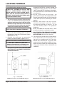
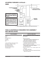
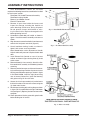
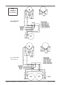
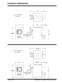
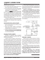
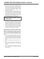
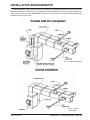
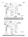
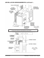
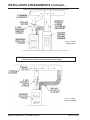
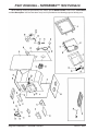
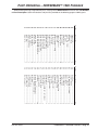
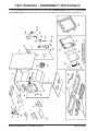
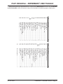
NORSEMAN™ Solid Fuel
Warm Air Furnace
Models 1500/2500 Owners Manual
(save this manual for future reference)
This furnace meets
U.S. Test Standard:
READ ALL INSTRUCTIONS CAREFULLY
BEFORE Installing OR OPERATING
This furnace.
Failure to follow instructions
may result in property damage,
bodily injury, or even death.
UL 391
NOTE: Installation MUST be
completed by a qualified
Heating Equipment Installer!
Do NOT use this Furnace in a
mobile home, Manufactured Home,
Tent or trailer – No Exceptions!
Vogelzang International Corporation
400 West 17th Street
Holland, Michigan 49423
www.vogelzang.com
Phone: 1-616-396-1911
Fax: 1-616-396-1971
VGZ-018 / 0805.1
NORSEMAN™ 1500/2500 Furnace / Page
SAFETY INSTRUCTIONS
Safety Notice: If this furnace is not properly installed, a house/building fire
may result. For your safety, contact local building or fire officials about
permits, restrictions, and installation requirements for your area.
Read All Instructions carefully.
Refer to instruction panels, caution and
warning plates on furnace for additional
information.
1. This fur nace is designed for INDOOR
installation only.
2. DO NOT attempt to retrofit this unit with any type
of water coil or water jacket.
3. The installation of this furnace must comply
with your local building code rulings. Please
observe the clearances to combustibles (see
reference figures 1–3). Do not place furniture
or other objects within the clearance area.
4. Verify that the furnace is properly installed before firing for the first time. Obtain the services
of a professional licensed installer familiar with
all aspects of safe and correct installation. DO
NOT use temporary or makeshift compromises
during installation.
5. DO NOT store wood, flammable liquids or other
combustible materials too close to the unit. Refer
to the certification label on back of unit and reference clearance instructions in this manual.
6. Do not install this furnace in a mobile home, manufactured home, tent
or trailer – NO EXCEPTIONS! (HUD Federal Standard: 24 CFR Ch.XX)
7. If any parts are missing or defective, please notify the manufacturer or dealer immediately. DO
NOT OPERATE A STOVE THAT IS MISSING
ANY PARTS
8. Always connect this furnace to a chimney and
vent to the outside. Never vent to another
room or inside a building. DO NOT CONNECT
THIS UNIT TO A CHIMNEY FLUE SERVING
ANOTHER APPLIANCE.
9. Do NOT connect this furnace to an aluminum
Type B gas vent. This is not safe. Use approved
masonry or a UL 103 HT Listed Residential
Type and Building Heating Appliance Chimney.
Use a 6” diameter chimney or larger, that is high
enough to provide required draft. (See specifics
in installation instructions).
10. Inspect flue pipes, pipe joints, and flue pipe
seals regularly to ensure that smoke and flue
gases are not drawn into, and circulated by the
air circulation system.
Page / NORSEMAN™ 1500/2500 Furnace
11.Cleaning of this furnace, is especially important at
the end of the heating season. Accumulated ash
attracts moisture and may cause corrosion during
the summer months.
12. B e s u r e t h a t y o u r c h i m n e y i s s a f e l y
constructed and in good repair. Have the chimney
inspected by the fire department or a qualified
inspector. Your insurance company may be able to
recommend a qualified inspector.
13.Creosote or soot may build up in the chimney
connector and/or chimney and cause a house,
building or chimney fire. Inspect the chimney
connector and chimney twice monthly during the
heating season and clean if necessary. (See Chimney Maintenance, page 18).
14. To prevent injury, do not allow anyone to use this
furnace who is unfamiliar with the correct operation
of the furnace.
15. Do not operate fur nace while under the
influence of drugs or alcohol.
16. Ashes should not be allowed to accumulate higher
than the ash pan. Dispose of ashes in a metal container with a tight fitting lid. Keep the closed container on a noncombustible floor or on the ground,
well away from all combustible materials. Keep the
ashes in the closed container until all cinders have
thoroughly cooled. The ashes may be buried in the
ground or picked up by a refuse collector.
17. Build several small fires on first use. This will help
to “season” the cast iron parts and avoid cracking.
Allow furnace to cool between firings.
18. The special paints used on your furnace may
give off some smoke and an odor while they
are curing during the first 12 to 15 fires.
Additional smoke and odor may be emitted from
the light oils used in construction of the fire box.
This should disappear after a short period of time
and not occur again. Persons with lung conditions
or owners of susceptible domestic pets (such as
birds) should take prudent precautions. Open windows and doors as needed to clear smoke and/or
odor. Paint discoloration will occur if the furnace
is over fired.
19. This furnace has a painted surface which is
durable but it will not stand rough handling or
continued on next page
VGZ-018 / 0805.1
SAFETY INSTRUCTIONS continued…
abuse. When installing your furnace, use care
in handling. Clean with soap and warm water
when furnace is not hot. Do not use any acids
or scouring soap, as these wear and dull
the finish.
20. While furnace is in operation, all persons, especially
young children, should be alerted to the hazards
from high surface temperatures and should be kept
away to avoid burns or clothing ignition.
21. If small children will be in the same room as the
furnace during operation, provide a sturdy barrier
to keep them at a safe distance from the stove.
NEVER LEAVE SMALL CHILDREN UNSUPERVISED when they are in the same room as the
stove.
22. Keep furnace area clear and free from all combustible materials, gasoline, and other flammable
vapors and liquids.
23. To prevent burns, always wear protective clothing,
leather hearth gloves and eye protection while
tending the fire.
24. While in operation, keep the feed door and ash door
closed at all times except while tending the fire.
25. Do not over fire the furnace. Over firing will happen
if the feed door or ash door is left open during operation. Such actions can result in very dangerous
operating conditions.
26. For fur ther information on using your furnace safely, obtain a copy of the National Fire
Protection Association (NFPA) publication, Using
Coal and Wood Stoves Safely, NFPA No. HS-101978. The address of the NFPA is Batterymarch
Park, Quincy, MA 02269.
NOTE: Installation should be completed by A professional, licensed
heating and cooling contractor Only.
VGZ-018 / 0805.1
NORSEMAN™ 1500/2500 Furnace / Page
Table of Contents
Safety Precautions...................................................................................... 2
Furnace Description & Installation Options..................................... 5
Locating the Furnace.................................................................................. 6
Tools and Materials Required for Installation............................. 7
Assembly Instructions................................................................................ 8
Furnace Installation................................................................................... 9
Wiring Diagram.............................................................................................. 10
Furnace Dimensions.................................................................................... 11
Chimney Connections................................................................................. 12
Connector Pipe Installation.................................................................. 13
Operating Instructions............................................................................ 15
Coal Burning Tips......................................................................................... 16
Blower Limit Control Settings............................................................. 17
Power Failure Instructions................................................................... 17
Blower Fan and Motor Care................................................................... 17
Chimney Maintenance................................................................................. 18
End of Season (Ash Removal) Maintenance...................................... 18
Installation Arrangement Diagrams.......................................... 19 – 22
Parts Norseman™ 1500....................................................................... 24 – 25
Parts Norseman™ 2500....................................................................... 26 – 27
Page / NORSEMAN™ 1500/2500 Furnace
VGZ-018 / 0805.1
Furnace Description & Installation Options
Your NORSEMAN™ Solid Fuel Warm Air Furnace
is designed to provide supplemental or central heating
for your home. This solid fuel furnace may be installed
in conjunction with a central furnace that is in proper
operating condition and meets all national and/or
local building codes, safety standards, required controls
and has been installed in accordance with appropriate
standards of the National Fire Protection Association
and in accordance with the clearances specified on the
furnace nameplate.
Installation of NORSEMAN™ Furnaces must
be accomplished by a qualified heating contractor
(one who is engaged in, and is responsible for, or is
thoroughly familiar with the installation and operation
of gas, oil, and solid fuel burning heating appliances,
who is experienced in such work and familiar with all
the requirements of the authority having jurisdiction.)
The installation shall be in strict accordance with the
manufacturer’s installation instructions furnished with
the solid fuel furnace.
The chimney connector of the furnace is to be installed to provide clearances to combustible materials
not less than specified in the individual classifications
and marked on the furnace. The chimney must be suitable for use with residential type or building heating
appliances which burn solid fuel.
The furnace is designed to operate in either parallel air flow arrangement with a central
furnace or as a stand alone central furnace. (See connection option diagrams, figures 17 – 23, on pages
19 – 22.)
NORSEMAN™ Warm Air Furnace, it is recommended
that it be fired as much as possible in order to reduce
the demand on the central heating system. An optional
forced draft kit (Model DK-50) is available that operates
from a wall thermostat. When the temperature falls
below the setting on the wall thermostat, the forced
draft will come on.
The warm air supply outlet of the
NORSEMAN™ Furnace must not be connected to the cold air return of the
central heating furnace because of the possibility of
overheating components of the central furnace and
causing it to operate other than it was designed.
Operating external static pressure and air temperature rise of existing furnace must be within ratings
marked on the central furnace nameplate. Test operation of central furnace after installation of supplementary
furnace.
Central Furnace Installation
As a central fur nace, the unit functions
independently of any other heating system. The
blower(s) will come on when the plenum temperature
reaches the setting on the blower control.
Parallel Installation
When the NORSEMAN™ War m Air Furnace is installed in parallel with an existing central heating furnace, it is designed to turn on the
central unit blower whenever the Warm Air Furnace blower turns on. The NORSEMAN™ blower
will only come on when the temperature in the
plenum has reached the setting on the blower
control. This insures there will be sufficient warm air
in the system to provide for efficient operation. When
the central system thermostat calls for heat, the central
system will operate by igniting the burner and turning
on the blower. It is possible that both systems will operate simultaneously. For the most efficient use of your
VGZ-018 / 0805.1
NORSEMAN™ 1500/2500 Furnace / Page
Locating Furnace
NOTICE: Installation of this furnace must be done
by a qualified heating equipment installer.
C A U T I O N : F urnace U nits are
heavy - approximately 450-550 lbs.
Make sure you have proper equipment and or sufficient manpower to
prevent injury when delivering and
locating furnace units.
1. The furnace must be placed on solid concrete or
masonry floor. NOTE: To reduce weight during installation remove parts from inside the firebox.
Additional weight reductions can be obtained
by removing the fire brick. Make note of position
so they are returned to the same positions.
CAUTION: Do not operate this appliance
with cracked or missing firebricks.
2. The furnace should be located in the same
room as the central heating system, as close as
possible but no closer than 6˝ to the central system.
(See figures 16 – 23)
3. Obser ve the clearances to combustible
materials as listed and shown in figures 1, 2 & 3.
Minimum Clearances to Combustible Surfaces
Front: 48 in. Side: 16 in. Back: 26 in.
Chimney Connectors: 18 in. Plenum to wallstuds, joists or finished wall or ceiling: 2 in.
5. Install furnace pipe, elbows, and thimble as
required, utilizing either a recently cleaned and
inspected 6˝ masonry chimney or a 6˝ i.d. listed UL
103 HT chimney. NOTE: A barometric draft regulator may be necessary if the chimney draft is found
to be excessive
6.U s e 6 ˝ r o u n d b l a c k f u r n a c e p i p e , n o t
galvanized furnace pipe. Secure pipe sections with
three (3) sheet metal screws in each furnace pipe
and/or elbow joint to firmly hold the pipe sections
together.
7. R e c h e ck c l e a r a n c e s f r o m t h e f u r n a c e ,
connector furnace pipe, and corner clearances using the illustrations in figures 1 – 3 and
your local building codes or fire protection
ordinances.
NOTE: A studded wall faced with brick or stone
should be considered a combustible surface.
8. Do Not install this furnace in a mobile
home, Manufactured home,tent or trailer.
NO EXCEPTIONS! (HUD Federal Standard: 24 CFR Ch.XX)
9. The clearances provided are minimum dimensions determined by the manufacturer’s testing facility in accordance with U.S. Test Standard UL 391. Installation of this furnace must
comply with the latest edition of NFPA 211 for reduced clearances and/or your local building code
rulings (use whichever minimum dimensions are
LARGEST).
4. The furnace must have its own flue. Do not connect this unit to a chimney flue serving
other appliances.
Fig. 1 – Top View
Minimum Clearances from Combustible Surfaces
Page / NORSEMAN™ 1500/2500 Furnace
Fig. 2 – SIDE View
Minimum Clearances from Combustible Surfaces
VGZ-018 / 0805.1
Locating Furnace continued…
CAUTION: Keep furnishings
and other combustible
materials away FROM the
furnace.
N O T E : B efore firin g
furnace, slide firebricks
towards rear so no gaps
remain between bricks. Do
not operate Furnace with
cracked or missing Fire
bricks.
Fig. 3 – Minimum Plenum Clearances from Combustible Materials
Tools & Materials required for Assembly
and Installation
tools required
Safety Glasses
Gloves
Pencil
6 ft. Tape Measure
Tin Snips
Sabre Saw
Drill
1/8” dia. Drill Bit (for sheet metal screws)
Screwdrivers (Phillips & slotted)
6mm Socket with Driver
10mm Socket with Driver
10mm open end box wrench
7/16” box wrench
VGZ-018 / 0805.1
materials required
NOTE: The following items are NOT included with
your furnace.
Chimney Connection:
6” black steel (24 ga. min.) straight furnace pipe,
elbow, Collar and Thimble (as required).
6˝ Barometric Draft Regulator (optional)
8˝ Round Butterfly Anti-Backdraft Damper
(2 required – for parallel installation only)
Plenum & Duct Work (as required).
Chimney: Existing 6” Lined Masonry Chimney
or 6” Inside Dia. Listed Type HT chimney.
1/2” Sheet Metal Screws
E l e c t r i c a l W i r i n g : 1 8 g a . AW G c o p p e r w i t h
90° C min.
1/2˝ Conduit & Connectors
Furnace Cement (manufacturer recommends Rutland
Code 78 or equivalent)
NORSEMAN™ 1500/2500 Furnace / Page
Assembly Instructions
Yo u r N O R S E M A N ™ Wa r m A i r F u r n a c e
requires the following items to be assembled or installed
by the furnace installer:
Feed Door Pull Handle/Thermostat Assembly
Feed Door Locking Handle
Blower(s) and Blower Control
Electrical Connections
1. Remove all parts from inside the furnace and
inspect for damage, including the firebrick as
some breakage could occur during shipment.
Do not operate furnace with broken or missing fire box bricks. Replace damaged bricks
before operating furnace.
2. Assemble the feed door pull handle as shown in
figure 4. Install thermostat assembly and cover as
shown.
3. Align thermostat control knob with flat on thermostat
control shaft and press onto shaft (figure 4).
4. Attach feed door locking handle as shown in
figure 5 with screws and nuts provided.
Note: Slotted holes are for adjustment of handle.
Adjust handle until pressure is required to lock feed
door.
5. Install Blower/Limit Control on rear of furnace
cabinet as shown in figure 6 using three (3) sheet
metal screws.
6. Remove blower(s) from carton(s). Attach the flexible conduit/wire assembly to the blower(s) before
mounting.
7. Remove junction box cover and take out the mounting hardware package. Position clip nuts to furnace
housing around blower opening as shown in figure
6. On Model #2500, install the right (when facing
rear of furnace) blower first. Install the blower(s)
with gasket using 1/4-20 x 3/4˝ bolts.
8. Secure the 4 inch square electrical junction box to
the black bracket on the rear of the stove using two
(2) sheet metal screws.
9. Wire blower according to the wiring diagram shown
in figure 7/8. On model 2500, wire right side blower
first (see figure 7). Replace junction box cover when
complete.
10.Check operation of shaker grates with grate handle
before loading fuel in furnace.
Fig. 4 – Door/Handle/Thermostat Assembly
Fig. 5 – Feed Door Handle Assembly
Fig. 6 – Blower Assembly
Page / NORSEMAN™ 1500/2500 Furnace
VGZ-018 / 0805.1
Furnace Installation
NOTE: Installation must be made by a qualified
heating equipment installer (one who is engaged in,
and is responsible for, or is thoroughly familiar with the
installation and operation of gas, oil, and solid fuel burning heating appliances, who is experienced in such work
and familiar with all the building requirements and/or fire
codes of the authority having local jurisdiction.)
This is a furnace, not a stove. Heated air must be
directed away from the furnace or it will not operate
properly.
1. T h e i n s t a l l a t i o n i s t o b e c o m p l e t e d i n
accordance with National Fire Protection
Association (NFPA) installation standards No.
89M, 90B, 211, 70 (National Electrical Code) and
Uniform Mechanical Code 913, 6-4 in states where
applicable (where code offers making flue pipe
connections into an existing chimney with other
fuel burning appliances).
2. Wood/coal burning appliances need air for
combustion and circulation to the house.
Provision must be made to provide make up
air so as not to starve the central heating
system of combustion air. Have the local regulating authority determine that make up air
supply is adequate. Reference NFPA standards
No. 30 & 54, Code for Installation of Gas and Oil
Equipment.
3. H ave t h e l o c a l r e g u l a t i n g a u t h o r i t y o r
qualified exper t inspect all chimneys and
installations for adequate venting and for
compliance with standard local codes and
regulations regarding installation of wood/coal
burning appliances. (Also see Pipe Installation on
following pages.)
4. Position the fur nace according to clearances shown in figures 1–3 and to maintain
chimney connections as short as possible. Avoid
unnecessary turns and installation of devices that
would create excessive resistance to the flow of
flue gases.
5. Make flue pipe connections to the chimney
with 24-gauge pipe and elbows (not included
with furnace) maintaining proper clearances.
Seal the flue pipe in the chimney with furnace cement. (Chimney connections must be
securely supported and joints fastened with sheet
metal screws.)
VGZ-018 / 0805.1
6. For parallel installations, install (two) 8˝ anti-backdraft butterfly dampers (Vogelzang Model AD-8, not
included with the furnace) in the heat (duct) pipes
a minimum of 18 inches above the furnace
plenum. Anti-backdraft butterfly dampers may be
obtained where you purchased your appliance or
from a local HVAC distributor.
7. Install 8˝ diameter 26-gauge heat (duct) pipe
and connectors (not included with furnace) to
make connection to the plenum of the central
heating system. The heat pipe, plenum, and
connections must be constructed of metal with
a minimum temperature rating of 250° F. If
central air conditioning is installed in the
p l e nu m , i n s t a l l h e a t p i p e a b ove t h e a i r
conditioning unit. Secure the heat pipe
connection with suppor ts and sheet metal
screws.
8. Make electrical supply connections in the
electrical junction box and connect power
supply wires to designated wires using wire nuts
(see wiring diagram figure 7 & 8). The power cord
supplied may be used for installation if local codes
and regulations permit. If not permitted, power
supply wiring must be minimum of 18-ga. AWG
copper and rated for 90° Centigrade installed in a
metal cable or conduit. Power connections should
be made by a qualified installer to comply with
NFPA Standard No. 70 and all local codes and
regulations.
NORSEMAN™ 1500/2500 Furnace / Page
NOTE:
Do NOT break
off jumper
for low voltage.
Fig. 7 – Model 1500
Wiring Diagram
Fig. 8 – Model 2500
Wiring Diagram
Page 10 / NORSEMAN™ 1500/2500 Furnace
VGZ-018 / 0805.1
Furnace Dimensions
Fig. 9 – Model 1500
Dimension
Fig. 10 – Model 2500
Dimensions
VGZ-018 / 0805.1
NORSEMAN™ 1500/2500 Furnace / Page
11
Chimney connections
DRAFT
Chimneys perform two functions.
1). As a means of exhausting smoke and flue gases
which are the result of fuel combustion.
2). The chimney provides “draft” which allows oxygen
to be continuously introduced into the appliance,
so that proper combustion is possible.
NOTE: The furnace does not create draft.
Draft is a function of the chimney. A minimum of 0.05
w.c.,( measured in water column) is required for proper
drafting to prevent back-puffing, smoke spillage, and to
maximize performance. (Gauges to measure chimney
draft are readily available at furnace shops and are
economical to purchase or rent.)
As of April 1, 1987 all coal stoves must be installed
using a factory built chimney that meets the “Type HT”
requirement of UL 103 (when using a factory built
chimney).
When using a pre-existing chimney, have it’s condition and installation inspected before using. Make sure
that the chimney meets all of the UL rating requirements
listed above. Be aware that not all manufactured chimney is of the UL 103 HT type.
NOTE: It is recommended that you contact a
licensed heating and cooling contractor (consult
your local yellow pages) for chimney installation.
Manufactured chimney with the proper required UL
listing is available from most home centers, hardware
stores, and HVAC supply stores.
If you have access to the internet, you may wish
to view chimney manufacturers’ information on-line.
See, www.duravent.com, www.selkirkinc.com, or
www.mtlfab.com.
Important Installation Points
1. Size the chimney flue to the furnace pipe. (6” outlet
pipe = 6” chimney flue)
2. Avoid using elbows except as necessar y.
Elbows reduce draft, no more than two elbows
should be used in any chimney run.
3. Make sure all horizontal runs of connector pipe have
a minimum outward rise of 1/4” per horizontal foot.
This allows any condensation or creosote buildup
to run back into the firebox.
Manufactured Chimney
R efer to c himney and c himney
connector maker’s instructions for
installation and use.
Carefully follow chimney manufacturer’s
instructions. Use only a listed chimney. If your chimney
starts at the ceiling (figures 13 & 14) you will need
enough 6” round black connector pipe to reach the ceiling. The top of the chimney must be at least three (3)
feet above the roof and be at least two (2) feet higher
than any point of the roof within ten (10) feet (figure 13).
Use only 6” diameter listed chimney UL 103 HT. Chimney made to this listing is High Temperature rated to
2100 degrees Fahrenheit. Use chimney from only one
manufacturer. Never mix brands. Carefully follow the
chimney manufacturer’s stated requirements and clearances. Use the chimney manufacturer’s attic guards,
roof supports, flashing and fire stops when passing
through a ceiling. Use a listed thimble when passing
through a combustible wall. Do not use makeshift compromises during installation. Never use a singlewall connection pipe as a chimney!
Page 12 / NORSEMAN™ 1500/2500 Furnace
Fig. 11 - Masonry Chimney Connection
Masonry Chimney
Before using an existing masonry chimney,
clean the chimney, inspect the flue liner and make
any repairs needed to be sure it is safe to use. Make
repairs before attaching the furnace. The connector furnace pipe and fittings you will need to connect directly to a masonry chimney are shown in
figure 11 and 12.
If the connector furnace pipe must go through a
combustible wall before entering the masonry chimney,
consult a qualified mason or chimney dealer. The installation must conform to local building and fire codes and
latest edition of NFPA 211.
D o not connect t h is furnace
into the sam e chim ney flue as t he
fireplace, gas appliance, or a flue
connected with any other furnace.
continued on next page
VGZ-018 / 0805.1
Chimney connections continued …
The chimney used for a furnace must not be used to
ventilate the cellar or basement. If there is a clean out
in the base of the chimney, close it tightly.
ThImBLE
6˝ ROUND
24 ga. BLACk
CONNECTOR
STOvEPIPE
COLLAR
ChImNEY
FLUE
5/8" TILE
ChImNEY
LINER
8˝ mIN.
LINER
BELOw
ENTRY
hOLE
mASONRY
ChImNEY
Fig. 12 - Masonry Chimney Connection
If you have any questions regarding venting your
furnace, contact the manufacturer or contact the National Fire Protection Association (NFPA) and request
a copy of the latest editions of NFPA Standard 211
and NFPA Standard 908. Their address is:
Battery March Park, Quincy, MA 02269.
Fig. 13 - Chimney Construction
Through Roof
Connector Pipe Installation
NOTE: Connector pipe is NOT INCLUDED.
To purchase, Visit your local hardware, home or building center. See
“Locating Furnace” page 6 for additional specifications.
1. The crimped end of the connector pipe fits inside
the furnace flue collar. Install additional pipe and
elbow with the crimped end towards the furnace.
This will allow any condensation in the flue to run
back into the firebox.
2. Horizontal pipe runs must slope upwards
towards the chimney at least 1/4˝ per foot of horizontal run.
3. You must have at least 18 inches of clearance
between any horizontal piping and the ceiling.
4.Connector pipe cannot extend into the chimney flue
(figure 14).
5. Secure pipe/elbow sections with three (3) sheet
metal screws at each joint to make the piping
rigid.
continued on next page
CORRECTWRONGWRONG
Fig. 14 – Stovepipe/Flue Connections
VGZ-018 / 0805.1
NORSEMAN™ 1500/2500 Furnace / Page
13
Connector Pipe Installation continued…
6. It is recommended that no more than two (2)
90° bends be used in the connector pipe installation. The use of more than two 90° bends
may decrease the amount of draft and possibly
cause smoke spillage. Where possible, use only
corrugated (nonadjustable) elbows. These
are much more airtight.
7. The connector pipe must not pass through an attic
or roof space, closet, any concealed space, floor,
ceiling, wall or combustible construction. (See
Chimney Connections, page 10). A UL 103 HT
Listed chimney must be used from the first penetration of ceiling or wall to the chimney cap.
C AU T I O N : N e v er use sin g le wall
connector pipe as a chimney – a house
fire could result.
8. The chimney connector may include a section for
a barometric draft regulator between the furnace
and the chimney (figures 2, 11 & 13). The optional
barometric draft regulator must be installed in the
same room (same pressure zone) as the furnace.
9. Install the optional barometric draft regulator
strictly in accordance with the instructions that are
provided with the barometric draft regulator.
Barometric Draft Regulator Setting
Note: This optional device is NOT included with
the furnace. A Barometric Draft Regulator (Vogelzang Model BD-06) is used to overcome excessive
draft.
1. Drill a hole in the chimney connector within 18˝ of
the flue collar below the barometric draft regulator
just large enough for the tube of the manometer.
2. Build a fire after all chimney connections have been
made.
3.Use the manometer to measure the draft in the
flue.
4. Adjust the Barometric Draft Regulator to
obtain a draft of 0.05˝-0.06˝ W.C. under stable fire
conditions.
5. After all adjustments have been made, seal
the hole made for the manometer tube with
furnace cement.
Page 14 / NORSEMAN™ 1500/2500 Furnace
VGZ-018 / 0805.1
Operating Instructions
CAUTION: HOUSE FIRE HAZARDS
•Gases emitted from freshly added
coal must be burned or they will
accumulate and Explode. Never smother a fire when adding fresh coal.
• N e v er use m anufactured coal
“bricks” made of coal dust and waxtype binder.
• Over firing may cause a house fire.
If a unit or chimney connector glows,
you are over firing.
• Build fires only on integral grate
included with the furnace.
Operating Safety Precautions
1. Never over fire this furnace by
building excessively hot fires as
a house/building fire may result.
2. Do not operate with feed or ash
doors open. Over firing may result.
3. Never build extremely large fires
in this type of furnace as damage to
the furnace or smoke leakage may
result.
4. H OT w h ile in operation . Keep
children, clothing, and furniture away.
Contact may cause skin burns. Do not
touch the furnace after firing until
it has cooled.
5. Provide air into the room for
proper combustion.
WARNING: Explosion Hazard
• Never use chemicals, gasoline, gasoline-type lantern fuel, kerosene,
charcoal lighter fluid, or similar
flammable liquids to start or “freshen-up” a fire in the furnace.
•Keep all flammable liquids, especially gasoline, out of the vicinity of
the Furnace — whether in use or in
storage.
• Inspect and clean flue pipe every 90
days. Replace immediately if flue pipe
is rusting or leaking smoke into the
room.
• Do not operate furnace with a draft
exceeding 0.06˝ w.c. (water column).
VGZ-018 / 0805.1
Fuel(s)
This furnace is designed to burn wood or
coal fuel.
Coal Fuel
Low ash content (2% to 6%) coal is recommended.
Purchase “washed” coal in chestnut, egg, furnace, or
nut-sizes (1-3/4 to 4 inch diameter) for residential furnaces. Any of the specialty packaged fireplace coals can
also be used. (Do not use wax-type coal “bricks”)
NOTICE: For best results use solid,
Bituminous coal. NEVER use manufactured coal “bricks” made of coal dust
with wax-type binder. Do Not burn
garbage or flammable fluids. Store
coal in dry, well ventilated area.
Wood Fuel
Hardwood, 18˝ to 26˝ should be split and air dried
(seasoned) for 6 months to provide proper burning
without excessive creosote buildup.
Lighting
NOTE: On first use build three (3) small fires
to “season” cast iron parts and prevent cracking.
Allow furnace to cool between firings.
1. Set the thermostat on “HIGH” to provide maximum
draft.
2. Open the feed door and place paper and kindling
on the grate for starting the fire.
3. Light fire, close and secure the feed door.
4. Add wood or about 15 pounds of coal after fire
is burning briskly. Use care not to smother the
kindling fire when adding coal.
5. Set the thermostat to maintain desired temp e ra t u r e. “ M E D I U M ” s e t t i n g i s n o r m a l l y
satisfactor y. Set higher or lower for your
personal comfort level.
Adding Fuel
When starting fires, add small amounts of fuel
each hour or so instead of piling large quantities
of fuel every 3 to 5 hours. As you become more
familiar with the operation of your furnace, it is
possible to add fuel to burn for longer periods of time, but
doing so carelessly will promote incomplete combustion and considerable sooting, along with a very dirty,
inefficient fire.
continued on next page
NORSEMAN™ 1500/2500 Furnace / Page
15
Operating Instructions continued …
1. Set thermostat to “HIGH” before opening the feed
door.
2. Never smother the fire when adding fuel (especially
coal.) Incomplete combustion of fresh coal will
cause gas accumulation and a mild smoky explosion, known as back puffing, will occur:
– Add fresh kindling if the bed of coals has
cooled.
– Add up to 20 lbs. of coal or wood to a convenient
level. Never add fuel above the top of the firebrick.
– Stir the coals and watch the fire. Be sure new coal
is burning before you close the doors and turn the
thermostat down.
3. At least once every 12 hours of operation crank
the roller grate system to dump ‘clinkers’ and ash
into the ash pan. A couple of gentle “cranks”, is all
that is required. Stop cranking when you observe
a few red coals falling into the ash pan. Excessive
cranking can expose the grates to very high heat
and warp or damage the grates.
4. Empty ash pan regularly. Do not allow ashes
to pile up to the grate. If ashes build up to
the grate, it can warp and burnout will occur.
If allowed to overfill, ashes may spill when
removing the pan.
5. Properly dispose of hot ashes (see Safety
Instructions, item #17 on page 3).
Coal Burning Tips
The size of coal fuel is critical - too large and it won’t
burn well, too small and it will smother the fire creating
excessive smoke and gases. Purchase Bituminous coal
“nuggets” that are 1-3/4” to 4” diameter and that have
been “cleaned” to remove rocks and other minerals.
Bituminous coal is recommended for ease of use
but produces a greater amount of volatile gases so it is
important to build and refresh coal fires properly. Extra
maintenance will also be required to remove accumulated soot on heating surfaces and pipes.
All fires should be initially started using wood kindling. Hardwood is best as it creates a hotter bed of
coals that is necessary to ignite the coal.
Once a hot bed of wood coals has been established
an initial layer of coal may be placed in the firebox. Due
to the high amount of volatile gas produced by coal, the
initial flames will be long and of an orange or yellow
color accompanied by quite a bit of smoke. As the gas
is burned off the flames will become shorter, the color
will change and less smoke will be produced.
Once the fire is well established, add coal to the
Page 16 / NORSEMAN™ 1500/2500 Furnace
center of the firebox in a conical arrangement. The highest part of the fuel should be in the center of the fire box.
This allows the heat to drive off the volatile gases and
the turbulence created causes a more efficient burn.
Remember to allow enough secondary air to enter
the fire box and keep the stove pipe damper open to
properly burn off the volatile gases. You will have to
experiment with your particular setup (fire construction, fuel load, spin draft control, damper and automatic
settings) as no two arrangements of furnace/chimney
are the same.
When refueling a coal fire, use a poker to break
up any crust that may have formed being careful not to
mix the coal which may increase the chance of forming
“clinkers.”
Banking a coal Fire
A fire should be banked for extended operation
without tending, such as overnight. This is accomplished by heaping the fuel along the sides and back
of the fire box so that the fire gradually burns through
the fuel. This reduces the intensity of the fire without
letting it go out.
Use the same procedures as in refueling but without shaking the grates. The layer of ash will help to
reduce the intensity of the fire. After loading the fuel
in this manner, let the fire establish itself for about 30
minutes then close the damper and adjust the automatic control to a point so that the house does not get
too cold. Make sure you leave yourself enough time to
bank the fire before leaving or retiring so you can make
the necessary adjustments after the fire has become
well established.
Reviving a fire
To revive a fire that has almost gone out, increase
the draft through the grates by opening the ash door
and stove pipe damper and closing the door spin draft
control(s). Place a thin layer of new coal over the entire
fire but DO NOT SHAKE the fire grates. Doing so may
cause the live coals to drop through the grates. Once
the fresh layer of coal has ignited you may shake the
grates (slightly) and refuel as usual.
CAUTION: Do not smother a fire when
adding coal. Gases driven off from
fresh coal must be burned or they may
accumulate and explode. Whenever refueling, open the pipe damper and turn
the thermostat damper to high before
opening the door to allow any accumulated gases to be burned off.
VGZ-018 / 0805.1
Blower Limit Control Settings
The temperature in the plenum of the warm air furnace at which the blower turns on or off, is controlled by
the blower limit control settings. Indicators (see figures
7 & 8, page 10) in the control may be adjusted through
their entire range of settings to achieve the desired
warm air output (see figure 15).
Move both pointers towards the right (counter
clockwise) – this increases the temperature setting at
which the blower will turn on and off. Move both pointers
towards the left (clockwise) – this decreases the on/off
temperature setting. Increasing the distance between
the pointers increases the time the blower will run on
each warm air cycle.
Fig. 15 – Blower Limit Control Settings
Power Failure Instructions
Operation during power loss:
Do not expect to keep home at normal temperatures.
1. Remove air filter if provided.
2. Reduce fire to a low burn.
3. Set bimetal thermostat on LOW setting and set spin
draft on ash door to a minimum of one turn open.
4. Do not load fuel above bottom of feed door.
Blower Fan and motor Care
Oil blower motor(s) twice a year. Add five drops of
light weight (SAE 20) oil to each oiler tube. If the blower
and fan accumulate moderate to heavy dust, vacuum,
wipe and/or blow dust from motor housing and fan.
VGZ-018 / 0805.1
NORSEMAN™ 1500/2500 Furnace / Page
17
Chimney Maintenance
CHIMNEY DRAFT
CREOSOTE – Formation and Removal
Do not expect the furnace to draw. Draft is a function of the chimney, not the furnace. Smoke spillage
into the house or excessive buildup of condensation
or soot in the chimney are warnings that the chimney
is not functioning properly. Correct the problem before
using the furnace. Following are some possible causes
for improper draft.
1. The connector stovepipe may be pushed into the
chimney too far, stopping the draft (figure 14, page
13).
2. If the chimney is operating too cool, water will
condense in the chimney and run back into the
furnace. Soot formation will be rapid and may block
the chimney. Operate the furnace at a high enough
fire level to keep the chimney warm preventing this
condensation.
3. If the fire burns well but sometimes smokes or burns
slowly, it may be caused by the chimney top being
lower than another part of the house or a nearby
tree. The wind blowing over a house or tree falls on
top of the chimney like water over a dam, beating
down the smoke. The top of the chimney should be
at least three (3) feet above the roof and be at least
two (2) feet higher than any point of the roof within
ten (10) feet.
When wood or coal is bur ned slowly, it
produces tar and other organic vapors which
combine with expelled moisture to form creosote. The
creosote vapors condense in the relatively cool chimney
flue of a slow-burning fire. As a result, creosote residue
accumulates on the flue lining. If ignited, this creosote
creates an extremely hot fire which may ignite surrounding materials resulting in a building fire.
The chimney connector and chimney should be inspected at least twice a month during the heating season to determine if a creosote buildup has occurred.
If creosote has accumulated, it should be removed. Failure to remove creosote may result
in ignition and may cause a house/building fire.
Creosote may be removed using a chimney brush
or other commonly available materials from your
local hardware retailer.
Chimney fires burn very hot. If the chimney connector should glow red, immediately call the fire department, then reduce the fire by closing the inlet air control
and pour a large quantity of coarse salt, baking soda,
or cool ashes on top of the fire in the firebox.
NOTE: A draft reading of 0.05 w.c.
(water column) is suggested for proper burning of this furnace.
CAUTION: A chimney fire may cause ignition of wall studs or rafters which
were assumed to be a safe distance
from the chimney. If a chimney fire
has occurred, have your chimney
inspected by a qualified person
before using again.
End of Season Maintenance
Remove all accumulated ash from inside fire box and
ash drawer compartment. Ash will absorb moisture and
can cause corrosion.
Page 18 / NORSEMAN™ 1500/2500 Furnace
VGZ-018 / 0805.1
Installation Arrangements
Your NORSEMAN™ Warm Air Furnace can be installed as a supplemental add-on unit (figure 16) or as a
central heating system (figure 17). The following illustrations depict the various installation configurations
which may be used to install your NORSEMAN™ Warm Air Furnace. Always have a qualified heating equipment
professional install your furnace.
Fig. 16 – Add-on Installation
Fig. 17 – Central
Installation
VGZ-018 / 0805.1
NORSEMAN™ 1500/2500 Furnace / Page
19
Fig. 18 – Add-on Heat Pipe
Installation
NOTE: To prevent damage from overheating, Backdraft Dampers must be installed
no closer than 18 inches to the top surface of the furnace.
Fig. 19 – Add-on Plenum
Collector Box
Page 20 / NORSEMAN™ 1500/2500 Furnace
VGZ-018 / 0805.1
Installation Arrangements continued …
Fig. 20 – Add-on
Optional Plenum
Collector
NOTE: To prevent damage from overheating, Backdraft Dampers must be installed
no closer than 18 inches to the top surface of the furnace.
Fig. 21 – Add-on
Plenum Backdraft
Flapper
VGZ-018 / 0805.1
NORSEMAN™ 1500/2500 Furnace / Page
21
Installation Arrangements continued …
Fig. 22 – Add-on
Angled Plenum
NOTE: To prevent damage from overheating, Backdraft Dampers must be installed
no closer than 18 inches to the top surface of the furnace.
Fig. 23 – Central
Furnace Installation
Page 22 / NORSEMAN™ 1500/2500 Furnace
VGZ-018 / 0805.1
VGZ-018 / 0805.1
NORSEMAN™ 1500/2500 Furnace / Page
23
Part Ordering – NORSEMAN™ 1500 furnace
When ordering missing or replacement parts, always give the Model Number of the furnace, Part Number,
and Part Description. Use the illustrations and part lists provided on the following pages to identify parts.
Page 24 / NORSEMAN™ 1500/2500 Furnace
VGZ-018 / 0805.1
Part Ordering – NORSEMAN™ 1500 furnace
When ordering missing or replacement parts, always give the Model Number of the furnace, Part Number,
and Part Description. Use the illustrations and part lists provided on the following pages to identify parts.
DescriptionQty.
01Cabinet, LH................................................ 1
02Cabinet, Back............................................. 1
03
Draft Ring................................................... 1
04
Gasket, Flue Collar.................................... 1
05
Flue Collar.................................................. 1
06
Ring, Flue Collar........................................ 1
07
Bolt, 1/4-20x1˝............................................ 6
08
Keep Nut, 1/4-20........................................ 6
09Cabinet, Top Panel..................................... 1
10Cabinet, RH............................................... 1
11
Bracket, Feed Door Hinge.......................... 1
12
Smoke Curtain........................................... 1
13
Bolt, 5/16-18x1........................................... 2
14
Locknut, 5/16-18........................................ 2
15
Ash Door Assembly................................... 1
16
Feed Door Assembly.................................. 1
17
Thermostat Cover Asm.............................. 1
18
Thermostat Assembly................................ 1
19
Thermostat Control Knob........................... 1
20
Thermostat Damper Chain........................ 1
21
Thermostat Damper Flap Asm. ................. 1
22
Handle, Wood............................................ 1
23
Bracket, Handle.......................................... 2
24
Screw, 10-24x1/2˝...................................... 2
25
Handle, Ash Door....................................... 1
26
Washer, 3/32˝ Thick .................................. 1
27
Latch, Door................................................ 1
28
Nut, 3/8-16................................................. 1
Part No.
DescriptionQty.
29
Ash Pan..................................................... 1
30Cabinet, Bottom......................................... 1
31
Lock Mechanism, Feed Door .................... 1
32
Bolt, 1/4-20x3/4˝......................................... 2
33
Blower Motor.............................................. 1
34
Bolt, 1/4-20x3/4˝......................................... 5
35Clip Nut, 1/4-20 ......................................... 5
36
Gasket, Blower........................................... 1
37
Fan Control Conduit Asm........................... 1
38
Blower Conduit Asm................................... 1
39
Strain Relief............................................... 1
40
Blower Limit Control................................... 1
41
Junction Box............................................... 1
42Cord, Power Supply................................... 1
43
Baffle, Flue................................................. 1
44
Shaker Grate.............................................. 1
45
Shaker Frame (weldment - not shown)
46
Shaker Handle........................................... 1
47
Liner, Front & Rear..................................... 1
48
Firebox Assembly....................................... 1
49
Firebrick.................................................... 10
50
Bracket, Blower Thermostat....................... 1
51
Bracket, Relay Box Support....................... 1
52
Draft Knob.................................................. 1
53Clip, Smoke Door....................................... 2
54
Keep Nut, 1/4-20........................................ 2
55
Bolt, 1/4-20x1-1/4˝..................................... 2
56
Motor Capacitor......................................... 1
Part No.
25
NORSEMAN™ 1500/2500 Furnace / Page
VGZ-018 / 0805.1
Part Ordering – NORSEMAN™ 2500 furnace
When ordering missing or replacement parts, always give the Model Number of the furnace, Part Number,
and Part Description. Use the illustrations and part lists provided on the following pages to identify parts.
Page 26 / NORSEMAN™ 1500/2500 Furnace
VGZ-018 / 0805.1
Part Ordering – NORSEMAN™ 2500 furnace
When ordering missing or replacement parts, always give the Model Number of the furnace, Part Number,
and Part Description. Use the illustrations and part lists provided on the following pages to identify parts.
DescriptionQty.
01
Firebox Weldment...................................... 1
02Cabinet Bottom.......................................... 1
03Cabinet Side (LH & RH)............................. 2
04Cabinet Back.............................................. 1
05Cabinet Top................................................ 1
06
Liner, Front/Back........................................ 1
07
Liner, Front................................................. 1
08
Firebrick................................................... 12
09
Smoke Curtain........................................... 1
10
Keep Nut, 1/4-20........................................ 2
11Clip, Smoke Curtain................................... 2
12a
Bolt, 1/4-20x1-1/4˝..................................... 2
12b
Lockwasher, 1/4˝ i.d................................... 2
13
Ash Door Assembly................................... 1
13a
Door, Ash................................................... 1
13b
Gasket, Ash Door....................................... 1
14
Draft Knob.................................................. 1
15
Handle, Ash Door....................................... 1
17
Latch, Door................................................ 1
18
Jamb Nut, 3/8-16....................................... 2
19
Ash Pan Weldment..................................... 1
20
Bracket, Feed Door Hinge.......................... 1
21
Feed Door Handle Assembly..................... 1
22
Gasket, Flue Collar.................................... 1
23Collar, Flue................................................. 1
Part No.
DescriptionQty.
Motor Capacitor......................................... 1
24
Bracket, Blower Thermostat....................... 1
25
Limit Control . ............................................ 1
26
Flue Collar Ring......................................... 1
27
Forced Draft Ring....................................... 1
28
Bracket, Relay Box..................................... 1
29
Junction Box............................................... 1
30
Feed Door Assembly.................................. 1
30a
Door, Feed................................................. 1
30b
Gasket, Feed.............................................. 1
32
Knob, Thermostat Control.......................... 1
31
Thermostat Panel Assembly...................... 1
33Cover Weldment, Thermo. Panel................ 1
34
Panel Assembly, Thermostat...................... 1
35Chain Link ....................................... 0.542 ft
36
Bracket, Handle.......................................... 2
37
Handle, Round Wooden............................. 1
38
Handle, Shaker.......................................... 1
39
Frame, Shaker........................................... 2
40
Grate, Shaker............................................. 2
41
Blower Assembly....................................... 2
42
Gasket, Blower........................................... 2
43Conduit Assembly, Fan Control.................. 1
44Conduit Assembly, Blower......................... 2
45Clip Nut, 1/4-20........................................ 10
46
Baffle, Flue................................................. 2
Part No.
56
27
NORSEMAN™ 1500/2500 Furnace / Page
VGZ-018 / 0805.1
This Vogelzang heating appliance is safe when installed properly and will provide you with years of service.
However, always exercise good judgement when you are using this furnace. You are dealing with FIRE! Fire is
inherently dangerous and must be treated with respect. Stay warm and in good health!
Respectfully yours,
Steve Vogelzang
Proprietor
Company Testimony:
“For God so loved the world that he gave his only begotten Son, that whoever
believes in Him shall not perish but have eternal life”
John 3:16
MADE IN CHINA
Vogelzang International Corporation
400 West 17th Street
Holland, Michigan 49423
www.vogelzang.com
Phone: 1-616-396-1911
Page 28 / NORSEMAN™ 1500/2500 Furnace
VGZ-018 / 0805.1