1
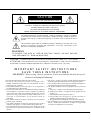
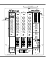
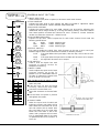
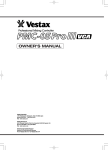
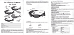
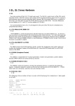
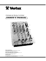
Professional Mixing Controller
OWNER'S MANUAL
VESTAX CORPORATION
2
3
7
1K
a
m
i
u
m
a
,S
e
t
a
g
a
y
a
k
u
,T
o
k
y
o1
5
4
0
0
1
1J
a
p
a
n
P
h
o
n
e
:
0
3
3
4
1
2
7
0
1
1F
a
x
:
0
3
3
4
1
2
7
0
1
3
VESTAX MUSICAL ELECTRONICS CORPORATION
4
2
4
0
CS
o
u
t
hM
o
b
i
l
eC
i
r
c
l
e
.A
u
r
o
r
a
.C
o
l
o
r
a
d
o8
0
0
1
5U
.
S
.
A
.
P
h
o
n
e
:
3
0
3
7
6
6
5
2
6
9F
a
x
:
3
0
3
7
6
6
2
1
9
6
E
m
a
i
l
:
v
e
s
t
a
x
c
o
r
p
o
r
a
t
i
o
n@
m
s
n
.c
o
m
VESTAX (Europe)Ltd.
1
8s
t
.
C
h
r
i
s
t
o
p
h
e
r
sR
o
a
d
,H
a
s
l
e
m
e
r
e
,
S
u
r
r
e
yG
U2
71
D
QE
n
g
l
a
n
d
.
P
h
o
n
e
:
(
0
)
1
4
2
8
6
5
3
1
1
7F
a
x
:
(
0
)
1
4
2
8
6
6
1
0
2
1
CONGRATULATIONS!
Thank you for purchasing the VESTAX PMC -27MKII,Professional Mixing Controller.As
The top of the line, the PMC-27MKII is a high specification mixer designed to meet the most
professional requirements of the Dance Music DJ's.
Please read this owner's manual carefully before you start to use your mixer, so that you will
fully understand all of the special features and enjoy the full of use of the product.
IMPORTANT
PRECAUTIONS
To prevent electric shock, do not remove the cover. No user
serviceable parts are inside. Please refer servicing to a
VESTAX Authorized Service Center. Always disconnect all
equipment from the main supply when disconnecting or
reconnecting signal leads. The power cord should be
connected last. Make sure that the power switch is off when
connecting the power cord. Disconnect from AC supply when
equipment is not used for exlended amount of time.
*Humidity and dust
Avoid use where there is high humidity and dust which may
cause damage to internal parts.
*Temperature
Avoid use in hot, (over 35℃)and cold, (boiow 5℃)
locations. Keep the unit away from extreme direct heat such
as direct sunlight, heating radaitors, or closed vehictes.
*Power cord handling
Connecting the power cord to other cords or joining cords
together can cause lire and electric shock. This is extremely
dangerous.
Take precaution when handling ACplugs and connectors.
Handle only the plug or connector and do not perfrom these
operations wiht wet hands.
*Keep away from liquids
Do not stand cans contaning lipuids on or near the
equipment. If liquid enters equipment, disconnect the power
cord from the power outlet immediatcly.
WARRANTY
The warranty might vary from country to country. Each
distributor has their own warranty system in accordance with
the country or state regulations or laws. VESTAX observes the
manufacturing coubtry’
s regulations.
F E AT U R E S
Three band isolator switch kills each frequency range completely in quick action.
Pre / Post selectable AUX send swich enables various effect processing. The effect signal can be controlled by
a dedicated return level control knob, the signal can be also monitored by headphone when "return" is selected
by cue button.
● The new option meter allows DJs to monitor the cue signal visually. The tempo can be matched by eyes as well
as ears.
● Three phono and 6 line inputs are provided to meet the new mixing style with various input source.
● User replaceable 60 m/m input faders and 45 m/m cross fader make "on sight service" very easy. Optional
input rotary volume can be replaced with the fader for "House" application.
● Line 4 input jack (RCA) is located on the top panel. This allows DJs to uae hand carried DAT or MD player
mixing with installed equipment.
●
●
CAUTION
RISK OF ELECTRIC SHOCK DO NOT OPEN
CAUTl0N:TO REDUCE THE RlSK OF ELECTRlC SHOCK
DO NOT REMOVE COVER(OR BACK)
NO USER-SERVICEABLE PARTS INSIDE
REFER SERVlCING T0 QUALIFIED SERVlCE PERSONNEL
The lightning flash with arrowhead symbol,within an equilateral triangle,is intended
to alert the user to the presence of uninsulated“dangerous voltage”within the product's
enclosure that may be of sufficient magnitude to consitute a risk of electric shock to
persons.
The exclamation point within an equilateral triangle is intended to alert the user to the
presence of important operating and maintenance(servicing)instructions in the
literature accompanying the appliance.
WARNING
T0 REDUCE THE RISK 0F FIRE 0R ELECTRlC SHOCK,DO NOT EXPOSE
THIS APPLIANCE T0 RAIN 0R M0ISTURE.
CAUTION:TO PREVENT ELECTRIC SHOCK,MATCH BLADE OF PLUG TO WIDE SLOT,FULLY INSERT
ATTENTION:P0UR EVITER LES CH0CS ELECTRIQUES,INTRODUIRE LA LAME LA PLUS LARGE DE LA
FICHE DANS LA BORNE CORRESP0NDANTE DE LA PRISE ET P0USSER JUSQU’AU F0ND
IMPORTANT SAFETY INSTRUCTIONS
SAVE THESE INSTRUTIONS
WARNING : When using electric products, basic precautlons nhould always be
followed, including the following :
8. The power - supply cord of the product should be unplugged
1. Read all the instructions before using the product.
2. Do not use this product near water - for example, near a
from the outlet when left unused for a long period of time.
9. Care should be taken so that objects do not fall and liquids are
bathtub, washbowl, kitchen sink, in a wet basemant, or near a
swimming pool, or the like.
not spilled into the enclosure through openings.
3. This product should be used only with a cart or stand that is 10. The product should be services by qualified service personnel
when ;
recommended by the manufacturer.
4. This product, either alone or in combination with an amplifier
A. The power - supply cord or the plug has been damaged ;
B. Objects have fallen, or liquid has been spilled into the
and hrsdphones or speakers, may be capable of producing
product ; or
sound levels that could cause permanent hearing loss. Do not
C. The product has been exposed to rain ; or
operate for a long period of time at a high volume level or at a
D. The product does not appear to operate normally or
level that is uncomfortable. If you should consult an
audiologist.
exhibits a marked change in perfromance ; or
5. The product should be location or position dose not interfere
E. The product has been dropped, or the enclosure damaged.
11. Do not attempt to service the product beyond that described in
with its proper ventilation.
6. The product should be located away from heat sources such as
the use - maintenance instructions. All other servicing should
be referred to qualified service personnel.
radiators, heat registers, or other products that produce heat.
7. The product should be connected to a power supply only of the
type described in operating instructions or as marked on the
product.
TOP PANEL
PROGRAM INPUT SECTION
PRO FESSIONAL MIXING CONTROLLER
LINE 4 IN
L
PGM 1
SUB
INPUT
R
INPUT
LINE 2
PHONO 1
MIC
LINE 4
PHONO 2
LINE 6
PHONO 3
LINE 3
TRIM
MASTER
INPUT
LINE 1
MIC-1
PGM 2
LINE 5
TRIM
+8
+5
+5
+3
+3
+1
+1
TRIM
MIC-2
MIN
MIC-1
MAX
BAL
MIN
MAX
BAL
MIN
MAX
BAL
MICROPHONE
SUB INPUT SECTION
MIN
MAX
L
R
L
R
EQ
HI
EQ
HI
MIC-2
L
CUE
+8
0
0
-1
-1
-3
-3
-5
-5
-7
-7
-10
-10
-15
-15
POWER
POWER
MASTER
SECTION
R
EQ
HI
L
R
EFFECT
SEND
MIN
MAX
-16dB
EQ
HI
+16dB
MID
-16dB
+16dB
-16dB
+16dB
MID
MID
MIN
MAX
RETURN
-16dB
+16dB
-12dB
LOW
+12dB
LOW
-12dB
+12dB
-12dB
+12dB
LOW
LOW
MIN
MAX
CUE
-16dB
+16dB
-16dB
EFFECT
+16dB
EFFECT
POST
OFF
PRE
CUE
OFF
POST
CUE
OFF
ON
-16dB
+16dB
EFFECT
PRE
OFF
POST
CUE
OFF
ON
SIGNAL
OFF
SIGNAL
-16dB
+16dB
OFF
EFFECT
PRE
OFF
POST
BAL
CUE
ON
OFF
ON
SIGNAL
MID
ISOLATOR SECTION
L
R
MAX
LEVEL
10
10
10
MIN
9
9
9
MONITOR
8
8
8
7
7
7
6
6
6
5
5
5
4
4
4
3
3
3
2
2
2
1
1
1
0
0
0
SPLIT CUE
ON
OFF
PHONES
LEVEL
MIN
MAX
PHONES
IN
PGM2 ISOLATOR
PGM1 ISOLATOR
LOW
ON
MASTER
HI
1
2
LOW
MID
HI
PHONES IN
PROGRAM
INPUT SECTION
PGM 1
INPUT
LINE 2
PHONO 1
1
LINE 1
TRIM
2
MIN
MAX
BAL
3
L
R
EQ
HI
-16dB
+16dB
MID
4
-12dB
+12dB
LOW
-16dB
+16dB
EFFECT
5
PRE
OFF
POST
CUE
6
OFF
SIGNAL
10
9
8
7
6
7
5
4
3
2
1
ON
PROGRAM INPUT SECTION
1. INPUT SELECTOR
Used to select input (2line or 1phono) to be sent to each PGM channel.
2. TRIM CONTROL
Adjusts the Input level of each channel. Set INPUT FADER to 7- 8position. adjust
TRIM so that the INPUT LEVEL METER shows about 0dB.
3. BALANCE CONTROL
Adjusts the stereo balance for each PGM channel. Can be used for adjusting the
unbalanced stereo image caused by a strong anti-skating setting. Clockwise rotation
from center position Increases the volume of R over L channel. A counter clockwise
rotation Increases the volume of L channel over R.
4. EQUALIZER(HI,MID,LOW)
Adjusts the HI, MID, LOW frequencies for each PGM channel. Each band has
following specifications.
HI
8kHz
±12dB Shelving type
MID
500Hz
±16dB Peaking type
LOW
80Hz
±12dB Shelving type
5. EFFECT SWITCH
This switch enables the signal from each programs to be sent to AUX send jack.
Different signal routes can be selected this switch to different positions.
P R E : The signal before the input fader ( after the EQ ) will be sent to AUX
output.
POST : The signal after the input and cross fader will be sent to AUX output.
O F F : No signal will be sent to AUX output.
6. CUE SWITCH
Used to send the signal from each
program to monitor section for
headphone monitoring.
7. INPUT FADER
Used to adjust the Input level of each
program. Usually set at the 7-8
position. This is a detachable fader for Remove four screws.
the ease of replacement. Replace with
the IF-27 when It is worn out.
Remove the multiHOW TO REPLACE THE INPUT FADER
cable connector from
● Remove four screws which hold the
fader unit.
fader unit panel.
● Take the unit out with the panel
Carefully remove the multi-cable
connector from the fader unit.
● Insert the connector to the new fader
unit.
● Put the fader unit panel in position
and tighten the screws.
0
8. CROSS FADER
When the Input level of PGM1 and
PGM2 are properly set, PGM1 will be
heard with the cross fader set to the
left side. PGM2 will be heard with
the cross fader set to the right side.
When the cross fader is set in the
center, both programs will be heard.
This is detachable fader for the ease
of replacement witrh CF-R when it is
worn out.
Remove the multi-cable
connecter from fader unit.
Remove four screws.
MICROPHONE,
SUB INPUT SECTION
LINE 4 IN
9
L
R
MIC
10
MIC-1
MIC-2
MIC-1
MIN
11
MAX
MIC-2
MICROPHONE, SUB INPUT SECTION
9. LINE INPUT JACK(LINE4)
Input connectors for line level equipment such as CD players,tape decks ,DATs, or
MDs ETC.
10. MIC INPUT JACK(MIC1,2)
Input jacks of mic1, mic2.
11. MIC LEVEL
Adjusts the input level from all of the microphone inputs.
12. MIC EQUALIZER(HI,LOW)
Adjusts the HI and LOW frequencies for all of the
microphone input.
MASTER SECTION
13. EFFECT SWITCH
MASTER
CUE
Used when sending signal to the external effect
+8
+8
processor connected to the effect SEND/RETURN.
+5
+5
14. CUE SWITCH
+3
+3
Used to send the signal from the mic channel to the
+1
+1
monitor section for head phone monitoring.
0
0
MASTER SECTION
MIN
MAX
EQ
HI
12
-16dB
+16dB
LOW
-16dB
+16dB
EFFECT
13
OFF
POST
CUE
14
OFF
ON
15. MASTER OUT LEVEL METER
The LED level meters indicate the signal level of the
line out.
16. CUE LEVEL METER
The LED level meters indicate the signal level of
PGM input selected by CUE SWITCH.
17. EFFECT SEND LEVEL
Used to adjust the output level from EFFECT SEND
JACK. The signal is selected by the effect switch.
18. EFFECT RETURN LEVEL
Used to adjust the input revel from the EFFECT
RETURN JACK. This EFFECT RETURN can be
used as the sub line input.
19. EFFECT CUE SWITCH
Used to send the signal from EFFECT RETURN
JACK to the monitor section for headphone
monitoring.
20. MASTER BALANCE VOLUME
Adjusts the signal balance of left to the right side of
the outputs from the OUTPUT jack on the rear
panel.
21. MASTER LEVEL VOLUME
Adjust the signal level output from the OUT PUT
jack on the rear panel.
22. SPLIT CUE SWITCH
When this switch is ON, the master signal is always
heard through the right earcup of the headphone.
The CUE signal will be heard in the left earcup when
that input is selected by the CUE SWITCH (5, 14).
This enables both programas to be monitored
simultaneusly,thus assisting in beat mixing.
23. HEAD PHONE LEVEL
Adjusts the headphone output level.
24. HEAD PHONE JACK
Use this jack to connect the headphones the
inpodance 8ohm to 600ohm can be used, 150ohm is
recommended.
-1
-1
-3
-3
-5
-5
-7
-7
-10
-10
-15
-15
POWER
POWER
L
16
R
15
EFFECT
SEND
17
MIN
MAX
RETURN
18
MIN
MAX
CUE
19
OFF
ON
MASTER
BAL
20
L
R
LEVEL
21
MIN
MAX
MONITOR
SPLIT CUE
22
ON
OFF
PHONES
LEVEL
23
MIN
PHONES
IN
MAX
24
ISOLATOR SECTION
ISOLATOR SECTION
25, HI SWITCH
Allows cutting off the sound of treble range. Sound volume will be
cut when the switch is set downwards. When the switch is put back,
the output volume returns to normal. Can be useful for cutting off
the sound of the cymbals or high hats for example.
26, MID SWITCH
Allows cutting off the sound of the middle range. Sound volume will
be cut when the switch is downward position. When the switch is
put back, the output volume becomes normal sound volume. Can be
used for cutting off vocal and melody from the source.
27, LOW SWITCH
Allows cutting off the sound of the bass range. Sound volume will be
cut when the switch is set downward. When the switch is put back,
the output volume return to normal. Can be utilized for creating the
effects of an acapella.
PGM1 ISOLATOR
LOW
27
MID
HI
26
25
REAR PANEL
28
30
31
AC100V 50 / 60Hz 16W
POWER
PMC-27
OUTPUT
ON
EFFECT
MASTER OUT 1
OFF
R
MADE IN JAPAN SERIAL NO.
PGM 2
SEND
L
R
R
LINE 6
SUB
PGM 1
L
R
LINE 2
L
L
R
LINE 3
L
34
AC 100V
LINE 5
LINE 1
L
R
33
MASTER OUT 2
PHONO 3
PHONO 2
PHONO 1
GND
GND
RETURN
35
29
32
REAR PANEL
28. POWER SWITCH
The first LED of MASTER OUT LEVEL METER
that is located on the top panel is lit when on.
29. AC POWER CABLE
30. OUTPUT JACK(1/4inch PHONE JACK, RCA PIN JACK)
Connect to the input of power amplifier.
31. EFFECT SEND JACK
Connect the SEND jacks to the input of an
external effector unit(Delay,Reverb etc)
32. EFFECT RETURN JACK
Connect the RETURN jacks to the output of the
effector.
33. PHONO INPUT JACK
Input jack for PGM1,PGM2 and SUB channel
turntables.
Connect turntables equipped with the MM pick up
certridge only.
34. LINE INPUT JACK
Input connectors for the line level equipment such
as CD players, tape decks, DATs, MDs.
35, GROUND TERMINAL
Connect this terminal to the ground lead of the
turntable. This helps to redusce noise and hum.
Vestax Corporation