1
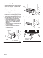
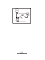
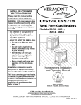
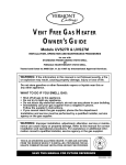
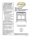
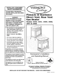
PDV20/SDVR Installation Procedure
– for Pinnacle Direct Vent
Circulating Fan Kit
Installation Instructions
Model: FK28/2960
For use with
Pinnacle PDV20/SDVR Direct Vent,
Stardance/Pinnacle UVS27 Vent Free,
Jefferson Direct Vent, Jefferson Unvented
JUV Gas Heaters and Seville Woodburning
Stove
1. Attach the Snapstat to the Bracket using two #10 x
1/2” phillips screws as shown in Figure 1.
2. Locate and remove the 1/4-20 x 3/8” hex head bolt
installed in the hole in the right rear ledge of the firebox. (A, Fig. 1) Use that bolt to secure the Snapstat
Bracket to the firebox. The mounting hole is slotted to
let you adjust the bracket so that the snapstat head
makes contact with the firebox surface. (Fig. 1)
3. Attach the Fan to the firebox by engaging the upper
flange of the fan skirt under the lower edge of the
Shroud and secure the skirt with the four #10 x 1/2”
Hex Hd Cap screws and one star washer provided.
(Fig. 2)
1/4-20 x 3/8”
Hex Bolt
Read these instructions completely before
beginning installation.
A
WARNING
This appliance is equipped with a three-prong
(grounded) plug for your protection against
shock hazard and should be plugged into a
properly grounded three-prong receptacle. Do
not cut or remove the grounding prong from this
plug.
The Fan Kit FK28/2960 attaches to the rear shroud
of the PDV20/SDVR Direct Vent heater, the UVS27
Unvented, Jefferson Direct Vent, Jefferson JUV
Unvented heaters and the Seville Woodburning Stove.
Installation for the PDV20 should be made after the firebox is set within the stove shell but before connection
to the gas supply. Installation for the UVS27 should be
made before the firebox is set within the shell. Installation for the Jefferson Direct Vent and JUV may be made
at any time during assembly. Installation for the Seville
should be made before the stove is removed from the
shipping pallet. Follow the procedure for the appropriate
firebox model.
Bracket
Snapstat
1/2” Sheet
Metal Screws
Fig. 1 Snapstat assembly and installation. (PDV20 shown)
Rheostat
Control
FK28-1
Upper
Flange
Sheet Metal
Screws (4)
Fig. 2 The upper flange of the fan skirt should be located
behind the lower edge of the shroud. (PDV20 shown)
The kit includes a snapstat sensor which turns the fan
on or off at approximately 109˚F. Be sure the heater is
cool before beginning the installation.
Fan Kit Contents:
•
•
•
•
•
•
#10 x 1/2” Phillips screws, 6
Star Washer
• Wire Tie
Control Knob
• Retaining Nut
Snapstat
• Snapstat Bracket
Blower Assembly w/ Rheostat Control and Snapstat
Silicone Tape
Fig. 3 Correct position of fan skirt installation. (PDV20 shown)
30000275 8/08 Rev. 6
FK28-3
4. The Rheostat Control switch attaches to the Control
Panel plate provided in the parts bag with the stove.
• Insert the switch box shaft through the hole in the
back of the right side of the Panel, aligning the locator pin with the smaller hole in the panel. (Fig. 4)
• Attach the Retaining Nut to the switch control shaft
to secure it to the plate.
• Attach the Control Knob to the rheostat shaft.
• Use the wire tie to secure the fan and rheostat wire
harnesses together to the tubing under the bottom
heat shield.
Do not install the Control Panel onto the stove until
after the gas supply and valve wiring connections have
been made. See Assembly Instructions, PDV20/SDVR
Owner’s Guide.
Rheostat
Control Panel
UVS27 Installation Procedure
– for Stardance and Pinnacle Vent-Free
1. Attach the Fan assembly to the rear shroud in the
same manner as detailed in the preceding section for
the PDV20/SDVR, following Step 3, Figures 2-3.
2. Disconnect the snapstat module from the leads
inside the snapstat bracket. (Fig. 6)
3. Bend open the snapstat bracket. Use your fingers
or needle nose pliers to remove the black plastic
grommet from the bracket. Discard the grommet and
bracket.
4. Feed the snapstat wire lead up between the inner and outer rear shroud panels and secure the
snapstat to the upper right side of the inner shroud.
(Fig. 7)
5. Secure the snapstat wire harness to the shroud panel
using the wire tie provided with this kit.
6. Route the rheostat control switch and wire forward
under the stove. Use the wire tie to secure the fan
and rheostat wire harnesses together to the tubing under the bottom heat shield.
UVS27R / Honeywell Millivolt Valve: Install the
rheostat onto the control panel at the hole to the
right of the valve, as in Figure 4.
UVS27M / SIT Manual Valve: Install the rheostat onto
the bracket to the left of the valve.
Retaining Nut
Control Knob
Pinch Grommet
to Remove
FK28-4
Fig. 4 Attach the Rheostat to the Control Panel.
5. A length of silicone tape is included for installation
between the Top Plate and the Rear Shroud, should
you find that contact between these two surfaces
causes vibration while the fan is operating.
• Remove the Top Plate.
• Cut the self-adhesive tape to size as needed,
remove the backing paper and place tape on the top
edge of the Shroud at those locations where it will
eliminate direct contact between the Shroud and the
Top Plate. (Fig. 5)
• Replace the Top Plate.
Snapstat
Bracket
Snapstat
Module
ST468
Fig. 6 Remove snapstat and grommet from bracket.
ST468
remove
snapstat grommet
9/28/00 djt
Cut pad
to size
and
locate as
needed
Fig. 7 Attach snapstat to inner shroud.
Fig. 5 Vibration dampening pad location. (PDV20 shown)
2
30000275
Jefferson Installation Procedure
1. Attach the snapstat assembly to the snapstat bracket
with two sheet metal screws. (Fig. 8) Remove the
1/4-20 x 3/8” hex head bolt installed in the hole in the
right rear ledge of the firebox. Use that bolt to secure
the snapstat bracket to the firebox. The mounting
hole is slotted to allow you to adjust the bracket so
that the snapstat bracket head makes contact with
the firebox. (Fig. 9)
Upper
Flange
To
Control
Valve
2. Attach the fan to the rear shroud by engaging the
upper flange of the fan skirt under the lower edge of
the shroud and se cure the skirt with the four screws
and one star washer provided. (Fig. 9,10)
3. The rheostat control switch attaches to the left side
of the valve bracket at the front of the stove. (Fig. 11)
•
Remove the plug from the rheostat bracket.
•
Insert the switch box shaft through the hole in
the back of the right side of the valve bracket,
aligning the locator pin with the smaller hole in
that bracket.
•
Attach the retaining nut to the switch control shaft
to secure it to the plate.
•
Attach the control knob to the rheostat shaft.
•
Use the wire tie to secure the fan and rheostat
wire harnesses together.
ST240
Fig. 9 The upper flange of the fan skirt should be located
behind the lower edge of the shroud.
ST240
FDV attach fan
12/13/99 djt
ST241
Fig. 10 Correct position of fan skirt installation.
1/4-20 x 3/8”
Phillips Screw
ST240
FDV attach fan
12/13/99 djt
1/2”
Sheet
Metal
Screw
Rheostat
Retaining Nut
Snapstat
Control Knob
Snapstat Bracket
ST239
Fig. 8 Snapstat assembly and installation.
ST239
FDV attach snapstat
12/13/99 djt
30000275
ST347a
Fig. 11 Attach rheostat.
ST347a
JUV
FK28
rheostat install
9/21/00
3
JUV Installation Procedure
Pinch
Grommet
to Remove
- for Jefferson Unvented
1. Attach the fan to the rear shroud by engaging the
upper flange of the fan skirt under the lower edge of
the shroud and secure the skirt with the four screws
and one star washer provided. (Figs. 12,13)
Snapstat
Bracket
Snapstat
Module
Upper
Flange
ST468
Fig. 14 Remove snapstat and grommet from bracket.
ST468
Snapstat
remove
snapstat grommet
9/28/00 djt
ST240
Fig. 12 Place upper flange behind lower edge of shroud.
ST240
FDV attach fan
12/13/99 djt
ST346a
Fig. 15 Attach snapstat to inner shroud.
Rheostat
ST241
Fig. 13 Correct position of fan skirt installation.
Retaining Nut
2. Disconnect the snapstat module from the leads
inside the snapstat bracket. (Fig. 14)
Control Knob
3.
ST240
Bend open FDV
the attach
snapstat
fan bracket. Use your fingers
12/13/99
djtto remove the black plastic
or needle nose
pliers
grommet from the bracket. Discard the grommet and
bracket.
4. Secure the snapstat to the upper middle of the inner
shroud. (Fig. 15) NOTE: The snapstat location may
be reached through the front of the stove between
the top and the firebox or you may loosen the four
screws holding the rear shroud in place. Be sure to
secure shroud back into place before operation.
5. Connect the two wires to the two snapstat extension
leads attached to the inner shroud. You may coil
excess wire up inside the rear shroud.
6. Route the rheostat control switch and wire forward
under the stove. (Fig. 16) Use the wire tie to secure
the fan and rheostat wire harnesses together to the
tubing under the heater.
4
ST347a
Fig. 16 Attach rheostat to control panel.
ST347a
JUV
FK28
rheostat install
ST346a
9/21/00
install FK28
snapstat JUV
9/21/00
30000275
Seville Installation Procedure
Install the Snapstat
1. Disconnect the leads from the Snapstat terminals.
2. Use pliers to remove the retainer ring from the
Snapstat Cover and slip the cover off the wire harness.
3. Reconnect the wire leads to the Snapstat Plate.
4. Using two sheet metal screws from the fan kit, attach
the Snapstat Plate to the Inner Shroud as indicated
in Figure 17.
Snapstat Plate
ST462
Fig. 18 Install fan body into rear shroud.
Leads
Snapstat
Cover
ST462
seville
Switch Bracket
install
fan
Retainer Nut
ST464
Control Knob
Fig. 17 Install snapstat.
Switch Box
Install the Fan
Position the Fan body within the Rear Shroud as shown
in Figure 18. The Fan’s upper flange should be located
behind the lip of the opening. Secure the Fan to the
Shroud using five sheet metal screws and single star
washer supplied with the kit.
St464
Install the Seville
Rheostat Switch
1. Install the Switch within the Switch Bracket that is
Install snapstat
provided with the stove in the Hardware Bag. Use
the Retainer Nut and Control Knob provided in the
Fan Kit. (Fig. 19)
2. Attach the Switch Bracket to the left side of the Rear
Shroud using two sheet metal screws as shown in
Figure 20.
3. Secure the fan wire harness to the back of the
Shroud using the Wire Tie plug as shown in Figure
20.
30000275
ST463
Fig. 19 Install the rheostat switch.
ST463
Seville
install
Rheostat switch
Insert Wire Tie
Here
ST462
Fig. 20 Attach the rheostat switch and wire tie.
5
BLK
WHT
MOTOR
BLK
WHT
GRN
WHT
BLK
ON/OFF
RHEOSTAT
FK 28 Fan Wiring Diagram
ST236
FK26 wiring diagram
12/99
MHSC
149 Cleveland Drive • Paris, Kentucky 40361
www.mhsc.com
SNAPSTAT