1
Stardance Direct Vent - Rear Vent Gas Heaters
Fuel Conversion Instructions
��
5.
6.
7.
��
CAUTION: The gas supply shall be shut off prior
to disconnecting the electrical power, before
proceeding with the conversion.
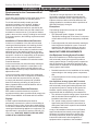
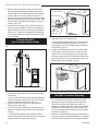
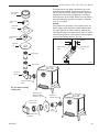
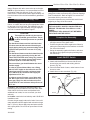
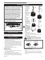
nal key-way of
the screw (Fig.
64), rotate it
Figure 63
Figure
counterclock64
wise until it
is free and
extract it.
Check that the
��
screw is clean
and if necessary remove
��
dirt.
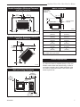
Flip the screw.
Figure 65
(Fig. 65)
Using the Al�����
������������
len wrench as
Figure 66
����
shown in Figure
�����
������������
66, rotate the
����
screw clockwise
and tighten until
��
snug.
WARNING: Do
not overtighten
the screw. Recommended to
grip the wrench
��
by the short
side.
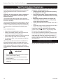
Verify that if the
conversion is from NG to LP, the
screw must be reassembled
�����with the red o-ring vis�����
ible. (Fig. 67)
������������
����������
����
Replace the black protection cap.
����
WARNING: Check that also the pilot and
main burner injectors are appropriate for
the gas type.
��
WARNING! This conversion kit shall be installed
by a qualified service agency in accordance with
the manufacturer’s instructions and all applicable codes and requirements of the authority
having jurisdiction. If the information in these
instructions is not followed exactly, a fire, explosion or production of carbon monoxide may
result causing property damage, personal injury
or loss of life. The qualified service agency is
responsible for the proper installation of this
kit. The installation is not proper and complete
until the operation of the converted appliance
is checked as specified in the manufacturer’s
instructions supplied with the kit.
��
ST226b
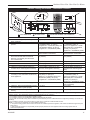
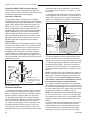
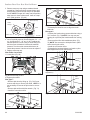
Fig. 62 Attach the gas line to the right side of the valve.
Before proceeding, turn control knob on valve to OFF
ST226b
and turn gas supply OFF. Turn OFF any electricity that
attach gas line
may be going to the appliance.
6/07 djt
Conversion Procedure
1. Remove stove front. Lift stove front up and then
swing bottom out and away to disengage from the
stove body. (Page 43, Fig. 78)
2. Swing open the swiveling latches at the top left and
right corners of the glass frame. (Page 44, Fig. 79)
3. Pull the top edge of the glass and frame assembly
away from the firebox face. Place the assembly out
of the way on a flat, padded surface such as a counter protected by a towel.
4. Remove the logset from the firebox.
Valve Conversion
SDDVR Series Models
1. Turn control knob to the OFF position, and shut off
the gas supply to the valve.
2. Allow the valve to cool to room temperature.
3. Remove the black protection cap by hand. (Fig. 63)
4. Insert a 5/32” or 4 mm Allen wrench into the hexago20012950
8.
9.
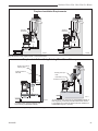
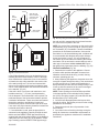
Figure 67
LP Configuration
Natural Gas
Configuration
��
Conversion Precautions
��
Gas Supply Inlet
Main
Gas Line
��
��
Red O-ring Visible
Red O-ring NOT Visible
CO141
SDDVRC Series Models
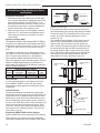
1. Follow procedure for pilot type 2 to replace pilot
orifice.
2. Remove and replace plug on lower right hand side
of the valve; CO141
Red for LP and Blue for NG. (Page 35,
O-ring configuration
Fig. 59)
6/07
39