1
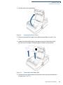
Vx670
Installation Guide
VeriFone Part Number 24003, Revision A
Vx670 Installation Guide
© 2006 VeriFone, Inc.
All rights reserved. No part of the contents of this document may be reproduced or transmitted in any form without the written
permission of VeriFone, Inc.
The information contained in this document is subject to change without notice. Although VeriFone has attempted to ensure the
accuracy of the contents of this document, this document may include errors or omissions. The examples and sample programs are
for illustration only and may not be suited for your purpose. You should verify the applicability of any example or sample program
before placing the software into productive use. This document, including without limitation the examples and software programs, is
supplied “As-Is.”
VeriFone, the VeriFone logo, Omni, VeriCentre, Verix, and ZonTalk are registered trademarks of VeriFone. Other brand names or
trademarks associated with VeriFone’s products and services are trademarks of VeriFone, Inc.
All other brand names and trademarks appearing in this manual are the property of their respective holders.
Comments? Please e-mail all comments on this document to your local VeriFone Support Team.
WARNING
Do not dispose of the Vx670 Li-ion smart battery in a fire. Li-ion batteries must be recycled or
disposed of properly. Do not dispose of Li-ion batteries in municipal waste sites.
VeriFone, Inc.
2099 Gateway Place, Suite 600
San Jose, CA, 95110 USA
www.verifone.com
VeriFone Part Number 24003, Revision A
CONTENTS
PREFACE . . . . . . . . . . . . . . . . . . . . . . . . . . . . . . . . . . . . . . . 5
Audience. . . . . . . . . . . . . . . . . . . . . . . . . . . . . . . . . . . . . . . . . . . . . . . . . . . . . . . .
Organization . . . . . . . . . . . . . . . . . . . . . . . . . . . . . . . . . . . . . . . . . . . . . . . . . . . . .
Related Documentation . . . . . . . . . . . . . . . . . . . . . . . . . . . . . . . . . . . . . . . . . . . .
Conventions and Acronyms . . . . . . . . . . . . . . . . . . . . . . . . . . . . . . . . . . . . . . . . .
Document Conventions. . . . . . . . . . . . . . . . . . . . . . . . . . . . . . . . . . . . . . . . . .
Acronym Definitions . . . . . . . . . . . . . . . . . . . . . . . . . . . . . . . . . . . . . . . . . . . .
5
5
5
6
6
6
CHAPTER 1
Terminal Overview Features and Benefits . . . . . . . . . . . . . . . . . . . . . . . . . . . . . . . . . . . . . . . . . . . . 10
Exceptional Ease of Use. . . . . . . . . . . . . . . . . . . . . . . . . . . . . . . . . . . . . . . .
Performance and Durability . . . . . . . . . . . . . . . . . . . . . . . . . . . . . . . . . . . . .
True Multi-Application Capability . . . . . . . . . . . . . . . . . . . . . . . . . . . . . . . . .
Expandable Communication Capabilities . . . . . . . . . . . . . . . . . . . . . . . . . . .
Wireless Connectivity . . . . . . . . . . . . . . . . . . . . . . . . . . . . . . . . . . . . . . . . . .
Security . . . . . . . . . . . . . . . . . . . . . . . . . . . . . . . . . . . . . . . . . . . . . . . . . . . . .
10
10
11
11
11
11
CHAPTER 2
Terminal Setup Selecting Terminal Location . . . . . . . . . . . . . . . . . . . . . . . . . . . . . . . . . . . . . . . . 13
Environmental Factors . . . . . . . . . . . . . . . . . . . . . . . . . . . . . . . . . . . . . . . . .
Electrical Considerations . . . . . . . . . . . . . . . . . . . . . . . . . . . . . . . . . . . . . . .
Unpacking the Shipping Carton . . . . . . . . . . . . . . . . . . . . . . . . . . . . . . . . . . . . .
Examining Terminal Features. . . . . . . . . . . . . . . . . . . . . . . . . . . . . . . . . . . . . . .
Front Panel . . . . . . . . . . . . . . . . . . . . . . . . . . . . . . . . . . . . . . . . . . . . . . . . . .
Examining Connection Ports . . . . . . . . . . . . . . . . . . . . . . . . . . . . . . . . . . . . . . .
Power Adapter Cable . . . . . . . . . . . . . . . . . . . . . . . . . . . . . . . . . . . . . . . . . .
USB Host Cable . . . . . . . . . . . . . . . . . . . . . . . . . . . . . . . . . . . . . . . . . . . . . .
Multiport Adapter. . . . . . . . . . . . . . . . . . . . . . . . . . . . . . . . . . . . . . . . . . . . . .
USB Modem Dongle . . . . . . . . . . . . . . . . . . . . . . . . . . . . . . . . . . . . . . . . . . .
USB Serial Dongle (RS232 UART). . . . . . . . . . . . . . . . . . . . . . . . . . . . . . . .
Establishing Telephone Line Connections . . . . . . . . . . . . . . . . . . . . . . . . . . . . .
Installing the Paper Roll . . . . . . . . . . . . . . . . . . . . . . . . . . . . . . . . . . . . . . . . . . .
Installing/Replacing MSAM Cards . . . . . . . . . . . . . . . . . . . . . . . . . . . . . . . . . . .
Installing/Replacing SIM Card
(GSM/GPRS Models Only). . . . . . . . . . . . . . . . . . . . . . . . . . . . . . . . . . . . . . . . .
Using the Smart Battery . . . . . . . . . . . . . . . . . . . . . . . . . . . . . . . . . . . . . . . . . . .
Smart Battery Features. . . . . . . . . . . . . . . . . . . . . . . . . . . . . . . . . . . . . . . . .
Battery Behavior (No Power Cord) . . . . . . . . . . . . . . . . . . . . . . . . . . . . . . . . . . .
Manual Startup . . . . . . . . . . . . . . . . . . . . . . . . . . . . . . . . . . . . . . . . . . . . . . .
Manual Shutdown . . . . . . . . . . . . . . . . . . . . . . . . . . . . . . . . . . . . . . . . . . . . .
Installing the Smart Battery . . . . . . . . . . . . . . . . . . . . . . . . . . . . . . . . . . . . . . . .
Removal . . . . . . . . . . . . . . . . . . . . . . . . . . . . . . . . . . . . . . . . . . . . . . . . . . . .
Connecting the Terminal Power Pack . . . . . . . . . . . . . . . . . . . . . . . . . . . . . . . .
Charging the Smart Battery . . . . . . . . . . . . . . . . . . . . . . . . . . . . . . . . . . . . . . . .
Battery Life . . . . . . . . . . . . . . . . . . . . . . . . . . . . . . . . . . . . . . . . . . . . . . . . . .
13
14
14
15
15
16
17
17
18
18
18
19
20
23
24
25
25
26
26
27
27
27
28
29
29
VX670 INSTALLATION GUIDE
3
C ONTENTS
Using the Base Station . . . . . . . . . . . . . . . . . . . . . . . . . . . . . . . . . . . . . . . . . . . .
Standard Base Station . . . . . . . . . . . . . . . . . . . . . . . . . . . . . . . . . . . . . . . . .
Full-Feature Base Station . . . . . . . . . . . . . . . . . . . . . . . . . . . . . . . . . . . . . . .
Powering Up the Base Station . . . . . . . . . . . . . . . . . . . . . . . . . . . . . . . . . . .
Placing the Terminal Onto the Base Station. . . . . . . . . . . . . . . . . . . . . . . . . . . .
Attaching the USB Dongles to the Base Station. . . . . . . . . . . . . . . . . . . . . . . . .
Charging the Spare Battery on the Base Station . . . . . . . . . . . . . . . . . . . . . . . .
Conducting Wireless Transactions . . . . . . . . . . . . . . . . . . . . . . . . . . . . . . . . . . .
Conducting Smart Card Transactions . . . . . . . . . . . . . . . . . . . . . . . . . . . . . . . .
Using the Magnetic Card Reader . . . . . . . . . . . . . . . . . . . . . . . . . . . . . . . . . . . .
30
30
30
31
32
32
33
34
34
35
CHAPTER 3
Specifications Power . . . . . . . . . . . . . . . . . . . . . . . . . . . . . . . . . . . . . . . . . . . . . . . . . . . . . . . . . 37
DC Power Pack . . . . . . . . . . . . . . . . . . . . . . . . . . . . . . . . . . . . . . . . . . . . . . . . . 37
Temperature . . . . . . . . . . . . . . . . . . . . . . . . . . . . . . . . . . . . . . . . . . . . . . . . . . . . 37
External Dimensions. . . . . . . . . . . . . . . . . . . . . . . . . . . . . . . . . . . . . . . . . . . . . . 37
CHAPTER 4
Maintenance Cleaning the Terminal . . . . . . . . . . . . . . . . . . . . . . . . . . . . . . . . . . . . . . . . . . . . 39
Terminal Contacts . . . . . . . . . . . . . . . . . . . . . . . . . . . . . . . . . . . . . . . . . . . . . . . 39
Smart Card Reader . . . . . . . . . . . . . . . . . . . . . . . . . . . . . . . . . . . . . . . . . . . . . . 39
CHAPTER 5
VeriFone Service Returning a Terminal or Smart Battery for Service. . . . . . . . . . . . . . . . . . . . . . . 41
and Support Accessories and Documentation . . . . . . . . . . . . . . . . . . . . . . . . . . . . . . . . . . . . 42
Power Pack. . . . . . . . . . . . . . . . . . . . . . . . . . . . . . . . . . . . . . . . . . . . . . . . . .
Thermal Printer Paper. . . . . . . . . . . . . . . . . . . . . . . . . . . . . . . . . . . . . . . . . .
VeriFone Cleaning Kit . . . . . . . . . . . . . . . . . . . . . . . . . . . . . . . . . . . . . . . . . .
Spare Battery . . . . . . . . . . . . . . . . . . . . . . . . . . . . . . . . . . . . . . . . . . . . . . . .
AVX Host Cable . . . . . . . . . . . . . . . . . . . . . . . . . . . . . . . . . . . . . . . . . . . . . .
Modem Dongle . . . . . . . . . . . . . . . . . . . . . . . . . . . . . . . . . . . . . . . . . . . . . . .
Serial Dongle . . . . . . . . . . . . . . . . . . . . . . . . . . . . . . . . . . . . . . . . . . . . . . . .
Telephone Line Cord . . . . . . . . . . . . . . . . . . . . . . . . . . . . . . . . . . . . . . . . . .
Documentation . . . . . . . . . . . . . . . . . . . . . . . . . . . . . . . . . . . . . . . . . . . . . . .
42
42
42
43
43
43
43
43
43
CHAPTER 6
Troubleshooting Terminal Does Not Start . . . . . . . . . . . . . . . . . . . . . . . . . . . . . . . . . . . . . . . . . . . 45
Guidelines Terminal Display Does not Show Correct/Readable Info . . . . . . . . . . . . . . . . . . 45
Smart Battery Will Not Charge . . . . . . . . . . . . . . . . . . . . . . . . . . . . . . . . . . . . . .
Spare Battery in Base Station Will Not Charge . . . . . . . . . . . . . . . . . . . . . . . . .
Blank Display . . . . . . . . . . . . . . . . . . . . . . . . . . . . . . . . . . . . . . . . . . . . . . . . . . .
Terminal Does Not Dial Out . . . . . . . . . . . . . . . . . . . . . . . . . . . . . . . . . . . . . . . .
Printer Does Not Print. . . . . . . . . . . . . . . . . . . . . . . . . . . . . . . . . . . . . . . . . . . . .
Printer Paper Jam. . . . . . . . . . . . . . . . . . . . . . . . . . . . . . . . . . . . . . . . . . . . . . . .
Keypad Does Not Respond . . . . . . . . . . . . . . . . . . . . . . . . . . . . . . . . . . . . . . . .
Transactions Fail To Process . . . . . . . . . . . . . . . . . . . . . . . . . . . . . . . . . . . . . . .
46
46
46
46
47
47
47
47
I N D E X . . . . . . . . . . . . . . . . . . . . . . . . . . . . . . . . . . . . . . . . . 49
4
VX670 INSTALLATION GUIDE
PREFACE
This guide is your primary source of information for setting up and installing the
Vx670 terminal.
Audience
Organization
This guide is useful for anyone installing and configuring a Vx670 terminal. Basic
descriptions of the terminal features are also provided.
This guide is organized as follows:
Chapter 1, Terminal Overview. Provides an overview of the Vx670 terminal.
Chapter 2, Terminal Setup. Explains how to set up and install the Vx670 terminal.
It tells you how to select a location, establish power and telephone line
connections, and how to configure optional peripheral devices.
Chapter 3, Specifications. Discusses power requirements and dimensions of the
Vx670 terminal.
Chapter 4, Maintenance. Explains how to maintain your Vx670 terminal.
Chapter 5, VeriFone Service and Support. Provides information on contacting
your local VeriFone representative or service provider, and information on how to
order accessories or documentation from VeriFone.
Chapter 6, Troubleshooting Guidelines. Provides troubleshooting guidelines,
should you encounter a problem in terminal installation and configuration.
Related
Documentation
To learn more about the Vx670 terminal, refer to the following set of documents:
Vx670 Certifications and Regulations Sheet
VPN 24000
Vx670 Quick Installation Guide
VPN 24001
Vx670 Reference Manual
VPN 24004
Vx670 Base and Dongle Quick Installation Guide
VPN 24005
Vx670 Standard Base Quick Installation Guide
VPN 24006
Verix V Operating System Programmer’s Manual
VPN 23230
Verix V Tools Programmer’s Manual
VPN 23231
VX670 INSTALLATION GUIDE
5
P REFACE
Conventions and Acronyms
Conventions and
Acronyms
This section describes the conventions and acronyms used in this guide.
Document Various conventions are used to help you quickly identify special formatting. Table
Conventions 1 describes these conventions and provides examples of their use.
Table 1
Document Conventions
Convention
Meaning
Example
Blue
Text in blue indicates terms
that are cross referenced.
See Conventions and Acronyms.
Italics
Italic typeface indicates
book titles or emphasis.
You must install a roll of thermalsensitive paper in the printer.
Courier
The courier type face is
used while specifying
onscreen text, such as text
that you would enter at a
command prompt, or to
provide an URL.
http://www.verifone.com
The pencil icon is used to
highlight important
information.
RS-232-type devices do not work
with the PINpad port.
The caution symbol
indicates possible hardware
or software failure, or loss
of data.
The terminal is not waterproof or
dustproof, and is intended for indoor
use only.
The lightning symbol is
used as a warning when
bodily injury might occur.
Due to risk of shock do not use the
terminal near water.
NOTE
CAUTION
WARNING
Acronym Definitions Various acronyms are used in place of the full definition. Table 2 presents
acronyms and their definitions.
Table 2
6
VX670 INSTALLATION GUIDE
Acronym Definitions
Acronym
Definitions
AC
Alternating Current
ATM
Automated Teller Machine
CDMA
Code Division Multiple Access
CR
Check Reader
EMV
Europay MasterCard and VISA
GPRS
General Packet Radio Service
GSM
Global System for Mobile Communication
ITP
Internal Thermal Printer
P REFACE
Conventions and Acronyms
Table 2
Acronym Definitions (continued)
Acronym
Definitions
LCD
Liquid Crystal Display
LED
Light Emitting Diode
MRA
Merchandise Return Authorization
MSAM
Micromodule-Size Security Access Module
PED
PIN-Entry Devices
PIN
Personal Identification Number
RJ45
Registered Jack 45
RS-232
Recommended Standard 232
SAM
Security Access Module
SIM
Subscriber Identity Module
UART
Universal Asynchronous Transmitter/Receiver
USB
Universal Serial Bus
VPN
VeriFone Part Number
Wi-Fi
Wireless Fidelity
VX670 INSTALLATION GUIDE
7
P REFACE
Conventions and Acronyms
8
VX670 INSTALLATION GUIDE
CHAPTER 1
Terminal Overview
This chapter provides a brief description of the Vx670 terminal. The Vx670
terminal represents a revolution for e-payment. The Vx670 device uses a bold
ergonomic design that is sleek and stylish, offering countertop power and 32-bit
performance in an integrated terminal that can be handed to the consumer for
input, making it ideal for pay-at-table usage.
The Vx670 terminal is a portable, battery-powered device that uses wireless
technologies, including Wi-Fi with 802.11g technology and GSM/GPRS. It also
features a 128-by-128 pixel display and a speedy thermal printer.
NOTE
VeriFone ships variants of the Vx670 terminal for different markets. Your terminal
may have a different configuration. The following devices may or may not be
present: a smart card reader, zero or three MSAM cardholders, and/or a SIM
cardholder.
Figure 1
The Vx670 terminal.
VX670 INSTALLATION GUIDE
9
TERMINAL O VERVIEW
Features and Benefits
Features at a glance
• 32-bit ARM9 processor delivers
power and usability in a convenient
“hand-over” design.
• Multi-application operating
environment.
• 32-bit processing and multi-tasking
capabilities.
• USB support for VeriFone peripheral
devices.
• Offers unsurpassed performance on
EMV smart card transactions.
• Security architecture meets
specifications for PCI-PED and
sophisticated file authentication.
• Max UI design provides large display
on small footprint.
• Designed to meet the needs of
VeriFone solutions reduces
development costs.
TablePAY, DeliveryPAY, and
CarsidePAY markets.
breakage.
• Spill resistant design forces liquid
down and off the front of the terminal.
Vx670 terminals provide the right combination of features and functions. This
includes a triple-track magnetic-stripe card reader, smart card reader, integrated
PINpad, and a quiet yet fast internal thermal printer (ITP).
Exceptional Ease of •
Use
Lightweight (less than 1 pound), tapered design is compact and stylish and the
ergonomic balance allows for convenient terminal hand-off to the consumer
for PIN entry or other input.
•
128-by-128 pixel display with anti-glare, adjustable contrast, dimming
capability, intuitive ATM-style interface, and oversized menu prompts simplify
training and reduce calls to the helpdesk.
•
Large, well-placed, blue backlit keys provide improved tactile response to
simplify usage and minimize finger slips.
•
Integrated high-speed thermal printer prints quickly and silently, and simplified
paper loading virtually eliminates paper jams.
•
Triple-track, high-coercivity card reader handles most magnetic stripe cards.
•
Optional Base Station with battery charger supports connectivity to a UART
module or a 14,400 bps modem via USB dongles.
•
Accepts all types of payments – including debit.
Performance and •
Durability
10
and value-added applications.
• Backward compatibility with
• Drop resistant design minimizes
Features and
Benefits
• Securely supports and runs payment
VX670 INSTALLATION GUIDE
32-bit processing and multi-tasking capabilities make short work of payment,
payment-related, and value-added applications.
•
Exceptional graphics-handling capabilities of display and printer quickly render
logos, graphical fonts, and character-based languages.
•
VeriCentre Appliance Management Suite employs advanced file compression
to streamline simultaneous downloads of application software to hundreds of
terminals.
•
Rounded corners and drop-resistant design minimizes breakage.
TERMINAL O VERVIEW
Features and Benefits
•
Sealed MSR blade locks out moisture for excellent spill resistance.
•
Innovative design resists spills by forcing liquid down and off the front of the
terminal
•
Integrated PINpad offers added convenience to handle PIN-based
applications.
•
Uncompromising reliability from VeriFone, the worldwide leader in
e-payment.
•
Complies with RoHS (Restriction of Hazardous Substances) directive of the
European Union.
True Multi- •
Application
Capability
•
6 MB of memory and the Verix V OS dynamic memory allocation support two
or three typical-sized applications on a single terminal.
•
Vx670 series of terminals and SoftPay EMV software have received EMV
Level 1 and Level 2 Type approval for smart card solutions. Verix EMV Library
provides efficient development of other EMV-compliant applications.
•
VeriShield security architecture meets published specifications for PCI-PED
and provides sophisticated file authentication to prevent execution of
Primary smart card reader and MSAMs safeguard sensitive financial data and
support multiple smart card schemes.
unauthorized software on Vx670 terminals.
Expandable •
Communication •
Capabilities
•
USB Host Port
USB Device Port for application debugging
RS-232, Serial Port
•
14,400 bps Modem
•
Universal Asynchronous Receiver/Transmitter (UART) port
Wireless •
Connectivity
•
Security •
•
Customers are not tied to a fixed location with the Vx670 wireless terminals –
the point of payment can be almost anywhere.
“Always-on” wireless connection uses the latest wireless technologies,
including GSM/GPRS and Wi-Fi with 802.11g technology for faster
transmission and enhanced compatibility with access points and routers.
WPA-PSK (pre-shared keys) protects Wi-Fi transactions.
Other security features include tamper-resistant construction, adoption of SSL
protocols, and VeriShield file authentication.
VX670 INSTALLATION GUIDE
11
TERMINAL O VERVIEW
Features and Benefits
12
VX670 INSTALLATION GUIDE
CHAPTER 2
Terminal Setup
This chapter describes the terminal setup procedure. You will learn about:
Selecting
Terminal
Location
•
Selecting Terminal Location.
•
Unpacking the Shipping Carton.
•
Examining Terminal Features.
•
Examining Connection Ports.
•
Establishing Telephone Line Connections.
•
Installing the Paper Roll.
•
Installing/Replacing MSAM Cards.
•
Installing/Replacing SIM Card (GSM/GPRS Models Only).
•
Using the Smart Battery.
•
Battery Behavior (No Power Cord).
•
Installing the Smart Battery.
•
Charging the Smart Battery.
•
Connecting the Terminal Power Pack.
•
Using the Base Station.
•
Placing the Terminal Onto the Base Station.
•
Attaching the USB Dongles to the Base Station.
•
Charging the Spare Battery on the Base Station.
•
Conducting Wireless Transactions.
•
Conducting Smart Card Transactions.
•
Using the Magnetic Card Reader.
Use the following guidelines when selecting a location for your Vx670 terminal.
Environmental •
Factors
•
The Vx670 is a portable terminal. Select a flat support surface, such as a
countertop or table, to keep the terminal safe in between uses.
Do not use the terminal where there is high heat, dust, humidity, moisture, or
caustic chemicals or oils.
VX670 INSTALLATION GUIDE
13
TERMINAL S ETUP
Unpacking the Shipping Carton
CAUTION
•
Keep the terminal away from direct sunlight and anything that radiates heat,
such as a stove or motor.
•
Do not use the terminal outdoors.
The terminal is not waterproof or dustproof, and is intended for indoor use only.
Any damage to the unit from exposure to rain or dust may void any warranty.
Electrical •
Considerations •
•
Unpacking the
Shipping Carton
Avoid using this product during electrical storms.
Avoid locations near electrical appliances or other devices that cause
excessive voltage fluctuations or emit electrical noise (for example, air
conditioners, electric motors, neon signs, high-frequency or magnetic security
devices, or computer equipment).
Do not use the terminal near water or in moist conditions.
Open the shipping carton and carefully inspect its contents for possible tampering
or shipping damage. The Vx670 is a secure product and any tampering may
cause the terminal to cease to function properly.
To unpack the 1
Shipping Carton
Remove and inspect the following items:
•
Terminal
•
Power pack
•
Telephone line cord
•
Power cord
•
Battery pack
•
Paper roll
2 Remove all plastic wrapping from the terminal and other components.
3 Remove the clear protective film from the LCD screen.
CAUTION
Do not use a terminal that has been damaged or tampered with. The
Vx670 terminal comes equipped with tamper-evident labels. If a label or
component appears damaged, please notify the shipping company and your
VeriFone representative or service provider immediately.
4 Save the shipping carton and packing material for future repacking or moving
the terminal.
14
VX670 INSTALLATION GUIDE
TERMINAL S ETUP
Examining Terminal Features
Examining
Terminal
Features
Before you continue the installation process, notice the features of the
Vx670 terminal (see Figure 2).
INTERNAL THERMAL
PRINTER (AT THE BACK)
INDICATOR LED
ATM-STYLE FUNCTION
KEYS
MAGNETIC CARD
READER
TERMINAL DISPLAY
PROGRAMMABLE
FUNCTION KEYS
ALPHA KEY
TELEPHONE-STYLE
KEYPAD
ENTER KEY
CANCEL KEY
CLEAR KEY
SMART CARD READER
Figure 2
Vx670 Terminal Features (Front Panel)
Front Panel The front panel includes the following features:
•
A terminal display, backlit LCD screen.
•
Five types of keys:
a A 12-key, telephone-style keypad (keypads may vary in style).
b Six ATM-style function keys, labeled F0 to F5, to the right of the LCD
screen.
c Four programmable function keys above the keypad.
d Three color-coded function keys below the
keypad (icons at right; from left to right: CANCEL,
CLEAR, ENTER).
e An ALPHA key centered at the top of the keypad.
VX670 INSTALLATION GUIDE
15
TERMINAL S ETUP
Examining Connection Ports
•
A magnetic card reader, built into the right side. Swipe the card using the
proper direction, with the magnetic stripe down and facing inward, toward the
keypad.
•
A green indicator LED indicates power is ON.
•
An internal thermal printer at the back of the terminal.
•
A smart card reader, built into the front of the terminal. For directions on how
to use a smart card, see Conducting Smart Card Transactions.
•
A SAM (security access module) compartment, built into the bottom of the
terminal. The Vx670 terminal contains MSAM cardholders to support multiple
stored-value card programs or other merchant card requirements.
NOTE
Examining
Connection
Ports
VeriFone ships variants of the Vx670 terminal for different markets. Your terminal
may have a different configuration. The following devices may or may not be
present: a smart card reader, or zero or three MSAM cardholders. However, the
basic processes described in this guide remain the same, regardless of terminal
configuration.
The Vx670 terminal has one primary port that supports different peripherals
through the use of various cables.
Figure 3
16
VX670 INSTALLATION GUIDE
The Vx670 Primary Port (Bottom View)
TERMINAL S ETUP
Examining Connection Ports
Power Adapter Each Vx670 terminal comes with a power adapter cord that completes the
Cable connection between the power pack and the terminal.
Figure 4
Power Adapter Cable Connection to a Vx670 Terminal
USB Host Cable A 2-Wire USB Host port for external peripherals. A connector adaptor provides for
standard USB host connection for the Modem Dongle or the RS232 UART
Dongle.
Figure 5
USB Host Cable Connection to a Vx670 Terminal
VX670 INSTALLATION GUIDE
17
TERMINAL S ETUP
Examining Connection Ports
Multiport Adapter An adapter that provides connectivity for power, USB Host, USB Device, and
COM1 (RS232 UART). This cable is used primarily for deployment or
development purposes.
Figure 6
NOTE
Multiport Adapter Connection to a Vx670 Terminal
Other cables are available for development purposes. Check with your local
VeriFone representative for further information.
USB Modem Dongle A modem in the form of a USB Modem Dongle may be provided with the Vx670
terminal. The USB Modem Dongle provides communication via a telephone line at
speeds of up to 14,400 bps. It can also be connected to the full-feature Base
Station when the terminal is in the station (see Attaching the USB Dongles to the
Base Station).
USB Serial Dongle The USB Serial Dongle may be provided with the Vx670 terminal. It is designed to
(RS232 UART) accommodate the RJ45 connector. The USB Serial Dongle can also be
connected to the full-feature Base Station when the terminal is placed in the
station (see Attaching the USB Dongles to the Base Station).
NOTE
18
VX670 INSTALLATION GUIDE
A Base Station may be provided with the Vx670 terminal. A full-feature Base
Station has two USB host ports for external dongles as well as a battery charger
slot for charging an extra lithium-ion battery pack. A standard Base Station does
not have any USB ports and is capable of charging the terminal only and not the
extra battery pack.
TERMINAL S ETUP
Establishing Telephone Line Connections
CAUTION
The Modem Dongle and Serial Dongle are intended for use with the Vx670
terminal and Base Station only. They should not be installed or used with any
equipment other than the Vx670 terminal or Base Station.
Establishing To connect a telephone line:
Telephone Line 1 Connect one end of the telephone cord to the USB Modem Dongle.
Connections
2 Connect the USB Modem Dongle to the terminal using the AVX Connector
(VPN 24223-01-R).
3 Route the other end of the telephone cord directly to a telephone wall jack.
WARNING
To reduce the risk of fire, use only No. 26 AWG or larger UL Listed or CSA
Certified Telecommunication Line Cord.
USB HOST CABLE
USB MODEM DONGLE
Figure 7
Vx670 USB Modem Dongle Connection
VX670 INSTALLATION GUIDE
19
TERMINAL S ETUP
Installing the Paper Roll
Installing the
Paper Roll
A fast, quiet thermal printer is built into the Vx670 terminal. Before you can
process transactions that require a receipt or record, you must install a roll of
thermal-sensitive paper in the printer.
The ITP uses a roll of single-ply, thermal-sensitive paper 57 millimeters (2.24
inches) wide and 38 millimeters in diameter. A pink out-of-paper indicator line
appears on the edge of the paper approximately 18 inches before the end of the
roll. After this line appears, there is enough paper remaining on the roll to
conclude at least one transaction.
CAUTION
Poor-quality paper can jam the printer and create excessive paper dust. To order
high-quality VeriFone paper, refer to Accessories and Documentation.
Store thermal paper in a dry, dark area. Handle thermal paper carefully: impact,
friction, temperature, humidity, and oils affect the color and storage
characteristics of the paper.
Never load a roll of paper with folds, wrinkles, tears, or holes at the edges in the
print area.
To Install a Paper Roll 1
Gently pull the latch located on the bottom of the terminal to unlock the paper
roll cover.
Figure 8
20
VX670 INSTALLATION GUIDE
Unlocking the Printer Cover
TERMINAL S ETUP
Installing the Paper Roll
2 Lift the printer cover up and back.
Figure 9
Opening the Printer Cover
3 Remove any partial roll of paper in the printer tray by lifting it up (see Figure
10).
4 Loosen the glued leading edge of the paper or remove the protective strip
from the new roll of paper. Unwind the paper roll past any glue residue.
Figure 10
Removing Partial Paper Roll
5 Hold the roll so the paper feeds from the bottom of the roll when the terminal is
inverted (see Figure 12).
VX670 INSTALLATION GUIDE
21
TERMINAL S ETUP
Installing the Paper Roll
6 Drop the paper roll into the printer tray.
Figure 11
Loading Paper Roll
7 Pull paper up past the glue residue on the paper roll.
8 Close the paper roll cover by gently pressing directly on the cover until it clicks
shut, allowing a small amount of paper past the glue residue to extend outside
the printer door.
CAUTION
To prevent damaging the print roller, always gently press down on the paper roll
cover to close it.
Figure 12
22
VX670 INSTALLATION GUIDE
Closing Paper Roll Cover
TERMINAL S ETUP
Installing/Replacing MSAM Cards
9 Tear the paper off against the serrated plastic strip in the printer.
Installing/
Replacing MSAM
Cards
When you first receive your Vx670 terminal, you may need to install one or more
MSAM cards or you may need to replace old cards.
CAUTION
Observe standard precautions when handling electrostatically sensitive devices.
Electrostatic discharges can damage this equipment. VeriFone recommends
using a grounded anti-static wrist strap.
To Install/Replace 1
MSAMs
Power off the terminal.
CAUTION
It is very important that the terminal is powered off before removing the battery.
2 Place the terminal upside down on a soft, clean surface to protect the lens
from scratches.
3 Remove the battery.
Figure 13
Removing the Smart Battery
4 After removing the battery, the MSAM compartments are exposed.
5 Remove any previously installed MSAM card by sliding the card from the
MSAM cardholder.
VX670 INSTALLATION GUIDE
23
TERMINAL S ETUP
Installing/Replacing SIM Card (GSM/GPRS Models Only)
6 Install an MSAM card by aligning the card and carefully sliding it within the
guides on the cover until it is fully inserted (see Figure 14). The MSAM card
holders are labeled MSAM1, MSAM2, and MSAM3.
Figure 14
NOTE
Installing MSAM Card
Before inserting the MSAM card, position it as shown in Figure 14, with the card’s
gold contacts facing the smart card reader end of the terminal. The cardholder
connector base has a set of contacts and a notch on one corner to ensure the
MSAM card is positioned correctly. The MSAM card has a notch on one corner to
ensure that it fits into the connector base in only one way. The MSAM
compartment door will not close properly if the MSAM cards are installed
incorrectly.
7 Install the battery (see Figure 17).
Installing/ The Vx670 terminal supports the installation of a SIM (Subscriber Identity Module)
Replacing SIM card. Use the following procedure to replace or install a SIM card.
Card 1 Place the terminal upside down on a soft, clean surface to protect the lens
(GSM/GPRS
from scratches.
Models Only)
2 Remove the battery.
Figure 15
Removing the Smart Battery
3 After removing the battery, the SIM compartment is exposed. The SIM card
holder is labeled RADIO SIM.
24
VX670 INSTALLATION GUIDE
TERMINAL S ETUP
Using the Smart Battery
4 Insert the SIM into the cardholder.
NOTE
There is only one SIM slot, but there are multiple SAM slots. Make sure you insert
the SIM card into the SIM slot, as shown in Figure 16.
Figure 16
Inserting SIM Card
5 Install the battery (see Figure 17).
Using the Smart
Battery
NOTE
The Vx670 terminal uses an Li-ion smart battery (see Accessories and
Documentation for ordering information). The internal logic of the smart battery
prevents both overcharging and undercharging (a fault condition in which the
battery level goes well below the minimum acceptable charge and the battery
becomes unusable).
The Vx670 terminal will operate on battery power or on power pack power. The
smart battery charger in the terminal will be active whenever the power pack is
connected.
Smart Battery The following are features of the smart battery:
Features
• Two Li-ion cells
•
•
A fuel gauge module that:
•
monitors state of charge (voltage and percentage of capacity),
•
communicates with the terminal (charge parameters and status),
•
determines full charge capacity (on charge cycle and uninterrupted
discharge cycle), and
•
automatically shuts down when cell voltage is extremely low.
A safety circuit that:
•
prevents cell damage from overcharge, over-discharge, or overheating,
and
VX670 INSTALLATION GUIDE
25
TERMINAL S ETUP
Battery Behavior (No Power Cord)
•
NOTE
Battery Behavior
(No Power Cord)
activates when the battery is left in an unused terminal for extended
periods.
•
Lithium-ion batteries are not affected by shallow charging. Furthermore, when
the terminal has no external power source or battery the coin cell battery
provides power to the security circuit.
•
Uninstalling the battery and unplugging the terminal power pack reduce the
life of the coin cell battery, which does not recharge and must be replaced if
drained.
•
Conserve battery power by turning the Vx670 terminal off when not in use. If
the terminal is not to be used for an extended period of time, keep the Lithiumion battery inserted in the terminal, and power up the terminal periodically to
check the battery charge. Do not let the battery charge fall below 10% for
extended periods of time as this may permanently diminish the battery
capacity. Recharge the battery by attaching the power cord to the terminal and
plugging the power pack into a wall outlet.
If you connect the Vx670 to a non-battery power source, the terminal shifts to
corded power mode and starts up automatically, regardless of the battery charge
state.
Manual Startup Hold the green key down for about 4 seconds until the terminal displays the
startup screen.
NOTE
The 4-second power-up delay is for preventing terminal startup if the green key is
accidentally held down. The time required to hold the green key down to power up
the terminal is configurable (for more information, see the Vx670 Reference
Manual – VPN 24004).
When the terminal has power, the terminal lights are activated and the green LED
indicator remains lit.
NOTE
26
VX670 INSTALLATION GUIDE
If an application is loaded in the terminal, it starts after the initial VeriFone
copyright screen and usually displays a unique copyright screen. If no application
is loaded in the terminal, DOWNLOAD NEEDED appears on screen after the initial
VeriFone copyright screen.
TERMINAL S ETUP
Installing the Smart Battery
Manual Shutdown Hold the red key down for about 4 seconds until the terminal displays the
shutdown verification screen. Keep holding the red key until the Vx670 terminal
shuts down.
NOTE
•
The 4-second shutdown delay is for preventing terminal shutdown if the red
key is accidentally held down. The time required to hold the red key down to
shut down the terminal is configurable (for more information, see the Vx670
Reference Manual – VPN 24004).
•
Installing the
Smart Battery
When the terminal has no power, the screen is blank and the green LED
indicator is not lit.
The Vx670 smart battery fits in a slot on the back of the Vx670 terminal, as shown
in Figure 17. The locking tab clicks when the battery is in place. The slot is keyed,
so that there is only one way to insert the battery.
Figure 17
Installing the Smart Battery
Removal To remove the Vx670 smart battery, press the locking tab and pull the smart
battery from its slot.
Figure 18
Detaching the Smart Battery from the Vx670 Terminal
VX670 INSTALLATION GUIDE
27
TERMINAL S ETUP
Connecting the Terminal Power Pack
Connecting the
Terminal Power
Pack
When you have finished installing the smart battery, you are ready to connect the
CAUTION
Using an incorrectly rated power supply may damage the terminal or cause it not
to work as specified. Before troubleshooting, ensure that the power supply being
used to power the terminal matches the requirements specified on the bottom of
the terminal. (See Chapter 3, Specifications, for detailed power supply
specifications.) Obtain the appropriately rated power supply before continuing
with troubleshooting.
Vx670 terminal to the provided power source for initial charging.
The Vx670 unit comes with a universal input power pack capable of operating
from voltages of 100VAC to 240VAC.
To Connect the 1
Terminal Power Pack
Insert the round barrel connector into the power port in the connector, as
shown in Figure 19.
Figure 19
Vx670 Power Pack Connection
2 Insert the AC power cord into the power pack.
3 Plug the AC power cord into a wall outlet or powered surge protector.
WARNING Do not plug the power pack into an outdoor outlet or operate the terminal
outdoors.
During a transaction, disconnecting the power by removing the battery or
unplugging the terminal from a wall power while at very low battery charge may
cause transaction data files not yet stored in the terminal memory to be lost.
NOTE
To protect against possible damage caused by lightning strikes and electrical
surges, consider installing a power surge protector.
When the terminal has power, the terminal lights are activated and the LED
indicator remains lit.
28
VX670 INSTALLATION GUIDE
TERMINAL S ETUP
Charging the Smart Battery
If an application is loaded in the terminal, it starts after the initial VeriFone
copyright screen and usually displays a unique copyright screen. If no application
is loaded in the terminal, DOWNLOAD NEEDED appears on screen after the initial
VeriFone copyright screen.
Charging the
Smart Battery
NOTE
After unpacking your Vx670 terminal, install the battery and connect the power
pack to the unit for 6 hours or until fully charged.
The Vx670 terminal’s smart battery is also charged when the terminal is in the
Base Station. For more information, see Placing the Terminal Onto the Base
Station.
The smart battery has a safety circuit to protect the Li-ion cells from overcharging
and over-discharging. If the battery is over-discharged, the safety circuit shuts
down the battery. The battery must then be recharged to restore operation.
NOTE
The Vx670 terminal automatically shuts off when the smart battery reaches the
critically low charge state. If this occurs, the smart battery must be recharged for a
minimum of 1/2 hour before it can power the terminal. It may take several
recharge attempts to reset the safety circuit when charging a smart battery that
has been discharged below this critical state.
Battery Life The Vx670 smart battery can be charged and discharged hundreds of times, but
will eventually wear out. When operating times are noticeably shorter than usual,
it is time to buy a new battery (see Accessories and Documentation for ordering
information).
WARNING Do not dispose of batteries in a fire. Li-ion batteries must be recycled
or disposed of properly. Do not dispose of Li-ion batteries in municipal
waste sites.
VX670 INSTALLATION GUIDE
29
TERMINAL S ETUP
Using the Base Station
Using the Base
Station
The primary purpose of the Base Station is to charge the terminal battery and
provide a docking station for the terminal after being used in pay-at-table
environments. The Base Station can be positioned on a countertop or mounted to
the wall.
There are two types of Base Stations, the standard model and the full-feature
model.
Standard Base The standard Base Station can charge the Vx670 terminal. However, it does not
Station have any external ports and has a single LCD to indicate power status.
Figure 20
The Vx670 Standard Base Station
Full-Feature Base The full-feature Base Station can charge the Vx670 terminal while charging an
Station extra battery pack. In addition, it has two USB ports for external dongles, together
with one LED for power indication and another LED for the charger status.
Figure 21
30
VX670 INSTALLATION GUIDE
The Vx670 Full-Feature Base Station
TERMINAL S ETUP
Using the Base Station
For more information on charging the spare battery on the full-feature Base
Station and connecting external dongles to the USB ports, see Charging the
Spare Battery on the Base Station and Attaching the USB Dongles to the Base
Station.
Powering Up the Use the procedure in this section to connect the Vx670 Base Station to a power
Base Station source.
1 Insert the round barrel connector of the power pack into the power port at the
back of the Base Station.
Figure 22
Connecting the Base Station to a Power Source
2 Insert the AC power cord into the power pack.
3 Plug the AC power cord into a wall outlet or power surge protector.
4 Confirm that the Base Station is powered up as indicated by the solid green
LED.
VX670 INSTALLATION GUIDE
31
TERMINAL S ETUP
Placing the Terminal Onto the Base Station
Placing the
Terminal Onto
the Base Station
The Vx670 terminal can be placed on the Base Station when not in use or to
charge the battery. External peripherals can also be attached to the terminal via
USB dongles while it is on the Base Station (see Attaching the USB Dongles to
the Base Station).
Figure 23
NOTE
Placing the Vx670 onto the Base Station
The full-feature Base Station can also charge a spare battery while it charges the
battery attached to the terminal (see Charging the Spare Battery on the Base
Station).
To protect against possible damage caused by lightning strikes and electrical
surges, consider installing a power surge protector.
WARNING Do not plug the power pack into an outdoor outlet or operate the terminal
outdoors.
Disconnecting the power during a transaction may cause transaction data files
not yet stored in terminal memory to be lost.
Attaching the
USB Dongles to
the Base Station
NOTE
32
VX670 INSTALLATION GUIDE
While the Vx670 terminal is resting on the Base Station, you can drive external
peripherals through the use of USB dongles. Only one Modem Dongle and one
Serial Dongle can be connected to the Base Station. A second Modem Dongle or
a second Serial Dongle will be ignored by the terminal.
The full-feature Base Station has USB ports for two external dongles. The
standard Base Station does not have USB ports.
TERMINAL S ETUP
Charging the Spare Battery on the Base Station
1 Insert the USB dongle into the USB port located at the back of the Base
Station.
Figure 24
Inserting External Dongle Into USB Port
2 After inserting the external dongle into the USB port, place the Vx670 terminal
onto the Base Station (see Powering Up the Base Station).
3 Connect the peripheral to the external dongle.
Charging the The full-feature Base Station can charge the Vx670 terminal while charging an
Spare Battery on extra battery pack.
the Base Station 1 Connect the Base Station to a power source (see Powering Up the Base
Station)
2 Place the spare battery pack onto the Base Station as shown in Figure 25.
Figure 25
Putting Spare Battery Pack Into the Base Station
VX670 INSTALLATION GUIDE
33
TERMINAL S ETUP
Conducting Wireless Transactions
3 Place the Vx670 terminal onto the Base Station to charge both the spare and
installed battery packs at the same time.
Figure 26
Charging the Spare and Installed Battery Simultaneously
Conducting To conduct a wireless transaction:
Wireless • Ensure the terminal is in an optimal position for transmitting.
Transactions
•
Conducting
Smart Card
Transactions
Follow the on-screen instructions provided with your application.
The smart card transaction procedure may vary from one application to another.
Verify the procedure with your application provider before performing a smart card
transaction.
To Conduct a Smart 1
Card Transaction
Position a smart card with the contacts facing upward (see Figure 27).
2 Insert the smart card into the smart card reader slot in a smooth, continuous
motion until it seats firmly.
34
VX670 INSTALLATION GUIDE
TERMINAL S ETUP
Using the Magnetic Card Reader
3 Remove the card only when the application indicates the transaction is
complete.
Figure 27
CAUTION
Using the
Magnetic Card
Reader
Inserting a Smart Card
Leave the smart card in the card reader until the transaction is complete.
Premature card removal will invalidate the transaction.
The Vx670 terminal supports credit/debit card transactions.
To Conduct a Credit/ 1
Debit Card
Transaction
Position a magnetic card with the stripe in the card reader and facing inward,
toward the keypad.
2 To ensure a proper read of the magnetic swipe card, the user should insert the
magnetic card from the top of the unit, as shown in Figure 28.
VX670 INSTALLATION GUIDE
35
TERMINAL S ETUP
Using the Magnetic Card Reader
3 Swipe the card through the magnetic card reader.
Figure 28
36
VX670 INSTALLATION GUIDE
Using the Magnetic Card Reader
CHAPTER 3
Specifications
This chapter discusses power requirements, dimensions, and other specifications
of the Vx670 terminal.
Power
DC Power Pack
Vx670 terminal: 12V DC 2.0 A
UL, ITE listed, Class 2 power supply:
a Input rated: 100 - 240V AC, 50/60 Hz
b Output rated: 12V DC 2.0 A
Barrel connector polarity:
Temperature •
Operating temperature: 0° to 40° C (32° to 104° F)
•
Storage temperature: -30° to + 60° C (-22° to 140° F)
•
Relative humidity: 5% to 90%; non-condensing
External For Vx670 Terminals:
Dimensions • Length: 169 mm (6.7 in)
•
Width: 81 mm (3.2 in)
•
Depth: 60 mm (2.4 in)
VX670 INSTALLATION GUIDE
37
S PECIFICATIONS
External Dimensions
38
VX670 INSTALLATION GUIDE
CHAPTER 4
Maintenance
The Vx670 terminal and base stations have no user-maintainable parts.
Cleaning the
Terminal
To clean the terminal and base station, use a clean cloth slightly dampened with
water and a drop or two of mild soap. For stubborn stains, use alcohol or an
alcohol-based cleaner.
CAUTION Never use thinner, trichloroethylene, or ketone-based solvents – they may cause
deterioration of plastic or rubber parts.
Do not spray cleaners or other solutions directly onto the keypad or terminal
display.
Terminal
Contacts
Gently swab the contacts with alcohol or contact cleaner to remove the dirt. It is
important that the exposed contacts of the Vx670 battery stay clean and unbent.
x
CAUTION Avoid touching the contacts of the V 670 battery and the recessed area on the
terminal. Finger oils tarnish contacts, causing bad connections. When operating
on battery power and experiencing a high occurrence of bad or incomplete data
transfers, clean the contacts.
Smart Card
Reader
Do not attempt to clean the smart card reader. Doing so may void any warranty.
For smart card reader service, contact your VeriFone distributor or service
provider.
VX670 INSTALLATION GUIDE
39
M AINTENANCE
Smart Card Reader
40
VX670 INSTALLATION GUIDE
CHAPTER 5
VeriFone Service and Support
For Vx670 terminal problems, contact your local VeriFone representative or
service provider.
For Vx670 product service and repair information:
Returning a
Terminal or
Smart Battery
for Service
NOTE
•
USA – VeriFone Service and Support Group, 1-800-VeriFone (837-4366),
Monday - Friday, 8 A.M. - 8 P.M., Eastern time
•
International – Contact your VeriFone representative
Before returning a Vx670 terminal, smart battery, or base station to VeriFone, you
must obtain an MRA number. The following procedure describes how to return
one or more Vx670 terminals, smart batteries, or base stations for repair or
replacement (U.S. customers only).
Customers outside the United States are advised to contact their local VeriFone
representative for assistance regarding service, return, or replacement of
terminals or batteries.
To Return a Terminal 1
for Service
Get the following information from the printed labels on the bottom of each
Vx670 terminal, smart battery, or sled module to be returned:
•
Product ID, including the model and part number. For example, “Vx670”
and “M267-XXX-XXX-xxx.”
•
Serial number (S/N nnn-nnn-nnn)
2 Obtain the MRA number(s) by completing one of the following:
a Call VeriFone toll-free within the United States at 1-800-VeriFone and
follow the automated menu options.
•
Select the MRA option from the automated message. The MRA
department is open Monday to Friday, 8 A.M.–8 P.M., Eastern Time.
•
Give the MRA representative the information you gathered in Step 1.
If the list of serial numbers is long, you can fax the list, along with the
information gathered in Step 1, to the MRA department at 727-9534172 (U.S.).
b Address a fax to “VeriFone MRA Dept.” with the model and part number(s)
•
Include a telephone number where you can be reached and your fax
number.
VX670 INSTALLATION GUIDE
41
VERI F ONE S ERVICE AND S UPPORT
Accessories and Documentation
c Complete the Inquiry Contact Form at http://www.verifone.com/aboutus/
contact/contact_form.cfm.
NOTE
•
Address the Subject box with to “VeriFone MRA Dept.”
•
Reference the model and part number in the Note box.
One MRA number must be issued for each Vx670 terminal you return to VeriFone,
even if you are returning several of the same model.
3 Describe the problem(s).
4 Provide the shipping address where the repaired or replacement unit must be
returned.
5 Keep a record of the following items:
•
Assigned MRA number(s).
•
VeriFone serial number assigned to the Vx670 terminal, smart battery, or
base station you are returning for service or repair (terminal serial
numbers are located on the bottom of the unit.
•
Shipping documentation, such as air bill numbers used to trace the
shipment.
•
Model(s) returned (model numbers are located on the VeriFone label on
the bottom of the Vx670 terminal).
Accessories
and
Documentation
Power Pack
Thermal Printer
Paper
VeriFone Cleaning
Kit
42
VeriFone produces the following accessories and documentation for the
Vx670 terminal. When ordering, please refer to the part number in the left column.
•
VeriFone online store at www.store.verifone.com
•
USA – VeriFone Customer Development Center, 800-VeriFone (837-4366),
Monday - Friday, 7 A.M. - 8 P.M., Eastern time
•
International – Contact your VeriFone representative
Contact your local VeriFone distributor to determine which power pack or
power cord fits your needs.
CPS11224-3B-R
DC power pack (universal)
21973-01
AC power cord (US)
CRM0047-20
Thermal paper in 20-roll bulk package
02746-01
Cleaning Kit
VX670 INSTALLATION GUIDE
VERI F ONE S ERVICE AND S UPPORT
Accessories and Documentation
Spare Battery
24016-01-R
Vx670 spare battery
AVX Host Cable
24223-01-R
Vx670 AVX Host Cable
Modem Dongle
24123-01-R
Vx670 Modem Dongle
Serial Dongle
24122-01-R
Vx670 Serial Dongle
00124-17
2.1-meter (7-foot) telephone line cord, black, with
modular RJ11-type connectors
Telephone Line
Cord
Documentation For Vx670 Terminals:
Vx670 Certifications and Regulations Sheet
VPN 24000
Vx670 Quick Installation Guide
VPN 24001
Vx670 Reference Manual
VPN 24004
Vx670 Base and Dongle Quick Installation Guide
VPN 24005
Vx670 Standard Base Quick Installation Guide
VPN 24006
VX670 INSTALLATION GUIDE
43
VERI F ONE S ERVICE AND S UPPORT
Accessories and Documentation
44
VX670 INSTALLATION GUIDE
CHAPTER 6
Troubleshooting Guidelines
The troubleshooting guidelines provided in the following section are included to
help you install and configure your Vx670 terminal successfully. Typical examples
of malfunction you may encounter while operating your Vx670 terminal and steps
you can take to resolve them are listed in this chapter.
If the problem persists even after performing the outlined guidelines or if the
problem is not described below, contact your local VeriFone representative for
assistance.
NOTE
The Vx670 terminal comes equipped with tamper-evident labels. The Vx670 unit
contains no user serviceable parts. Do not, under any circumstance, attempt to
disassemble the terminal. Perform only those adjustments or repairs specified in
this guide. For all other services, contact your local VeriFone service provider.
Service conducted by parties other than authorized VeriFone representatives may
void any warranty.
CAUTION Use only a VeriFone-supplied power pack. Using an incorrectly rated power
supply may damage the terminal or cause it not to work as specified. Before
troubleshooting, ensure that the power supply being used to power the terminal
matches the requirements specified on the bottom of the terminal. (See Chapter
3, Specifications, for detailed power supply specifications.) Obtain the
appropriately rated power supply before continuing with troubleshooting.
Terminal Does •
Not Start •
•
Terminal Display •
Does not Show •
Correct/Readable
Info
•
Ensure that the smart battery charge state is not below the critically low level.
Recharge or replace the smart battery.
Ensure that you pressed the green ENTER/ON key for approximately 4
seconds, until the unit lights up.
Recharge or replace the battery.
Connect the Vx670 terminal into a known-good power supply (if you have one)
to see if this clears the problem.
If the problem persists, contact your local VeriFone representative for
assistance.
VX670 INSTALLATION GUIDE
45
TROUBLESHOOTING G UIDELINES
Smart Battery Will Not Charge
Smart Battery
Will Not Charge
NOTE
The Vx670 smart battery must initially receive a full charge to ensure proper
operation.
•
Allow the Vx670 terminal to remain connected to the power pack for 6 hours
to ensure the battery receives a full charge.
•
Lithium-ion batteries are not affected by shallow charging. Furthermore, when
the terminal has no external power source or battery the coin cell battery
provides power to the security circuit.
•
Uninstalling the battery and unplugging the terminal power pack reduce the
life of the coin cell battery, which does not recharge and must be replaced if
drained.
•
Conserve battery power by turning the Vx670 terminal off when not in use. If
the terminal will not be used for an extended period of time, keep the Lithiumion battery inserted in the terminal, and power up the terminal periodically to
check the battery charge. Do not let the battery charge fall below 10% for
extended periods of time as this may permanently diminish the battery
capacity. Recharge the battery by attaching the power cord to the terminal
and plugging the power pack into a wall outlet.
•
The Vx670 terminal automatically shuts off when the smart battery reaches
the critically low charge state. If this occurs, the smart battery must recharge
a minimum of 1/2 hour before it can power the terminal. It may take several
recharge attempts to reset the safety circuit when charging a smart battery
that has been discharged below this critical state.
Spare Battery in
Base Station Will
Not Charge
When the spare battery is installed in the base for charging, the Base LED will
flash amber if the battery is charging, or stay solid green if the battery is fully
charged. If the battery is not charged and the LED does not flash amber, check
the contacts on the battery and in the terminal base to make sure they are clean.
Also, try charging a known good battery to see if the problem is with the base or
with the battery. If the problem persists, contact your local VeriFone
representative.
Blank Display
When the Vx670 terminal display screen does not show correct or clearly readable
information:
•
Check terminal power connection.
•
Remove and reapply power to the terminal.
•
If the problem persists, contact your local VeriFone service provider.
Terminal Does If the terminal does not dial out:
Not Dial Out • Check the telephone line connections.
•
46
VX670 INSTALLATION GUIDE
Check that the telephone line is working by plugging it into a working
telephone and listening for a dial tone.
TROUBLESHOOTING G UIDELINES
Printer Does Not Print
•
Replace the telephone cable that connects the terminal with a cable you know
is working correctly.
•
If the problem persists, contact your local VeriFone service provider.
Printer Does Not If the printer does not work properly:
Print • Make sure the battery is properly installed in the terminal. The printer will not
print if there is no battery in the terminal.
•
Check battery status or terminal power connection. The printer will not print if
there is an insufficient charge remaining in the battery to complete the print
operation.
•
Check if the printer is out of paper (slow red blinking light) and that the roll is
properly installed. Open the paper roll cover and install a new roll of printer
paper or ensure that the roll is feeding correctly. A solid red indicator light
indicates a printer error.
•
Verify that the printer door is properly latched.
•
If the problem persists, contact your VeriFone distributor or service provider.
Printer Paper If paper jams inside the printer:
Jam • Press the button at the bottom of the terminal to unlatch the paper roll cover,
then open the cover.
WARNING
•
Remove the damaged paper from the paper roll and clear the feed
mechanism.
•
Install a roll of printer paper, as described in Installing the Paper Roll.
•
If the problem persists, it may be due to poor paper quality. Install a new roll of
higher-quality paper.
Poor-quality paper may jam the printer. To order high-quality VeriFone paper,
refer to Accessories and Documentation.
Keypad Does If the keypad does not respond properly:
Not Respond • Check the terminal display. If it displays the wrong character or nothing at all
when you press a key, follow the steps outlined in Transactions Fail To
Process.
Transactions
Fail To Process
•
If pressing a function key does not perform the expected action, refer to the
user documentation for that application to ensure you are entering data
correctly.
•
If the problem persists, contact your local VeriFone representative.
There are several reasons why the terminal may not be processing transactions.
Use the following steps to troubleshoot failures.
VX670 INSTALLATION GUIDE
47
TROUBLESHOOTING G UIDELINES
Transactions Fail To Process
Check the Magnetic Card Reader
•
Perform a test transaction using one or more different magnetic stripe cards to
ensure the problem is not a defective card.
•
Ensure that you are swiping cards properly. With the Vx670 card reader, the
black magnetic stripe on the card should face down and inward, toward the
keypad and must be inserted from the top of the terminal (see Figure 28).
•
Process a transaction manually, using the keypad instead of the card reader. If
the manual transaction works, the problem may be a defective card reader.
•
Contact your VeriFone distributor or service provider.
•
If the manual transaction does not work, proceed to Check the Telephone
Line.
Check the Smart Card Reader
•
Perform a test transaction using several different smart cards to ensure the
problem is not a defective card.
•
Ensure that the card is inserted correctly and that the card is not removed
prematurely.
•
Ensure the MSAM cards are properly inserted in the cardholders and that the
cardholders are properly secured (see Installing/Replacing MSAM Cards).
•
Contact your VeriFone distributor or service provider.
•
If the manual transaction does not process, proceed to Check the Telephone
Line.
Check the Telephone Line
48
VX670 INSTALLATION GUIDE
•
Disconnect the telephone line from the Vx670 terminal and connect it to a
working telephone to check for a dial tone. If there is no dial tone, replace the
telephone cable.
•
If the problem appears to be with the telephone line, check with the party you
are trying to call to see if their system is operational. If they are not
experiencing difficulties with their line, contact the telephone company and
have your line checked.
•
If the telephone line works, contact your local VeriFone representative for
assistance.
INDEX
A
F
accessories 42
documentation 43
ordering 43
power packs 42
telephone line cord 43
thermal printer paper 42
VeriFone cleaning kit 42
AVX host cables 43
full-feature Base Station 30
B
Base Station 30
batteries
extending the battery life 29
See also smart battery
battery mode
Vx670 26
C
cleaning kit 42
cleaning kits
ordering 42
connection ports 16
contact VeriFone 41
D
dial out problems
troubleshooting 46
displays
troubleshooting 45, 46
documentation 42
acronym definitions 6
conventions 6
ordering 43
E
electrical considerations 14, 23
electrostatic discharges 23
prevention 23
environmental factors 13
I
installation 9
connecting the terminal power pack 28
connecting the terminal to a telephone line 19
MSAM cardholders 23
MSAM cards 23
terminal location 13
unpacking the shipping carton 14
K
keypads
troubleshooting 47
M
maintenance
cleaning the terminal 39
cleaning the terminal contacts 39
returning a battery for repair or replacement 41
returning a terminal for repair or replacement 41
MSAM cardholders 23
MSAM cards 23
multiport adapters 18
P
paper jams
troubleshooting 47
paper rolls
for thermal printers 20, 47
installation 20
power adapter cables 17
power packs
AC version 42
connecting 28
DC version 42
ordering 42
printer paper
ordering 42
printers
VX670 INSTALLATION GUIDE
49
I NDEX
R
troubleshooting 47
R
RS232 UART 18
S
service
returning a battery for repair or replacement 41
returning a terminal for repair or replacement 41
SIM cards
for GSM models 24
smart battery 29
battery life 29
charging 29
conserving power 26
disposal 29
features 25
installation 27
recharging 29
removal 27
troubleshooting 46
spare batteries
charging on the Full-Featured Base Station 33
ordering 43
specifications
DC power pack 37
power 37
temperature 37
standard Base Station 30
T
technical support
contacting VeriFone 41
returning a battery for repair or replacement 41
returning a terminal for repair or replacement 41
telephone line connections 19
telephone line cords
ordering 43
terminal features
general 15
terminals
accessories 42
benefits 10
cleaning 39
documentation 42
electrical considerations 14
50
VX670 INSTALLATION GUIDE
environmental factors 13
features 15
repair 41
replacement 41
service and support 41
troubleshooting 45, 46
thermal paper
ordering 42
thermal printer paper
storage 20
thermal printers
about the thermal printer paper 20, 47
paper jams 47
troubleshooting 47
transactions
smart cards 34
wireless 34
troubleshooting
batteries 46
displays 45, 46
guidelines 45
keypads 47
printers 47
terminal transactions 47
terminals 45, 46
U
USB dongles
modem 18
serial 18
USB host cables 17
USB modem dongles 18
ordering 43
USB serial dongles 18
ordering 43
V
VeriCentre Appliance Management Suite
simultaneous downloads 10
x
V 670
multi-application capability 11
starting on battery power 26
x
V 670 startup
battery mode 26
I NDEX
W
W
wireless connection
CDMA 11
GSM/GPRS 11
Wi-Fi 11
wireless transactions 34
VX670 INSTALLATION GUIDE
51
VeriFone, Inc.
2099 Gateway Place, Suite 600
San Jose, CA, 95110 USA
Tel: (800) VeriFone (837-4366)
www.verifone.com
Vx670
Installation Guide
VeriFone Part Number 24003, Revision A