1
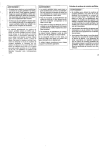
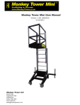
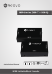
95M-200 GAS-FIRED DIRECT VENT
MODULATING HOT WATER BOILER
HONEYWELL AM (HAM) 0-10VDC MODULE INSTALLATION INSTRUCTIONS
SUPPLEMENTAL INSTRUCTION
(Requires Kit# 550001314)
The Honeywell AM (HAM) kit allows the boiler’s modulation to be controlled by an external 0-10vdc signal
supplied by most modulating multiple boiler controls.
!
WARNING
!
This document must only be used by a qualified heating installer or service technician. Read
all instructions, including this Supplement, the
Boiler Installation Manual (p/n# 240006103), the
Control Manual and Operating Instructions (P/
N# 240006104), and the Parameter Guide (P/N#
240006105), before installing. Perform steps in
the order given. Failure to comply could result
in severe personal injury, death or substantial
property damage.
IMPORTANT: The alarm contacts of the HAM module are rated for 2 amps at 120 vac. All hard lockout
conditions of the boiler control module will cause an
alarm. Soft lockouts will not cause an alarm.
In addition to mounting and wiring the HAM module
to each boiler operated by the multiple boiler controller, you will need to program the boiler control
module of each boiler to accept a 0-10vdc input signal, as described in these instructions.
IMPORTANT: Installation must comply with local requirements and with the National Fuel Gas Code,
ANSI Z223.1 for U.S. installations or CSA B149.1 or
B149.2 for Canadian installations.
P/N 240005544, Rev. 1.1 [04/06]
GAS FIRED DIRECT VENT MODULATING HOT WATER BOILER
HONEYWELL AM (HAM) 0-10VDC MODULE INSTALLATION INSTRUCTIONS
P/N# 240005544, Rev. 1.1 [04/06] • Printed in USA • Made In USA
INSTALLATION PROCEDURE
!
WARNING
!
2. Insert a small flat-blade screwdriver into slot on bottom of HAM Module (at tapered end of module cover)
and gently pry off the cover.
Electrical shock hazard — Turn off power to the
boiler before proceeding with the installation.
Failure to comply could result in severe personal
injury, death, or substantial property damage.
3. With HAM cover removed, carefully insert either end
of the ribbon cable into the HAM plug. Cable will fit into
the cutout on the end of the module cover and base.
(See Figure 1.)
MOUNTING AND WIRING THE HAM MODULE
– KIT COMPONENTS –
•
•
•
4. Route multiple boiler controller wires and alarm wires
through the boiler cable ways, along with the other wiring. Strip ends and attach to the terminals shown in
Figure 2. Use the cable clamp supplied in the HAM kit
to secure the alarm wires to the module.
HAM Module with cable clamp and screws
Ribbon Cable
(2) 6 x ½” Hex Head Screws
– TOOLS REQUIRED –
•
•
•
•
•
0-10vdc signal from multiple
boiler control
(+)
(–)
Phillips-head screwdriver
Flat-head screwdriver
Small flat-head screwdriver
¼” nut driver
Drill and 3/32” drill bit
Ribbon
Cable
Cover
Alarm
Terminals
Ribbon Cable
Figure 2 - HAM Wiring Connections
5. Mount HAM Module to right jacket or surface exteriour of boiler.
6. Fasten HAM cover on the module.
Base and
PC Board
Assembly
7. Plug the end of the ribbon cable into the empty socket on the left end of the boiler control module.
8. Restore power to the boiler.
Figure 1 - HAM Module Assembly
1. Remove boiler front jacket panel by pulling panel
away from boiler.
2
2. Once the instructions for preparation of the boiler are
completed, activate code mode on the boiler control
module as follows:
PROGRAMMING THE BOILER CONTROL MODULE
IMPORTANT: The factory default setting for operation of the boiler control module is for thermostat control. The module must be programmed, as described
in the following, to operate from a 0-10vdc input signal to operate correctly with the AM4 module.
a. Press and hold the “Step” button. Continue holding “Step” and press “Mode” as well. Hold both buttons for 2 seconds or longer. The module readout
will change to [CODE]. Release the “Step” and
“Mode” buttons.
Follow instructions in the “Installation Manual” (P/N#
240006103) and the “Control Manual and Installation
Instructions” (P/N# 240006104) to install, set up and
adjust the boiler.
b. Press “Step” once. The module readout will show
[C - XX], where the “XX” will be a random number.
c. Use “+” or “-” to change the last two digits until the
display shows [C - 05].
DIFFERENCES FROM STANDARD OPERATION
1. The HAM module responds to a signal from the
multiple boiler controller. The boiler will not cycle on
thermostat action, but on the control signal from the
HAM module to the boiler control module. To test boiler
operation, you will need to operate the multiple boiler
controller to signal the boiler to initiate a call for heat to
test the boiler and controls.
NOTE: To change numbers one unit at a time, tap the “+” or “-”
buttons. To make the number change quickly, hold down “+” or
“-” buttons.
d. When the display shows “C - 05”, press “Store” to
enter the code number.
3. Revise parameter 34 as follows:
2. Parameter readouts (Boiler Control Module):
a. Once the code has been stored, change to the
“Parameter” mode by pressing the “Mode” button
until parameter mode is selected.
• Parameter 4 will not show outside temperature.
The boiler control module does not use an outside
sensor when using the HAM module.
b. Press repeatedly until the readout shows [P . 34].
The readout sequence as you press the button will be:
• Parameter 6 will not show target outlet water temperature. Water temperature control is performed
by the multiple boiler controller.
[1 140], [2 .01], [3 .01], [4 190], [P . 05], [P . 06],
[P . 07], etc.
PROGRAMMING THE CONTROL MODULE
FOR HAM INPUT
The readout will continue to show “P . ” followed
by a two digit number that increases each time you
press the “Step” button.
1. You must program the boiler control module to accept the 0-10 vdc input signal from the HAM module as
described on the next page.
!
WARNING
NOTE: The actual parameter values displayed may vary, depending on the application. The parameter sequence will always occur in the order shown.
!
c. When the readout shows [P . 34], stop pushing
the “Step” button. Wait a few seconds and the display will show the current setting for parameter 34 in
the right two display spaces.
Do not attempt to revise any other control settings except those covered in the Boiler Control
Manual (P/N# 240006104) and Parameter Guide
(P/N# 240006105). Perform only the revisions described in this document and the aforementioned
manuals. Failure to comply could result in erratic
or unreliable operation of the boiler.
d. Press the “+” or “-” buttons to change the value
until the display shows [- - 04].
e. Save the change by pressing the “Store” button.
3
1. With the boiler electrical power OFF, unplug one of
the electrical connectors to either the supply or return
temperature sensor.
NOTE: To return the boiler to thermostat operation, perform the
above steps, but set parameter 34 so display shows [- - 00]
instead of [- - 04].
4. Exit code mode by pressing once.
2. Restore power to boiler and allow to cycle.
TEST & VERIFY BOILER/CONTROL OPERATION
3. The boiler control module should enter a hard lockout, causing the HAM alarm relay to close. The remote
alarm should activate.
1. Follow the steps in the “Installation Manual” and “Control Manual and Operating Instructions” to test operation
of the boiler and its controls. To initiate a call for heat
you will have to operate the multiple boiler controller to
activate the boiler.
4. Disconnect boiler power and replace the sensor lead
removed in step 1.
2. Verify the boiler modulates correctly by adjusting the
multiple boiler controller.
5. Restore power and verify boiler operation before
leaving the jobsite.
3. The control response to the 0-10vdc signal will be:
•
•
•
•
REPLACE BOILER COMPONENTS
Boiler on for voltage above 0.5vdc.
Boiler at low fire at voltage between 0.5 and 1.8vdc.
Boiler at high fire at voltage of 10vdc.
Boiler modulates between high fire and low fire for
voltage between 1.8 and 10vdc.
Replace all boiler components and boiler front jacket
panel.
!
WARNING
!
Replace boiler jacket front door after servicing.
The boiler front door must be securely fastened
to the boiler to prevent boiler from drawing air
from inside the boiler room. This is particularly important if the boiler is located in the same
room as other appliances. Failure to keep the
door securely fastened could result in severe
personal injury or death.
TEST HAM ALARM CIRCUIT (IF USED)
IMPORTANT: The HAM will close the alarm relay
contacts on any hard lockout of the boiler control
module. It will not send an alarm on soft lockouts.
4