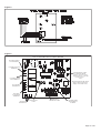
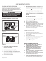
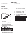
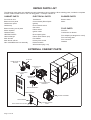
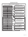
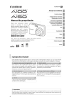
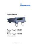
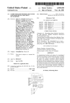
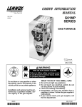
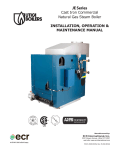
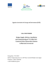
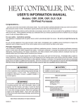
1
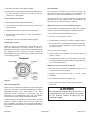
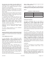
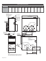
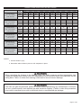
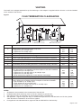
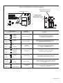
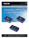
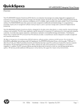
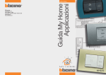
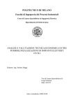
USER’S MANUAL
G34E/G34EV
EXTERNAL SERIES GAS FURNACE
GAS FURNACES – 50 Hz
G34E/G34EV
NOVEMBER 2003
USER’S INFORMATION
MANUAL
**INSTALLER – AFFIX THIS INSTRUCTION
PACKET ADJACENT TO THE FURNACE.
**HOMEOWNER – RETAIN THESE
INSTRUCTIONS FOR FUTURE REFERENCE.
LENNOX HEATING & AIR CONDITIONING - DIVISION OF HEATCRAFT AUSTRALIA PTY LTD
Note: Due to an ongoing commitment to quality and design improvements, specifications, ratings and dimensions are subject to
change without notice and without liability - Heatcraft Australia Pty Ltd, 2003
Owner Record
Furnace Model #
Serial #
Installation Date
INSTALLED BY:
Dealer
Address
Telephone #
Licence #
Contact Person
Other Equipment Installed:
Equipment Type
Installation Date
Model #
Serial #
Equipment Type
Installation Date
Model #
Serial #
Equipment Type
Installation Date
Model #
Serial #
USER’S INFORMATION MANUAL
Gas-Fired Furnace
READ ALL INSTRUCTIONS IN THIS MANUAL AND RETAIN THIS AND ALL ADDITIONAL INSTRUCTIONS FOR FUTURE REFERENCE.
Congratulations...
...you have one of the most modern gas furnaces made. Your unit has been carefully selected to keep you warm and
comfortable during the winter months. It will deliver superb performance with only minimal help from you.
To keep your operating costs low and to eliminate unnecessary service calls, we have provided a few guidelines. These
guidelines will help you understand how your gas furnace operates and how to maintain it so you can get years of safe
and dependable service.
FIRE OR EXPLOSION HAZARD
Failure to follow safety warnings exactly could result in serious injury death or property
damage.
- Do not store or use gasoline or other flammable vapors and liquids in the vicinity of this
or any other appliance.
- What to do if you smell gas:
• Do not try to light any appliance.
• Do not touch any electrical switch; do not use any phone in your building.
• Leave the building immediately.
• Immediately call your gas supplier from a neighbor’s phone. Follow the gas supplier’s
instructions.
• If you cannot reach your gas supplier, call the fire department.
- Installation and service must be performed by a qualified installer, service agency or the
gas supplier.
TABLE OF CONTENTS
SAFETY ...................................................................................................................................................................... 2
OPERATING YOUR FURNACE ................................................................................................................................ 2
Lighting Instructions ...................................................................................................................................................... 2
Temperature Control ...................................................................................................................................................... 3
Fan Operation ................................................................................................................................................................ 3
MAINTENANCE OF YOUR FURNACE ...................................................................................................................... 4
Periodic Inspections ...................................................................................................................................................... 4
Cleaning/Replacing the Filter ........................................................................................................................................ 5
Parts Replacement Guide ............................................................................................................................................ 6
20541401
Issue 0230
Page 1 of 6
For your safety Read before operating
A flood-damaged furnace is extremely dangerous.
Attempts to use the furnace can result in fire or explosion.
A qualified service agency should be contacted to inspect
the furnace and to replace all gas controls, control system
parts, electrical parts that have been wet or the furnace if
deemed necessary.
Here are a few “Do’s and Don’ts”
•
Do become familiar with the instructions.
•
Do check to see that your home has adequate
insulation, weatherstripping, caulking, and storm
windows. Elimination of infiltration of outside air and
drafts can save up to 40% of your fuel bill.
•
Do consider adding a humidifier to your heating
system. Higher indoor humidity slows evaporation of
perspiration, making the home seem warmer.
•
Don’t waste fuel by setting your thermostat too high.
Energy conservation experts recommend a daytime
thermostat setting of 20°C, with a lower setting at
night.
•
•
Do lower the thermostat setting a few degrees if you
expect to be away for more than a day. Your normal
temperature setting can then be restored more
economically.
Don’t turn off the furnace when you expect to be away
for more than a day. Instead, lower the thermostat
setting a few degrees. You can then restore normal
comfort level quickly and save fuel too.
The furnace area must be kept clear and
free of combustible materials, gasoline,
and other flammable vapors and liquids.
Failure to do so could cause actions that
may result in property damage, personal
injury, or loss of life.
Operating Your Furnace
Lighting Instructions
1. STOP! Read the previous safety information.
2. Set the thermostat to the lowest setting.
3. Turn off all electric power to the furnace.
4. Remove the burner compartment access panel.
5. This appliance is equipped with an automatic ignition.
device. Do not try to light the burners by hand.
6. Move the gas control switch to “OFF” (see Figure 1).
Figure 1
Gas Control Diagram
•
Don’t block registers with furniture.
•
Don’t put a lamp, TV, or radio too near your
thermostat. This will cause it to give a false reading.
If you do not follow these instructions
exactly, a fire or explosion may result,
causing property damage, personal injury,
or loss of life.
These furnaces are equipped with an ignition device
which automatically lights the burners. Do not try to light
the burners by hand.
7. Wait 5 minutes to clear out any gas. Then smell for
gas (including at the bottom of the unit near the
ground).
If you smell gas, stop and follow the directions in
“What to do if you smell gas” on page 1. If you
don’t smell gas, continue to next step.
If the switch will not move by hand, don’t try to repair it,
call a qualified service technician. Force or attempted
repair may result in a fire or explosion.
8. Move the gas control switch to “ON”.
Do not use this furnace if any part has been under water.
10.Turn on all electric power to the furnace.
20541401
9. Replace the burner compartment access panel.
Issue 0230
Page 2 of 6
11. Set the thermostat to the desired setting.
Fan Operation
12.If the furnace will not operate, follow the instructions in
“To Turn Off Gas to Furnace” and call your service
technician or gas supplier.
You may wish to increase your comfort by setting your
system for continuous air circulation of the indoor air. The
fan switch on the thermostat permits you to do this.
To Turn Off Gas to Furnace
With the switch in the “ON” position the fan will operate
continuously. “AUTO” position gives fan operation only
when the unit is in either heating or cooling.
1. Set the thermostat to the lowest setting.
2. Turn off all electric power to the furnace if service is to
be performed.
3. Remove the burner compartment access panel.
4. Move the gas control switch to “OFF” (see Figure 1).
Do not force.
5. Replace the burner compartment access panel.
What to do if your unit is not heating properly
If your furnace is operating but fails to provide complete
comfort, check the following before calling for service:
1. Be sure the thermostat setting is correct.
2. Check to see if the filter is clean.
3. Check with the contractor for return air grille locations.
Temperature Control
There are many types and styles of thermostats. Yours
may look different from the one pictured in Figure 2,
depending on the type of thermostat and whether cooling
was installed with the system. However, almost all
thermostats perform the same basic functions described
in the following section.
4. Be sure air can circulate freely throughout your home.
Do not block supply registers or return air grilles with
furniture or rugs.
And if you also have cooling...
5. Keep surface of the outdoor coil free from dirt, lint,
paper, or leaves.
6. Check and clean indoor coil, if necessary. (This check
should be made at the start of each cooling season by
your service technician).
What to do if your unit fails to operate
1. Be sure the main switch that supplies power to the
furnace is in the “ON” position.
2. Replace any burned-out fuses or reset circuit
breakers.
3. Be sure the thermostat is properly set.
Figure 2
4. If the furnace still does not start, call your service
technician.
Thermostat Operation
There are two (2) switches located on the thermostat (see
Figure 2). One switch controls the heating and cooling (if
applicable) functions. The other switch is for “FAN”
operation, either continuous or automatic. On the
thermostat is the temperature range for the heating
temperature and the cooling temperature desired.
Should the gas supply fail to shut off or if
overheating occurs, shut off the gas valve
to the furnace before shutting off the
electrical supply.
To put the system into operation, push the switch to either
“HEAT” or “COOL” position. After you have chosen the
type of operation you desire, move the thermostat dial or
lever to select the temperature you would like the system
to maintain.
20541401
Issue 0230
Page 3 of 6
Maintenance Of Your Furnace
Should you observe unusual amounts of any of the
following conditions, it is important that you call your
authorized dealer at once to obtain a qualified service
Always shut off all power to the unit before
attempting
any
of
the
following
maintenance procedures. Failure to do so
may result in personal injury.
inspection:
• Rust, flakes, or other deposits
• Coatings
There are routine maintenance steps you should take to
keep your furnace operating efficiently. This maintenance
will assure longer life, lower operating costs, and fewer
service calls. In addition to the maintenance procedures
listed in this manual, there are also other service and
maintenance procedures that require the skills of a
service person who has specialized tools and training.
(See “Servicing the Furnace” section of the Installation
and Servicing part of this booklet.) Personal injury can
result if you are not qualified to do this work. Please
call your dealer when service is needed.
• Corrosion
Even if no unusual rust or other conditions are observed,
it is recommended that the furnace be inspected and
serviced at least once per year by a qualified service
technician.
Regular
inspection
and
planned
maintenance will assure many years of economical
performance from your gas furnace.
Combustion Air
Cleaning
Adequate combustion and ventilation air
must reach your gas furnace to provide for
proper and safe operation. Do not block or
obstruct air openings on the furnace, air
openings communicating with the area in
which the furnace is installed and the
spacing around the furnace. Any
obstruction of this airflow can cause an
unsafe condition which may result in death
or permanent injury.
The cabinet of the furnace can be cleaned with soap and
water. Grease spots can be removed with a household
cleaning agent. The cabinet can be kept attractive by
polishing with automotive wax at least twice a year.
Installations Around Insulation
Insulating materials may be combustible. Therefore, a
furnace installed in an attic or other insulated space must
be kept free and clear of insulating materials. Make sure
to examine the furnace area when the furnace is installed
or additional insulation has been added.
Furnaces located in a closet, alcove, or utility room must
have provision for adequate air supply by means of upper
Periodic Inspections
and lower grilles in the door, or by the introduction of
Your gas furnace is designed to give many years of
efficient, satisfactory service. However, the varied air
pollutants commonly found in most areas can affect
longevity and safety. Chemicals contained in everyday
household items such as laundry detergents, cleaning
sprays, hair sprays, deodorizers, and other products
which produce airborne residuals may have an adverse
affect upon the metals used to construct your appliance.
It is important that you conduct periodic physical
inspections of your appliance, paying special attention to
the gas burner and the flue outlet from the furnace.
These components are located at the front of the unit. A
flashlight will be useful for these inspections. Make one
inspection prior to the beginning of the heating season
and another during the middle.
outside air, or both. AGA codes must be adhered to.
Flueing and Furnace Support
Flueing of this furnace must comply with our published
instructions. Be sure the installer has followed these
requirements. If not, you should request the installer to
comply as soon as possible.
For your safety, please note the following:
1. Non-condensing furnaces may be common vented
with another appliance in certain circumstances. Refer
to the installation instructions. Refer to the installation
instructions and AGA 601 code for proper installation
guidelines.
20541401
Issue 0230
Page 4 of 6
The vent from your furnace may rise vertically and
terminate above the roof. When horizontal flueing a noncondensing furnace, an approved flue cowl must be
used. Refer to the installation instructions for further
information on horizontal flueing.
Make sure all flue product carrying areas and materials
external to the furnace (i.e. vent terminals, etc..) are clear
and free of any obstruction, slope upward, and have no
holes or leaks.
Refer to Table 1 when selecting the proper size and
quantity of disposable filter.
If your air distribution system has a central return air
filtergrille, you do not need a filter in your furnace. Clean
the filter-grille the same way permanent filters are cleaned.
Table 1
EXTERNAL FILTER RACK SIZE
Check to see that the furnace cabinet is sound and firmly
supported, without sagging. There should be no cracks or
gaps between the furnace and the base or floor, which
would permit entry of unfiltered air.
It is important that the outside area where the vent
terminates is kept clear of any obstructions which might
block or impede the venting of the furnace. Should
venting become blocked at anytime, your furnace is
equipped with a special safety control to prevent
operation of the furnace until the condition has been
corrected. Contact your dealer if you desire more
information about this safety feature.
Should any unusual conditions be observed during your
inspections, call an authorized service dealer
immediately.
SIDE RETURN
394 X 635
394 X 635
394 X 635
BOTTOM/END RETURN
305 X 635
394 X 635
483 X 635
Note: Filters not supplied
Safety Interlock Switch
The blower compartment door on your furnace is
equipped with a safety interlock switch that will
automatically shut off your complete system (including
blower) once the door is removed. This is for your
personal safety. Be sure to check your furnace for proper
operation once the door or panel has been replaced.
For proper venting terminations, see the Installation
Instructions furnished with the furnace.
If the system does not operate once the panel has been
replaced, try removing and replacing it once again. If the
furnace still does not operate, call your dealer for service.
Return Air
Rollout Switch
Ascertain that all return air duct connections are tight and
sealed to the furnace cabinet and that all return air grilles
or registers are located outside the space containing the
furnace.
This unit is equipped with a manual reset high
temperature sensor or rollout switch. In the unlikely event
of a sustained main burner flame rollout, the rollout switch
will shut off the flow of gas by closing the main gas valve.
The switch is located inside the gas burner area. Flame
rollout can be caused by blockage of the power vent
system, a blocked heat exchanger, or improper gas
pressure or adjustment. If this event occurs, the unit will
not operate properly. The gas supply to the unit should be
shut off and no attempt should be made to place it in
operation. The system should be inspected by a qualified
service technician.
Cleaning/Replacing the Filter
It is very important to clean or replace the air filter
regularly. Dirty filters are the most common cause of
inadequate heating or cooling performance and can
sharply increase the operational costs of your unit. In
some cases, they can double the cost. The air filter
should be inspected at least every 6 weeks and cleaned
or replaced as required.
Your furnace may use either a disposable filter or a
permanent filter. The type of filter may be indicated on a
label attached to the filter. If a disposable filter is used,
replace with the same type and size. If a permanent filter
is used, clean filter and place back in furnace. To clean a
permanent filter, shake filter to remove excess dirt and/or
use a vacuum cleaner. Wash filter in soap or detergent
water and replace after filter is dry. Permanent filters do
not need to be oiled after washing.
Permanent filters may be replaced with disposable filters.
20541401
Lubrication
Lubrication of the bearings in the circulating air blower
motor and the combustion blower motor is not
recommended.
Burner Flame
While the furnace is in operation, observe the mainburner
flames. Compare these observations to Figure 3 to
determine if proper flame adjustment is present. If your
observations indicate improper flame adjustment, call
your authorized service dealer for service.
Issue 0230
Page 5 of 6
Warranty Procedure
When warranty parts are required:
1. Be prepared to furnish the following information:
a. Purchaser’s name
b. Complete model number, serial number, and date
of installation.
c. An accurate description of the problem or
defective parts.
2. Contact your dealer or distributor.
Keep this User’s Information Manual (including
Warranty) and proof of purchase for your records.
Your warranty is determined from your date of
installation. If proof of your date of installation is not
supplied, the warranty will be based on the
manufacture date code.
Figure 3
Do not attempt to adjust flame! Your service
representative will perform this adjustment correctly.
Failure to follow the correct warranty procedure
could result in disallowance of warranty claim.
PARTS REPLACEMENT INFORMATION GUIDE
CASING GROUP
GAS CONTROL
GROUP BLOWER GROUP
Top Panel
Bottom Panel
Cabinet Wrapper Partition
Front Door
Blower Door
Manifold
Burner
Orifice
Gas Control
Sensor
Ignitor
Shield Top & Bottom
Blower Assembly
Blower Housing
Blower Motor
Blower Wheel
Capacitor
Blower Cutoff
Blower Support
ELECTRICAL GROUP
HEAT EXCHANGER
GROUP INDUCER GROUP
Control Box
Limit Switch
Fan Timer Control Board
Rollout Switch
Transformer
Primary Heat Exchanger
Flue Box Inducer
Burner Opening Panel
Burner Inlet Plate
Flue Opening Pane
Pressure Switch
Blower & Motor
Inducer Adapter Plate
TO OBTAIN INFORMATION ON PARTS: Consult your installing dealer or classified section of your local
telephone directory under the “Heating Equipment” or “Air Conditioning Contractors & Systems” headings for dealer listing
or see the first page of the installation instruction section of this manual for the name and address to contact.
Have available the Model No. and Serial No. located on the unit rating label located on the furnace to insure correct
replacement part.
WARNING: Improper installation, adjustment, alteration, service or maintenance can cause personal injury or property
damage. Consult a qualified installer, service agency, or your local gas supplier for information or assistance.
20541401
Issue 0230
Page 6 of 6
G34E/G34EV EXTERNAL
SERIES GAS FURNACES
AFFIX LABEL HERE
INSTALLATION AND SERVICING INSTRUCTIONS
TABLE OF CONTENTS
Safety ........................................................................................1
Electrical....................................................................................8
Furnace Specifications ..............................................................2
Wiring Diagram........................................................................10
Installation Equipment ..............................................................3
Unit Start Up ............................................................................11
Duct System ..............................................................................4
Unit Adjustments ....................................................................13
Installing Optional Cooling Coil ................................................4
Service Procedures ................................................................14
Venting & Flueing ......................................................................5
Parts Listings ..........................................................................16
Setting up Procedures ..............................................................6
Coil Fitting Instructions............................................................18
Gas Piping ................................................................................7
Trouble Shooting ....................................................................19
RETAIN THESE INSTRUCTIONS FOR FUTURE REFERENCE
Do not store or use petrol or other flammable
vapors and liquids in the vicinity of this or any
other appliance.
Installation and service must be performed by a
qualified installer, service agency or the gas
supplier to AGA 601 installation codes.
Installation by an unqualified person may lead to
equipment damage and/or a hazardous condition
which may cause bodily injury and harm and, as
such, at the sole discretion of the manufacturer,
the entire warranty may be voided and be of no
further force and effect.
WHAT TO DO IF YOU SMELL GAS:
• Do not try to light any appliance.
• Extinguish any open flame.
• Do not touch any electrical switch; do not use
any phone in your building.
• Immediately call your gas supplier from a
neighbour’s phone. Follow the gas supplier’s
instructions.
• If you cannot reach your gas supplier, call the
fire department.
Page 1 of 26
SAFETY
The following is a list of safety precautions and their locations in this manual.
These safety rules and precautions must be followed when installing this furnace.
1. Use only with type of gas approved for this furnace. Refer to the furnace rating plate.
2. Install this furnace only in a location and position as specified in The
Location/Placement Section on page 4 of these instructions.
3. Never test for gas leaks with an open flame. Use a commercially available soap
solution made specifically for the detection of leaks to check all connections, as
specified in the Gas Piping section on page 7 of these instructions.
4. Always install furnace to operate within the furnace’s intended temperature-rise
range with a duct system which has an external static pressure within the allowable
range, as specified in Furnace Specifications on page 3 of these instructions. See
furnace rating plate.
5. The furnace is not to be used for temporary heating of buildings or structures under
construction.
Page 2 of 26
G34E/EV FURNACE SPECIFICATIONS
DIMENSIONS mm
MODEL
A
B
C
D
E
F
G
H
I
J
K
G34E/EVQ3-80
443
1023
1345
259
803
259
803
426
–
305
231
G34E/EVQ4-80
443
1023
1345
259
803
259
803
426
–
305
231
G34E/EVQ4-110
529
1060
1485
425
898
308
898
426
444
356
231
G34E/EVQ5-110
529
1060
1485
425
898
308
898
426
444
356
231
G34E/EVQ5-130
529
1060
1502
425
955
357
946
427
451
356
231
OPTIONAL
DUCT FLASHING KIT
FITS EITHER SIDE
PART #700960
FLUE TERMINAL
C
FLUE TERMINAL
REFRIGERATION
ACCESS PLATE
050/080/110/130
& CONDENSATE
DRAIN
CONNECTIONS
150
ACCESS HATCHES
B
H
H
RETURN
AIR
SUPPLY
AIR
I
BACK VIEW
050/080=90
110/130=130
LEFT SIDE (VIEWED FROM FRONT)
FLUE TERMINAL
F
050/080=35
L10/130=45
G
FLUE TERMINAL
REGISTRATION
ACCESS PLATE
L10/L30
& CONDENSATE DRAIN
CONNECTIONS
SERVICE COVER
DUCT CONNECTIONS
ELECTRICAL
INLETS
GAS
CONNECTION
3/4"
J
J
RETURN
AIR
SUPPLY
AIR
K
FRONT VIEW
D
E
NOTE:
DUCT CONNECTIONS AND ACCESS HATCHES
ARE INTERCHANGEABLE FROM SIDE TO SIDE
Page 3 of 26
16
FURNACE BLOWER SPECIFICATIONS AND AIR FLOW DATA
BLOWER SYSTEM
BLOWER
SPEED
0.1 / 25
0.2 / 50
0.3 / 75
EXTERNAL STATIC (IN. W.C.) / pa
0.4 / 100
0.5 / 125
0.6 / 150
0.7 / 175
0.8 / 200
0.9 / 225
1.0 / 250
G34E/EVQ3-50
LOW
390
366
343
320
295
270
241
214
185
157
(254 X 152 WHEEL)
MED
552
529
503
476
448
418
386
353
318
281
(1/3HP MOTOR)
HIGH
698
674
648
619
589
558
525
490
454
416
G34E/EVQ3-80
LOW
390
366
343
320
295
270
241
214
185
157
(254 X 152 WHEEL)
MED
552
529
503
476
448
418
386
353
318
281
(1/3HP MOTOR)
HIGH
698
674
648
619
589
558
525
490
454
416
G34E/EVQ4-80
LOW
612
603
593
582
570
556
541
526
509
491
(305 X 228 WHEEL)
MED
772
764
755
744
733
720
706
691
675
658
(1HP MOTOR)
HIGH
951
931
908
884
857
828
797
764
728
690
G34E/EVQ4-110
LOW
612
603
593
582
570
556
541
526
509
491
(305 X 228 WHEEL)
MED
772
764
755
744
733
720
706
691
675
658
(1HP MOTOR)
HIGH
951
931
908
884
857
828
797
764
728
690
G34E/EVQ5-110
LOW
794
761
725
687
646
604
558
510
459
406
(305 X 305 WHEEL)
MED
982
945
908
875
846
818
794
773
754
738
(1HP MOTOR)
HIGH
1204
1178
1152
1126
1100
1075
1050
1025
1000
976
G34E/EVQ5-130
LOW
794
761
725
687
646
604
558
510
459
406
(305 X 305 WHEEL)
MED
982
945
908
875
846
818
794
773
754
738
(1HP MOTOR)
HIGH
1204
1178
1152
1126
1100
1075
1050
1025
1000
976
NOTES:
1. Air flow values in (L/s).
2. Data taken without filters in place or A/C evaporator in place.
When operating the furnace in the heating mode, the static pressure and the temperature rise
(supply air temperature minus return air temperature) must be within those limits specified on the
rating label. Failure to follow this warning could lead to severe furnace damage.
Turn OFF all gas and electrical power to furnace before performing any maintenance or service
on unit. (Unless specific test requires gas and electrical supplies.) Failure to take this precaution
may result in personal injury due to electrical shock or uncontrolled gas leakage.
Page 4 of 26
SHIPPING AND PACKING LIST
Package 1 of 1 contains:
1 - Assembled unit
1 - Flue adapter/cowl field–installed
2 – Starting collars
The following additional items may be ordered separately, if required:
1 - Cooling coil
1 - Thermostat
1 - LP Changeover kit
Check unit for shipping damage. Receiving party should contact last carrier immediately if any shipping damage is found.
GENERAL
DUCT SYSTEM
These instructions are intended as a general guide and
do not supersede local codes in any way. Consult AGA.
AG-601 INSTALLATION CODE or authorities having
jurisdiction before installation.
The unit is provided with knockouts for either right or
left-side connection of the supply and return air plenums.
Refer to the dimensioned drawing on page 2 to locate
and size the plenum entry into the side of the building.
Cover plates are provided to seal the unused knockouts
and these become convenient access ports for regular
service and maintenance.
The G34E-EV furnace is approved for installation outside
the building only with clearances as listed in figure 1.
Installation of Lennox outdoor central furnaces must be
in accordance with these instructions, local gas fitting
regulations, municipal building codes, electrical wiring
regulations and the current edition of the Australian Gas
Installation Code (AG 601)
The following general recommendations should be
considered when installing the Lennox G34E-EV furnace.
LOCATION / PLACEMENT
The Lennox G34E/EV can be installed in either right or
left hand mode.
NOTE – On some models - 1/3 and 1/2 hp blower
motors are equipped with either four flexible mounting
legs or three flexible legs and one rigid leg. The rigid leg
is equipped with a shipping bolt and a flat white plastic
washer (rather than the rubber mounting grommet used
with a flexible mounting leg). This shipping bolt and flat
washer must be removed before the furnace is put into
operation. Once the shipping bolt and washer are
removed, the rigid leg will not touch the fan housing.
Select a unit location that will allow for required
clearances per local AG 601 codes and in figure 1.
Also consider gas supply connections, electrical supply,
vent termination and installation and service clearances
(600mm. front).
Accessibility and service clearances must not take
precedence over fire protection clearances.
The Lennox G34E-EV furnace should be set on a
field-provided platform to keep the unit base out of
water. The unit is equipped with base rails, which lift the
bottom of the unit off of the platform. Unit must be
leveled using shims or leveling bolts. Knockouts are
provided in unit base to install field-provided leveling bolts.
Page 5 of 26
Size and install supply and return air duct system using
industry-approved standards that result in a quiet and
low-static system with uniform air distribution.
The furnace access panel must always be in place when
the unit is in operation and it must not allow leaks into
the duct system.
Construct a protective covering made of suitable materials
to shield the plenum connections from rain. Rain shield
should be attached to the side of the unit cabinet above
the plenum connections and span the distance to the
building wall above the plenum entry into the structure.
Rain shield connections must be caulked so that they
are weather-tight.
INSTALLING OPTIONAL
COOLING COIL
If optional cooling coil is to be used, install coil
according to the steps indicated below:
1 - Remove G34E-EV unit rear panel (side panel on
G34E-EV130).
NOTE - Installation of larger evaporator coils may
require removal of unit top panel as well.
2 - Place cooling coil on unit coil deck in cooling
compartment.
3 - Using template provided with the coil, cut holes for
refrigeration and drain piping. Align coil with piping
holes in panel. Seal holes around piping.
4 - Reinstall G34E-EV panel.
5 - Make refrigerant piping connections to condensing
unit per local codes and sound plumbing practices.
VENTING
The G34E unit is shipped standard for top flue discharge. A flue adapter is supplied with the furnace. It must be installed
on the outside of the furnace.
Figure 1
FLUE TERMINATION CLEARANCES
a
j
h
j
n
T
c
j
openable
window
e
e
d
h
k
P
door
g
c
I
d
T
b
g
k
T = Flue terminal
I = Mechanical air inlet
Ref.
A
T
M
f
furnace
M = Gas meter
P = Electricity meter or fuse box
Shading Indicates prohibited
areas for flue termination
Minimum clearances mm
Natural draft
Fan assisted
Item
Below eaves, balconies and other projections:
• Appliances up to 50 Mj/h input
• Appliances over 50 Mj/h input
•
300
500
200
300
300
300
500
300
B
From the ground, above a balcony or other surface
C
From a return wall or external corner
D
From a gas meter (M) (see 4.7.11 for vent terminal location of regulator)
1000
1000
E
From an electricity meter or fuse box (P)
500
500
F
From a drain pipe or soil pipe
150
75
G
• or obstruction facing a terminal
From any other flue terminal, cowl, or combustion air intake •
500
500
500
300
500
1500
1500
300
500
1500
1500
H
J
•
Horizontally from any building structure
Horizontally from an openable window, door, non-mechanical air inlet, or
any other opening into abuilding with the exception of sub-floor ventilation:
• Appliances up to 150 Mj/h input
• Appliances over 150 Mj/h input up to 200 Mj/h input
• Appliances over 200 Mj/h input
• All fan-assisted flue appliances, in the direction of discharge
K
From a mechanical air inlet, including a spa blower
1500
1000
N
Vertically below an openable window, non-mechanical air inlet, or any
other opening into a building with the exception of sub-floor ventilation:
• Space heaters up to 50 Mj/h input
• Other appliances up to 50 Mj/h input
• Appliances over 50 Mj/h input and up to 150 Mj/h input
• Appliances over 150Mj/h input
150
500
1000
1500
150
500
1000
1500
• Unless appliance is approved for closer installation
NOTES:
1
2
3
4
5
All distances are measured to the nearest part of the terminal.
Prohibited area below electricity meter or fuse box extends to ground level.
See Clause 5.13.6.6 for restrictions on a flue terminal under a covered area.
See Appendix J, Figures J2(a) and J3(a), for clearances required from a flue terminal to an LP Gas cylinder.
A flue terminal is considered to be a source of ignition.
For appliances not addressed above, approval shall be obtained from the Authority.
Page 6 of 26
GENERAL G34E & EV SERIES
THERMOSTAT INSTALLATION
Install a room thermostat according to the instructions
furnished with it. Select a location on an inside wall and
not subject to drafts, direct sunshine or other heat
sources. The initial heat anticipator setting should be
equal to the total current draw of the control circuit.
Low voltage thermostat connections are to be made as
indicated on the furnace 2 STAGE wiring diagram.
FURNACE CHECK-OUT
Before leaving, the installer should make the
following checks to ensure that the controls are
functioning properly.
CHECKING AND ADJUSTING GAS INPUT
The minimum permissible gas supply pressure for the
purpose of input adjustment is 5 in. W.C. (1.25 kPa) for
natural gas, 11 in. W.C. (2.74 kPa) for propane gas.
GAS PRESSURE REGULATOR
Gas input must never exceed the value shown on the
furnace rating plate. The furnace is equipped for rated
input at manifold pressures of 1.2 in. W.C. (0.30
kPa)–1st stage–and 3.5 in. W.C. (0.87 kPa)–2nd
stage–for natural gas; 3.6 in. W.C. (0.90 kPa)–1st
stage–and 10.0 in. W.C. (2.49 kPa)–2nd stage–for
propane gas.
The manifold pressure can be measured by connecting
a water manometer or gauge to the pressure tap in the
downstream side of the gas valve.
Only small variations in gas input may be made by
adjusting the regulator. In no case should the final
manifold pressure vary more than 0.3 in. W.C. (0.07
kPa) from the above specified pressures.
Page 7 of 26
2-STAGE-SET-UP
Turn the gas valve ON. To adjust the regulator, turn the
adjusting screw on the regulator clockwise to increase
pressure and input;
Counter-clockwise to decrease pressure and input.
There are separate adjusting screws for 1st stage
(marked “LO”, on top of solenoid coil) and 2nd stage
(marked “HI”, on outlet end of valve). NOTE: The
pressure regulator adjustment is sensitive; one turn of
the adjusting screw will result in a relatively large
change in manifold pressure.
If adjustments are being made for propane gas,
follow this procedure:
1. Adjust high fire setting by turning hex adjustment
screw full clockwise.
2. Set low fire setting by turning the low fire adjustment
screw clockwise (located on top of 2nd stage coil) to
desired rate.
3. Set high fire setting by turning the high fire
adjustment screw counter-clockwise to 10.0 in. W.C.
(2.49 kPa) manifold pressure.
Important: Make sure the final high and low fire
manifold pressures are within the allowable ranges
specified above for the gas being used.
Check the furnace rate by observing the gas meter,
when available, making sure all other gas appliances
are turned off. The test hand on the meter should be
timed for at least one revolution.
TEMPERATURE RISE
Check the temperature rise and, if necessary, adjust
blower speed to maintain temperature rise within the
range shown on the unit rating plate.
GAS PIPING
GAS SUPPLY
LEAK CHECK
This unit is to be installed by a licensed gas
plumber fully in accordance with AG601 installation
regulations.
After gas piping has been completed, carefully check all
piping connections (factory and field) for gas leaks. Use
a leak detecting solution or other preferred means.
1 - This unit is shipped standard for centre installation of
gas piping. Piping can be converted for right-side
connection. Simply connect gas supply to piping
assembly.
2 - When connecting gas supply, factors such as length
of run, number of fittings and furnace rating must be
considered to avoid excessive pressure drop. Unit
connection at gas manifold is 1/2 in. (12mm). Size
piping according to gas regulations.
3 - Gas piping must not run in or through air ducts,
clothes chutes, chimneys or gas vents, dumb waiters
or elevator shafts.
4 - Piping should be sloped 6mm per 380mm upward
toward the meter from the furnace. The piping must
be supported at proper intervals (2M) using suitable
hangers or straps
5 - In some localities, codes may require installation of a
manual main shut-off valve and union (furnished by
installer) external to the unit. Union must be of the
ground joint type.
IMPORTANT
Compounds used on threaded joints of gas
piping must be resistant to the actions of
liquified petroleum gases.
Some soaps used for leak detection are
corrosive to certain metals. Carefully rinse piping
thoroughly after leak test has been completed.
Do not use matches, candles, flame or other
sources of ignition to check for gas leaks.
The furnace must be isolated from the gas supply
system by closing its individual manual shut-off valve
during any pressure testing of the gas supply system at
pressures equal to or less than 1/2 psig (3.48 kPa).
IMPORTANT
When testing pressure of gas lines, gas valve
must be disconnected and isolated. See figure
4. Gas valves can be damaged if subjected to
more than 1/2 psig (3.48 kPa).
MANUAL MAIN
SHUT-OFF VALVE
WILL NOT HOLD
NORMAL TEST
PRESSURE
GAS VALVE
FURNACE
CAP
NOTE-Installer must provide a 1/8 in. (3 mm) N.P.T.
plugged tap in the field piping upstream of the gas
supply connection to the unit. Tap must be accessible
for test gauge connection. This requirement is negated
if the gas valve in the unit is fitted with an integral
pressure tapping point.
Figure 4
NOTE-If emergency shutoff is required, shut off main
manual gas valve and disconnect main power to unit.
These devices should be properly labelled by the
installer.
Page 8 of 26
ELECTRICAL
ELECTROSTATIC DISCHARGE (ESD)
6-
Complete wiring connections to equipment using
wiring diagrams provided with unit and in field
wiring diagrams shown in figures 5. Use 18 gauge
wire or larger for thermostat connections.
7-
Electrically ground unit in accordance with local
codes.
8-
Three 240 volt accessory terminals are provided on
the control board. Two are energized with the
indoor blower and one is energized with the
combustion air blower. Any accessory rated up to
one amp can be connected to the accessory
terminals with the neutral leg of the circuit
connected to the 240 volt neutral wires.
9-
This unit is equipped with an integrated control
board that controls blower operation, fan off timings
(EGC Board 0nly) and ignition. The board includes
a terminal strip for thermostat connections and two
diagnostic LEDs. See figure 6 for control board
configuration. Diagnostic codes are given in a chart
at the back of this manual.
Precautions and Procedures
Electrostatic discharge can affect electronic
components. Take precautions during furnace
installation and service to protect the furnace’s
electronic controls. Precautions will help to
avoid control exposure to electrostatic
discharge by putting the furnace, the control
and the technician at the same electrostatic
potential. Neutralize electrostatic charge by
touching hand and all tools on an unpainted
unit surface, such as the gas valve or blower
deck, before performing any service procedure.
These units operate on 240 volt, single phase, 50 Hz
electrical power. Refer to figure 5 for field wiring and
figure 7 for schematic wiring diagram and
troubleshooting.
1-
Select circuit protection and wire size according to
requirements listed on unit rating plate.
2-
Snap-hole plugs are provided on both sides of
cabinet to facilitate wiring.
3-
Install room thermostat according to instructions
provided with thermostat.
4-
Install a separate disconnect switch (protected by
either fuse or circuit breaker) near the unit so
power can be turned off for servicing.
5-
Before connecting thermostat or power wiring,
check to make sure wires will be long enough to
facilitate servicing at a later date. Remove blower
access panel and swing panel to check wire length
for access.
Page 9 of 26
The red diagnostic button can be used to view the
last failure code. (EGC Ignition Board Only)
10 - Refer to blower speed chart on wiring diagrams for
factory set cooling, heating and continuous fan
speeds. Systems using a cooling thermostat subbase may operate the blower continuously (factory
set at low speed) through the thermostat “FAN ON”
switch. Systems, which do not include a cooling
sub-base require a toggle switch which must be
wired between terminals “R” and “G” on the
thermostat connection terminal strip. The blower
motor will operate at the designated speed during
cooling or heating demand; however, when
demand is satisfied, blower speed will revert to
selected continuous speed.
Figure 5
Figure 6
EGC-3A INTEGRATED CONTROL BOARD
HEATING SPEED
TAP TERMINAL
CONTINUOUS FAN
TERMINAL
GND
DIAGNOSTIC CODE
ERASE JUMPER
(Remove power to control
and short pins for 10 seconds
to erase previous
code.)
COOLING SPEED
TAP TERMINAL
ACCESSORY
TERMINALS
RED DIAGNOSTIC BUTTON
(Depress button and hold for
display of last failure code.)
L1
HEATING
ACCESSORY
TERMINAL
NEUTRAL
TERMINALS
DIAGNOSTIC
LEDS
THERMOSTAT
TERMINAL STRIP
BLOWER TIME
ADJUSTMENT
JUMPER
Page 10 of 26
Figure 7 (EGC-3 Ignition Module)
KEY
COMPONENT
P
AL
ROS
P1
P2
CMB
W2
BI
CU
T1
F
X
PRESSURE SWITCH
AUX LIMIT PRESSURE SWITCH
AUX LIMIT
ROLL–OUT SWITCH
ROLL–OUT SWITCH
PLUG 6 PIN PLUG 6 PIN
SPADE CONNECTORS
SPADE CONNECTORS
COMBUSTIONCOMBUSTION
BLOWER BLOWER
2ND STAGE HEAT
TERMINAL
2ND STAGE
HEAT TERMINAL
BLOWER INTERLOCK
BLOWER INTERLOCK
CONDENSING
UNIT
CONDENSING UNIT
TRANSFORMER
TRANSFORMER
LOW VOLAGE FUSE
LOW VOLAGEMANUAL
FUSE RESET
MANUAL RESET
IGN BOARD
COMPONENT
OR
F 5A
240V
T1 24V
4 P1
P
R OS
P2 G
5
OR
AL
BK
OR
AL
P2 W
P1
(1,2)
8
P2 Y
1 P1
P2 C
L
WH
X
X
9 P1
SPARK
ELECTRODE
GAS VALVE
FLAME
FLAME SENSOR
M
C
3 PIN PLUG
AND CORD
BR
BR
RD
RD
3 P1
4 P1
GND
A
N
24VAC
WH
N
E
TO
CONDENSOR
HUM
BI
L1 240V
24V TO THERMOSTAT C
MAY NOT BE REQUIRED
P2 R
24 VAC
CMB
BLWR HUM
GND
E
L1
ACC ACC
1
L1
WH
ACB
COOL
ACB
LO
ACB
HEAT
2
BK
BLACK
RED
FAULT CODES
LED
FAULT CODES
4 FLASHES
5 FLASHES
BK
BL
BR
BLUE
INDUCER
INDUBLOWER
BLOW
OFF
NO POWER
STEADY OFF
NOEAT
POWER NORMAL OPERATION
EARTBEAT
CALL FOR HEAT
HEARTBEAT
NORMAL
OPERATION
ES FOR HEAT
GAS VALVE LOCKOUT
FAST HEARTBEAT CALL
ESVALVE LOCKOUT
PRESSURE SWITCH
2 FLASHES
GAS
3 FLASHES
PRESSURE CLOSED
SWITCHOR OPEN
ES
HIGH LIMIT OPEN
CLOSED
OR
OPENSENSE WITH
ES
FLAME
BRN CAP
INDOOR
BLOWER
MOTOR
BRN
WH
HIGH LIMIT OPEN
FLAME SENSE WITH
GAS VALVE OFF
BLACK
BLUE
BROWN
GR
OR
RD
GREEN
ORANGE
RED
VI
WH
YL
VIOLET
WHITE
YELLOW
Figure 8 (U.T. Ignition Module)
IGN BOARD
KEY
COMPONENT
24 VAC
P
AL
ROS
P1
P2
CMB
W2
BI
CU
T1
F
X
PRESSURE SWITCH
AUX LIMIT
ROLL–OUT SWITCH
PLUG 6 PIN
SPADE CONNECTORS
COMBUSTION BLOWER
2ND STAGE HEAT TERMINAL
BLOWER INTERLOCK
CONDENSING UNIT
TRANSFORMER
LOW VOLAGE FUSE
MANUAL RESET
N
E
AL
BK
P
2 P1
R OS
(1,2)
1 P1
L
WH
P
M
C
Page 11 of 26
W2
3 P1
RD
4 P1
TO
CONDENSOR
HUM
BI
GND
A
N
E
24VAC
WH
701081 /
CMB
BLWR HUM
GND
ACC ACC
1
L1
COOL
UNUSED HEAT
FAULT CODES
NO POWER
NORMAL OPERATION
CALL FOR HEAT
GAS VALVE LOCKOUT
PRESSURE SWITCH
CLOSED OR OPEN
HIGH LIMIT OPEN
FLAME SENSE WITH
GAS VALVE OFF
C
W2
7
B
2
BK
BLACK
RED
4 FLASHES
5 FLASHES
P2 C
FLAME
FLAME SENSOR
WH
STEADY OFF
HEARTBEAT
FAST HEARTBEAT
2 FLASHES
3 FLASHES
P2 W
SPARK
ELECTRODE
BR
L1
LED
P2 G
6 P1
700994 – 2R05665
GAS VALVE
2 STAGE
H1
24V TO THERMOSTAT C
MAY NOT BE REQUIRED
P2 Y
240V
T1
24V
3 PIN PLUG
AND CORD
L1 240V
5 P1
F 5A
P2 R
5
W2 RELAY
C
6
BLUE
INDUCER
BLOWER
3
INDOOR
BLOWER
MOTOR
WH
NO
4
BRN CAP
1
BRN
NC
2
Figure 9 (U.T. Ignition Module)
IGN BOARD
KEY
COMPONENT
24 VAC
P
AL
ROS
P1
P2
CMB
W2
BI
CU
T1
F
X
PRESSURE SWITCH
AUX LIMIT
ROLL–OUT SWITCH
PLUG 6 PIN
SPADE CONNECTORS
COMBUSTION BLOWER
2ND STAGE HEAT TERMINAL
BLOWER INTERLOCK
CONDENSING UNIT
TRANSFORMER
LOW VOLAGE FUSE
MANUAL RESET
N
E
AL
P
5
P1
T1
240V
24V
BK
R OS
(1,2)
P
M
H1
C
P2 W
P2 Y
1 P1
P2 C
9 P1
W2
SPARK
ELECTRODE
FLAME
FLAME SENSOR
BR
3 P1
RD
4 P1
TO
CONDENSOR
HUM
BI
GND
A
N
WH
E
GND
24VAC
701081 /
CMB
BLWR HUM
L1
ACC ACC
1
L1
ACB
COOL
ACB
LO
FAULT CODES
STEADY OFF
HEARTBEAT
FAST HEARTBEAT
2 FLASHES
3 FLASHES
NO POWER
NORMAL OPERATION
CALL FOR HEAT
GAS VALVE LOCKOUT
PRESSURE SWITCH
CLOSED OR OPEN
HIGH LIMIT OPEN
FLAME SENSE WITH
GAS VALVE OFF
C
W2
7
B
2
BLACK
RED
LED
ACB
HEAT
BK
WH
4 FLASHES
5 FLASHES
24V TO THERMOSTAT C
MAY NOT BE REQUIRED
P2 G
8
L
WH
700994 – 2R05665
GAS VALVE
2 STAGE
3 PIN PLUG
AND CORD
L1 240V
4 P1
F 5A
P2 R
5
W2 RELAY
C
6
BLUE
INDUCER
BLOWER
3
INDOOR
BLOWER
MOTOR
NO
4
BRN CAP
1
NC
2
BRN
WH
UNIT START-UP
FOR YOUR SAFETY READ BEFORE LIGHTING
Do not use this furnace if any part has been
underwater. Immediately call a qualified service
technician to inspect the furnace and to replace
any part of the control system and any gas
control which has been under water.
If overheating occurs or if gas supply fails to
shut off, shut off the manual gas valve to the
appliance before shutting off electrical supply.
Before attempting to perform any service or
maintenance, turn the electrical power to unit
OFF at disconnect switch.
BEFORE LIGHTING smell all around the appliance area
for gas. Be sure to smell next to the floor because some
gas is heavier than air and will settle on the floor.
Use only your hand to turn the gas control knob.
Never use tools. If the knob will not turn by hand,
do not try to repair it, call a qualified service technician.
Force or attempted repair may result in a fire or
explosion.
Page 12 of 26
UNIT START-UP (CONT.)
PLACING UNIT INTO OPERATION
6-
White Rodgers 36E Gas Valve - Turn knob on gas
valve 180˚ either way to OFF. See figure 8.
Honeywell VR8205 Gas Valve - Turn knob on gas
valve clockwise
to OFF. Do not force. See figure
9.
7-
Wait five (5) minutes to clear out any gas. If you
then smell gas, STOP! Immediately call your gas
supplier from a neighbour’s phone. Follow the gas
supplier’s instructions. If you do not smell gas go to
next step.
8-
White Rodgers 36E Gas Valve - Turn knob on gas
valve 180˚ either way to ON.
G34E/EV units are equipped with a direct spark ignition
system. Do not attempt to manually light burners on
these furnaces. Each time thermostat calls for heat, the
burners will automatically light.
If you do not follow these instructions exactly,
a fire or explosion may result causing property
damage, personal injury or loss of life.
Honeywell VR8205 Gas Valve - Turn knob on gas
valve counterclockwise
to ON. Do not force.
GAS VALVE OPERATION (Figures 8 and 9)
9WHITE RODGERS 36E SERIES GAS VALVE
MANIFOLD
PRESSURE
ADJUSTMENT
SCREW
MANIFOLD
PRESSURE
OUTLET
NO
Replace the access panel.
10 - Turn on all electrical power to unit.
11 - Set the thermostat to desired setting.
NOTE-When unit is initially started, steps 1 through
11 may need to be repeated to purge air from gas line.
12 - If the appliance will not operate, follow the
instructions “Turning Off Gas To Unit” and call your
service technician or gas supplier.
OFF
GAS VALVE SHOWN IN OFF POSITION
TURNING OFF GAS TO UNIT
Figure 10
HONEYWELL VR8205 SERIES GAS VALVE
MANIFOLD
PRESSURE
ADJUSTMENT
SCREW
MANIFOLD
PRESSURE
OUTLET
ON
1-
Set the thermostat to the lowest setting.
2-
Turn off all electrical power to the unit if service is
to be performed.
3-
Remove the access panel.
4-
Turn knob on White Rodgers gas valve 180˚ either
way to OFF; turn knob on Honeywell valve
clockwise
to OFF. Do not force.
5-
Replace the access panel.
OFF
GAS VALVE SHOWN IN OFF POSITION
HEATING SEQUENCE OF OPERATION
Figure 11
1 - When thermostat calls for heat, combustion air
blower starts after a 5 second delay.
1-
STOP! Read the safety information at the
beginning of this section.
2-
Set the thermostat to lowest setting.
2 - Combustion air pressure switch proves blower
operation, and then allows power to ignition
control. Switch is factory set and requires no
adjustment.
3-
Turn off all electrical power to the unit.
4-
This furnace is equipped with an ignition device,
which automatically lights the burners. Do not try to
light the burners by hand.
5-
Remove the access panel.
Page 13 of 26
3 - After 15-second prepurge, spark igniter energizes
and gas valve solenoid valves open.
4 - Spark ignites gas, ignition sensor proves the flame
and combustion process continues.
5 - If flame is not detected after first ignition trial,
ignition control will repeat steps 3 and 4 four more
times before locking out. To re–establish ignition
UNIT ADJUSTMENTS
PRIMARY LIMIT
GAS PRESSURE
The primary limit is located on the heating compartment
vestibule panel. This limit is factory set and does not
require field adjustment.
1-
Check gas line pressure with unit firing at
maximum rate. A minimum of 1.13 kPa for natural
gas or 2.75 kPa for LP/propane gas should be
maintained.
FLAME ROLLOUT SWITCHES (TWO)
2-
After line pressure has been checked and
adjusted, check regulator pressure. Refer to the
unit rating plate for manifold pressure settings. See
figures 8 and 9 for manifold pressure adjustment
screw location. A natural gas to LP/propane gas
changeover kit is required to convert unit.
These manually reset switches are located just above
the burner box. If tripped, a check for adequate
combustion air should be made before resetting.
COMBUSTION AIR PRESSURE SWITCH
The combustion air pressure switch is located on the
heating compartment vestibule panel. This switch
checks for proper combustion air blower operation
before allowing ignition trial. The switch is factory set
and requires no field adjustment.
The fan control is part of the control board located on
the heating compartment vestibule panel. The preset fan
on delay time of 45 seconds is not adjustable. The fan
off delay time is factory adjusted at 120 seconds and
can be adjusted by moving the jumper on the integrated
control board. See figure 10 for settings. EGC board only.
FAN-OFF TIME
To adjust fan-off
Remove timing jumper and select
one of the other pin combinations
to achieve desired time.
12
0
18
0
9
0
6
0
Figure 12
Check temperature rise and, if necessary, adjust blower
speed to maintain temperature rise within range shown
on unit rating plate.
THERMOSTAT HEAT ANTICIPATION
FAN TIMER CONTROL
TIMING
JUMPER
TEMPERATURE RISE
TIMING PINS
(seconds)
Set thermostat heat anticipation to:
0.50 amps
White Rodgers gas valves
0.70 amps
Honeywell gas valves
ELECTRICAL
1-
Check all wiring for loose connections.
2-
Check for correct voltage at unit (unit operating).
3-
Check amp draw on blower motor.
Motor Nameplate________________Actual_________
BLOWER SPEEDS
Note – CFM/Ls readings are taken external to unit with
a dry evaporator coil and without accessories.
Note:- (EGC Ignition Board Only)
1-
Turn off electrical power to furnace.
GAS FLOW
2-
To check for proper gas flow to combustion chamber,
determine Btu input from appliance rating plate. Divide
this input rating by the Btu per cubic foot of available
gas. Result is the required number of cubic ft. per hour.
Determine the flow of gas through gas meter for two
minutes and multiply by 30 to get the hourly flow of gas.
Disconnect existing speed tap at control board
speed terminal.
NOTE - TERMINATION OF ANY UNUSED
MOTOR LEADS MUST BE INSULATED.
3-
Refer to blower speed selection chart on unit wiring
diagram for desired heating or cooling speed.
4-
Connect selected speed tap at control board speed
terminal.
5-
Turn on electrical power to furnace.
Page 14 of 26
UNIT ADJUSTMENTS (CONT.)
FLUE
FAILURE TO OPERATE
1-
If unit fails to operate check the following:
Check flue termination and all connections for
tightness and to make sure there is no blockage.
2 - Check unit for proper draft.
1 - Is thermostat calling for heat?
2 - Is main disconnecting switch closed?
3 - Is pressure switch closed? Obstructed flue will
cause unit to shut off at pressure switch. Check
flue and outlet for blockages.
3 - Is there a blown fuse or tripped circuit breaker?
4 - Reset manual flame rollout switches on burner box
cover.
4 - Is filter dirty or plugged? Dirty or plugged filters will
cause unit to go off on limit control.
5 - Is gas turned on at meter?
6 - Is manual main shut-off valve open?
BURNER FLAME ADJUSTMENT
7 - Is internal manual shut-off valve open?
The G34E/EV burner flame is not adjustable; however,
the flame should be inspected at the beginning of each
heating season and burners should be cleaned, if
necessary. Burner flame should be blue when burning
natural gas, blue/yellow when burning propane gas.
8 - Is unit ignition system in lock out? If unit locks out
again, call serviceman to inspect unit for
blockages.
BURNER FLAME
FLAME
FLAME APPEARS BLUE IF
BURNING NAT. GAS; BLUE/
YELLOW FOR PROPANE.
BURNER
HEAT
EXCHANGER
TUBE
VEST
PANEL
Figure 13
SERVICE
B - BLOWERS
Disconnect power before servicing unit.
Check and clean blower wheels for any debris. Blower
motors are prelubricated for extended bearing life. No
further lubrication is needed.
At the beginning of each heating season, the system
should be checked as follows:
A - ELECTRICAL
1-
Check all wiring for loose connections.
2-
Check for correct voltage at unit (unit operating).
3-
Check amp draw on blower motor.
Motor Nameplate__________Actual__________
Page 15 of 26
The blower access panel must be securely in
place when the blower and burners are
operating. Gas fumes, which could contain
carbon monoxide, can be drawn into living
space resulting in personal injury or death.
SERVICE (CONT.)
C - FLUE TERMINATION
HEAT EXCHANGER
Check flue termination for tightness and to make sure
there is no blockage.
Periodically inspect heat exchanger passages and flue
box for corrosion. If necessary, clean as outlined below:
1-
Turn off the electrical power and gas supply to the
furnace.
2-
Disconnect the wiring to the combustion air fan.
3-
Remove the screws securing the flue box to the
furnace. Clean the flue box with a wire brush
(brass–bristle brush recommended).
4-
Disconnect the gas supply piping and the igniter
and sensor wires. Remove the burner assembly
from the furnace.
5-
Reinstall the flue box using a new gasket.
6-
Reconnect the combustion air fan wiring.
7-
Reinstall the burner box, igniter and sensor wires
and the gas supply piping.
8-
Carefully check all piping connections (factory and
field) for gas leaks. Use a leak detecting solution or
other preferred means.
D - BURNERS
Burners and burner flame should be inspected at the
beginning of each heating season. Clean burners, if
necessary, as indicated below:
1-
Turn off electrical and gas supply to unit.
2-
Disconnect gas supply piping and remove gas
manifold.
3-
Disconnect igniter and flame sensor leads.
4-
Remove burner tray and burners.
5-
Clean the inside of each burner with a bottle brush
as shown figure 12.
Cleaning Burners
BURNER
BOTTLE
BRUSH
IMPORTANT
Some soaps used for leak detection are corrosive
to certain metals. Carefully rinse piping
thoroughly after leak test has been completed.
Do not use matches, candles, flame or other
sources of ignition to check for gas leaks.
Figure 14
6 - Replace burners and burner tray, making sure
burners are properly seated in slots on tray and
orifice in manifold.
7 - Check electrode gap using appropriately sized twist
drills or feeler gauges. Gap should be between
0.110 and 0.140 inches (2.79 to 3.56mm).
9-
Restore electrical power and gas supply. Follow
lighting instructions on front of unit. Check burner
flame and adjust if necessary.
8 - Reinstall burner box and gas supply piping.
Reconnect igniter and flame sensor leads.
9 - Carefully check all piping connections (factory and
field) for gas leaks. Use a leak detecting solution or
other preferred means.
IMPORTANT
Some soaps used for leak detection are corrosive
to certain metals. Carefully rinse piping
thoroughly after leak test has been completed.
Do not use matches, candles, flame or other
sources of ignition to check for gas leaks.
10 - Restore electrical power and gas supply. Follow
lighting instructions on front of unit. Check burner
flame and adjust if necessary.
Page 16 of 26
REPAIR PARTS LIST
The following repair parts are available through independent Lennox dealers. When ordering parts, include the complete
furnace model number listed on the unit rating plate — Example: G24E3-75.
CABINET PARTS
ELECTRICAL PARTS
BLOWER PARTS
Front louver door
Blower access panel
Cabinet rear panel
Cabinet top
Blower housing cut-off plate
Motor capacitor
Cabinet bottom
HEATING PARTS
Heat exchanger
Main burners
Main burner orifices
Gas manifold/Burner box assembly
Transformer
Control board (Direct Spark
Ignition)
Door interlock switch
Gas valve
Flame sensor
Ignition cable
Direct spark igniter
Flame rollout switch (two)
Flue baffles
Primary limit control
Pressure switch
Wire harness plug / cap
Blower wheel
Motor
FLUE PARTS
Flue box
Combustion air blower
Flue adapter (rectangular to round)
Flue mounting plate
Flue connector
Gaskets
EXTERNAL CABINET PARTS
FLUE BOX
COMBUSTION AIR
BLOWER
COIL DECK
FLUE BAFFLES
(75 only)
FRONT LOUVERED
PANEL
PRESSURE
SWITCH
HEAT EXCHANGER
ASSEMBLY
BURNER ASSEMBLY
CONTROL BOARD
BLOWER ASSEMBLY
TRANSFORMER
DOOR INTERLOCK SWITCH
Page 17 of 26
BLOWER ACCESS
PANEL
IN ROOF VENTILATION KIT
G34E-EV
KIT MODEL #
080
701115
110/130
701116
INSTALLATION PROCEDURE
1.
Remove furnace access door.
2.
Remove 2-rainshields from back of door. Attach
appropriate new wiring diagram and lighting
instructions.
3.
Remove 2-rainshields from side of furnace as
shown below.
4.
Remove existing weatherproof lid and discard.
5.
Replace lid with New vented lid supplied. Be sure
to peel off plastic coating if present.
6.
Replace modified door. If cooling coil is fitted a safety
drain is recommended under the entire unit drained
to a safe location, especially in ceiling applications.
This optional part must be ordered separately.
KIT CONTENTS
New lid Old Model
New lid New Model
801003SO
801003SN
801103SO
801103SN
New wiring diagram
G34E
532889W
G34EV
AUS71A
G34
532909W
532889W
AUS71A
532909W
New lighting instructions
G34
42J88
G34
58K8001
Modification Sticker 701121
42J88
58K8001
701121
OPTIONAL PART
Drain tray
701118
701119
APPLICATION
This kit is for applications where a G34E/G34EV
External weatherproof furnace is to be installed
internally in a roofspace, plantroom or other internal
location.
This kit must be installed to prevent overheating of
components due to high ambient environments.
Page 18 of 26
COIL FITTING INSTRUCTIONS
Page 19 of 26
TROUBLESHOOTING
HEATING SEQUENCE OF OPERATION
ABNORMAL HEATING MODE
NORMAL HEATING MODE
GAS VALVE OFF. COMB. BLOWER ON. INDOOR
BLOWER ON HEAT SPEED. SEQUENCE HOLDS
UNTIL NO FLAME SENSED OR MAIN POWER IS
INTERRUPTED AND RESET. DIAG. CODE: 1- FLASHING;
2- OFF (FLAME SENSED WITHOUT VALVE ENERGIZED)
CONTROL MAIN POWER "ON"
FLAME OFF?
YES
CONTROL SELF-CHECK OKAY?
YES
ROLL-OUT SWITCH CLOSED
NO
NO
GAS VALVE, COMB. BLOWER AND INDOOR BLOWER
(WITH DELAY) OFF. REMOVE POWER TO RESET
CONTROL. DIAG. CODE: BOTH ON (CONTROL
SELF-CHECK FAILURE OR INCORRECT WIRING)
NO
YES
LED: SLOW FLASH RATE
GAS VALVE, COMB. BLOWER AND INDOOR BLOWER
(WITH DELAY) OFF. SEQUENCE HOLDS UNTIL
ROLL-OUT SWITCH IS MANUALLY CLOSED.
DIAG. CODE: 1-ON ;
2-FLASHING (FLAME ROLL-OUT OPEN)
THERMOSTAT CALLS FOR HEAT
LED: FAST FLASH RATE
NO
COMB. AIR BLOWER PRESSURE SWITCH OPEN?
YES
GAS VALVE, COMB. BLOWER AND INDOOR BLOWER
(WITH DELAY) OFF. SEQUENCE HOLDS UNTIL
PRESSURE SWITCH CLOSES OR THERMOSTAT
RESETS CONTROL. DIAG. CODE: 1-OFF ;
2-FLASHING ( C.A.B. PRESSURE SWITCH OPEN)
COMBUSTION AIR BLOWER ON?
YES
PRESSURE SWITCH CLOSED WITHIN 2.5 MIN.?
YES
NO
YES
PRESSURE SWITCH WATCHGUARD CONDITION:
GAS VALVE, COMB. BLOWER AND INDOOR BLOWER
(WITH DELAY) OFF. DIAG. CODE: 1-OFF /
2-FLASHING ( C.A.B. PRESSURE SWITCH OPEN) IS 5
MINUTE RESET PERIOD COMPLETE?
COMB. AIR BLOWER PREPURGE (15 seconds)
IGNITION TRIAL (7 seconds) -- START IGNITION
SPARK, OPEN MAIN GAS VALVE.
HAS FLAME REGISTERED WITHIN 10 SECONDS
AFTER IGNITION TRIAL?
YES
IS FLAME SENSED AFTER 10 SECOND
FLAME RECTIFICATION PERIOD?
NO
NO
YES
GAS VALVE OFF. COMB. BLOWER ON. INDOOR
BLOWER (WITH 45 DELAY) ON. HAS CONTROL
FAILED FLAME SENSE 5 TIMES CONSECUTIVELY
DURING ONE HEAT DEMAND?
IF YES, SYSTEM GOES INTO A HARD LOCKOUT.
REMOVE POWER TO RESET CONTROL.
DIAG. CODE: 1-ALT. FLASHING / 2-ALT. FLASHING
IF NO, GO TO "COMB. AIR BLOWER ON?"
INDOOR AIR BLOWER ON 45 SECS AFTER
GAS VALVE IS ENERGIZED
PRIMARY/SECONDARY LIMITS MONITORED
IN HEAT CYCLE. ARE SWITCHES CLOSED?
YES
PRESSURE SWITCH CLOSED?
NO
NO
GAS VALVE OFF. COMB. BLOWER OFF. INDOOR
BLOWER ON UNTIL LIMIT CLOSES. DIAG.
CODE: 1-FLASHING / 2-ON (LIMIT OPEN)
IS LIMIT NOW CLOSED?
YES
YES
THERMOSTAT OPENS
LED: SLOW FLASH RATE
COMB. AIR BLOWER OFF ( 5 sec. delay)
INDOOR AIR BLOWER OFF
(After selected 60, 90, 120, or 180 delay)?
HAS PRIMARY LIMIT OPENED 5 TIMES DURING
ONE UNSATISFIED HEAT DEMAND. IF YES,
SYSTEM GOES INTO 60 MIN.WATCHGUARD.
DIAG. CODE: 1-FLASHING / 2-ON
IF NO, GO TO "COMB. AIR BLOWER ON?"
GAS VALVE, COMB. BLOWER AND INDOOR BLOWER
(WITH DELAY) OFF. DIAG. CODE: 1-OFF / 2-FLASHING NO
(C.A.B. PRESSURE SWITCH OPEN) HAS C.A.B.
PRESSURE SWITCH CLOSED IN 2.5 MINUTES?
YES
Page 20 of 26
COOLING SEQUENCE OF OPERATION
ABNORMAL COOLING MODE
NORMAL COOLING MODE
POWER ON
IGNITION CONTROL MAIN POWER ON.
CONTROL SELF DIAGNOSTIC CHECK.
IS CONTROL OPERATING NORMALLY?
NO
YES
ROLLOUT SWITCH MONITORE D CONTINUOUSLY.
IS ROLLOUT SWITCH CLOSED?
YES
CHECK FOR MAIN BURNER FLAME SENSE.
IS MAIN BURNER FLAME OFF?
NO
GAS VALVE OFF. COMBUSTION AIR BLOWER OFF.
INDOOR BLOWER OFF WITH NORMAL DELAY.
SIGNAL CIRCUIT BOARD FAILURE AT LED.
INTERRUPT MAIN POWER TO RESET CONTROL.
GAS VALVE OFF. COMBUSTION AIR BLOWER OFF.
INDOOR BLOWER OFF WITH NORMAL DELAY.
SIGNAL CIRCUIT BOARD FAILURE AT LED.
SEQUENCE HOLDS UNTIL ROLLOUT SWITCH CLOSES.
NO
GAS VALVE OFF. COMBUSTION AIR BLOWER OFF.
INDOOR BLOWER OFF WITH NORMAL DELAY.
SIGNAL CIRCUIT BOARD FAILURE AT LED.
SEQUENCE HOLDS UNTIL FLAME IS NOT SENSED.
LED: SLOW FLASH RATE REMAINS UNCHANGED
THROUGHOUT COOLING CYCLE.
THERMOSTAT CALLS FOR COOLING.
COMPRESSOR CONTACTOR AND SYSTEM FAN
ENERGIZED WITH 0-SECOND DELAY. ACB COOL
SPEED IS ENERGIZED. ACC. TERM. ENERGIZED.
THERMOSTAT OPENS.
COMPRESSOR OFF.
SYSTEM FAN AND ACC. TERM. OFF
WITH 0 -SECOND DELAY.
CONTINUOUS LOW SPEED FAN SEQUENCE OF OPERATION
LED: Slow flash rate.
REMAINS UNCHANGED THROUGHOUT SEQUENCE.
CONTINUOUS FAN SELECTION MADE AT THERMOSTAT.
CONTROL ENERGIZES SYSTEM FAN AT CONTINUOUS
SPEED. ACC TERMINAL ENERGIZED.
THERMOSTAT CALLS FOR HEAT.
NO
THERMOSTAT CALLS FOR COOLING.
YES
SYSTEM FAN SWITCHES TO HEATING SPEED AFTER
SELECTED DELAY. ACC TERM. REMAINS ENERGIZED.
NO
SYSTEM FAN SWITCHED TO COOLING
SPEED. ACC TERMINAL REMAINS ENERGIZED.
THERMOSTAT OPENS.
YES
THERMOSTAT OPENS.
SYSTEM FAN SWITCHED OFF AFTER
DELAY ACC TERMINAL DE -ENERGIZED.
SYSTEM FAN SWITCHES TO CONTINUOUS SPEED
AND ENERGIZES ACC TERMINAL. BOTH REMAIN ON
UNTIL CONTINUOUS FAN IS SWITCHED OFF AT THERMOSTAT.
Page 21 of 26
EGC-3A INTEGRATED CONTROL BOARD
RED DIAGNOSTIC BUTTON
(Depress button and hold for
display of last failure code.)
DIAGNOSTICS LEDS
DIAGNOSTIC CODE
ERASE JUMPER
(Remove power to control
and short pins for 10 seconds
to erase previous code.)
L1
GND
DSI BOARD
DIAGNOSTIC PATTERNS
DIAG 1
Flashing
Together
DIAG 2
Flashing
Together
DIAG 1
Flashing
MODE
INDICATION
Normal Operation
Limit Switch Open
DIAG 2
On
DIAG 1
Off
DIAG 2
Flashing
DIAG 1
Flashing
Alternately
DIAG 2
Flashing
Alternately
DIAG 1
Flashing
DIAG 2
Off
DIAG 1
On
Pressure
Switch Open
Flashing
DIAG 1
Continuously on
DIAG 2
Continuously on
None. Slow flashing LED signifies
normal operation. Fast flashing LED
indicates a heating demand.
This LED pattern indicates that either the pri
mary or secondary limit switch has opened.
Both switches are auto-reset.
This LED pattern indicates that the pressure
switch opened during operation due to
reduced flow of combustion products or a
blocked condensate drain.
Failed Ignition
The system is in Hard Lockout mode.
Remove power to reset control.
Flame Failure
This LED pattern indicates that a flame was
sensed without power to the gas valve.
Flame Roll-Out
DIAG 2
REMEDY
Control Board
Failure
This LED pattern indicates that the flame roll-out
switch has opened. Check continuity of switch
and for blockage in heat exchanger. Manually
reset switch.
Remove power to reset control.
Run cycle. Check control wiring and replace the
control board, if necessary.
Page 22 of 26
UT IGNITION BOARD WIRING DIAGRAM
Page 23 of 26
UT-IGNITION-TROUBLE SHOOTING WITH LED INDICATOR ASSISTANCE
LED Flash Code Indicates
Check/Repair
OFF
Control not powered or gas valve/control failure. 1. Line voltage input power at L1 and L2 connectors on
(IFC) Board.
2. Low voltage (24Vac) power at 24VAC and COM on
(IFC) board.
3. Fuse open on (IFC) board.
4. System wiring harness in good condition and
securely connected at both ends.
6. Control not functioning, replace.
“Heartbeat” Normal Operation (Standby).
Fast
Call for heat.
“Heartbeat”
2 Flashes Ignition re-try or recycle error.
1. Gas supply off or supply pressure too low to operate
appliance.
2. Damaged or broken spark element.
3. Appliance power supply not properly earth grounded.
4. Flame sense rod contaminated, grounded to
appliance chassis, or in incorrect location.
5. Spark element or flame sense wiring not properly
connected.
6. Gas valve stuck, replace.
7. Move gas control switch to ON.
3 Flashes Pressure switch closed when should be
1. Pressure switch stuck closed.
open-system waits until pressure switch
2. Pressure switch miswired, jumpered or tubing open.
opens, then proceeds with ignition
3. Pressure switch captured or out of calibration,
sequence. Pressure switch or aux. limit
replace.
was still open 60 seconds after the inducer
4. Inducer and inducer wiring not connected.
was energized. System is in 5-minute delay
5. Low line voltage power supply.
mode, with inducer on. After 5- minute
6. Obstructions or restrictions in appliance air intake or
delay, new ignition sequence is initiated.
exhaust flue system that prevent proper combustion air
flow.
7. Circulating air blower not operating.
8. Open auxiliary temperature limit.
4 Flashes Limit or flame rollout switch open.
1. Open high temperatures limit.
2. Open manual reset flame rollout switch in the limit
Combustion air blower is energized. The
circuit.
heat speed circulating air fan will be
3. Limit and rollout switch circuit wiring in good condition
energized. System waits for limit string to
and securely connected.
close, then initiates a new ignition sequence.
4. Circulating air fan wiring and operation.
System will remain waiting until flame rollout
5. Dirty air filters.
manual reset is activated.
6. Blower speed too low.
7. Registers closed.
5 Flashes Flame signal sensed out of proper sequence
1. Flame at main burner.
2. Flame sense ground to chassis
(with flame signal still present). Combustion
blower energized. The heat speed circulation
air fan will be energized after the selected heat
fan on delay. System waits for flame signal to
disappear, then goes to Soft Lockout.
Steady
Control board fault hard lockout.
1. System wiring harness in good condition and securely
connected at both ends.
2. All components functioning properly (i.e. inducer,
blower, ignitor....).
3. Replace IFC control board.
Soft Lockout
The control shall not initiate a call for heat or call for
continuous fan while in lockout. A call for cooling
operates as normal. The control will still respond to an
open limit and desired flame. Lockout shall
automatically reset after 1 hour. Lockout may be
manually reset by removing power from the control for
more than 1 second or removing the thermostat call for
heat for more than 1 and less than 20 seconds.
Hard Lockout
If the control detects a fault on the control board, the
status LED will be energized steady and the control will
lockout as long as the fault remains. A hard lockout will
automatically reset if the hardware fault clears.
Page 24 of 26
NOTES
Page 25 of 26
NOTES
Page 26 of 26