1
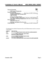
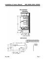
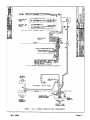
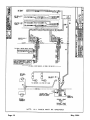
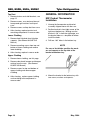
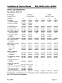
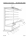
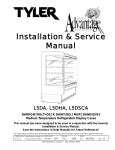
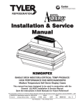
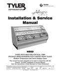
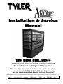
Installation & Service
Manual
N5D, N5DH, N5DL, N5DSC
NARROW MULTI-DECK DAIRY/DELI MERCHANDISERS
Medium Temperature Refrigerated Display Cases
This manual has been designed to be used in conjunction with the
General (UL/NSF) Installation & Service Manual.
Save the Instructions in Both Manuals for Future Reference!!
This merchandiser conforms to the American National Standard Institute & NSF International Health and Sanitation standard ANSI/NSF 7 - 2003.
PRINTED IN Specifications subject to REPLACES
IN U.S.A.
change without notice. EDITION
10/05
ISSUE
DATE
5/06
Tyler Refrigeration * Niles, Michigan 49120
PART
NO.
9037155
REV.
D
N5D, N5DH, N5DL, N5DSC
Tyler Refrigeration
CONTENTS
Page
Specifications
N5D/N5DH/N5DL Specification Sheets . . . . . . . . . . . . . . . . . . . . . . . 4
N5DSC Specification Sheets . . . . . . . . . . . . . . . . . . . . . . . . . . . . . . . 6
Pre-Installation Responsibilities . . . . . (See General-UL/NSF I&S Manual)
Installation Procedures
Carpentry Procedures . . . . . . . . . . . . . . . . . . . . . . . . . . . . . . . . . . . 8
Case Pull-Up Locations . . . . . . . . . . . . . . . . . . . . . . . . . . . . . . . . . . 8
Electrical Procedures . . . . . . . . . . . . . . . . . . . . . . . . . . . . . . . . . . . . 8
Electrical Considerations . . . . . . . . . . . . . . . . . . . . . . . . . . . . . . . . . . 8
Plumbing Procedures . . . . . . . . (See General-UL/NSF I&S Manual)
Refrigeration Procedures . . . . . (See General-UL/NSF I&S Manual)
Defrost Information . . . . . . . . . . . . . . . . . . . . . . . . . . . . . . . . . . . . . 8
Defrost Control Chart . . . . . . . . . . . . . . . . . . . . . . . . . . . . . . . . . . . . 8
Installation Procedure Check Lists (See Gen.-UL/NSF I&S Manual)
Wiring Diagrams . . . . . . . . . . . . . . . . . . . . . . . . . . . . . . . . . . . . . . . . . . . . 8
N5D/N5DH/N5DL Domestic & Export (50Hz) 4’ Case Circuits . . . . . 9
N5D/N5DH/N5DL Domestic & Export (50Hz) 6’ Case Circuits . . . . 10
N5D/N5DH/N5DL Domestic & Export (50Hz) 8’ Case Circuits . . . . 11
N5DSC Domestic & Export (50Hz) 4’ and 6’ Case Circuits . . . . . . 12
Canopy Lighting Circuits . . . . . . . . . . . . . . . . . . . . . . . . . . . . . . . . 13
Optional Shelf Light Circuits . . . . . . . . . . . . . . . . . . . . . . . . . . . . . 14
Cleaning and Sanitation . . . . . . . . . . . . (See General-UL/NSF I&S Manual)
Component Removal and Installation Instructions for Cleaning 15
Mirrors . . . . . . . . . . . . . . . . . . . . . . . . . . . . . . . . . . . . . . . . . . . . . . . 15
Shelves and Shelf Brackets . . . . . . . . . . . . . . . . . . . . . . . . . . . . . . . 15
Bottom Trays . . . . . . . . . . . . . . . . . . . . . . . . . . . . . . . . . . . . . . . . . . 15
Front Air Ducts . . . . . . . . . . . . . . . . . . . . . . . . . . . . . . . . . . . . . . . . 15
Rear Duct Panels . . . . . . . . . . . . . . . . . . . . . . . . . . . . . . . . . . . . . . 15
Discharge Air Honeycomb . . . . . . . . . . . . . . . . . . . . . . . . . . . . . . . . 15
Top Duct . . . . . . . . . . . . . . . . . . . . . . . . . . . . . . . . . . . . . . . . . . . . 16
Lower Cladding . . . . . . . . . . . . . . . . . . . . . . . . . . . . . . . . . . . . . . . . 16
Upper Cladding . . . . . . . . . . . . . . . . . . . . . . . . . . . . . . . . . . . . . . . . 16
Page 2
May, 2004
Installation & Service Manual
N5D, N5DH, N5DL, N5DSC
Page
General Information
NSF Product Thermometer . . . . . . . . . . . . . . . . . . . . . . . . . . . . . . 16
Service Instructions
Preventive Maintenance . . . . . . (See General-UL/NSF I&S Manual)
Troubleshooting Self-Contained Units . . . . . . . . . . . . . . . . . . . . . 17
Light Servicing
Ballast and Lighting Locations . . . . . . . . . . . . . . . . . . . . . . . . . . . . . 18
Fan Blade and Motor Replacement (See Gen.-UL/NSF I&S Manual)
Color Band and Bumper Replacement (See Gen.-UL/NSF I&S Man.)
Parts Information
Operational Parts List . . . . . . . . . . . . . . . . . . . . . . . . . . . . . . . . . . 19
Cladding and Optional Trim Parts List . . . . . . . . . . . . . . . . . . . . . 20
TYLER Warranty . . . . . . . . . . . . . . . . . (See General-UL/NSF I&S Manual)
The following Narrow Medium Temperature Dairy and Deli Merchandiser models are covered
in this manual:
MODELS
DESCRIPTION
N5D
3’, 4’, 6’ & 8’ REMOTE MULTI-DECK DAIRY/DELI MERCHANDISER
N5DH
4’, 6’ & 8’ REMOTE DEEP WELL MULTI-DECK
DAIRY/DELI MERCHANDISER
N5DL
4’, 6’ & 8’ REMOTE LOW FRONT MULTI-DECK
DAIRY/DELI MERCHANDISER
N5DSC
4’ & 6’ SELF-CONTAINED MULTI-DECK DAIRY/DELI MERCHANDISER
November, 2005
Page 3
N5D, N5DH, N5DL, N5DSC
Tyler Refrigeration
SPECIFICATIONS
N5D/N5DH/N5DL Narrow Multi-Deck Dairy/Deli Merchandisers
Page 4
December, 2006
Installation & Service Manual
November, 2005
N5D, N5DH, N5DL, N5DSC
Page 5
N5D, N5DH, N5DL, N5DSC
Tyler Refrigeration
N5DSC Narrow Multi-Deck Dairy/Deli Merchandisers (Self-Contained)
Page 6
December, 2006
Installation & Service Manual
May, 2006
N5D, N5DH, N5DL, N5DSC
Page 7
N5D, N5DH, N5DL, N5DSC
INSTALLATION PROCEDURES
Carpentry Procedures
Case Pull-Up Locations
Tyler Refrigeration
Case Fan Circuit
This circuit is to be supplied by an uninterrupted, protected 120V circuit. The case fan
circuit is not cycled during defrost on any of
these models.
Fluorescent Lamp Circuit
N5D/N5DH/N5DL/N5DSC case lighting is
supplied by 800MA HO horizontal lights. It
is controlled by a light switch in each case.
The standard lighting is 1-row of high output
800MA canopy lights. N5D/N5DH/N5DL/
N5DSC also offers up to 4 rows of T-8 shelf
lights with remote electronic ballasts.
Self-Contained Circuit
N5DSC cases are self-contained units.
Specific information on self-contained units,
not listed on the specifications sheets on
pages 6 and 7, should be obtained directly
from TYLER Refrigeration.
Defrost Information
See “General-UL/NSF I&S Manual” for
operational descriptions for Off Time
defrost control.
Defrost Control Chart
The N5D, N5DH, N5DL and N5DSC models
have four pull-ups at each end of the case.
Pull-ups A, B, C and D are located as shown
and should be install-ed and tightened starting
with A and finishing with D.
See “General-UL/NSF I&S Manual” for lineup assembly instructions.
Electrical Procedures
Electrical Considerations
CAUTION
Make sure all electrical connections at components and terminal blocks are tight.
NOTE
Since the lower front cladding is shipped
loose, the wiring has immediate access.
Page 8
Defrost
Type
N5D(H/L)
Off Time
N5DSC
Off Time
Defrost
Defrosts Duration
Per Day
(Min)
Term.
Temp.
4
24
-----
6
28
-----
WIRING DIAGRAMS
ELECTRICIAN NOTE - OVERCURRENT
PROTECTION
120V circuits should be protected by 15 or 20 Amp
devices per the requirements noted on the cabinet
nameplate or the National Electrical Code, Canadian
Electrical Code - Part 1, Section 28. 208V defrost
circuits employ No. 12 AWG field wire leads for field
connections. On remote cases intended for end to
end line-ups, bonding for ground may rely upon the
pull-up bolts.
The following wiring diagrams on pages 9
thru 14 will cover the N5D, N5DH, N5DL and
N5DSC case circuits and the lighting
circuits.
May, 2004
May, 2004
Page 9
Page 10
May, 2004
May, 2004
Page 11
Page 12
May, 2006
Installation & Service Manual
N5D, N5DH, N5DL, N5DSC
800MA Canopy Lighting Circuit
Optional Canopy Lighting Circuit
May, 2004
Page 13
N5D, N5DH, N5DL, N5DSC
Tyler Refrigeration
Optional Shelf Lighting Circuits 3’ & 4’ Cases
6’ & 8’ Cases
Page 14
November, 2005
Installation & Service Manual
CLEANING AND SANITATION
Component Removal and Installation Instructions for Cleaning
Mirrors
1. Remove mounting screws and end molding of mirror line-up.
2. Carefully grasp and lift mirror section until
bottom edge clears the lower mirror track.
3. Carefully lower mirror out of upper mirror
track and remove from case.
4. After cleaning, replace in reverse order.
Shelves and Shelf Brackets
1. Remove product from shelves.
2. If shelf has a light, unplug the light cord
from the socket in the rear duct panel.
Completely insert socket cover in the light
socket to protect the receptacle.
N5D, N5DH, N5DL, N5DSC
(with Shelf Light Sockets)
1. Remove mirrors, shelves and bottom
trays, see this page.
2. Remove mounting screws from rear duct
panel.
3. Slowly lift out rear duct panel until the
shelf harness connector near the top of
the panel can be accessed.
4. Disconnect shelf harness connector and
complete removing the rear duct panel.
WARNING
Rear duct panels with electrical receptacles can be cleaned without removing the
electrical receptacles. Do not get moisture
on electrical wires when cleaning under
this cover. Moisture on wires could cause
premature product failure and/or personal
injury or death from electrical shock.
3. Push shelves back and then lift up and out
to remove them from the shelf brackets.
5. After cleaning, reconnect the shelf harness connector: install the top socket
assembly: replace and secure rear duct
panels in reverse order.
4. Remove shelf brackets from slots in rear
uprights.
Discharge Air Honeycomb
5. After cleaning, replace in reverse order.
1. Loosen screws securing rear retainer
plate.
Bottom Trays
1. Remove product from bottom of case.
2. Grasp and lift out each of the bottom trays
from the case interior.
3. After cleaning, replace in reverse order.
Front Air Ducts
1. Remove lower trays, see this page.
2. Lift out front air duct sections.
3. After cleaning, replace in reverse order.
Rear Duct Panels
(w/o Shelf Light Sockets)
1. Remove shelves and bottom trays, see
above.
2. Remove mounting screws and rear duct
panels from case.
NOTE
Note position of the honeycomb grid during removal so it can be reinstalled the
same way.
2. Slide rear retainer plate back until the
honeycomb grid sections can be removed
from the top duct.
CAUTION
Improper installation of the honeycomb
grid section could result in improper air
flow and/or poor refrigeration.
3. After cleaning, replace honeycomb grid
sections as they were removed and
secure with the rear retainer plate and
screws.
3. After cleaning, replace and secure rear
duct panels in reverse order.
May, 2004
Page 15
N5D, N5DH, N5DL, N5DSC
Top Duct
1. Remove shelves and shelf brackets, see
page 15.
2. Remove screws, rear retainer plate and
honeycomb grid sections from top of
case.
3. Remove screws and top duct from case.
4. After cleaning, replace top duct and
remaining components in reverse order.
Lower Cladding
1. Remove front kickplate form kickplate
supports. (See General-UL/NSF I&S
Manual.)
2. Remove mounting screws from top and
bottom of lower cladding and remove
lower cladding.
3. After cleaning, replace in reverse order.
Tyler Refrigeration
GENERAL INFORMATION
NSF Product Thermometer
Installation
1. Unwrap the thermometer and bracket
assembly shipped loose with the case.
2. Position bracket in front right corner of the
right-most bottom tray. Making sure the
bracket is 5/8” in from the right edge, use
the bracket holes as a template for where
to drill the holes.
3. Drill two .196” holes in the bottom tray.
NOTE
For ease of installation, position the washers and capnuts on the top side of the
bracket and bottom tray.
Upper Cladding
1. Remove lower cladding, see this page.
2. Remove color band, bumper and bumper
retainer from the case. (See GeneralUL/NSF I&S Manual.)
3. Remove screws for top and bottom of
upper cladding and remove upper
cladding.
4. After cleaning, replace upper cladding
and remaining front components in
reverse order.
Page 16
4. Mount the bracket to the bottom tray with
two screws, washers and capnuts.
May, 2004
Installation & Service Manual
N5D, N5DH, N5DL, N5DSC
SERVICE INSTRUCTIONS
Troubleshooting Self-Contained Units
WARNING
Never work on electrically powered equipment while it is energized! Electrical shock could
cause personal injury and/or death.
TROUBLE
COMMON CAUSE
REMEDY
1. Unit will not run
Blown fuse
Replace fuse.
Low voltage
Check outlet with voltmeter. Voltage
should be 115V or 220V (±10%).
Inoperative motor or
temperature control
Check connections.
Shelves overloaded;
blocked air flow
Make sure items do not block the
air flow.
Thermostat set incorrectly
Check setting.
Pressure control set
incorrectly
Check setting.
Case fans not operating
Check terminal block connections.
Thermostat set incorrectly
Check setting.
Pressure control set
incorrectly
Check setting.
Inadequate air circulation
Relocate cabinet or remove obstruction. Check installation requirements.
Room temperature
too warm
Ventilate room appropriately.
Thermostat set incorrectly
Reset thermostat.
Refrigerant charge low
Have unit serviced by a qualified
service technician.
Loose baffles
Tighten or brace baffles.
Tubing contacting cabinet
or other tubing
Move tubing.
Cabinet not level
Level cabinet.
6. Frost or ice on
evaporator coil
Defrost clock doesn’t work
Check electrical conections. Have
unit serviced by a qualified service
technician.
7. Water dripping from
case drain
Condensate drain clogged
Clear drain.
Dissipator not functioning
Check electrical supply. Check
float assembly.
2. Refrigerated section
is too warm
3. Refrigerated section
too cold
4. Unit runs all the time
5. Noisy operation
May, 2004
Page 17
N5D, N5DH, N5DL, N5DSC
Tyler Refrigeration
Light Servicing
Ballast and Lighting Locations
All light ballasts are located under the canopy
and mounted on the top of the canopy light
channel. This includes remote ballasts for
optional shelf lights. The canopy light(s) are
under the canopy light channel in the top of
the case. The optional shelf lights are mounted in separate light channels under the front
of each shelf section.
NOTE
See “General-UL/NSF I&S Manual” for
800MA and T-8 ballast and lamp, fan blade
& motor and color band & bumper replacement instructions.
Page 18
May, 2004
Installation & Service Manual
N5D, N5DH, N5DL, N5DSC
PARTS INFORMATION
Operational Parts List
Case Usage
Electrical Circuit
Case Size
Domestic
Export
115 Volt 60 Hertz
220 Volt 50 Hertz
4’
6’
8’
4’
6’
8’
Fan Motors
(N5D/N5DH/N5DL)
5125532
5 Watt
5125532
5 Watt
5125532
5 Watt
5126572
5 Watt
5126572
5 Watt
5126572
5 Watt
Fan Motors (N5DSC)
5125532
5 Watt
5125532
5 Watt
----
----
----
----
Fan Motor Brackets
5962269
5962269
5962269
5962269
5962269
5962269
Fan Bracket Plate
9041077
9041077
9041077
9041077
9041077
9041077
Fan Blades (7” 40° 5B)
5221604
5221604
5221604
5221604
5221604
5221604
Opt. ECM Fan Motors
(N5D/N5DH/N5DL)
9025002
8 Watt
9025002
8 Watt
9025002
8 Watt
9025002
8 Watt
9025002
8 Watt
9025002
8 Watt
Opt. ECM Fan Motors
(N5DSC)
9025002
8 Watt
9025002
8 Watt
----
9025002
8 Watt
9025002 ---8 Watt
Opt. ECM Motor Brackets
9025005
9025005
9025005
9025005
9025005
Opt. ECM Fan Blades
(7” 30° 5B)
5223370
5223370
5223370
5223370
5223370 5223370
800MA Ballast (canopy)
5049140
5049140
5049140
5232195
5232195
5232195
Opt. T-8 Ballast
(can. 1-row)
5991029
5991029
5991029
9322286
9322286
9322286
(can. 2-row)
5966635
5966635
5966635
9322286
9322286
9322286
(shelf)
5966635
5966635
5966635
9322288
9322288
9322288
5614628
5614628
5614628
5614628
5614628
5614628
5614629
5614629
5614629
5614629
5614629
5614629
9041897
9041897
9041897
9041897
9041897
9041897
9041897
9041897
9041897
9041897
9041897
9041897
5965977
5965978
----
----
----
----
----
----
----
-------
800MA Lampholder
(telescoping)
(stationary)
T-8 Lampholder (canopy)
(shelf)
Self-Cont. Compressor
(N5DSC)
Compressor Model No.
(N5DSC)
Condensate Pan (N5DSC)
Condensate Pan Heater
(2-8 VAC)(N5DSC)
REK3-0125-PFV REY3-0175-PFV
9601926
5966037
----
----
----
9601906
1500 Watt
9601905
2000 Watt
----
----
----
5967100
5967100
5967100
5967100
NSF Product Thermometer 5967100
9025005
---5967100
For information on operational parts not listed above and for 3’ N5D operational parts, contact
the TYLER Service Parts Department.
May, 2006
Page 19
N5D, N5DH, N5DL, N5DSC
Tyler Refrigeration
Cladding and Optional Trim Parts List
Item Description
N5D/N5DH/N5DL
4’
6’
N5DSC
8’
6’
1
Screw
2
Close-off, Hood
9026366
9026367
9026368
9026366
9026367
3
Can. Hood Joint Trim, Ptd. 9029422
9029422
9029422
9029422
9029422
4
Canopy Hood, Ptd.
9025968
9025969
9025970
9025968
9025969
5
Screw
9025833
9025833
9025833
9025833
9025833
6
Bumper Retainer/Hand Rail
7
Hand Rail Backer, Ptd.
9025316
9025316
9025316
9025316
9025316
8
Color Band, Ptd.
9023791
9023796
9023799
9023791
9023796
9
Color Band Backer, Ptd.
9040223
9040223
9040223
9040223
9040223
10
Bumper
-------------------------
color by order
-------------------------
11
Bumper Backer
-------------------------
color by order
-------------------------
12
Bumper End Trim
-------------------------
color by order
-------------------------
13
Lwr. Frt. Cladding, Ptd.
(N5D / N5DL)
9025459
9025460
9025461
-----
-----
(N5DH)
9026305
9026306
9026307
-----
-----
-----
-----
-----
9603773
9603774
Upr. Frt. Cladding, Ptd.
(N5D / N5DL)
9025462
9025463
9025464
-----
-----
(N5DH)
9026308
9026309
9026310
-----
-----
-----
-----
-----
9025462
9025463
(N5DSC)
14
(N5DSC)
5183536(3) 5183536(4) 5183536(6)
4’
-------------------------
color by order
5183536(10) 5183536(12) 5183536(15)
5183536(3) 5183536(4)
-------------------------
15
Screw
5183536(10) 5183536(12)
16
Kickplate, Ptd.
9039267
9039268
9039269
9039267
9039268
Kickplate Joint Trim, Ptd.
9039020
9039020
9039020
9039020
9039020
Screw
9037551(4) 9037551(5) 9037551(6)
9037551(4) 9037551(5)
17
Screw
9029131(4) 9029131(6) 9029131(8)
9029131(4) 9029131(6)
18
Kickplate Support
9039022(2) 9039022(3) 9039022(4)
9039022(2) 9039022(3)
19
LH End Close-off, Ptd.
9022469
9022469
9022469
9022469
9022469
RH End Close-off, Ptd.
9022471
9022471
9022471
9022471
9022471
20
Screw
5048626(2) 5048626(2) 5048626(2)
5048626(2) 5048626(2)
For information on 3’ N5D cladding and optional trim parts, contact the TYLER Service Parts
Department.
Page 20
November, 2005
Installation & Service Manual
May, 2004
N5D, N5DH, N5DL, N5DSC
Page 21