1
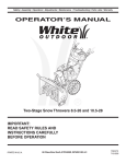
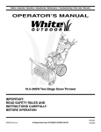
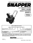
Safety • Set-Up • Operation • Adjustments • Maintenance • Troubleshooting • Parts Lists • Warranty
OPERATOR’S MANUAL
www.troybilt.ca
Two-Stage Snow Thrower
IMPORTANT:
READ SAFETY RULES AND
INSTRUCTIONS CAREFULLY
BEFORE OPERATING EQUIPMENT.
PRINTED IN U.S.A.
P. O. Box 1386, KITCHENER, ONTARIO N2G 4J1
769-04090
06/10/08
This Operator’s Manual is an important part of your new snow thrower. It will help you assemble,
prepare and maintain the unit for best performance. Please read and understand what it says.
Table of Contents
Safety Symbols.................................................... 3
Safe Operation Practices.................................... 4
Setting Up Your Snow Thrower........................... 6
Operating Your Snow Thrower.......................... 10
MakingAdjustments.......................................... 14
Maintaining Your Snow Thrower....................... 16
Off-Season Storage........................................... 20
Trouble Shooting............................................... 21
Warranty............................................................. 22
Illustrated Parts Lists........................................ 24
Finding and Recording Model Number
BEFORE YOU START ASSEMBLING
YOUR NEW EQUIPMENT,
please locate the model plate on the equipment and copy the
model number and the serial number to the sample model
plate provided to the right. You can locate the model plate by
standing at the operating position and looking down at the
frame.
-ODEL.UMBER
.UM£RODEMODÞLE
888888888
3ERIAL.UMBER
.UM£RODES£RIE
88888888888
42/9"),4#!.!$!
+)4#(%.%2/..'*
Customer Support
Please do NOT return the unit to the retailer from which it was purchased,
without first contacting Customer Support.
If you have difficulty assembling this product or have any questions regarding the controls, operation or maintenance of this unit,
you can seek help from the experts. Choose from the options below:
1. Visit www.troybilt.ca/troybilt for many useful suggestions.
2. Call an authorized dealer or Customer Support Representative at 1-800-668-1238.
3. The engine manufacturer is responsible for all engine-related issues in terms of performance, power-rating, specifications,
warranty, and service. Depending on the engine manufacturer, more information is included in this publication or packed
separately with this product.
Please have your unit’s model number and serial number ready when you call. See previous section to locate this information.
You will be asked to enter the serial number in order to process your call.
2
This page depicts and describes safety symbols that may appear on this product. Read, understand, and follow all
instructions on the machine before attempting to assemble and operate.
Symbol
Description
READ THE OPERATOR’S MANUAL(S)
Read, understand, and follow all instructions in the manual(s) before
attempting to assemble and operate.
1
Safety
Symbols
WARNING— ROTATING BLADES
Keep hands out of inlet and discharge openings while machine is running.
There are rotating blades inside.
WARNING— ROTATING BLADES
Keep hands out of inlet and discharge openings while machine is running.
There are rotating blades inside.
WARNING— ROTATING AUGER
Do not put hands or feet near rotating parts, in the auger/impeller housing
or chute assembly. Contact with the rotating parts can amputate hands and
feet.
WARNING—THROWN OBJECTS
This machine may pick up and throw and objects which can cause serious
personal injury.
WARNING—GASOLINE IS FLAMMABLE
Allow the engine to cool at least two minutes before refueling.
WARNING— CARBON MONOXIDE
Never run an engine indoors or in a poorly ventilated area. Engine exhaust
contains carbon monoxide, an odorless and deadly gas.
WARNING— ELECTRICAL SHOCK
Do not use the engine’s electric starter in the rain.
WARNING
This symbol points
out important safety
instructions which,
if not followed, could
endanger the personal safety and/or
property of yourself
and others. Read and
follow all instructions
in this manual before
attempting to operate
this machine. Failure
to comply with these
instructions may
result in personal
injury. When you see
this symbol, HEED
ITS WARNING!
Your Responsibility
Restrict the use
of this power machine
to persons who read,
understand
and follow the warnings
and instructions
in this manual
and on the machine.
3
2
Safe
Operation
Practices
WARNING
This symbol points
out important safety
instructions which,
if not followed, could
endanger the personal safety and/or
property of yourself
and others. Read and
follow all instructions
in this manual before
attempting to operate
this machine. Failure
to comply with these
instructions may
result in personal
injury. When you see
this symbol, HEED
ITS WARNING!
Your Responsibility
Restrict the use
of this power machine
to persons who read,
understand
and follow the warnings
and instructions
in this manual
and on the machine.
WARNING: Engine Exhaust, some of its constituents, and certain vehicle components contain or emit chemicals known to State of California to cause cancer and
birth defects or other reproductive harm.
DANGER: This machine was built to be operated according to the safe operation practices in this
manual. As with any type of power equipment, carelessness or error on the part of the operator can
result in serious injury. This machine is capable of amputating hands and feet and throwing objects.
Failure to observe the following safety instructions could result in serious injury or death.
Training
Safe Handling of Gasoline
1. Read, understand, and follow all instructions on the
machine and in the manual(s) before attempting to
assemble and operate. Keep this manual in a safe place for
future and regular reference and for ordering replacement
parts.
2. Be familiar with all controls and their proper operation.
Know how to stop the machine and disengage them quickly.
3. Never allow children under 14 years old to operate this
machine. Children 14 years old and over should read and
understand the instructions and safe operation practices
in this manual and on the machine and be trained and
supervised by an adult.
4. Never allow adults to operate this machine without proper
instruction.
5. Thrown objects can cause serious personal injury. Plan
your snow-throwing pattern to avoid discharge of material
toward roads, bystanders and the like.
6. Keep bystanders, helpers, pets and children at least 75 feet
from the machine while it is in operation. Stop machine if
anyone enters the area.
7. Exercise caution to avoid slipping or falling, especially
when operating in reverse.
To avoid personal injury or property damage use extreme care
in handling gasoline. Gasoline is extremely flammable and the
vapors are explosive. Serious personal injury can occur when
gasoline is spilled on yourself or your clothes, which can ignite.
Wash your skin and change clothes immediately.
Preparation
Thoroughly inspect the area where the equipment is to be
used. Remove all doormats, newspapers, sleds, boards, wires
and other foreign objects, which could be tripped over or
thrown by the auger/impeller.
1. Always wear safety glasses or eye shields during
operation and while performing an adjustment or repair
to protect your eyes. Thrown objects which ricochet can
cause serious injury to the eyes.
2. Do not operate without wearing adequate winter outer garments. Do not wear jewelry, long scarves or other loose
clothing, which could become entangled in moving parts.
Wear footwear which will improve footing on slippery
surfaces.
3. Use a grounded three-wire extension cord and receptacle
for all units with electric start engines.
4. Adjust collector housing height to clear gravel or crushed
rock surfaces.
5. Disengage all control levers before starting the engine.
6. Never attempt to make any adjustments while engine is
running, except where specifically recommended in the
operator’s manual.
7. Let engine and machine adjust to outdoor temperature
before starting to clear snow.
4
a. Use only an approved gasoline container.
b. Extinguish all cigarettes, cigars, pipes and other sources
of ignition.
c. Never fuel machine indoors.
d. Never remove gas cap or add fuel while the engine is hot
or running.
e. Allow engine to cool at least two minutes before refueling.
f. Never over fill fuel tank. Fill tank to no more than ½ inch
below bottom of filler neck to provide space for fuel
expansion.
g. Replace gasoline cap and tighten securely.
h. If gasoline is spilled, wipe it off the engine and equipment. Move machine to another area. Wait 5 minutes
before starting the engine.
i. Never store the machine or fuel container inside where
there is an open flame, spark or pilot light (e.g. furnace,
water heater, space heater, clothes dryer etc.).
j. Allow machine to cool at least 5 minutes before storing
k. Never fill containers inside a vehicle or on a truck or
trailer bed with a plastic liner. Always place containers on
the ground away from your vehicle before filling.
l. If possible, remove gas-powered equipment from the
truck or trailer and refuel it on the ground. If this is not
possible, then refuel such equipment on a trailer with a
portable container, rather than from a gasoline dispenser
nozzle.
m.Keep the nozzle in contact with the rim of the fuel tank or
container opening at all times until fueling is complete.
Do not use a nozzle lock-open device.
Operation
Maintenance & Storage
1. Do not put hands or feet near rotating parts, in the auger/
impeller housing or chute assembly. Contact with the
rotating parts can amputate hands and feet.
2. The auger/impeller control lever is a safety device. Never
bypass its operation. Doing so makes the machine unsafe
and may cause personal injury.
3. The control levers must operate easily in both directions
and automatically return to the disengaged position when
released.
4. Never operate with a missing or damaged chute assembly.
Keep all safety devices in place and working.
5. Never run an engine indoors or in a poorly ventilated area.
Engine exhaust contains carbon monoxide, an odorless and
deadly gas.
6. Do not operate machine while under the influence of alcohol
or drugs.
7. Muffler and engine become hot and can cause a burn. Do
not touch.
8. Exercise extreme caution when operating on or crossing
gravel surfaces. Stay alert for hidden hazards or traffic.
9. Exercise caution when changing direction and while operating on slopes.
10.Plan your snow-throwing pattern to avoid discharge towards
windows, walls, cars etc. Thus, avoiding possible property
damage or personal injury caused by a ricochet.
11.Never direct discharge at children, bystanders and pets or
allow anyone in front of the machine.
12.Do not overload machine capacity by attempting to clear
snow at too fast of a rate.
13.Never operate this machine without good visibility or light.
Always be sure of your footing and keep a firm hold on the
handles. Walk, never run.
14.Disengage power to the auger/impeller when transporting or
not in use.
15.Never operate machine at high transport speeds on slippery
surfaces. Look down and behind and use care when
backing up.
16.If the machine should start to vibrate abnormally, stop the
engine, disconnect the spark plug wire and ground it against
the engine. Inspect thoroughly for damage. Repair any
damage before starting and operating.
17.Disengage all control levers and stop engine before you
leave the operating position (behind the handles). Wait
until the auger/impeller comes to a complete stop before
unclogging the chute assembly, making any adjustments, or
inspections.
18.Never put your hand in the discharge or collector openings.
Always use the clean-out tool provided to unclog the discharge opening. Do not unclog chute assembly while engine
is running. Shut off engine and remain behind handles until
all moving parts have stopped before unclogging.
19.Use only attachments and accessories approved by the
manufacturer (e.g. wheel weights, tire chains, cabs etc.).
20.When starting engine, pull cord slowly until resistance is felt,
then pull rapidly. Rapid retraction of starter cord (kickback)
will pull hand and arm toward engine faster than you can let
go. Broken bones, fractures, bruises or sprains could result.
21.If situations occur which are not covered in this manual, use
care and good judgment. Call customer assistance for the
name of your nearest servicing dealer.
1. Never tamper with safety devices. Check their proper
operation regularly. Refer to the maintenance and adjustment sections of this manual.
2. Before cleaning, repairing, or inspecting machine disengage
all control levers and stop the engine. Wait until the auger/
impeller come to a complete stop. Disconnect the spark plug
wire and ground against the engine to prevent unintended
starting.
3. Check bolts and screws for proper tightness at frequent
intervals to keep the machine in safe working condition.
Also, visually inspect machine for any damage.
4. Do not change the engine governor setting or over-speed
the engine. The governor controls the maximum safe
operating speed of the engine.
5. Snow thrower shave plates and skid shoes are subject to
wear and damage. For your safety protection, frequently
check all components and replace with original equipment
manufacturer’s (OEM) parts only. “Use of parts which do
not meet the original equipment specifications may lead to
improper performance and compromise safety!”
6. Check controls periodically to verify they engage and
disengage properly and adjust, if necessary. Refer to the
adjustment section in this operator’s manual for instructions.
7. Maintain or replace safety and instruction labels, as necessary.
8. Observe proper disposal laws and regulations for gas, oil,
etc. to protect the environment.
9. Prior to storing, run machine a few minutes to clear snow
from machine and prevent freeze up of auger/impeller.
10.Never store the machine or fuel container inside where
there is an open flame, spark or pilot light such as a water
heater, furnace, clothes dryer etc.
11.Always refer to the operator’s manual for proper instructions
on off-season storage.
12.Check fuel line, tank, cap, and fittings frequently for cracks
or leaks. Replace if necessary.
13.Do not crank engine with spark plug removed.
Do not modify engine
To avoid serious injury or death, do not modify engine in any
way. Tampering with the governor setting can lead to a runaway
engine and cause it to operate at unsafe speeds. Never tamper
with factory setting of engine governor.
Notice regarding Emissions
Engines which are certified to comply with California and federal
EPA emission regulations for SORE (Small Off Road Equipment)
are certified to operate on regular unleaded gasoline, and may
include the following emission control systems: Engine Modification (EM) Oxidizing Catalyst (OC), Secondary Air Injection (SAI)
and Three Way Catalyst (TWC) if so equipped.
Average Useful Life
According to the Consumer Products Safety Commission
(CPSC) and the U.S. Environmental Protection Agency (EPA),
this product has an Average Useful Life of seven (7) years, or
60 hours of operation. At the end of the Average Useful Life,
have the machine inspected annually by an authorized service
dealer to ensure that all mechanical and safety systems are
working properly and not worn excessively. Failure to do so can
result in accidents, injuries or death.
05.08.08
5
2
Safe
Operation
Practices
WARNING
This symbol points
out important safety
instructions, which
if not followed, could
endanger the personal safety and/or
property of yourself
and others. Read and
follow all instructions
in this manual before
attempting to operate
this machine. Failure
to comply with these
instructions may
result in personal
injury. When you see
this symbol, HEED
IT’S WARNING!
Your Responsibility
Restrict the use
of this power machine
to persons who read,
understand
and follow the warnings
and instructions
in this manual
and on the machine.
3
IMPORTANT: The snow thrower is shipped with oil and
WITHOUT GASOLINE. After assembly, refer to separate
engine manual for proper fuel and engine oil recommendations.
Loose Parts
Setting Up
Your Snow
Thrower
• The augers are secured to the auger shaft with shear
pins and bow tie cotter pins. If you hit a foreign object
or ice jam, the snow thrower is designed so that the
pins may shear. Replacement shear pins and cotter
pins are provided for your convenience. Store these
safely until needed.
Items Required For Assembly
Pair of pliers Fresh gasoline
7/16” Wrenches or adjustables
Figure 3-1
NOTE: This Operator’s
Manual covers several
models. Snowthrower
featrues vary by model.
Not all features referenced in this manual
are applicable to all
snowthrower models.
NOTE: References to
right or left side of the
snow thrower are determined from behind the
unit in the operating
position.
Assembling Handle
• Look at the lower rear of the snow thrower frame to
be sure the spring (found at the end of each cable) is
attached to its actuator bracket.
• Remove the lower handle knobs, washers and
carriage bolts from each side of the upper handle.
See Figure 3-2.
• Raise the upper handle assembly until it locks over
the lower handle. See Figure 3-1.
• Secure the upper handle and lower handle with the
handle knobs and carriage bolts previously removed.
• Tighten the handle knobs already in place on the
upper holes and secure the handles firmly.
Figure 3-2
NOTE: Replacement
auger shear pins and
cotter pins are provided
for your convenience.
Store these safely until
needed.
Attaching Chute Crank
• Remove the hairpin clip from the upper chute crank
and slide the upper chute crank into the lower chute
crank. A pair of pliers may help in this job. See Figure
3-3.
a. Align the two holes on both chute cranks. See
Figure 3-3.
a
b. Secure with the hairpin clip removed earlier.
b
Figure 3-3
6
3
Setting Up
Your Snow
Thrower
Figure 3-4
Figure 3-5
Attaching the Chute Assembly
• Remove locknuts and screws securing one of the
flange keepers to the chute assembly. See Figure 3-4.
WARNING
• Loosen but do not remove the locknuts and screws on
the other two flange keepers.
Prior to operating
your snow thrower,
refer to Auger Control
on page 9. Read and
follow all instructions
carefully and perform
all adjustments to
verify your unit is
operating safely and
properly.
• Slide chute assembly over chute opening, making
sure the flange keepers are beneath lip of chute
adapter. The notches should engage with the spiral
end of the chute crank. See Figure 3-5.
• Secure flange keeper, locknuts and screws previously
removed. Tighten all flange keepers and hardware
with two 7/16” wrenches. Do not over tighten.
NOTE: If necessary the chute crank support bracket can
be adjusted so the spiral on the chute crank fully engages
the teeth on the chute assembly. Refer to the Adjustment
Section.
Attaching the Shift Rod
• Align the upper and lower shift rods, then slide the
shift rod connector down over the end of the lower
shift rod. Tap the connector until the lower rod is
completely through the connector. See Figure 3-6.
Figure 3-6
NOTE: If the connector is not properly assembled, the
shift rod will pivot and you will not be able to change
speeds or direction.
NOTE: If the full range of speeds (forward and reverse)
cannot be achieved, refer to the Adjustment Section.
• Normally the cable ties holding the steering cables
against the handle are loosely installed on each side
of the lower handle at the factory. Pull the cable ties
tight to secure. Cut the excess from the ends of cable
ties.
• If not already attached, slip the cables that run from
the handle panel to the discharge chute into the cable
guide. See Figure 3-7.
Figure 3-7
7
3
Lamp Wiring
Drift Cutters (If Equipped)
• Wrap the wire from the head lamp down the right
handle until the wire can be plugged into the alternator lead wire under the fuel tank. See Figure 3-8.
Drift cutters should be used when operating the snow
thrower in heavy drift conditions.
Setting Up
Your Snow
Thrower
• On models so equipped, drift cutters and hardware
are assembled to the auger housing inverted.
• Remove the carriage bolts and wingnuts securing the
drift cutters to the housing.
Alternator Lead
• Reposition drift cutters so they face forward as
shown in Figure 3-9. Secure with hardware previously
removed, wingnuts should be fastened on the outside
of the housing as shown.
Alternator
Lead
If your unit is not equipped with drift cutters, you may
contact Customer Support as instructed on page 2 for
information regarding price and availability.
Lamp Wire
NOTE: Wheels are omitted from illustration for clarity.
Figure 3-8
Snowthrower Model
Drift Cutter Kit:
All models
OEM-390-679
Clean-Out Tool
WARNING
The clean-out tool is mounted to the rear of the auger
housing and is designed to clear a clogged chute. See
Figure 3-10. Refer to the Operation section for more
detailed information regarding the chute clean-out tool.
Never use your hands
to clean snow and
ice from the chute
assembly or auger
housing.
NOTE: This item is fastened with a cable tie to the rear of
the auger housing at the factory. Cut the cable tie before
operating the snow thrower.
WARNING: Never use your hands to
clean snow and ice from the chute
assembly or auger housing.
Final Adjustments
IMPORTANT
Under any circumstance do not exceed
manufacturer’s recommended psi. Equal tire
pressure should be
maintained at all times.
Excessive pressure
when seating beads
may cause tire/rim
assembly to burst
with force sufficient to
cause serious injury.
Refer to sidewall of
tire for recommended
pressure.
Make these final adjustments before operating your snow
thrower for the first time. Failure to follow these instructions may cause damage to the snow thrower.
Figure 3-9
Wheel Drive Control & Shift Lever
Perform the following test to determine need for adjustment:
• Move the shift lever into sixth (6) position. See Figure
3-14.
Clean-Out
Tool
• With the drive control released (see Figure 3-11A),
push the snow thrower forward, then pull it back. The
machine should move freely.
• Engage the drive control and attempt to move the
machine both forward and back, resistance should be
felt.
• Move the shift lever into the fast reverse (R2) position
and repeat the previous two steps.
If you experienced resistance rolling the unit, either
when repositioning the shift lever from 6 to R2 or when
attempting to move the machine with the drive control
released, adjust the drive control immediately. To adjust,
proceed as follows:
Figure 3-10
8
3
B
A
A
Auger
Drive
Setting Up
Your Snow
Thrower
Figure 3-11
• Loosen the Nylock nut on the drive control cable and
unthread the cable one full turn. See Figure 3-13.
B
• Recheck adjustment.
A - For models with steel panels.
B - For models with plastic panels.
• Retighten the Nylock nut to secure the cable when
correct adjustment is reached.
Figure 3-12
NOTE: For more details, refer to Drive Control Adjustment in the Adjustment Section of this manual.
WARNING
Auger Control
Check the adjustment of the auger control as follows:
Never use your hands
to clean snow and
ice from the chute
assembly or auger
housing.
• When the auger control is released and in the
disengaged “up” position (see Figure 3-11B), the cable
should have very little slack, but should NOT be tight.
See Figure 3-12.
WARNING:Do not over-tighten the
cable. Over-tightening may prevent the
auger from disengaging and compromise the safety of the snow thrower.
• In a well-ventilated area, start the snow thrower engine
as instructed on page 12.
• While standing in the operator’s position (behind the
snow thrower) engage the auger.
• Allow the auger to remain engaged for approximately
ten seconds before releasing the auger control.
Repeat this several times.
• With the auger control lever in the disengaged “up”
position, walk to the front of the machine.
• Confirm that the auger has completely stopped
rotating and shows no signs of motion.
IMPORTANT: If the auger shows any signs of rotating,
immediately return to the operator’s position and shut
off the engine. Wait for all moving parts to stop before
readjusting the auger control cable.
Figure 3-13
• Repeat auger control test to verify for proper
adjustment. Repeat previous steps to adjust more, if
necessary.
Skid Shoes
Position the skid shoes based on surface conditions.
Adjust upward for hard-packed snow. Adjust downward
when operating on gravel or crushed rock surfaces. See
“Making Adjustment” Section.
Tire Pressure (Pneumatic Tires)
The tires are over-inflated for shipping purposes.
Check the tire pressure before operating the snow
thrower. Refer to the tire side wall for tire manufacturer’s
• To readjust the control cable, unhook the spring (found recommended psi and deflate (or inflate) the tires as
on the end of the auger cable) from the auger actuator necessary.
bracket. See Figure 3-12.
• Push the cable coupler through the end of the spring
to expose the lock nut. See Figure 3-13.
• Thread the Nylock nut outward (down the coupler)
three full turns to provide more slack in the cable and
reattach the spring to the bracket.
9
IMPORTANT
If the tire pressure is not
equal in both tires, the unit
may not travel in a straight
path and the shave plate
may wear unevenly.
4
Know Your Snow Thrower
Shift Lever
Drive Control
Operating
Your Snow
Thrower
Two-Way Chute Control™
Headlight
Auger Control
Wheel Steering Control
Chute Assembly
Chute Direction Control
Clean-Out Tool
Choke
Control
Engine Controls
Gas Cap
Primer
Oil Fill
Electric Start
Button
(optional)
WARNING
Read, understand,
and follow all instructions and warnings
on the machine and
in this manual before
operating.
Use extreme care
when handling
gasoline. Gasoline is
extremely flammable
and the vapors are
explosive. Never fuel
the machine indoors
or while the engine
is hot or running.
Extinguish cigarettes,
cigars, pipes and
other sources of
ignition.
Safety
Key
Augers
Skid Shoe
Recoil Starter
Handle
Rocker
Switch
Electric Starter
Outlet
(optional)
Figure 4-1
Now that you have set up your snow thrower for operation, get acquainted with its controls and features. These
are described below and illustrated on this page. This
knowledge will allow you to use your new equipment to
its fullest potential.
NOTE: For detailed starting instructions and more
information on all engine controls, refer to the separate
engine manual packed with your unit.
Choke Control
The choke control is found on top of the
engine and is activated by rotating the knob
counter clockwise. Activating the choke
control closes the choke plate on the carburetor and aids in starting the engine.
Primer
Depressing the primer forces fuel directly into the engine’s
carburetor to aid in cold-weather starting.
Shift Lever
The shift lever is located in the center of
the handle panel and is used to determine
ground speed and direction of travel. It can
be moved into any of eight positions.
6
IMPORTANT: Always release drive control
before changing speeds.
2
1
Forward: The snow thrower has six
forward (F) speeds. Position one (1) is the
slowest and position six (6) is the fastest.
Reverse: The snow thrower has two
reverse (R) speeds—R1 is the slower of
the two.
Oil Fill
Engine oil level can be checked and oil added through the
oil fill.
5
4
Safety Key
The safety key must be pushed in place in order for the
engine to start. Pull the safety key out to prevent unauthorized use of equipment.
3
F
Rocker Switch
The rocker switch is used to stop the engine. The switch
must be in the “ON” position in order to start the engine.
R R1
R2
10
Auger Control
The auger control is located on the left handle. Squeeze
the auger control to engage the augers. Release to stop
the snow throwing action. The drive control must also be
released in order to stop auger.
Two-Way Chute Control™)
This two-way control lever is meant to
control the distance of snow discharge from
the chute. Tilt the lever forward or rearward
to adjust the distance snow will be thrown.
!5'%2
#/.42/,
Chute Directional Control
The chute directional control is
located on left side of the snow
thrower.
To change the direction in which
snow is thrown, turn chute directional
control as follows:
• Crank clockwise to discharge to
the left.
'/
CLOCKWISE TO
DISCHARGE LEFT
COUNTER CLOCKWISE
TO DISCHARGE RIGHT
4
Operating
Your Snow
Thrower
• Crank counterclockwise to discharge to the right.
Drive Control / Auger Control Lock
The drive control is located on the right handle. Squeeze
the drive control to engage the wheel drive. Release to
stop.
This same lever also locks the auger control so you
can operate the chute crank without interrupting the
snow throwing process. If the auger control is engaged
simultaneously with the drive control, the operator can
release the auger control (on the left handle) and the
augers will remain engaged. Release the drive control to
stop the augers and wheel drive (the auger control must
also be released).
Wheel Steering Controls
The left and right wheel steering
controls are located on the underside
of the handles. Squeeze the right
control to turn right; squeeze the left
control to turn left.
NOTE: Operate the snow thrower in open areas until you
are familiar with these controls.
IMPORTANT: NEVER reposition the shift lever (change
speeds or direction of travel) without first releasing the
drive control and bringing the snow thrower to a complete
stop. Doing so will result in premature wear to the snow
thrower’s drive system.
$2)6%
#/.42/,
Chute Clean-Out Tool
WARNING: Never use your hands to
clear a clogged chute assembly. Shut
off engine and remain behind handles
until all moving parts have stopped
before unclogging.
The clean-out tool is conveniently fastened to the rear of
the auger housing with a mounting clip.
1. Release both the auger control and the drive/auger
control lock.
2. Stop the engine by pushing the rocker switch to the
“OFF” position, pull out the safety key.
3. Remove the clean-out tool from the mounting clip.
4. Use the shovel-shaped end of the clean-out tool to
remove any snow and ice in the chute assembly.
'/
5. Re-fasten the clean-out tool to the mounting clip on
the rear of the auger housing and restart engine.
6. While standing in the operator’s position (behind the
snow thrower), engage the auger control for a few
seconds to clear any remaining snow or ice from the
chute assembly before continuing to clear snow.
Skid Shoes
Position the skid shoes based on surface conditions.
Adjust upward for hard-packed snow. Adjust downward
when operating on gravel or crushed rock surfaces. See
“Making Adjustment” Section.
Headlight
The headlight is on whenever the engine is running.
11
WARNING
The operation of
any snow thrower
can result in foreign
objects being thrown
into the eyes, which
can damage your
eyes severely. Always
wear safety glasses
while operating the
snow thrower, or while
performing any adjustments or repairs on it.
Be sure no one other
than the operator is
standing near the snow
thrower while starting
engine or operating
snow thrower. Never
run engine indoors or
in enclosed, poorly
ventilated areas. Engine exhaust contains
carbon monoxide, an
odorless and deadly
gas. Keep hands, feet,
hair and loose clothing
away from any moving
parts on engine and
snow thrower.
4
Operating
Your Snow
Thrower
Gas & Oil Fill-Up
Service the engine with gasoline and oil as instructed in
the separate engine manual packed with your unit. Read
instructions carefully.
Starting The Engine
1. Make certain both the auger control and drive control
are in the disengaged (released) position.
2. Open fuel shut-off valve (If equipped) and make sure
the Rocker switch is in the On position (if equipped).
3. Push in the safety key.
4. Rotate choke control to FULL choke position
(for a cold engine start).
WARNING
Read, understand,
and follow all instructions and warnings
on the machine and
in this manual before
operating.
Use extreme care
when handling
gasoline. Gasoline is
extremely flammable
and the vapors are
explosive. Never fuel
the machine indoors
or while the engine
is hot or running.
Extinguish cigarettes,
cigars, pipes and
other sources of
ignition.
NOTE: If the engine is already warm, place choke
co