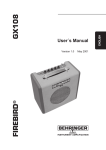
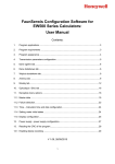
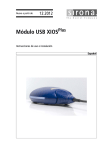
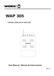
1
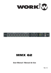
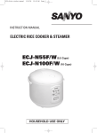
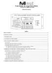
MAX SERIES
MAX 4.2, 6.2, 8.2
User Manual / Instrucciones de Usuario
Rev. 12.10.01
MAX SERIES
MAX 4.2, 6.2, 8.2
4, 6, 8 INPUT CHANNELS
MIXING SERIES
SERIE DE MEZCLADORES
DE 4, 6 y 8 ENTRADAS
ENGLISH
ESPAÑOL
Page 1
Página 7
This symbol on the product or on its packaging indicates that this product
shall not be trated as household waste. Instead it shall be handed over to
the applicable collection point for the recycling of electrical an electronic
equipment. By ensuring this product is disposed of correctly, you will help
prevent potential negative consequences for the environment and human
health, which could otherwise be caused by inappropriate waste handling
of this product. The recycling of amterials will help to conserve natural
resources. For more detailed information sabout recycling of this product,
please contact your local city office, your household waste disposal service
or the shop where you purchased the product.
Este símbolo en su equipo o embalaje, indica que el presente producto
no puede ser tratado como residuos domésticos normales, sino que deben
entregarse en el correspondiente punto de recogida de equipos electrónicos
y eléctricos. Asegurándose de que este producto es desechado
correctamente, Ud. está ayudando a prevenir las consecuencias negativas
para el medio ambiente y la salud humana que podrían derivarse de la
incorrecta manipulación de este producto. EL reciclaje de materiales
ayuda a conservar las reservas naturales. Para recibir más información,
sobre el reciclaje de este producto, contacte con su ayuntamiento, su
punto de recogida más cercano o el distribuidor donde adquirió el producto.
EN
SAFETY INSTRUCTIONS
CAUTION:
WARNING:
To reduce the risk of electrical shock, do not remove
the cover (or back). No user serviceable parts inside;
refer servicing to qualified personnel.
CAUTION
RISH OF ELECTRIC SHOCK
DO NOT OPEN
To reduce the risk of fire or electrical shock, do not
expose this appliance to rain or moisture.
This symbol, wherever it appears, alerts
you to the presence of uninsulated
dangerous voltage inside the enclosure
- voltage that may be sufficient to
constitute a risk of shock.
This symbol, wherever it appears, alerts
you to the important operating and
maintenance instructions in the
accompanying literature. Read the
manual.
DETAILED SAFETYINSTRUCTIONS:
All the safety and operation instructions should be read before the appliance is operated.
Retain Instructions:
The safety and operating instructions should be retained for future reference.
Heed Warnings:
All warnings on the appliance and in the operating instructions should be adhered to.
Follow instructions:
All operation and user instructions should be followed.
Water and Moisture:
The appliance should not be used near water (e.g. near a bathtub, washbowl, kitchen sink, laundry tub, in a wet
basement, or near a swimming pool etc.).
Ventilation:
The appliance should be situated so that its location or position does not interfere with its proper ventilaton. For
example, the appliance should not be situated on a bed, sofa rug, or similar surface that may block the
ventilation openings:or placed in a built-in installation, such as a bookcase or cabinet that may impede the
flow of air through the ventilation openings.
Heat:
The appliance should be situated away from heat sources such as radiators, heat registers, stoves or other
appliances (including amplifiers) that produce heat.
Power Source:
The appliance should be connected to a power supply only of the type described in the operating instructions
or as marked on the appliance.
Grounding or Polarization:
Precautions should be taken so that the grounding or polarization means of an appliance is not defeated.
Power-Cord Protection:
Power supply cords should be routed so that they are not likely to be walded on or pinched by items placed
upon or against them, paying particular attention to cords and plugs, convenience receptacles and the point
where they exit from the appliance.
Cleaning:
The appliance should be cleaned only as recommended by the manufacturer.
Non-use Periods:
The power cord of the appliance should be unplugged from the outlet when left unused for a long period of time.
Object and Liquid Entry:
Care should be taken so that objects do not fall and liquids are not spilled into the enclosure through openings.
Damage Requiring Sercice:
The appliance should be serviced by qualified service personnel when:
-the power supply cord or the plug has been damaged;or
-objects have fallen, or liquid has been spilled into the appliance or
-the appliance has been exposed to rain; or
-the appliance does not appear to operate normally or exhibits a marked change in performance;or
-the appliance has been dropped, or the enclosure damaged.
Servicing:
The user should not attempt to service the appliance beyond that which is described in the Operating Instructions.
All other servicing should be referred to qualified service personnel.
MAX 4.2, 6.2, 8.2
User Manual/Manual de uso
Pag. 1
EN
PROFESSIONAL 4,6, 8-channel mixing console and Aux paths plus effects processor
4, 6, 8-channel mixing console with two stereo channels and a separate stereo tape
channel
Separate input JACK controls for mix and line inputs noall mono channels
XLR mic connectors on all mono channels
Low-noise, discrete mic preamplifiers on all microphone inputs
Dedicated inserts on all mono channels
Balanced 1/4 " stereo jacks and balance controls on all stereo channels
Separate stereo tape channel with 1/4 " and RCA jacks
Stereo output for recording applications
Active 3-babd EQ on all channels
AUX and effects paths as well as separate gain controls on all channels
High-grade-sealed faders and potentiometers
Insert option for extemal effects devices
AUX Send and EFF Send controls in the main section for optimal level adjustment
Headphones output with dedicated volime control
Built-in +48V phantom power for condenser mics
Extremely rugged construction ensures long life even under the most demanding conditions
1. INTRODUCTION
Congratulations!
Our prime goal when develping the machine was to design a console that can be used for a
great variety of applications. And to give you maximum flexibility.
In combination with its comprehensive range of featrues and pro-level connections, the machine will by your
perfect tool for any kind of application: broadcasting, video dubbing or giving the sound of your band its finishing
touch.
1.1 Before you begin
Your machine was carefully packed in the factory and the packaging is designed to protect the
unit from rough handling. Nevertheless, we recommend that you carefully examine the packaging and its
contents for any signs of physical damage, which may have occurred during transit.
If the unit is damaged, please do not return it to our company, but notify your dealer and
the shipping company immediately, otherwise claims for damage or replacement may not
be granted.
Be sure that there is enough space around the unit for cooling and please do not place the machine
on high-temperature devices such as radiators, etc to avoid overheating.
1.2
Control elements
1.2.1 Interface panel
1
Use this balanced XLR jack to connect a microphone to the machine (applies to mono channels)
The phantom power required for condenser mies can be activated with switch
17
.
2
The INSERT jack allows you to insert, for example, a compressor or equalizer in the mono channels.
3
Mono channels feature an addditional
4
These are the two balanced LINE inputs on 1/4 jacks for the left and right sides of the stereo channels,
5
The TAPE IN jacks (on stereo RCA) allow for the connection of play-back devices such as CD players, etc.
LINE input on a balanced 1/4 " jack.
which can be used in parallel to the microphone inputs.
MAX 4.2, 6.2, 8.2
User Manual/Manual de uso
Pag. 2
EN
6
Use the TAPE OUT jacks to connect, for example, a tape deck for recording applications.
7
Use the PHONES jack to connect a commercially available pair of headphones.
8
These are the balanced 1/4
' jack MAIN OUTPUTS of your machine that can be used to drice, e.g.a
power amplifier.
9
10
Connect the EFF SEND connector to the input of an external effects device.
The AUX SEND connector provides the monitor signal of your machine, for example, to control a
monitor amplifier or active monitor speaker.
1.2.2 Front panel
11
The GAIN MIC control determines the channels input gain, both for a microphone connected via the
XLR jack and for other signal sources connected to the 1/4 jack.
12
Use the PAN control to adjust the signal s positon on the stereo basis.
13
Your machine comes with a 3-band equalize
control can be used to boost/cut the midrange
lower the gain of the bass range.
14
Use the AUX control to determine the channel volume sent to the
left, the channel volume in the
AUX mix is zero.
r. the HI control govems the high frequen cy range, the MID
frequen cies, and the LOW control allows you to raise or
AUX mix bus. When set fully to the
15
The CHANNEL fader adjusts the volume of the corresponding channel
16
The EFF control adjusts the effects volume for the corresponding channel.
1.2.3 Main section
17
Use this switch to activate the phantom power required for condenser microphones.
18
The LEVEL DISPLAY reads the output level of your machine. Make sure that the two Clip
light up.
19
This is used for adjusting frequency of echo repeat. Since too much echo repeat may cause a howl.
Please adjust frequency properly.
20
This is used for adjusting the time interval of echo repeat. The middle position position (5) may be most
effective
21
The PHONES control governs the headphones volume.
22
The AUX SEND control adjusts the volume level of the
23
The EFF SEND control allows you to adjust the level that is sent to an external effects device
9 .Thus, youcandrive all types of effects devices without any risk of distortion.
via connector
24
Use the MASTER fader to set the overall volume level of your machine.
AUX signal provided at connector
2. WIRING
Fig. 2.1: Various connector types
MAX 4.2, 6.2, 8.2
User Manual/Manual de uso
Pag. 3
LED swont
10 .
EN
Insert Send & Return
Tip=
Send (out)
Ring=
Retum(in)
Headphones 1/4
connector
Tip=
Left Signal
Ring=
Right Signal
Ring
Connect the insert send with the input and the
insert return with the output of the effects device.
Strain Relief Clamp
Fig. 2.2: Wiring diagram of insert cable and headphones plug
FRONT & REAR PANEL
MAX 4.2
MAX 4.2, 6.2, 8.2
User Manual/Manual de uso
Pag. 4
EN
MAX 6.2
MAX 8.2
MAX 4.2, 6.2, 8.2
User Manual/Manual de uso
Pag. 5
EN
4. SPECIFICATIONS
INPUT CHANNELS mono
Mic input
Frequency response
Gain range
SNR
Line input
Frequency response
Gain range
SNR
electronically balanced, discrete input configuration
10 Hz to 200kHz
+14 dB to +60 dB
120 dB E.I.N.
electronically balanced
10 Hz to 130 kHz
-6 dB to +38 dB
95 dB E.I.N.
STEREO CHANNELS
Frequency response
10 Hz to 70 kHz
Gain range
Line: -8 to +15 dB / Mic: +13 to +60 dB
SNR
Line: 96 dB / Mic: 104 dB E.I.N.
EQUSLIZATION
LOW
50 Hz, +/- 15 dB
MID
700 Hz, +/- 15dB
HI
10 kHz, +/- 15 dB
MAIN MIX
Main Outputs
+28 dBu balanced / +22 dBu unbalanced
AUX Send
+22 dBu unbalanced
EFF Send
+22 dBu unbalanced
Tape Out
+22 dBu unbalanced
Phones Output
+15 dBu / 150
PHYSICAL
Dimensions (H X W X D)mm
4 channel
305 X 240 X 50
6 channel
380 X 195 X 50
7 channel
420 X 195 X 50
8 channel
480 X 195 X 50
Weight
4 channel
6 channel
7 channel
8 channel
MAX 4.2, 6.2, 8.2
2.8 kg
3.2 kg
3.6 kg
4.2 kg
User Manual/Manual de uso
Pag. 6
ES
INSTRUCCIONES DE SEGURIDAD
PRECAUCION: Para reducir el riesgo de descarga, no retire la
CAUTION
tapa. No hay elementos de control para el
usuario en el interior. Solo personal cualificado.
ATENCION:
RISH OF ELECTRIC SHOCK
DO NOT OPEN
Para reducir el riesgo de descarga, no exponga
la unidad a la lluvia o la humedad.
Este símbolo, cuando aparezca, le alerta
de la presencia de un voltaje peligroso
dentro del recinto. El voltaje es suficiente
para constituir un riesgo de descarga.
Este símbolo, cuando aparezca, le alerta
de la presencia de una instrucción de
funcionamiento o mantenimiento
importante, consulte la literatura que
se adjunta.
INSTRUCCIONES DETALLADAS DE SEGURIDAD:
Todas las instrucciones de seguridad y funcionamiento deben ser leidas antes de poner en marcha la unidad.
Conservar la instrucciones:
Las instrucciones de seguridad y funcionamiento, deben ser conservadas para futuras referencias.
Tenga presente los avisos:
Todas las advertencias de esta unidad deben ser tenidas en cuenta.
Seguir las instrucciones:
Todas las instrucciones de uso deben ser seguidas.
Agua y Humedad:
Esta unidad no debe situarse cerca del agua (p.ej. bañeras, fregaderos, cerca de piscinas, etc.)
Ventilación:
La unidad debe ser situada en un sitio o posición que no interfiera con la ventilación. Por ejemplo, no debe situarse
sobre camas, sofás o superficies similares que puedan bloquear las tomas de ventilación o dentro de estanterías,
o armarios que impidan el flujo de aire a través de las tomas de ventilación.
Calor:
La unidad debe ser situada lejos de fuentes de calor como radiadores, registros de calor, estufas u otras
aplicaciones (incluyendo amplificadores) que produzcan calor.
Alimentación:
La unidad debe conectarse a una toma de red sólo del tipo descrito en el manual de instrucciones o marcado en la
unidad.
Toma de tierra y polarización:
Deben tomarse precauciones para que no se produzcan errores en el conexionado de masa y polarización.
Protección del cable de red:
El cable de red debe ser enrutado de tal forma que no se pueda liar con otros cables ni pueda pinzarse sobre
lugares u objetos punzantes, prestando especial atención en tomas de entrada o salida de red.
Limpieza:
La unidad debe ser limpiada sólo cuando lo recomiende el fabricante.
Periodos sin usar la unidad:
El cable de red debe desconectarse si la unidad no se va a usar durante el periodo largo de tiempo.
Entrada de líquidos y objetos:
Tenga especial cuidado ante la entrada de líquidos u otros objetos por las tomas de ventilación de la unidad.
Daños que requieren servicio:
La unidad debe ser revisada por personal cualificado cuando:
- El cable de red se haya dañado o,
- hayan entrado líquidos u otros objetos en la unidad, o
- la unidad haya sido expuesta a la lluvia, o
- la unidad parezca no funcionar bien o exhiba un marcado cambio en su rendimiento, o
- la unidad haya caído, o el chasis haya sido dañado.
Reparación:
El usuario no debe tratar de usar la unidad más allá de lo descrito en este manual.
Cualquier otra tarea a realizar en esta unidad, debe ser llevada a cabo por personal autorizado.
MAX 4.2, 6.2, 8.2
User Manual/Manual de uso
Pag. 7
ES
Mezcladores profesiones de 4, 6 y 8 canales con bus auxiliar y procesador de efectos.
Mezcladores de 4, 6 y 8 canales de entrada con 2 canales estéreo y salida tape
Controles de entrada separados para mezcla y entrada de línea en todos los canales mono.
Conectores XLR para entrada de micrófono en todos los canales mono.
Preamplificadores discretos y de bajo ruido en todas las entrada de micrófono.
Tomas insert en todos los canales mono.
Conectores 1/4” balanceados y control balance en todos los canales estéreo.
Salida tape con conectores RCA
Salida estéreo para aplicaciones de grabación.
Ecualizador de 3 bandas en todos los canales.
Bus AUX y efectos con controles de ganancia por separado.
Faders y potenciómetros de gran calidad.
Insert para la conexión de efectos externos
Controles AUX Send y EFF Send en la sección principal para un ajuste óptimo.
Salida de auriculares con control propio de ganancia
Alimentación phantom +48V incorporada para micros de condensador
Su robusta construcción asegura una larga vida de uso en las condiciones más exigentes.
1. INTRODUCION
Felicidades por su adquisición. Nuestro primer objetivo ha sido desarrollar una mesa de mezclas que pueda ser usada
en multitud de aplicaciones y dotada de la máxima flexibilidad.
En combinación con una características y conexionado de gran nivel, esta unidad es una perfecta herramienta
para todo tipo de aplicaciones: grabación, actuaciones en vivo, etc.
1.1 Antes de empezar
La unidad ha sido cuidadosamente empaquetada en fábrica, su embalaje ha sido diseñado para proteger la unidad de
un manejo rudo. De todas formas, le recomendamos que examine cuidadosamente la caja y su contenido, en busca
de cualquier daño producido, el cual ha debido ocurrir durante el transporte.
Si está dañada la unidad, por favor, no nos la devuelva, contacte con su distribuidor y agencia de transporte
inmediatamente para reclamar los daños o sustituirla.
Be sure that there is enough space around the unit for cooling and please do not place the machine 2
on high-temperature devices such as radiators, etc to avoid overheating.
1.2
Elementos de control
1.2.1 Panel de interfaz
1
Use un conector XLR balanceado para conectar señal de micrófono al mezclador.
La alimentación phantom requerida para micros de condensador, se activa con
2
17
Los conectores INSERT permiten insertar, por ejemplo, un compresor o ecualizador en los canales mono.
3
Los canales mono disponen de una entrada LINE balanceada con conector jack
" 1/4”
4
Estas dos entradas LINE balanceadas con conectores jack 1/4” representan los canales derecho e izquierda del
canal estereo.
5
Los conectores TAPE IN con conectores RCA permite la conexión de dispositivos tales como pletinas de
cassette, CD, MP3, etc.
MAX 4.2, 6.2, 8.2
User Manual/Manual de uso
Pag. 8
ES
6
Use los conectores TAPE OUT para conectar, por ejemplo, una pletina de cassette para aplicaciones de grabación.
7
Use el conector PHONES para conectar unos auriculares.
8
Estos dos conectores balanceados con conector jack 1/4” MAIN OUTPUTS, pueden ser usados para mandar la señal
mezclada a un amplificador.
9
Conecte la toma EFF SEND a la entrada de un dispositivo de efectos externo.
La toma AUX SEND, proporciona señal de monitor al mezclador, por ejemplo para controlar un amplificador de monitores
o un altavoz activopara monitorización.
10
1.2.2 Panel Frontal
11
El control GAIN MIC determina la ganancia de entrada del canal, tanto para el micrófono conectado en el conector XLR
como para las otras fuentes de señal conectada en el jack 1/4”
12
Use el control PAN para ajustar la posición de la señal en el canal estéreo
13
El mezclador dispone de ecualizador de 3 bandas, HI controla el rango de altas frecuencias, MID permite realzar o
reducir las frecuencias medias y LOW para las frecuencias graves.
14
Use el control AUX para determinar el volumen de canal enviado al bus de mezcla auxiliar. Cuando está totalmente a la
izquierda, el volumen de mezcla auxiliar es cero.
15
El fader CHANNEL de canal ajusta el volumen del canal correspondiente.
16
El control EFF ajusta el volumen de efectos para el canal correspondiente
1.2.3 Sección Principal
17
Use este interruptor para activar la alimentación phantom requerida por los micrófonos de condensador.
18
El vúmetro de LEDs ,muestra el nivel de salida del mezclador. Asegúrese que el LED Clip no permanece encendido.
19
Se usa para ajustar la frecuencia de repetición del eco. Tenga presente que un eco excesivo, provoca “alaridos”
20
Se usa para ajustar el intervalo de tiempo de la repetición del eco. La posición central del potenciómetro sería la
óptima y más efectiva.
21
El mando PHONES controla el volumen de los auriculares
22
El control AUX SEND ajusta el nivel de volumen de la señal AUX procedente del conector
23
El control EFF SEND permite ajustar el nivel que se envía a un dispositivo de efectos externo mediente el
24
Use el fader MASTER para configurar el volumen total de la unidad.
conector
9
10
. Así puede manejar todo tipo de dispositivos de efecto sin riesgo de distorsión.
2. CABLEADO
Conexion de jack 1/4” mono
desbalanceado
Conexion de jack 1/4” estéreo
balanceado
Señal izquierda
Vivo
Señal derecha
Malla (Masa)
Malla (Masa)
Uso de conector XLR balanceados
Vivo
Malla
Anillo de sujeccion
Punta
Punto central
Malla
Anillo de sujeccion
Para conexiones mono con este conector,
la toma central y la mall a deben ser
puenteadas.
1 = Masa
2 = (+)
3 = (-)
Sali da
Entrada
Para uso desbalanceado, los pines 1 y 3 deben se puenteados
Fig, 2.1: Varios tipos de conexionado
MAX 4.2, 6.2, 8.2
User Manual/Manual de uso
Pag. 9
ES
Insert Send y Return
Vivo=
Send (salida)
conector auriculares 1/4
Vivo=
Señal izquierda
Aro=
Return(entrada)
Aro=
Señal derecha
Casquillo
Masa/Malla
Casquillo
Masa/Malla
Vivo
Vivo
Aro
Aro
Casquillo
Casquillo
Sujección cable
Conecte el send con la entrada y el return
con la salida del dispositivo de efectos
Sujección cable
Fig. 2.2: Diagrama de conexionado de las tomas insert y auriculares
PANEL FRONTAL Y TRASERO
MAX 4.2
MAX 4.2, 6.2, 8.2
User Manual/Manual de uso
Pag. 10
ES
MAX 6.2
MAX 8.2
MAX 4.2, 6.2, 8.2
User Manual/Manual de uso
Pag. 11
ES
4. ESPECIFICACIONES
CANALES DE ENTRADA mono
Entrada MIC
Respuesta de frecuencia
Rango de ganacia
SNR
Entrada LINE
Respuesta de frecuencia
Rango de ganacia
SNR
electrónicamente balanceado, configuración de entrada discreta
10 Hz a 200kHz
+14 dB a +60 dB
120 dB E.I.N.
electronicamente balanceado
10 Hz a 130 kHz
-6 dB a +38 dB
95 dB E.I.N.
CANALES ESTEREO
Respuesta de frecuencia
10 Hz A 70 kHz
Rango de ganacia
Line: -8 to +15 dB / Mic: +13 to +60 dB
SNR
Line: 96 dB / Mic: 104 dB E.I.N.
ECUALIZACION
LOW
50 Hz, +/- 15 dB
MID
700 Hz, +/- 15dB
HI
10 kHz, +/- 15 dB
MEZCLA PRINCIPAL
Salida Main
+28 dBu balanceado / +22 dBu desbalanceado
AUX Send
+22 dBu desbalanceado
EFF Send
+22 dBu desbalanceado
Salida Tape
+22 dBu desbalanceado
Salida Phones
+15 dBu / 150
FISICO
Dimensiones (Al X An X Pr)mm
4 canales
305 X 240 X 50
6 canales
380 X 195 X 50
8 canales
480 X 195 X 50
Peso
4 canales
6 canales
8 canales
MAX 4.2, 6.2, 8.2
2.8 kg
3.2 kg
4.2 kg
User Manual/Manual de uso
Pag. 12
EQUIPSON, S.A.
Avda. El Saler, 14 - Pol. Ind. L´Alteró,46460 - Silla (Valencia) Spain
Tel. +34 96 121 63 01 Fax + 34 96 120 02 42
www.equipson.es [email protected]