1
Reciprocating Compressors for industrial refrigeration
Series Grasso 12E
Service Instruction Manual (SIM)
ca0156_0087127_sim_rc12e_v006_gbr_
SIM0611/v006
Reciprocating Compressors for industrial refrigeration / Series Grasso 12E
- 1-
Copyright
All Rights reserved. No part of this publication may be
copied or published by means of printing, photocopying,
microfilm or otherwise without prior written consent of
Grasso.
This restriction also applies to the corresponding
drawings and diagrams.
Legal Notice
This publication has been written in good faith.
However, Grasso cannot be held responsible, neither for
any errors occurring in this publication nor for their
consequences.
This manual must be carefully read and understood prior
to installing and servicing the compressor (package)
General Safety
All service operations described in this servicemanual are
only to be carried out by well-trained/qualified
personnel and even then only after this service manual
has been read carefully and is fully understood.
Personal safety
Observe all (inter)national and/or local safety standards,
measures and regulations during reinstalling, repairing
and connecting the compressor (package).
Mechanical safety
If the compressor does not have to be removed from its
base, it is advisable to put warning labels on vital parts
of the compressor saying that the plant is
out-of-operation and must not be started up.
If the compressor has to be opened for service,the
refrigerant has to be pumped down and the electric
supply has to be cut off.
After having run the initial 100 operating hours,it is
essential (in both new and modified plants) to replace
the red running-in discharge oil filter element with the
permanent grey filter element. Also replace the
running-in suction gas filter element.
Check the direction of rotation is correct before
re-starting the compressor.
- 2-
Reciprocating Compressors for industrial refrigeration / Series Grasso 12E
SIM0611/v006
Table of Contents
Section
Title
Page
1
REPAIR AND OVERHAUL
11
1.1
INTRODUCTION
11
1.2
EVACUATION/DRYING THE REFRIGERATING SYSTEM
11
1.3
EVACUATION OF THE COMPRESSOR
11
1.4
GENERAL RECOMMENDATIONS
11
2
DISASSEMBLY
13
2.1
REMOVING FLYWHEEL
13
2.2
DISMANTLING SUCTION GAS FILTER
15
2.3
DISMANTLING THE PRESSURE RELIEF VALVE HOUSING
15
2.4
REMOVING DISCHARGE VALVE ASSEMBLY
16
2.5
EXPLANATION CYLINDER LINER VERSIONS
17
2.5.1
REMOVING THE PISTON/CONNECTING ROD ASSEMBLY
17
2.6
REMOVING THE VALVE-LIFTING HOUSING AND THE CYLINDER LINER
19
2.7
DISMANTLING THE ROTARY SHAFT SEAL
20
2.8
REMOVING OIL SUCTION AND OIL DISCHARGE FILTERS
21
2.9
REMOVING OIL PUMP ASSEMBLY
22
2.10
THRUST BEARING
25
2.10.1
DISMANTLING STANDARD THRUST BEARING
25
2.10.2
HEAVY DUTY THRUST BEARING CONSTRUCTION
26
2.10.2.1
DISMANTLING HEAVY DUTY THRUST BEARING
26
2.11
REMOVING CRANKSHAFT, INTERMEDIATE BEARING AND MAIN BEARINGS
27
2.11.1
Introduction
27
2.11.2
Intermediate bearings in 4, 6, 9 and 12 cylinder compressors
27
2.11.3
2 and 3 cylinder compressors (i.e. without intermediate bearing)
28
2.11.4
4, 6, 9 and 12 cylinder compressors (with intermediate bearing)
28
2.11.5
Removing the crankshaft, METHOD A (without auxiliary tools)
29
2.11.6
Removing the crankshaft method B (with auxilary tools)
29
2.11.7
Internal oil connection line
29
2.11.8
Line coupling pieces
29
3
INSPECTION AND PREASSEMBLY
31
3.1
PRESSURE RELIEF VALVE ASSEMBLY
31
3.1.1
Back pressure dependent relief valve
32
3.1.2
Back pressure independent relief valve
32
3.2
LUBRICATING OIL PRESSURE REGULATOR
32
3.3
CONTROL OIL PRESSURE REGULATOR
33
3.4
VALVE-LIFTING CONTROL MECHANISM RC12E
33
3.5
DISCHARGE VALVE ASSEMBLY AND SUCTION VALVE
35
3.5.1
DISCHARGE VALVE ASSEMBLIES
35
3.5.1.1
DIFFERENT TYPE OF DISCHARGE VALVE ASSEMBLIES
35
3.5.1.2
DISMANTLING AND INSPECTION DISCHARGE VALVE ASSEMBLY
36
3.5.1.3
PREASSEMBLING DISCHARGE VALVES
36
SIM0611/v006
Reciprocating Compressors for industrial refrigeration / Series Grasso 12E
- 3-
Section
Title
Page
3.5.2
SUCTION VALVE
36
3.6
PISTON/CONNECTING ROD
37
3.6.1
General
37
3.6.2
Connecting rod
37
3.6.3
Piston
38
3.6.4
Preassembling the piston/connecting rod
38
3.7
CYLINDER LINER AND VALVE-LIFTING MECHANISM
39
3.7.1
CYLINDER LINER WITH SLEEVES AND VALVE-LIFTING MECHANISM
39
3.7.1.1
General
39
3.7.1.2
Preassembling the valve-lifting mechanism
40
3.7.2
CYLINDER LINER (WITH HOLES, OLD VERSION) AND VALVE-LIFTING MECHANISM
41
3.8
OIL PUMP AND OIL FILTERS
42
3.9
MAIN BEARINGS
45
3.10
ROTARY SHAFT SEAL
47
3.11
CRANKSHAFT
48
3.12
THRUST BEARINGS
49
3.12.1
STANDARD BRONZE THRUST BEARING, MARK 2
49
3.12.2
HEAVY DUTY THRUST BEARING
49
3.13
CRANKCASE
49
4
REASSEMBLING
51
4.1
CRANKSHAFT, MAIN BEARINGS AND INTERMEDIATE BEARING
52
4.1.1
Bearing cover driving side
52
4.1.2
Assembly procedure of 2 and 3 cylinder compressors
52
4.1.3
ASSEMBLY PROCEDURE 4, 6, 9 AND 12 CYLINDER COMPRESSORS
52
4.1.4
Pump side
52
4.1.5
Bearing cover oil pump side (with two lugs):
53
4.1.6
Standard thrust bearing
53
4.1.7
Heavy duty thrust bearing
54
4.1.8
Measuring the axial crankshaft play
55
4.1.9
Procedure for 4, 6, 9 and 12 cylinder compressors
55
4.1.10
Assembling counter weights
56
4.2
OIL PUMP
56
4.3
OIL SUCTION FILTER, OIL DISCHARGE FILTER, LUBRICATING OIL PRESSURE REGULATOR AND CONTROL OIL PRESSURE
REGULATOR
57
4.3.1
Oil discharge filter
57
4.3.2
Oil suction filter
57
4.3.3
Lubricating oil pressure regulator (without groove)
57
4.3.4
Control oil pressure regulator (with groove)
57
4.4
VALVE-LIFTING CONTROL MECHANISM
57
4.5
CYLINDER LINER
59
4.5.1
CYLINDER LINER (LATEST VERSION, WITH SLOTS)
59
4.5.2
CYLINDER LINER (OLD VERSION, WITH HOLES)
61
4.6
PISTON/CONNECTING ROD ASSEMBLY
62
- 4-
Reciprocating Compressors for industrial refrigeration / Series Grasso 12E
SIM0611/v006
Section
Title
Page
4.7
DETERMINING THE PISTON CLEARANCE
63
4.8
SUCTION/DISCHARGE VALVE ASSEMBLY
63
4.9
ROTARY (SLIP RING) SHAFT SEAL
65
4.10
SUCTION GAS FILTER
66
4.11
PRESSURE RELIEF VALVE ASSEMBLY
67
4.12
OIL FILLING
67
4.13
MOUNTING FLYWHEEL
68
4.14
DISCHARGE VALVES, LEAKAGE TEST PROCEDURE
69
5
MISCELLANEOUS
71
5.1
SURVEY OF TORQUES FOR BOLTS AND NUTS
71
5.2
WEAR LIMITS AND TOLERANCES
73
5.3
REQUIRED SERVICE TOOLS AND MATERIALS
75
5.4
GRASSO SPECIAL TOOLS AND AIDS GRASSO 12E
75
5.5
FITTING INSTRUCTIONS FOR PIPE COUPLINGS AND DOUBLE LOCKING RING
77
5.6
MASS OF SEPARATE COMPONENTS AND COMPRESSORS
77
5.7
RELIEF VALVE POSITIONS
77
6
APPENDIX; Product Information (PI)
81
6.1
MAIN DIMENSIONS AND SPACE REQUIREMENTS
83
7
NOTES
85
SIM0611/v006
Reciprocating Compressors for industrial refrigeration / Series Grasso 12E
- 5-
- 6-
Reciprocating Compressors for industrial refrigeration / Series Grasso 12E
SIM0611/v006
Preface
4) Installation and maintenance manual (IMM)
This preface gives a survey of the types of
documentation available for reciprocating Grasso
compressor series.
Contents
This manual will provide information on how to
transport, install, start-up and maintain the compressor
(package). It also contains a number of "Product
Information Sheets" and the current "Parts List"
All documentation and selection software is on-line
available on www.grasso-global.com
1) Product Information (PI)
Contents
All product information (engineering data) for this series
compressor and the corresponding recommended
accessories. It is meant to be a guide to the selection of
these components.
User group
Project engineers, application engineers, sales managers,
product managers for both end-users and contractors.
Distribution
Your Grasso contact only.
2) Operating manual (OM)
Contents
General operation guide lines; safety instructions,
periodical inspections, fault analysis, periodical
maintenance.
User group
To be used in the field by the end-user.
Distribution
Supplied together with the compressor.
3) Safety instructions refrigerant ammonia
Contents
Strict safety provisions have been defined to protect
human beings and facilities. Reference is made to the
main guidelines and provisions to be observed
inplanning and operating refrigerating plants. With
regard to their operation, the detailed operating
manuals of the plant manufacturers shall be taken into
account as well. Manual will be supplied with all
compressors
User group
To be used in the field by qualified personnel for both
end-user and contractor.
Distribution
(If applicable supplied together with the compressor)
SIM0611/v006
User group
To be used in the field by qualified personnel for both
end-user and contractor.
Distribution
Supplied together with the compressor.
5) Product Descriptions, Instructions for Accessories
(PD)
Contents
All the relevant mounting and installation instructions
and spare parts information for those accessories
supplied with the compressor.
User group
To be used in the field by qualified personnel for both
end-user and contractor.
Distribution
Supplied together with the compressor.
6) Parts list (PL)
Contents
All current parts of the compressor and accessories
together with the design changes applicable to previous
supplied components ("History").
User group
Service and parts department for both end-user and
contractor.
Distribution
Your Grasso contact only.
7) Service & Maintenance Schedules (SMS)
Contents
Complete set of service and maintenance schedules for
100 operating hours up to 48000 operating hours
(inspection, renewal, measuring, cleaning, ...) of the bare
shaft compressor.
User group
Service and parts department and in the field by
qualified personnel for both end-user and contractor.
Distribution
Your Grasso contact only.
Reciprocating Compressors for industrial refrigeration / Series Grasso 12E
- 7-
8) Service Instruction Manual (SIM)
Contents
Description of (re)assembling, inspection, repair and part
or total overhaul of the bare shaft compressor. This
manual should be used together with the 'Installation
and Maintenance Manual'.
User group
To be used in the field by qualified personnel of
refrigeration installers or contractors.
Distribution
Your Grasso contact only.
9) Typographic signs
Indicates a WARNING. READ IT CAREFULLY!
Indicates an IMPORTANT note or procedure to which
you should pay special attention.
Indicates a HINT.
- 8-
Reciprocating Compressors for industrial refrigeration / Series Grasso 12E
SIM0611/v006
Main setup data Grasso 12E
Table 1 Main setup data
Description
Value
Start frequency
max. 4 starts per hour
Time interval between stopping and re-starting
min. 2 minutes
Time interval between starting and re-starting
min. 15 minutes
Time interval between capacity steps
min. 3 minutes
Oil level
25-75% crankcase sight glass
Min. oil temperature
warmer than surroundings and ≥ 20 °C for NH3 and ≥ 30
°C for halocarbons
Max. oil temperature
Refer to oil selection table/applied type of oil
Control oil pressure
suction pressure + 8 bar
Lubricating oil pressure difference
between 1.3 and 3.0 bar Setting approx. 2.0 bar
Max. discharge temperature
170 °C
Min. suction pressure
0.3 bar (a)
Max. intermediate pressure
Max. suction pressure
NH3 - 7.0 bar (a)
R22 - 7.0 bar (a)
R134a - 6.2 bar (a)
R404A - 6.0 bar (a)
Pdischarge - Psuction
≤19.0 bar
Superheat
>0 K for NH3,
>15 K for R404A, R507 and R134a
Oil suction filter
Blue coloured filter element
Oil discharge - running in - filter
Red coloured filter element
Oil discharge - permanent - filter
Grey filter element
Direction of rotation of compressor drive shaft
Counterclockwise when facing shaft end
Remark
For continuous minimum
part-load (i.e. more than 30
minutes) consult Grasso.
Required oil viscosity;
≥ 10 cSt during operation at
location of bearings
After a mimimum of 15
minutes running time at an oil
temperature of approx. 50 oC
(122 oF)
Factory mounted; to be
replaced after max. 100
running hours by
permanent oil discharge
filter element
Supplied loose;
replacement for factory
mounted running in filter
General info SIM
Manual" (IMM) meant for the operator. The IMM is
supplied with every compressor or compressor package.
General
This compressor service manual is intended to be used in
the field by qualified personnel of refrigeration installers
or contractors for proper(re)assembly, inspection,repair
and part or total overhaul of Grasso single-stage and
two-stage piston compressors.
Cylinder numbering
Installation and maintenance intructions
The manual should also and always be used together
with the corresponding "Installation and Maintenance
SIM0611/v006
Reciprocating Compressors for industrial refrigeration / Series Grasso 12E
- 9-
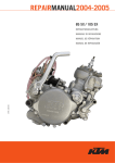
Fig. 1 Cylinder numbering Grasso reciprocating compressors
Legend
1, 2, 3, ...
Cylinder numbers
T
Top view of compressor
M
Motor/Drive end of compressor
O
Oil pump of compressor
OUT OF PRODUCTION
2 AND 3 CYLINDER COMPRESSOR MODELS
Although this manual contains information on the 2, 3,
4, 6, 9 and 12 cylinder compressors, since the 1st
October, 2003, the 2 and 3 cylinder compressors are no
longer in production (single stage and two stage).
NEVER CHANGE POSITIONS!
Never change positions of parts when re-assembling the
compressor. E.g. cylinder liners, suction valves, discharge
valves and relief valves have to be replaced always in the
origional position.
- 10-
Reciprocating Compressors for industrial refrigeration / Series Grasso 12E
SIM0611/v006
1. REPAIR AND OVERHAUL
1. REPAIR AND OVERHAUL
Table of Contents
Section
Title
Page
1.1
INTRODUCTION
11
1.2
EVACUATION/DRYING THE REFRIGERATING SYSTEM
11
1.3
EVACUATION OF THE COMPRESSOR
11
1.4
GENERAL RECOMMENDATIONS
11
1.1
INTRODUCTION
Compressor and plant
All activities described can be carried out without taking
the compressor off its base and without detaching it
from the plant. In case of complete overhaul, it may,
however, be useful to carry this out detached from the
plant in a separate working area, whether or not in a
workshop equipped for this purpose.
Accessories
This chapter only deals with the disassembly and
assembly of a so-called "bare compressor" in standard
design. This implies that, depending on the dismantling
degree, it may be necessary to first completely or
partially remove certain accessories.
It is recommended to distinctly mark the dismounted
accessories or parts of them (for instance oil control lines
and pressure gauge or safety switch lines, transducers,
pressure and temperature sensors, V-belt pulleys and
torsionally-stiff coupling) in order to avoid mistakes at
reassembling.
Tools
For proper performance of the operations, at least the
standard service tools and materials should be available.
Besides, for certain operations additional special
GRASSO tools are required, which can be obtained as a
complete standard service set.
Service Sets
Worn out parts are to be replaced by new parts which
are available in sets with a brief service manual.
General
Although all the assembly and disassembly procedures
shown relate to the two-stage compressor, they are
basically applicable universally to all compressors. If not,
it is explicitly stated in the text.
1.2
EVACUATION/DRYING THE
REFRIGERATING SYSTEM
For evacuation of compressor only, refer to Section 1.3
SIM0611/v006
Procedure to evacuate and to dry a system:
i) STATUS: System is filled with nitrogen and no oil has
been added (oil prevents any trapped moisture from
boiling off).
ii) Verify that all valves in that part of the system to be
evacuated are opened (refer also to the plant
manual).
iii) Connect vacuum pump to the evacuation/purging
valve(s) of the compressor (for location of these
valves refer to the "Product Information" or to a
connection as mentioned in the plant manual and
evacuate the system to approx. 5 mm Hg (=6.6 mBar).
iv) Break vacuum by charging dry nitrogen into the
system.
v) Repeat step iii, 'Connect vacuum pump ...'.
vi) Wait approx. 24 hours.
vii) If pressure has increased (system still contains
moisture), repeat steps iv, vand vi, otherwise,
continue with the "Initial oil charge" procedure.
1.3
EVACUATION OF THE COMPRESSOR
Use always a vacuum pump to evacuate the compressor.
To evacuate the refrigeration system refer to Section 1.2,
Procedure to evacuate the compressor:
i) Switch off main control panel.
ii) Remove main fuses.
iii) Remove the refrigerant by means of a vacuum pump,
via the evacuation/purging valve(s) as prescribed by
local safety regulations. For the location of these
valves refer to the "Product Information".
1.4
GENERAL RECOMMENDATIONS
1. Do not disassemble more compressor parts than is
necessary for the purpose (inspection, repair,
overhaul).
2. Use clean and well-conditioned tools.
3. Make sure that there is a clean and neatly arranged
working area well-equipped to provide temporary
and adequately protected storage of dismantled
components. Preferably use a table or working bench
with a clean, moisture-free and non-scratching
surface.
4. Immediately clean every dismantled part, check it for
wear or damage and oil the machined surfaces of
Reciprocating Compressors for industrial refrigeration / Series Grasso 12E
- 11-
1. REPAIR AND OVERHAUL
bright parts. The oiling is particularly important when
the parts are not to be reassembled until after some
time. Otherwise they will certainly become rusty.
5. The dismantled parts of every cylinder (cylinder liner,
piston, connecting rod, valves) or of other main
components should be kept together separately and
marked if necessary. Thus they can later be replaced
in their original place in the compressor.
6. All major parts that are not beyond repair have to be
checked before reassembly for wear by measuring
them and comparing the outcome with the wear
limits and tolerances given in documentation.
7. Always replace damaged or worn compressor parts
that are beyond repair by new GRASSO standard
spare parts. These parts can always be fitted into the
compressor without previous inspection or
readjustments (if applicable, e.g. valves, connecting
rods, etc.).
8. When fitting any moving parts, it is recommended to
oil all running surfaces.
9. Always use new gaskets, O-rings and locking rings
when reassembling after inspection or repair.
10.Use a torque wrench to tighten the threaded
connections. (Survey of torques for bolts and nuts
refer to Chapter 5)
- 12-
Reciprocating Compressors for industrial refrigeration / Series Grasso 12E
SIM0611/v006
2. DISASSEMBLY
2. DISASSEMBLY
Table of Contents
Section
Title
Page
2.1
REMOVING FLYWHEEL
13
2.2
DISMANTLING SUCTION GAS FILTER
15
2.3
DISMANTLING THE PRESSURE RELIEF VALVE HOUSING
15
2.4
REMOVING DISCHARGE VALVE ASSEMBLY
16
2.5
EXPLANATION CYLINDER LINER VERSIONS
17
2.5.1
REMOVING THE PISTON/CONNECTING ROD ASSEMBLY
17
2.6
REMOVING THE VALVE-LIFTING HOUSING AND THE CYLINDER LINER
19
2.7
DISMANTLING THE ROTARY SHAFT SEAL
20
2.8
REMOVING OIL SUCTION AND OIL DISCHARGE FILTERS
21
2.9
REMOVING OIL PUMP ASSEMBLY
22
2.10
THRUST BEARING
25
2.10.1
DISMANTLING STANDARD THRUST BEARING
25
2.10.2
HEAVY DUTY THRUST BEARING CONSTRUCTION
26
2.10.2.1
DISMANTLING HEAVY DUTY THRUST BEARING
26
2.11
REMOVING CRANKSHAFT, INTERMEDIATE BEARING AND MAIN BEARINGS
27
2.11.1
Introduction
27
2.11.2
Intermediate bearings in 4, 6, 9 and 12 cylinder compressors
27
2.11.3
2 and 3 cylinder compressors (i.e. without intermediate bearing)
28
2.11.4
4, 6, 9 and 12 cylinder compressors (with intermediate bearing)
28
2.11.5
Removing the crankshaft, METHOD A (without auxiliary tools)
29
2.11.6
Removing the crankshaft method B (with auxilary tools)
29
2.11.7
Internal oil connection line
29
2.11.8
Line coupling pieces
29
2.1
REMOVING FLYWHEEL
For many service and repair operations the flywheel or
the V-belt pulley has to be removed.
Fig. 2.1-1
SIM0611/v006
Reciprocating Compressors for industrial refrigeration / Series Grasso 12E
- 13-
2. DISASSEMBLY
S Alternately unscrew the four M12-bolts five rotations
(screwing anticlockwise).
Fig. 2.1-4
Fig. 2.1-2
S Remove the locking disc.
S Remove the locking plate.
S Unscrew the centre M24-bolt five rotations (screwing
anticlockwise).
S Loosen the wheel by alternately tightening the four
M12-bolts clockwise. Keep screwing until the wheel is
entirely loose.
Fig. 2.1-5
S Now slide the wheel or V-belt pulley hanging in the
sling off the compressor shaft.
Fig. 2.1-3
S Remove the four M12 hexagon head bolts.
S Fix a sling on the top of the wheel. Pull the sling in
such a way that the wheel can still move freely on the
shaft.
- 14-
Reciprocating Compressors for industrial refrigeration / Series Grasso 12E
SIM0611/v006
2. DISASSEMBLY
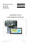
2.2
DISMANTLING SUCTION GAS FILTER
2.3
DISMANTLING THE PRESSURE RELIEF
VALVE HOUSING
Fig. 2.2-1
Legend
1
Cover
2
Spring
3
Filter
S Remove the bolts from the left cover of the suction
S
S
S
S
gas filter housing.
Remove the cover with the pression spring and filter
mounted to it from the housing.
After the circlip ring has been removed from the
centring pin, the filter can be easily removed.
Remove the O-ring from suction gas filter and replace
a suction filter if it is dirty.
NOT FOR 21, 42, 63 and 84 compressors1:
Remove the cover on the right handed side of the
suction gas filter housing in the same way and clean
the inside of the housing.
Fig. 2.3-1 Back pressure dependent relief valve
The LP pressure relief valve housing is mounted against
the cylinder block.
S Unscrew four of the six M12 bolts out of the cylinder
block and remove the bolts.
S Unscrew the two remaining M12 bolts and remove
the housing.
1. Right side cover does not exist for 21, 42, 63 and 84 compressors
SIM0611/v006
Reciprocating Compressors for industrial refrigeration / Series Grasso 12E
- 15-
2. DISASSEMBLY
If there is any doubt about the proper performance of a
pressure relief valve, then the relief valve should be
renewed immediately. When a pressure relief valve
works improperly, discharge gas starts circulating
through the cylinder head, which makes this cylinder
head feel much warmer compared to other cylinder
heads.
In some compressors blind flanges have been fitted at
the connecting opening. There is no need to remove
these blind flanges during normal servicing or repair.
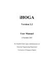
2.4
REMOVING DISCHARGE VALVE
ASSEMBLY
Never test the relief valve by closing the discharge valve
of a running compressor. This will damage the seat of
the relief valve.
Fig. 2.4-1
S Remove dirt and paint particles from the cylinder
Fig. 2.3-2 Back pressure independent relief valve
head studs using a steel brush.
S Oil all studs.
S Remove all M16 bolts from the short studs.
S Release the buffer spring tension by alternately
unscrewing the two nuts on the longer studs.
For regular service it is not necessary to remove the
pressure relief valve from its housing. However, if it has
worked once, it can be dismantled/serviced as described
in this manual.
Fig. 2.3-3 Blind flanges
- 16-
Reciprocating Compressors for industrial refrigeration / Series Grasso 12E
SIM0611/v006
2. DISASSEMBLY
Legend
3
Discharge valve assembly
4
Sinusoidal springs2
5
Suction valve ring
S Remove the cylinder head cover, the buffer spring,
the pressure spring cup1, the discharge valve
assembly with the two or three2 suction valve
sinusoidal springs and the suction valve ring.
2.5
EXPLANATION CYLINDER LINER
VERSIONS
Grasso 12E can have two different cylinder liner versions;
1 Latest version with suction sleeves; from approx
August 2003
2 Olde version with suction holes; Before approx
August 2003
For more details refer to Section 4.5.
2.5.1
REMOVING THE PISTON/CONNECTING ROD
ASSEMBLY
Fig. 2.4-2 Discharge valve assy (From serial number 00081502)
Fig. 2.5-1
S Place an oil drip tray under the service cover that is to
be removed to collect the residual oil in the inclined
crankcase openings.
S Remove the service cover with O-ring opposite the
cylinder under repair.
S In the case of vertical cylinders, remove the opposing
service covers.
Fig. 2.4-3 Discharge valve assy (Up to serial number 00081502
Legend
1
Buffer spring
2
Pressure spring cup
SIM0611/v006
1. Old version of discharge valve model only
2. The number of sinusoidal springs is dependent on refrigerant and/or
operating conditions.
Reciprocating Compressors for industrial refrigeration / Series Grasso 12E
- 17-
2. DISASSEMBLY
Fig. 2.5-4
Fig. 2.5-2
S Rotate the crankshaft in such a way that the big end
of the connecting rod becomes easily accessible.
S Tap up both connecting rod bolts a small amount of
force so that the connecting rod cap can be removed
easily.
S Pull both connecting rod bolts back to their original
places in the connecting rod.
S Move the piston that is to be removed to top position
by rotating the crankshaft by hand.
Fig. 2.5-5
Fig. 2.5-3
S Insert the T-handle (from auxiliary tool kit) into the
S Unscrew the two M16 nuts from the connecting rod
bolts and remove the (double) locking rings.
- 18-
threaded hole at the top of the piston and carefully
pull the piston and the connecting rod out of the
cylinder liner, making sure that the big end of the
connecting rod does not damage the cylinder liner.
Reciprocating Compressors for industrial refrigeration / Series Grasso 12E
SIM0611/v006
2. DISASSEMBLY
The connecting rod cap is marked and belongs to a
specific connecting rod. There is only one way to refit it
onto the connecting rod. Therefore conrod numbers
should always be situated on one side. Keep the
corresponding connecting rod parts together!
In order to able to dismantle the cylinder liner, it is not
necessary to remove the valve-lifting housing.
S Inspect the cylinder liner bore
Measure the bore in three places of the empty and
cleaned cylinder liner, being at the top, in the middle and
at the bottom, and replace if the bore is larger than is
given, or if the honing marks have (partly) disappeared.
2.6
REMOVING THE VALVE-LIFTING
HOUSING AND THE CYLINDER LINER
Fig. 2.6-2
S Place the longer bar1 over two studs of the cylinder
head.
S Insert the threaded rod with nut and washer into this
bar.
S Place the short bar centrally across the bottom of the
cylinder liner.
Screw the threaded rod into this short bar until
the assembly is fully closed.
Now tighten the nut until the cylinder liner is
loose.
Fig. 2.6-1
S Disconnect the oil line on the valve-lifting housing.
S Mark the position of (each) valve-lifting housing on
the corresponding mounting flange.
S Remove the entire housing, including the control
piston in it, by unscrewing the M10 bolts from the
cylinder jacket.
S Check the still mounted lever and carrier disc with
dowel pin (= ø8 mm) for irreparable damage.
Fig. 2.6-3
Remove the auxiliary tools and take out the
cylinder liner by hand.
1. All these parts are included in the auxiliary tool kit ETA.
SIM0611/v006
Reciprocating Compressors for industrial refrigeration / Series Grasso 12E
- 19-
2. DISASSEMBLY
S For cylinder liners with suciont holes only (old
version):
Remove the gasket of the cylinder liner collar,
determine the original thickness of the gasket
(1.0, 1.25 or 1.50 mm) and write down this value
on the corresponding cylinder wall.
2.7
DISMANTLING THE ROTARY SHAFT
SEAL
Fig. 2.7-3
S Place the oil drip tray under the shaft seal housing
and remove the M12 bolts from the shaft seal
housing.
Fig. 2.7-1
S Dismantle and remove the leakage drain from the
bottom of the shaft seal housing.
Fig. 2.7-4
S Slide the shaft seal housing over the shaft journal out
of the bearing cover.
S Take the counter slip ring from the shaft seal housing,
remove the O-rings from the counter slip ring and
from the rear side of the housing.
Fig. 2.7-2
S Remove the drive key from the crankshaft driving
end.
- 20-
Reciprocating Compressors for industrial refrigeration / Series Grasso 12E
SIM0611/v006
2. DISASSEMBLY
Fig. 2.7-7
S Slide the slip ring from the shaft .
Fig. 2.7-5
S Unscrew the three locking screws at the
circumference of the slip ring shaft seal using the M4
allen key from the auxiliary tool kit .
2.8
REMOVING OIL SUCTION AND OIL
DISCHARGE FILTERS
Pictures of oil pump are without the normally fitted oil
charge valve.
It is also possible to remove the oil pump and the filters
mounted to it as a whole. If the filter elements only have
to be inspected or replaced, it suffices to unscrew the
grooved filter nut and the filter housing that has to be
supported by hand, after an oil drip tray has been placed
under it.
Use the special tool key for removing oil filters.
Fig. 2.7-6
S Place two similar screwdrivers behind the slip ring and
carefully push the grips into the direction of the
crankcase until the slip ring is loose.
Do not scratch the crankshaft!
Fig. 2.8-1 Special tool for removing oil filters
Avoid touching the (black) carbon ring (if necessary wear
gloves or rub your hands with oil) and the lapped
counter surface of the ring.
SIM0611/v006
Reciprocating Compressors for industrial refrigeration / Series Grasso 12E
- 21-
2. DISASSEMBLY
Fig. 2.8-4
S In order to remove the entire oil suction filter (left)
Fig. 2.8-2 Oil pump and filter
and/or the oil discharge filter (right), only the two
M10 mounting bolts of each filter have to be
removed.
S Mark the filter housing to prevent interchange!
As both filter housings are identical and can possibly be
interchanged, every filter element is marked with a
colour: - Red for the running-in oil discharge filter which
must be replaced within the first 100 hours with a grey
coloured oil discharge filter. The oil suction filter is
coloured blue.
2.9
REMOVING OIL PUMP ASSEMBLY
S Put an oil drip tray under the pump to collect the
residual oil.
Unscrew the M12 nuts from the studs and slide
the pump as a whole over the studs.
Fig. 2.8-3
- 22-
Reciprocating Compressors for industrial refrigeration / Series Grasso 12E
SIM0611/v006
2. DISASSEMBLY
If required, the oil pump can also be removed with both
oil filters still mounted to it.
On the crankshaft side this hold down disc is provided
with a lapped surface. Damage to this surface as a result
of rough use are very hard to repair and reuse of such a
hold down disc can damage the compressor within a
short time!
Fig. 2.9-1
S Remove the carrier disc which was left behind after
removal of the oil pump.
Fig. 2.9-2
S Remove the now accessible four M10 socket bolts
connecting the hold down disc with the crankshaft.
Carefully remove the hold down disc with the
fitted dowel pin from the crankshaft.
SIM0611/v006
Reciprocating Compressors for industrial refrigeration / Series Grasso 12E
- 23-
2. DISASSEMBLY
- 24-
Reciprocating Compressors for industrial refrigeration / Series Grasso 12E
SIM0611/v006
2. DISASSEMBLY
2.10 THRUST BEARING
2.10.1
DISMANTLING STANDARD THRUST BEARING
Two types of thrust bearings have to be considered
1. Standard
a Bronze, mark 2, (latest version), refer Fig. 2.10-1
b Aluminium (old version), refer Fig. 2.10-2
2. Heavy duty
Fig. 2.10-3
S The released thrust bearing can now be carefully
removed with an allen key (from the shaft seal kit or
auxiliary tool set).
Fig. 2.10-1 Standard bronze thrust bearing, “mark 2”
As the adhesive power behind the thrust bearing has to
be overcome, the ring can suddenly slip off.
Fig. 2.10-2 Old version of standard thrust bearing, aluminium.
SIM0611/v006
Reciprocating Compressors for industrial refrigeration / Series Grasso 12E
- 25-
2. DISASSEMBLY
2.10.2
HEAVY DUTY THRUST BEARING
CONSTRUCTION
In addition to the standard design there is an alternative
"heavy duty" roller thrust bearing available for certain
applications and consists of a twin type roller assembly.
One main bearing for the outward pull of the crankshaft
and a second one for inward push of the crankshaft
during vacuum operation. The total assembly is
pre-loaded by means of springs to ensure proper running
conditions are achieved.
B)
Compressors fitted with roller thrust bearings can be
easily recognised by an external oil overflow line running
from the oil pump to one of the crankcase covers and a
marking on the top of the oil pump. (Compressors fitted
with the standard thrust bearing arrangement have an
internal overflow back to the crankcase and no marking)
Fig. 2.10-5 Heavy duty thrust bearing
2.10.2.1
DISMANTLING HEAVY DUTY THRUST
BEARING
A) Remove external oil line, oil pump and carrier disk
Remove heavy duty thrust bearing
All running surfaces of the washers in contact with the
cylindrical roller thrust bearing and the needle thrust
bearing are hardened and smooth machined. Damages
to these surfaces as a result of rough use are very hard
to repair and reuse of such rings can damage the
compressor within a short time
S Remove the 7 mm. thick housing washer (1) from the
S
S
S
Fig. 2.10-4 External oil line
S Remove the external oil line (1) which is connected
from the top of the oil pump to the service cover.
S .Remove the oil pump. Unscrew the M12 nuts, take
off the washers and slide the oil pump of the M12
studs
Pay attention not to lose the springs or the spring
retainer.
S Remove the carrier disc.
- 26-
S
S
hold down disc (4).
Remove the needle thrust bearing (2) from the hold
down disc (4).
Remove the now accessible four M10 socket bolts (3)
and the hold down disc (4) which is connected to the
shaft washer (5).
Remove the shaft washer (5) from the crankshaft.
Remove the cylindrical roller thrust bearing (6) from
the crankshaft.
The released 1 mm. thick thrust washer (7) can be
carefully removed with a wire hook as shown Fig.
2.10-6.
Reciprocating Compressors for industrial refrigeration / Series Grasso 12E
SIM0611/v006
2. DISASSEMBLY
In case of direct drive, preferably remove the crankshaft
via the pump side.
Fig. 2.10-6 Remove thrust washer with hook (1)
The bearing cover has been equipped with three
round shaped chambers to create space for a wire
hook to grip behind the thrust washer for
removal.
Fig. 2.11-1
2.11.2
INTERMEDIATE BEARINGS IN 4, 6, 9 AND 12
CYLINDER COMPRESSORS
As the adhesive power behind the 1 mm. thick thrust
washer (7) has to be overcome, the ring can suddenly slip
off.
S Remove the spring retainer (8) from the oil pump
housing.
S Remove the springs (9) from the spring retainer(8)
2.11 REMOVING CRANKSHAFT,
INTERMEDIATE BEARING AND MAIN
BEARINGS
2.11.1
INTRODUCTION
S Before starting, the following components must have
been removed:
All discharge valves
All pistons and connecting rods
Shaft seal and key
Oil pump
Thrust bearing
SIM0611/v006
Fig. 2.11-2
S Mark both bearing block parts of each intermediate
bearing so that they can later be refitted in the same
position. For easy reference the crankshaft has been
left out!
Remove both M20 bolts with corresponding
toothed spring washers from the intermediate
bearing support(s) in the crankcase.
It is not necessary to remove the counter weights
from the crankshaft, but on account of the
crankshaft weight, the counter weights may
preferably be dismantled.
Reciprocating Compressors for industrial refrigeration / Series Grasso 12E
- 27-
2. DISASSEMBLY
Remove the bearing cover with the corresponding
O-ring on the pump side. Now the crankshaft of
the 2 and 3 cylinder compressor only rests in the
bearing cover on the driving side.
Assisted by a second person, now carefully
remove the crankshaft from the crankcase
through the opening on the oil pump side.
Put the crankshaft down on a clean place.
If the bearing is only to be inspected, there is no need
to remove the parts mentioned.
2.11.4
Fig. 2.11-3
S Write down the markings of the counterweights
before they are taken off the crankshaft for faultless
replacement later on.
Unscrew both M16 bolts from each
counterweight.
Remove the counterweights with the (double)
locking rings.
2.11.3
2 AND 3 CYLINDER COMPRESSORS (I.E.
WITHOUT INTERMEDIATE BEARING)
S Remove the swivel on top of the bearing cover on the
pump side.
Unscrew all M16 nuts from the studs of the
bearing cover on the pump side.
Screw two M10 (jacking) bolts into the threaded
holes on both sides of the bearing cover.
Tighten these two bolts evenly and alternately
until the bearing cover is loose.
4, 6, 9 AND 12 CYLINDER COMPRESSORS
(WITH INTERMEDIATE BEARING)
S Remove the swivel on top of the bearing cover on the
pump side.
Unscrew all M16 nuts from the studs of the
bearing cover on the pump side.
Screw two M10 (jacking) bolts into the threaded
holes on both sides of the bearing cover.
Tighten these two bolts evenly and alternately
until the bearing cover is loose.
S Remove the bearing cover (and the O-ring) and put it
aside separately.
REMARK: As the 4 and 6 cylinder compressor has only
one intermediate bearing, the crankshaft has
to be supported.
Fig. 2.11-5
S Unscrew all M16 nuts from the studs of the bearing
cover on the driving side.
Tighten the two jacking bolts further until the
bearing cover is loose.
Remove the bearing cover (and the O-ring) and
put it aside separately.
Fig. 2.11-4
- 28-
Reciprocating Compressors for industrial refrigeration / Series Grasso 12E
SIM0611/v006
2. DISASSEMBLY
2.11.5
REMOVING THE CRANKSHAFT, METHOD A
(WITHOUT AUXILIARY TOOLS)
crankshaft can now be easily removed from the
crankcase with assistance from a second person.
With the 4, 6, 9 and 12 cylinder compressor
unscrew the M16 intermediate bearing bolts.
Take both bearing block halves from the
crankshaft and prepare them for inspection by
reassembling them to each other leaving out the
crankshaft.
2.11.7
INTERNAL OIL CONNECTION LINE
Fig. 2.11-6
S Remove the crankshaft of the 4, 6, 9, and 12 cylinder
compressor in steps.
Make use of the intermediate bearings and/or
crank webs and the still mounted counter
weights, for use as supports on the edges of the
crankcase openings.
With the 4, 6, 9 and 12 cylinder compressor,
unscrew the four M16 intermediate bearing bolts.
Remove both bearing block halves from the
crankshaft and prepare them for inspection by
reassembling them to each other leaving out the
crankshaft.
S The crankshaft can be removed more easy by making
use of a simple tool. This method B (with auxiliary
tool) is described below.
2.11.6
Fig. 2.11-8
S Uncouple and remove the internal oil connecting line
and remove the oil line.
2.11.8
LINE COUPLING PIECES
REMOVING THE CRANKSHAFT METHOD B
(WITH AUXILARY TOOLS)
Fig. 2.11-9
S Remove all line coupling pieces from both sides of the
crankcase.
Fig. 2.11-7
S By sliding the long tool (not available from Grasso)
over the shaft end on the pump side and the short
tool over the shaft end on the driving side, the
SIM0611/v006
Reciprocating Compressors for industrial refrigeration / Series Grasso 12E
- 29-
2. DISASSEMBLY
- 30-
Reciprocating Compressors for industrial refrigeration / Series Grasso 12E
SIM0611/v006
3. INSPECTION AND PREASSEMBLY
3. INSPECTION AND PREASSEMBLY
Table of Contents
Section
3.1
Title
Page
PRESSURE RELIEF VALVE ASSEMBLY
31
3.1.1
Back pressure dependent relief valve
32
3.1.2
Back pressure independent relief valve
32
3.2
LUBRICATING OIL PRESSURE REGULATOR
32
3.3
CONTROL OIL PRESSURE REGULATOR
33
3.4
VALVE-LIFTING CONTROL MECHANISM RC12E
33
3.5
DISCHARGE VALVE ASSEMBLY AND SUCTION VALVE
35
3.5.1
DISCHARGE VALVE ASSEMBLIES
35
3.5.1.1
DIFFERENT TYPE OF DISCHARGE VALVE ASSEMBLIES
35
3.5.1.2
DISMANTLING AND INSPECTION DISCHARGE VALVE ASSEMBLY
36
3.5.1.3
PREASSEMBLING DISCHARGE VALVES
36
3.5.2
SUCTION VALVE
36
3.6
PISTON/CONNECTING ROD
37
3.6.1
General
37
3.6.2
Connecting rod
37
3.6.3
Piston
38
3.6.4
Preassembling the piston/connecting rod
38
3.7
CYLINDER LINER AND VALVE-LIFTING MECHANISM
39
3.7.1
CYLINDER LINER WITH SLEEVES AND VALVE-LIFTING MECHANISM
39
3.7.1.1
General
39
3.7.1.2
Preassembling the valve-lifting mechanism
40
3.7.2
CYLINDER LINER (WITH HOLES, OLD VERSION) AND VALVE-LIFTING MECHANISM
41
3.8
OIL PUMP AND OIL FILTERS
42
3.9
MAIN BEARINGS
45
3.10
ROTARY SHAFT SEAL
47
3.11
CRANKSHAFT
48
3.12
THRUST BEARINGS
49
3.12.1
STANDARD BRONZE THRUST BEARING, MARK 2
49
3.12.2
HEAVY DUTY THRUST BEARING
49
3.13
CRANKCASE
49
3.1
PRESSURE RELIEF VALVE ASSEMBLY
General
A defect or malfunctioning pressure relief valve can and
may not be repaired. In these cases a new relief valve has
to be ordered (safety regulation).
Two different types of relief valves can be applied:
1 Back pressure dependent
2 Back pressure independent
SIM0611/v006
Reciprocating Compressors for industrial refrigeration / Series Grasso 12E
- 31-
3. INSPECTION AND PREASSEMBLY
3.1.1
BACK PRESSURE DEPENDENT RELIEF VALVE
5 Slight wear can be remedied with polishing paper.
6 Reassemble all parts into a whole after
inspection/repair.
3.2
LUBRICATING OIL PRESSURE
REGULATOR
Fig. 3.1-1 Back pressure dependent
REMARK: This type of relief valve can be supplied with
different factory settings. Never change
these relief valve(s) from compressor and/or
position.
3.1.2
BACK PRESSURE INDEPENDENT RELIEF
VALVE
Fig. 3.1-2 Back pressure independent
This back pressure dependent pressure relief valve
consists of two major components, the pressure relief
valve housing (1) and the pressure assembly (2). With
this pressure relief valve it is permitted to replace only
the pressure assembly (2) without the valve housing (1).
1 The cause of a malfunctioning pressure relief valve is
usually a minor damage in the teflon seal of the
pressure assembly (2).
2 Check the valve seat in the pressure relief valve
housing (1).
3 In order to inspect this, only the four M12 bolts (3)
have to be unscrewed from the pressure relief valve
housing to remove the pressure assembly (2).
4 If damage or wear of the teflon ring of the pressure
assembly (2) is detected, check whether this can be
remedied by polishing.
- 32-
Fig. 3.2-1 Oil pressure regulators
S The lubricating oil pressure regulator (not equipped
with a groove in the hexagon nut) (see Fig. 3.2-1) is
fitted in the left-hand side of the pump and can be
taken out with the help of a ring spanner or socket
spanner 41, provided that the oil suction filter has
been removed.
Fig. 3.2-2
Table 3.2-1
Legend
1
Cap
2
Housing
3
Pressure spring
4
Ball
5
Circlip ring
6
Set bolt
7
O-ring
8
Alu-ring
Reciprocating Compressors for industrial refrigeration / Series Grasso 12E
SIM0611/v006
3. INSPECTION AND PREASSEMBLY
S Renew O-ring (7) and Alu-ring(8)
All parts forming the regulator do not need wear
inspection, but it is recommended to clean all
(disassembled) regulator parts, to oil them with
compressor oil and to reassemble.
3.4
VALVE-LIFTING CONTROL MECHANISM
RC12E
The pressure can be adjusted with a screwdriver only
during operation.
3.3
CONTROL OIL PRESSURE REGULATOR
Fig. 3.4-1
A) Parts of the valve-lifting housing
S Remove the cover (1) from the housing (6) and
Fig. 3.3-1 Oil pressure regulators
remove the control piston (3) from the housing.
Remove pressure spring (5) with O-ring (4) and
clean the piston.
Clean the control piston bore in the valve-lifting
housing and check this for wear or slight damage
(which may be remedied with polishing paper)
and replace the housing if the bore is over 40.070
mm.
Check the pressure spring and replace it if the
untensioned length is less than 51 mm.
Place the pressure spring and the lubricated piston
with a new O-ring (4) into the housing, mount the
cover with a new O-ring (2) and put it a side to be
reassembled later.
Fig. 3.3-2 Control oil pressure regulator
S The control pressure regulator (equipped with a
groove in the hexagon nut, see lower regulator in Fig.
3.3-1) fitted in the right-hand side of the pump can be
taken out with a ring spanner or socket spanner 41,
provided that the oil discharge filter has been
removed.
S Disassemble, inspect and reassemble as described in
relation to the lubrication oil pressure regulator.
SIM0611/v006
Reciprocating Compressors for industrial refrigeration / Series Grasso 12E
- 33-
3. INSPECTION AND PREASSEMBLY
B)
Parts valve lifting mechanism
Fig. 3.4-2
S If the lever (1) does not easily fit inside the (firmly
tightened) set screw (2) (on the side of every cylinder
head), slight wear or damage of the lever shaft and
in the bore of the still fitted set screw may be
remedied with polishing paper after dismantling the
disc (3) and lever (1).
In the case of irreparable damage or wear, both
the set screw and lever have to be replaced.
- 34-
Reciprocating Compressors for industrial refrigeration / Series Grasso 12E
SIM0611/v006
3. INSPECTION AND PREASSEMBLY
3.5
3.5.1
DISCHARGE VALVE ASSEMBLY AND
SUCTION VALVE
DISCHARGE VALVE ASSEMBLIES
3.5.1.1
DIFFERENT TYPE OF DISCHARGE VALVE
ASSEMBLIES
Following different types of discharge valve assemblies
are possible;
Fig. 3.5-1 OPTION 1; E3-2; Discharge valve assembly NH3 (From serial
number 04010001)
Fig. 3.5-3 OPTION 3; M2.2; Discharge valve assembly (Up to serial
number 00081502)
Table 3.5-1 Legend discharge valve assemblies
Legend
1
Valve seat
6
Nut
2
Central bolt
7
Stroke limitor
3
Damper rings, valve rings and
springs
8
Double locking ring
Fig. 3.5-2 OPTION 2; E3-3 Discharge valve assembly for halocarbons,
type E (From serial number 00081502)
SIM0611/v006
Reciprocating Compressors for industrial refrigeration / Series Grasso 12E
- 35-
3. INSPECTION AND PREASSEMBLY
3.5.1.2
S
S
S
S
S
S
DISMANTLING AND INSPECTION DISCHARGE
VALVE ASSEMBLY
Insert an allen key into center bolt (1).
Remove the M16 nut (6) from the central bolt (1), the
double locking ring (8), the discharge valve stroke
limitor (7), the sets of damper rings, sinusoidal springs
and valve rings (3).
Thoroughly clean all valve parts and the valve seat
(2).
Inspect the valve plate (2) for damange, wear or
scoring. Replace the valve plate if one of the seats is
damaged or when the seat is wider than 1.2 mm.If
during this inspection the stroke limitor appears to
have made contact with the piston, the connecting
rod bearings have to be checked as well; the
clearance should then be determined.
Inspect the PEEK valve and damper rings for
discoloured, cracks or other signs of damage. Always
replace the rings when they are close to the
maximum allowed running hours.
Inspect the discharge valve stroke limitor (7) and the
valve ring guide cams on the bottom side of the
stroke limitor for wear.
In case of wear (shifting of valve rings and valve
springs) or damage due to another cause, the
discharge valve stroke limitor has to be renewed.
3.5.1.3
PREASSEMBLING DISCHARGE VALVES
Fig. 3.5-5 Preassembling discharge valves
S Place each damper ring in their respective grooves of
S
S
S
S
the discharge valve stroke limitor, then the sinusoidal
springs (with the convex side facing the stroke
limitor) and finally the discharge valve rings into the
stroke limitor.
Place the combined valve plate (2) over the stroke
limitor.
If necessary, adjust the clamped valve rings and valve
springs with a screwdriver until all cams of the stroke
limitor touch the valve seat.
Fit the (M16) central bolt with a nut and a new
double locking ring.
Tighten this bolt/nut joint to the torque as
given(Section 5.1).
Fig. 3.5-4 Discharge valve, sinoidal spring
S Replace the discharge valve sinusoidal springs when
they are damaged/discoloured and when the
untensioned height 'h' is less than as given ( Table
3.5-2)
To check leakage of the discharge valves, a leak test after
4 running hours of the compressor is strongly
recommended. (Refer Section 4.14)
3.5.2
SUCTION VALVE
Table 3.5-2 Minimum untensioned heights
Sinusoidal spring
DISCHARGE VALVE ASSY
diameter
h min
(mm)a
1
NH3
E3-2
smallest
5.5
largest
8.5
2
Halocarbons
from serial
no. 00081502
E3-3
smallest
2.8
medium
5.5
Fig. 3.5-6 Suction valve, sinoidal spring
largest
8.5
S Replace the suction valve sinusoidal springs when
smallest
2.5
medium
3.5
largest
5.5
3
Up to serial
no. 00081502
M2.2
a. Refer Fig. 3.5-4
- 36-
they are damaged or discoloured and when the
untensioned height 'h' is less than 9.6 mm.
S Inspect the cylinder liner for wear of the seats.
Replace the cylinder liner if one of the seats is
damaged or when the seat is wider than 2.2 mm.
Reciprocating Compressors for industrial refrigeration / Series Grasso 12E
SIM0611/v006
3. INSPECTION AND PREASSEMBLY
3.6
PISTON/CONNECTING ROD
3.6.1
3.6.2
CONNECTING ROD
GENERAL
Fig. 3.6-3
S Assemble the bearing shells and the connecting rod
Fig. 3.6-1
S Place the assembly upside down on the working
bench and remove one circlip ring from the gudgeon
pin bore.
Fig. 3.6-2
cap into a whole.
Tighten the nuts on the connecting rod bolts to
the torque given(Section 5.1).
Measure the bore of the clamped bearing with an
inside micrometer and replace if it is larger as the
value given(Table 5.2-1).
Check the bearing bush (for the LP cylinders) in
the small end of the connecting rod for wear or
damage.
With an inside micrometer measure the bore of
the still fitted bearing bush and replace if it is
larger as the value given(Table 5.2-1).
Insert a new bearing bush by lowering the
non-heated bearing bush into the small end of the
connecting rod which has been heated to approx
80 °C.
Check the condition of the double-row needle
bearing (for the HP cylinders) and replace if
necessary.
Insert the needle bearing as described for the
bearing bush.
S Heat the piston to approximately 80 °C
S NEVER HEAT WITH OPEN FLAME! Pouring a little
spirit into the piston and lighting it works just as well.
Push the gudgeon pin out of the piston.
Check the (cooled) gudgeon pin for wear and
measure the outer diameter using an outside
micrometer and replace the pin if the diameter is
smaller than the value given(Table 5.2-1).
SIM0611/v006
Reciprocating Compressors for industrial refrigeration / Series Grasso 12E
- 37-
3. INSPECTION AND PREASSEMBLY
3.6.3
PISTON
Fig. 3.6-6
Fig. 3.6-4
S Check the gap in each piston ring by placing it in an
S Remove the two piston rings and oil scraper ring
using the appropriate piston ring pliers.
Check the piston grooves for burrs, notch effects
and cracked or broken grooved edges.
unworn part of the cylinder liner. These unworn parts
can be found at about 10 mm from the bottom of the
cylinder liner. The maximum gap may not exceed 2.1
mm.
3.6.4
PREASSEMBLING THE PISTON/CONNECTING
ROD
Never use new piston rings in combination with a worn
out cylinder liner.
Fig. 3.6-5
S Roll each piston ring and oil scraper ring in the
corresponding groove around the piston to trace
parts that have become wedged. This can be
remedied, for example, by using a smooth file.
Also check the rest of the piston for wear or
damage.
Fig. 3.6-7 Pistion
Legend
T
Top
CHR
Chromium-plated
S If the piston rings and oil scraper ring are no longer
on the piston, fit them in the sequence as shown.
Never mix old and new rings together. When placing
the rings, pay attention to the word 'TOP' on each
ring.
- 38-
Reciprocating Compressors for industrial refrigeration / Series Grasso 12E
SIM0611/v006
3. INSPECTION AND PREASSEMBLY
Place the connecting rod into the piston and slide
the oiled gudgeon pin through the piston into the
connecting rod onto the still fitted circlip ring.
Fig. 3.6-8
S Clean the connecting rod and blow out the oil
passageway in the connecting rod.
When replacing the bearing bushes or needle
bearings, heat the small end of the connecting rod
to approximately 80 °C.
Insert the bearing bush (for LP cylinders) or
respectively the needle bearing, distance ring and
needle bearing (for HP cylinders) into the small
end of the connecting rod.
Check whether the needle bearings project
equally on both connecting rod ends.
Let the connecting rod cool off in ambient air.
Fit the bearing shells in both connecting rod parts.
Due to the raised fixing cams only one building-in
position is possible.
Fig. 3.6-10
S Lock the gudgeon pin with the other circlip ring.
3.7
CYLINDER LINER AND VALVE-LIFTING
MECHANISM
General
Compressors older than approx. August 2003 can be
applied with cylinder liners having suction HOLES. These
cylinder liners can be re-newed for cylinder liners having
suction SLEEVES, however in combination with the
proper suction and discharge valves(Consult Grasso). The
latest version of cylinder liners are those with suction
sleeves, however the re-assembling procedure is
described below for both types.
3.7.1
3.7.1.1
CYLINDER LINER WITH SLEEVES AND
VALVE-LIFTING MECHANISM
GENERAL
Fig. 3.6-9
S Heat the piston to approximately 80 °C, DEFINITELY
NOT IN OPEN FIRE!
S Pouring a little spirit into the piston and lighting it
works just as well.
Degrease the gudgeon pin and oil it.
Check that the gudgeon pin fits properly into the
connecting rod.
SIM0611/v006
Reciprocating Compressors for industrial refrigeration / Series Grasso 12E
- 39-
3. INSPECTION AND PREASSEMBLY
Also check the cam ring on the inside.
After truing up the inner and/or outer surfaces,
check that the cam ring moves smoothly around
the cylinder liner.
3.7.1.2
PREASSEMBLING THE VALVE-LIFTING
MECHANISM
Fig. 3.7-1 Cam ring
S Place the cylinder liner upside down on the working
bench, remove the 2 hexagon bolts (2) from the cam
ring (1). Now the cam ring can be removed from the
cylinder liner.
Fig. 3.7-3
S Before starting, oil all parts with compressor
Fig. 3.7-2
S If necessary, remove the locking rings (1) of the 8
push pins (2) and the washers (3) and springs( 4)
S Clean all parts
Check the suction valve ring seat in the cylinder
liner collar for damage or locally worn honing
tracks.
It is not necessary to check the cylinder liner
diameter if the honing tracks in the cylinder liner
bore are still intact. Irregularities can be carefully
eliminated with abrasive paper.
Check the outer surface of the cylinder liner for
damage and eliminate slight damages with
abrasive paper.
- 40-
lubricating oil.
Place the cylinder liner with the collar on the
working bench.
Mount the 8 push pins (sphere side must face to
the cam ring!) (1) through the holes of the lowest
guide ring (2) of the cylinder liner, fit the washers
(3) and springs (4) and subsequently insert the
push pins through the holes of the upper guide
ring (5)and the holes of the cylinder liner collar.
Place the locking rings (6) on the push pins so the
washer will be between the spring and locking
ring.
Build the cam ring with the cams facing the
suction sleeves onto the cylinder liner(refer Fig.
3.7-1). Mount 2 hexagon bolts with the spacers
into the cam ring.
Check the cam ring manually for proper
operating.
Reciprocating Compressors for industrial refrigeration / Series Grasso 12E
SIM0611/v006
3. INSPECTION AND PREASSEMBLY
3.7.2
CYLINDER LINER (WITH HOLES, OLD
VERSION) AND VALVE-LIFTING MECHANISM
A) General
Fig. 3.7-6
S Clean all parts
Check the suction valve ring seat in the cylinder
Fig. 3.7-4
S Place the cylinder liner upside down on the working
bench, remove the locking spring (1) and
subsequently slide the cam ring (2) from the cylinder
liner.
B)
liner collar for damage or locally worn honing
tracks.
It is not necessary to check the cylinder liner
diameter if the honing tracks in the cylinder liner
bore are still intact. Irregularities can be carefully
eliminated with abrasive paper.
Check the outer surface of the cylinder liner for
damage and eliminate slight damages with
abrasive paper.
Also check the cam ring on the inside.
After truing up the inner and/or outer surfaces,
check that the cam ring moves smoothly around
the cylinder liner.
Preassembling the valve-lifting mechanism
Fig. 3.7-5
S If necessary, remove the locking rings (1) of the 8
push pins (2) and the washers (3) and springs (4).
Fig. 3.7-7
S Before starting, oil all parts with compressor
lubricating oil.
Place the cylinder liner with the collar on the
working bench.
SIM0611/v006
Reciprocating Compressors for industrial refrigeration / Series Grasso 12E
- 41-
3. INSPECTION AND PREASSEMBLY
Mount the 8 push pins (1) through the holes of
the lowest guide ring (2) of the cylinder liner, fit
the washers (3) and springs (4) and subsequently
insert the push pins through the holes of the
upper guide ring (5) and the holes of the cylinder
liner collar.
Place the locking rings (6) on the push pins so the
washer will be between the spring and locking
ring.
Slide the cam ring with the cams facing
downwards onto the cylinder liner.
3.8
OIL PUMP AND OIL FILTERS
A) General
Fig. 3.8-1
S Place the pump on the working bench and unscrew
the eight M6 fixing bolts (1) in the pump cover out of
the housing and remove the washers (2) and the
pump cover (3) with the integrated pump element.
Remove the O-ring (4).
Fig. 3.7-8
S Insert the locking spring in the groove of the cylinder
liner. During mounting align the gap in the locking
spring with the guide pin of the cam ring then rotate
the spring aprox. 1/4 turn around the liner.
Check that the push pins drop just beneath the
suction valve ring when resting on the lower part
of the cam ring.
Fig. 3.8-2
S Remove the pump gear (5) from the crown wheel (6)
of the pump element/bearing assembly.
S Remove all plugs with alu-washers from the pump
housing as well as the O-rings which seal the internal
oil passageways.
Clean the packing face of the pump housing and
the pump cover and if still present: Remove the
lubricating oil and control pressure regulators.
Clean the pump housing with a non-fibrous cloth
and the internal oil passageways of the pump
housing with compressed air.
- 42-
Reciprocating Compressors for industrial refrigeration / Series Grasso 12E
SIM0611/v006
3. INSPECTION AND PREASSEMBLY
Renew the pump element/bearing assembly in
C)
Inserting a new pump element
case of irreparable damage or malfunctioning of
the oil pump.
B)
Removing the pump element/bearing assembly
Fig. 3.8-3
S Place the pump housing with the pump cover fixing
face in central position and pointing downwards
under a press (take precautionary measures that the
fixing pin, indicated with arrow! does not break).
Place an auxiliary bush (B) with an outer diameter
øD < 60mm and an inner bore ød > 45 mm over
the crown wheel shaft. In this position the pump
element/bearing assembly can easlily be pressed
out with a hydraulic press.
S Clean all pump parts and remove possible sharp
edges and/or burrs.
Check the carrier lug for wear.
Check the teeth of both pump elements for
broken or worn teeth.
Replace the entire pump element if at least one of
the pump elements shows irreparable wear.
Minor damage may be eliminated.
SIM0611/v006
Fig. 3.8-4
S Ensure that the bore and the contact face in the
pump housing are clean and oiled.
S Place the pump housing with the bearing cover fixing
face in central position and pointing downwards,
using the pump cover(3)(!), under a press.
S Position the pump element/bearing assembly with
the oil passageway (= notched groove in the running
surface) at 12.00 h (visible via the small bores inside
crown wheel surface.
S Carefully press the pump element into the housing
with the cover until the contact face has been clearly
reached.
Reciprocating Compressors for industrial refrigeration / Series Grasso 12E
- 43-
3. INSPECTION AND PREASSEMBLY
Check that pump element can be rotated by hand!
The shorter control pressure regulator has a groove on
the hexagon nut. The longer lubricating oil pressure
regulator does not have a groove.
Fig. 3.8-5 Carrier disc
Remove the carrier disc from the crankshaft
journal and check the condition of the slot and the
holes of the carrier disc.
D) Reassembling the oil pump
Fig. 3.8-7 Pump detail
S Slide the pump gear (5) onto the shaft (7) of the
Fig. 3.8-6
S Lightly oil all parts mentioned below before
reassembly!
Insert into the housing: new O-rings in the internal
oil passageways, the plugs provided with new
alu-washers, the lubricating oil pressure regulator
(1) in the left-hand part of the housing and the
control pressure regulator (2) in the right-hand
part of the housing.
- 44-
pump cover (3).
Place the pump housing on its side and insert the
preassembled pump cover element provided with
a new O-ring in such a way that the fixing pin (P)
fits into the corresponding hole.
S Tighten the eight M6 bolts (8) provided with washers
(9) in the pump housing to the torque given in table
“Survey of torques for bolts and nuts“(Chapter 5).
Check that the pump rotates smoothly; if this is
not the case, the pump element is not pressed far
enough inside the oil pump housing.
Place the preassembled pump in a separate clean
area to be mounted onto the bearing cover later.
Reciprocating Compressors for industrial refrigeration / Series Grasso 12E
SIM0611/v006
3. INSPECTION AND PREASSEMBLY
E)
Filter elements
Filter elements can also be replaced when the filter
housings are still mounted to the compressor.
Use special tool to remove oil filters (refer )Section 2.8
S In order to reach the oil suction filter or oil discharge
filter element, only the lower housing half has to be
removed by supporting the housing and unscrewing
the grooved nut.
Fig. 3.8-9
Fig. 3.8-8 Oil suction and oil discharge filter
Pay attention to the residual oil in this filter
Remove the O-rings (2 and 4) and the seal (3).
Clean both filter housings (1 and 5) and the
internal (connecting) passageways.
Insert each filter in the corresponding filter
housing and reassemble them with a new set of
seals1, a washer (3) and new O-rings (2 and 4).
bottom
For a total inspection both the upper filter
housings can be removed from the pump housing
by unscrewing both M10 bolts.
Remove the filters as described (Section 2.8)
Whilst the the oil suction filter element is
cleanable, it shoul be replaced in case of damage
or serious pollution.
The red 'running-in' oil discharge filter element is
to be replaced by a grey one after 100 running
hours.
Renew a polluted grey-marked oil discharge filter
element.
In order to avoid damaging the seals, the filter housing
(5) should not revolve together with the grooved nut
(6).
REMARK: After having dis-assembled the discharge
filter element, check this for contamination,
in particular for the presence of aluminium
and/or white metal slide-bearing particles
which would require further investigation in
other parts of the compressor. In this case,
regularly check the oil quality by means of an
oil analysis.
3.9
MAIN BEARINGS
A) General
1. Only available as set under Ref. No. 09.90.030.
SIM0611/v006
Reciprocating Compressors for industrial refrigeration / Series Grasso 12E
- 45-
3. INSPECTION AND PREASSEMBLY
bush out of the bearing cover.
Draw, for instance with a felt pen, a longitudinally
line and over the full length on the outside of the
new bearing bush above the centre of the oil
chamber.
Fig. 3.9-1 41
S Check both main bearing bushes, while they are in
their respective bearing covers, for worn out white
metal inner lining.
Replace the bush(es) if the inner lining shows
abnormal wear and also if the bore is over 90.16
mm.
Especially check those crankshaft parts rotating in
the bearing covers. Eliminate slight damage using
fine polishing paper.
Check the thrust face (see arrow 'A') on the collar
of the bearing bush on oil pump side for wear and
replace it if one of the oil grooves has virtually
disappeared.
B)
Fig. 3.9-3 43
S Oil the bearing bush and place it with the internal
chamfer facing upward and above the bore in the
bearing cover in such a way that the oil passageway
is in the centre of the locking pin.
Slowly press the bearing bush (using a hydraulic
press) into the bearing cover, making sure that
the bearing bush is not displaced.
Bearing cover on pump side;
Preassembling the bearing covers
Bearing cover on driving side:
Fig. 3.9-4 44
When the bearing bush requires replacement, proceed
as follows:
S Push or press (using a hydraulic press) the old bearing
bush out of the bearing cover.
Fig. 3.9-2 42
S When replacing a bearing bush, proceed as follows:
S Push or press (using a hydraulic press) the old bearing
- 46-
Reciprocating Compressors for industrial refrigeration / Series Grasso 12E
SIM0611/v006
3. INSPECTION AND PREASSEMBLY
Draw a longitudinal line, for instance with a felt
pen, on the outside of the new bearing bush from
the centre of recess 'A' (to the left of oil chamber
'B') as far as the collarless end.
3.10 ROTARY SHAFT SEAL
Avoid touching the carbon part! Preferably rub your
hands with oil or wear gloves.
Fig. 3.9-5 Bearing cover with mounted splash guard
S Oil the bearing bush and position it above the bore in
the bearing cover, so that the line drawn with the
(felt) pen is in the centre of the locking pin.
Slowly press the bearing bush (using a hydraulic
press) into the bearing cover, making sure that
the drawn line is not displaced, in order for the
locking pin on the left-hand side (projecting 3 mm
above the bearing cover) to be pressed entirely
into recess 'A'.
Fig. 3.10-1
S Remove the O-ring (3a) from the counter slip ring (3)
and the O-ring (2a) in the rotating ring (2).
Check the sliding surfaces of the counter slip ring
(3) and the rotating ring (2) for wear or damage.
Clean the housing (1) and all other parts.
When one of the sliding surfaces is affected,
replacement of both parts is required.
Renew all O-rings (1a, 2a and 3a).
Fig. 3.9-6 46
S Inspect the intermediate bearing(s) for visual wear
and for possible scoring of the white metal inner
lining and collar bearings.
Assemble the intermediate bearing(s) with the
stamped-in numbers on one side and tighten the
intermediate bearing bolts.
Measure the inside diameter and replace it when
it is over 90.14 mm.
SIM0611/v006
Fig. 3.10-2
S Renew the entire shaft seal in the case of damage or
wear of the slip ring.
Reciprocating Compressors for industrial refrigeration / Series Grasso 12E
- 47-
3. INSPECTION AND PREASSEMBLY
3.11 CRANKSHAFT
A) General
Fig. 3.11-3 51
S Check the diameters of the shaft journals and shaft
ends with an outside micrometer in at least 2
directions and dead square to the measuring surface.
Here measure 'A' should be at least 89.933 mm
and measure 'B' 89.945 mm.
Should these measurements show that the shaft
diameter(s) is (are) beyond the tolerance limits
and there is any doubt about the serviceability of
this crankshaft, then the shaft should be replaced.
Fig. 3.11-1 49
S Only with 2 cylinder compressors, remove the spacer
(compensating mass) from the crankshaft and
reassemble both halves into a whole, separately from
the crankshaft.
B)
Preassembling the crankshaft
Fig. 3.11-2 50
S Thoroughly clean the entire crankshaft:
Check whether the axially fitted oil passageways
- 48-
in the crankshaft are unobstructed by cleaning
them with compressed air or a brush.
In order to be sure that the passage of lubricating
oil within the crankshaft is unobstructed, unscrew
the socket head screws (locked with centre
punches) out of the crankshaft webs.
Remove the dirt accumulated in the oil
passageway (in the case of damage to bearings
white metal particles) with a 6 mm bar.
Brush and blow out the crankshaft again until all
oil passageways are unobstructed.
After cleaning, reassemble all oil passageway
sealing bolts (socket head screws) and lock them
with centre punches.
Fig. 3.11-4 52
S In the case of 4, 6, 9 and 12 cylinder compressors,
place the shells of the intermediate bearings into the
bearing block(s).
Oil both bearing shells well and fit the
intermediate bearing(s) on the crankshaft
(intermediate bearing halves with stamped-in
numbers on one side).
Tighten the four M16 bolts to the torque
given.(refer Chapter 5)
Check that the intermediate bearing(s) freely
revolve(s) around the crankshaft.
Reciprocating Compressors for industrial refrigeration / Series Grasso 12E
SIM0611/v006
3. INSPECTION AND PREASSEMBLY
3.12.2
HEAVY DUTY THRUST BEARING
Fig. 3.12-2 Heavy duty thrust bearing
S Clean all thrust bearing parts. Check all running
Fig. 3.11-5 53
S In the case of a 2 cylinder compressor, fit the spacer
onto the crank web on the driving side using two M8
bolt/nut joints and tighten these to the torque as
given.(refer Chapter 5)
3.12 THRUST BEARINGS
Besides a standard mounted thrust bearing, a heavy duty
thrust bearing can be mounted (optional)
3.12.1
surfaces which are in contact with the cylindrical
roller thrust bearing and the needle thrust bearing
for (ir)regular wear and other damage such as pits,
marks or scratches.
Replace the complete heavy duty thrust bearing
set when the rollers, needles or running surfaces
show signs of wear.
3.13 CRANKCASE
STANDARD BRONZE THRUST BEARING,
MARK 2
Refer Section 2.10
Fig. 3.13-1
Fig. 3.12-1 Standard bronze thrust bearing; refer also Fig. 2.10-2
S Clean the thrust bearing and check the lapped
running surface on the bronze side for (ir)regularly
worn oil grooves and for material deposits.
Replace this thrust ring if it shows signs of wear
and when the thickness is less than 5.50mm.
SIM0611/v006
S Thoroughly clean the crankcase interior and dry it
with a non-fibrous cloth.
Inspect all exterior packing faces and remove
possible residual packing particles.
Thoroughly blow through all connections on the
inside and on the outside.
Clean the sight glass.
Reciprocating Compressors for industrial refrigeration / Series Grasso 12E
- 49-
3. INSPECTION AND PREASSEMBLY
Do not forget to remove the packing remains
from the flanges of the main connections of the
compressor!
Fig. 3.13-2
S Remove the oil return plug from the lowest landing
of the cylinder jackets for the LP cylinders {see left
plug in Fig.}
Inspect the return plugs, clean them and tighten
them after refitting.
The plug for the HP cylinders {see right plug in
fig.} does not need inspection and can therefore
remain fitted.
- 50-
Reciprocating Compressors for industrial refrigeration / Series Grasso 12E
SIM0611/v006
4. REASSEMBLING
4. REASSEMBLING
Table of Contents
Section
Title
Page
4.1
CRANKSHAFT, MAIN BEARINGS AND INTERMEDIATE BEARING
52
4.1.1
Bearing cover driving side
52
4.1.2
Assembly procedure of 2 and 3 cylinder compressors
52
4.1.3
ASSEMBLY PROCEDURE 4, 6, 9 AND 12 CYLINDER COMPRESSORS
52
4.1.4
Pump side
52
4.1.5
Bearing cover oil pump side (with two lugs):
53
4.1.6
Standard thrust bearing
53
4.1.7
Heavy duty thrust bearing
54
4.1.8
Measuring the axial crankshaft play
55
4.1.9
Procedure for 4, 6, 9 and 12 cylinder compressors
55
4.1.10
Assembling counter weights
56
4.2
OIL PUMP
56
4.3
OIL SUCTION FILTER, OIL DISCHARGE FILTER, LUBRICATING OIL PRESSURE REGULATOR AND CONTROL OIL PRESSURE
REGULATOR
57
4.3.1
Oil discharge filter
57
4.3.2
Oil suction filter
57
4.3.3
Lubricating oil pressure regulator (without groove)
57
4.3.4
Control oil pressure regulator (with groove)
57
4.4
VALVE-LIFTING CONTROL MECHANISM
57
4.5
CYLINDER LINER
59
4.5.1
CYLINDER LINER (LATEST VERSION, WITH SLOTS)
59
4.5.2
CYLINDER LINER (OLD VERSION, WITH HOLES)
61
4.6
PISTON/CONNECTING ROD ASSEMBLY
62
4.7
DETERMINING THE PISTON CLEARANCE
63
4.8
SUCTION/DISCHARGE VALVE ASSEMBLY
63
4.9
ROTARY (SLIP RING) SHAFT SEAL
65
4.10
SUCTION GAS FILTER
66
4.11
PRESSURE RELIEF VALVE ASSEMBLY
67
4.12
OIL FILLING
67
4.13
MOUNTING FLYWHEEL
68
4.14
DISCHARGE VALVES, LEAKAGE TEST PROCEDURE
69
SIM0611/v006
Reciprocating Compressors for industrial refrigeration / Series Grasso 12E
- 51-
4. REASSEMBLING
4.1
CRANKSHAFT, MAIN BEARINGS AND
INTERMEDIATE BEARING
4.1.1
4.1.3
ASSEMBLY PROCEDURE 4, 6, 9 AND 12
CYLINDER COMPRESSORS
BEARING COVER DRIVING SIDE
Fig. 4.1-3
S With assistance and using auxiliary tools, insert the
Fig. 4.1-1
S Place a new O-ring on the inner side of the bearing
cover.
crankshaft (with/without counterweights1) through
the crankcase opening on the pump side into the
crankcase. The crankshaft now rests on the
intermediate bearing block(s).
Remove the auxiliary tools, clean the shaft
journals and oil them.
4.1.4
PUMP SIDE
Fig. 4.1-2
S Place the bearing cover on the driving side in such a
way that the hole in the lug of the bearing cover is
opposite the internal oil passageway pipe.
Then slide the bearing cover over the crankcase
studs.
Screw all M16 nuts provided with washers on the
studs and tighten them alternately and crosswise
to the torque given in (Chapter 5).
Fig. 4.1-4
S Place a new O-ring on the pipe of the internal oil
passageway.
4.1.2
ASSEMBLY PROCEDURE OF 2 AND 3
CYLINDER COMPRESSORS
S Insert the crankshaft (with/without counterweights)
through the crankcase opening on the oil pump side
into the bearing cover.
1. For mounting the counter weights see further on in this chapter "Assembling
counter weights".
- 52-
Reciprocating Compressors for industrial refrigeration / Series Grasso 12E
SIM0611/v006
4. REASSEMBLING
Fig. 4.1-7
Fig. 4.1-5
4.1.5
BEARING COVER OIL PUMP SIDE (WITH TWO
LUGS):
S Place a new O-ring on the inner side of the bearing
cover.
Place a new O-ring on both pipes of the internal
oil passageway Fig. 4.1-4.
S Screw all M16 nuts provided with washers on the
studs.
S Finally tighten the nuts alternately and crosswise to
the torque given(Chapter 5).
Check that the crankshaft rotates freely.
4.1.6
STANDARD THRUST BEARING
Fig. 4.1-6
S Place the cover in such a way that the holes in each
lug of the bearing cover are opposite the pipes of the
internal oil passageways and slide the bearing cover
over the crankcase studs.
SIM0611/v006
Fig. 4.1-8 Standard thrust bearing; refer also Fig. 2.10-2
S Fit the oiled thrust ring with the oil grooves directing
outwards on the crankshaft on oil pump side in such
a way that the locking pin in the bearing cover fits
into the hole in this thrust ring surface.
Reciprocating Compressors for industrial refrigeration / Series Grasso 12E
- 53-
4. REASSEMBLING
Pos. 1, 2, 4, 5, 6 and 7 can be mounted together in any
crankshaft angle
S Fit the oiled 1 mm. thick thrust washer (7) on the
S
S
S
Fig. 4.1-9
S Check that the crankshaft boss is still clean and oiled.
Fit the hold down disc onto the crankshaft boss,
S
using the four M10 socket head screws with the
torque given(Chapter 5).
Check that the crankshaft rotates freely.
4.1.7
HEAVY DUTY THRUST BEARING
The reassembling of the heavy duty thrust bearing is split
into two parts, the heavy duty thrust bearing itsself and
the oil pump.
S
1st step; Heavy duty thrust bearing
S Check whether all components are clean, including
the inside of the bearing cover and crankshaft on oil
pump side.
crankshaft on oil pump side.
The thrust washer (7) can be used on both sides.
Fit the oiled cylindrical roller thrust bearing (6) on the
crankshaft on oil pump side.
The cylindrical roller thrust bearing (6) can be used
on both sides.
Fit the oiled shaft washer (5) on the crankshaft on oil
pump side. The shaft washer if recessed to fit exactly
around the crankshaft.
Fit the oiled hold down disc (4) into the shaft washer
(5), using the four M10 socket head screws (3) with
the torque given(Chapter 5).
Check that the crankshaft rotates freely.
Fit the oiled needle thrust bearing (2) on the hold
down disc (4).
The needle thrust bearing (2) can be used on both
sides.
Mate the oiled 7 mm. thick housing washer (1)
against the needle thrust bearing (2).
The housing washer (1) must be mated with its
running surface against the needle thrust bearing
(2), it can not be used on both sides.
2nd step; oil pump for heavy duty thrust
bearing
S Place the carrier disc (10) on the hold down disk (4).
The chamber of the slot of the carrier disc (10)
must face the crankshaft.
Check the crankshafts top surface on oil pump side for
having installed the closed M12 plug, without orifice.
Position the slot of the carrier disc (10) in vertical or
horizontal position by rotating the crankshaft
S Place 2 new O-rings around the oil inlet- and outlet
holes at the bearing cover (11).
S Check that the oil pump is clean.
S Place the oiled spring retainer (8) in the pump
S
S
Fig. 4.1-10 Heavy duty thrust bearing
S
S
- 54-
housing counter bore.
The opening of the holes should be pointed to the
outside of the oil pump housing.
Insert the oiled springs (9) in the holes of the spring
retainer (8).
Place a new O-ring on the inner side of the fully
pre-assembled oil pump.
Slide the oil pump over the studs of the bearing
cover.
Position the carrier lug of the pump element with the
slot in the carrier disc.
Reciprocating Compressors for industrial refrigeration / Series Grasso 12E
SIM0611/v006
4. REASSEMBLING
Pay at all times attention not to dislodge the
4.1.9
springs (9) or the spring retainer (8).
S Push the oil pump as far as possible towards the
bearing cover and screw the M12 nuts with washers
on the studs.
The oil pump cannot be pushed fully against the
bearing cover, because of the springs and will only
seat correctly when the nuts are tightened
Check all springs to be present and in place.
S Reinstall the external oil line. It is connected from the
top of the oil pump to the service cover.
PROCEDURE FOR 4, 6, 9 AND 12 CYLINDER
COMPRESSORS
4.1.8
MEASURING THE AXIAL CRANKSHAFT PLAY
Procedure for 2 and 3 cylinder compressors
Fig. 4.1-12
S Measure the axial play proceeding in the same way as
Fig. 4.1-11
S For this measurement a magnet (clock) gauge with
for the 2 and 3 cylinder compressors.
Position the intermediate bearing block(s) and fit
handtight the 2 sets of toothed spring washers
and the M20 bolts in the cross frame.
Check that the crankshaft rotates freely.
Subsequently, firmly tighten the bearing block(s)
after the intermediate bearing(s) has(ve) been
adjusted in accordance with the drawing
(measure "=" + 0.5 mm)(Fig. 4.1-12).
Further tighten the intermediate bearing bolts to
the torque given(Chapter 5).
an extended gauge can be set up on the bearing
cover.
Remove a stud and screw in the M12 eye bolt.
Screw another eye bolt into the threaded hole on
the crankshaft.
Pull out the crankshaft and set the gauge on 0.00
(zero).
Push the crankshaft inwards and check/write
down the axial play on the gauge.
For every compressor the play is determined between
0.05 and 0.85 mm.
Contact the service department of Grasso if the axial
play is not within the tolerance limits.
Fig. 4.1-13
S If there is no clock gauge available, the axial play in
situ of the collar bearing can also be measured with
the help of feeler gauges. Here again the axial play is
measured by the difference between the pulled out
and pushed in crankshaft (see also measuring
procedure with clock gauge).
SIM0611/v006
Reciprocating Compressors for industrial refrigeration / Series Grasso 12E
- 55-
4. REASSEMBLING
4.1.10
ASSEMBLING COUNTER WEIGHTS
The chamber of the slot of the carrier disc must face the
crankshaft.
Position the slot of the carrier disc in vertical or
horizontal position by rotating the crankshaft.
S Place a new O-ring on the inner side of the fully
pre-assembled oil pump.
Slide the oil pump over the studs of the bearing
cover.
Fig. 4.1-14
S Fit the counterweights with new locking rings and
bolts onto the crankshaft if dismantled.
Pay attention to numbers and marks!
Counterweights are not interchangeble!
S Fit the double locking rings in the proper position!
S Tighten the bolts with a torque wrench to the torque
given(Chapter 5).
4.2
Fig. 4.2-2
Position the carrier lug of the pump element with
the slot in the carrier disc.
Push the oil pump fully against the bearing cover
OIL PUMP
and screw the M12 nuts with washers on the
studs.
Tighten all nuts evenly and crosswise to the torque
given.
Fig. 4.2-1
S Place the carrier disc on the hold down disc.
- 56-
Reciprocating Compressors for industrial refrigeration / Series Grasso 12E
SIM0611/v006
4. REASSEMBLING
4.3
OIL SUCTION FILTER, OIL DISCHARGE
FILTER, LUBRICATING OIL PRESSURE
REGULATOR AND CONTROL OIL
PRESSURE REGULATOR
4.3.1
OIL DISCHARGE FILTER
Fig. 4.3-2
S Install the lubricating oil pressure regulator with a
new aluminium ring on the left-hand side of the
pump.
Finally fit the cap nut handtight on the regulator
using a new alu-ring.
REMARK: Final adjustment of a reassembled
lubricating oil pressure regulator can be
done during compressor operation. This
adjustment procedure is described in the
Installation and Maintenance Manual.
Fig. 4.3-1
After the first 100 operating hours the red-marked
discharge filter has to be replaced by a grey-marked filter
element!
S Fit the preassembled (red1/grey) marked discharge
filter using the two M10 bolts with washers on the
right-hand side of the pump.
Tighten the bolts to the torque given(Section 5.1).
4.3.2
OIL SUCTION FILTER
S Fit the preassembled (marked blue) suction filter
using the two M10 bolts with washers on the
left-hand side of the pump.
Tighten the bolts to the torque given(Section 5.1).
4.3.3
LUBRICATING OIL PRESSURE REGULATOR
(WITHOUT GROOVE)
If not built in yet;
4.3.4
CONTROL OIL PRESSURE REGULATOR (WITH
GROOVE)
S Install the control pressure regulator with a new
aluminium ring on the right-hand side of the
pump.Fig. 4.3-2
Finally fit the cap nut handtight on the regulator
using a new alu-ring.
REMARK: Final adjustment of a re-assembled control
oil pressure regulator can be done during
compressor operation. This adjustment
procedure is described in the Installation and
Maintenance Manual.
4.4
VALVE-LIFTING CONTROL MECHANISM
Assembling dowel pin in carrier disc
1. Always fit a new red-marked oil discharge filter element into a modified plant.
SIM0611/v006
Reciprocating Compressors for industrial refrigeration / Series Grasso 12E
- 57-
4. REASSEMBLING
Fig. 4.4-1
S Press the dowel pin (7) perpendicular into the carrier
disc (4).
Fig. 4.4-2
Pin location in the carrier disc depends on the
position of the valve lifting housing on to the
cylinder wall.
Assembling set screw and lever (in case the
set screw has been removed/replaced):
Fig. 4.4-3
S Screw the set screw (2) in to the threaded bore of the
S Prior to mounting the carrier disc the free space
mounting flange and subsequently the nut (3)
handtight on the set screw (2).
Place the shaft of the lever (1) into the bore of the
set screw.
Lever adjustment:
between cylinder liner and lever must be set to
between0,5 -1,5 mm. This is the distance between the
lever front side and inner side of the lowest
supporting ring in the cylinder jacket which can be
adjusted by turning the set screw.
After adjusment screw down the nut (4),
subsequently carrier disc (5) and mount socket
screw (7, screw tight to the torque setting as given
(Section 5.1) with locking ring (6).
Assembling valve-lifting housing:
- 58-
Reciprocating Compressors for industrial refrigeration / Series Grasso 12E
SIM0611/v006
4. REASSEMBLING
Fig. 4.4-4
S Place O-ring (1) and mount the valve lifting housing
Fig. 4.5-2 Use compressor oil to oil the O-ring location
(2) with built-in piston in its original position to the
flange of the cylinder jacket and fit the four
M10-bolts (4) with washers (3).
Tighten the bolts to the torque given (Section
5.1).
Connect the control pressure oil line to the
housing.
REMARK: After assembling the valve lifting housing,
the lever is in part load situation.
4.5
CYLINDER LINER
General
Compressors older than approx. August 2003 had
cylinder liners with holes to allow suction gas to pass
through. These liners can be exchanged for the later
execution having slots but only in combination with the
corresponding suction and discharge valves (consult
Grasso for advice).
The re-assembly procedure for both types is given below.
4.5.1
Fig. 4.5-3 Fit the O-ring
CYLINDER LINER (LATEST VERSION, WITH
SLOTS)
Fig. 4.5-1 Cylinder housing with hydraulic actuated lever mounted
Fig. 4.5-4 O-ring fitted
SIM0611/v006
Reciprocating Compressors for industrial refrigeration / Series Grasso 12E
- 59-
4. REASSEMBLING
Fig. 4.5-5 Positioning cylinder liner (refer also Fig. 4.5-6)
Table 4.5-1 Legend
Top view cylinder liner
A, B, C
Parallel lines
p
valve lifting pin
q
location pin, refer to Fig. 4.5-6
LS
Long stud
Fig. 4.5-7 Fit the cylinder liner
Check whether the inserted cylinder liner is positioned
properly by comparing it with the other cylinder liners
that were assembled earlier. Check the valve lifting
action with compressed air. Make sure that the cylinder
liner does not rotate!
Fig. 4.5-6 Positioning cyliner liner (refer also Fig. 4.5-5)
S Fix the cam ring through the slots of the cylinder liner
with location pin of the auxiliary toolkit(refer to Fig.
4.5-5 and Fig. 4.5-6) .
S Position the pressure pins of the cylinder liner in line
with the centre of the long cylinder head studs(refer
to Fig. 4.5-5 and Fig. 4.5-6)
S Insert the cylinder liner carefully as far as possible into
the cylinder jacket.
The guide pin must locate in the fork of the lever of
the valve lifting mechanism.
S Check this by rotating the carrier disc of the valve
lifting mechanism.
There must be only a very limited play on this
mechanism.
Fig. 4.5-8 Fit the cylinder liner
S Place the short bar1 on the upper cylinder liner collar
and the long bar over 2 cylinder head studs.
S Fix the long bar with two M16 nuts and place a steel
disc on the threaded hole in the lower bar to protect
the threaded hole from damaging.
S Screw the long M24 bolt into the long bar and
tighten it turning clockwise until the cylinder liner is
fully seated in the inner landing of the cylinder jacket.
S Remove the auxiliary tools.
1. Parts of the auxiliary tool kit.
- 60-
Reciprocating Compressors for industrial refrigeration / Series Grasso 12E
SIM0611/v006
4. REASSEMBLING
A pressure pin (Pos. 2) is now in line with the
guide pin of the cam ring (Pos 3)
S Mark (Pos 1) the second bridge between the suction
gas opening and the pressure pin (Pos 2)
Insert the cylinder liner push bolt (Pos. 5, part of
the auxiliary tool kit) through hole (Pos. 6; 6th
hole) of the suction gas openings in the cylinder
liner. Ensure that it locates in the corresponding
recess (Pos. 8) in the cam ring (Pos. 7)
REMARK: The cylinder liner push bolt (Pos. 5) has to be
inserted through the 6th suction gas
opening, counted from the mark (Pos. 1)
Position the marking (Pos 1) in line with the centre
of the long cylinder head stud (Pos. 4, sketch B).
Fig. 4.5-9 Top view, suction valve with slots
4.5.2
CYLINDER LINER (OLD VERSION, WITH
HOLES)
REMARK: Prior to mounting the cylinder liner, first
position the valve lifting-control mechanism.
S Examine the thickness of the gasket which was
originally placed on the lower landing of the cylinder
jacket and under the cylinder liner collar.
Select a new gasket of the same thickness, being
1, 1.25 or 1.5 mm.
Check that the gasket face of the cylinder jacket is
still clean and place the greased gasket into the
landing.
Write down the thickness of the gasket on the
outside of the cylinder jacket.
Fig. 4.5-11
Press the cylinder liner as far as possible into the
cylinder jacket.
Fig. 4.5-10
S To ensure that the guide pin (3) of the cam ring(Pos.
7) locates in the fork of the lever, proceed as follows:
Turn the cam ring (Pos. 7) to part load position
(pressure pins up)
SIM0611/v006
Fig. 4.5-12
Reciprocating Compressors for industrial refrigeration / Series Grasso 12E
- 61-
4. REASSEMBLING
Place the short green bar1 on the upper cylinder
liner collar and the long green bar over 2 cylinder
head studs.
Fix the long bar with two M16 nuts and place a
steel disc on the threaded hole in the lower bar to
protect the threaded hole from damaging.
Screw the long M24 bolt into the long bar and
tighten it turning clockwise until the cylinder liner
is fully seated in the inner landing of the cylinder
jacket.
Remove the auxiliary tools.
REMARK: Check that the inserted cylinder liner is
positioned properly by comparing it with the
other cylinder liners that were assembled
earlier. Check the valve lifting action with
compressed air. Make sure that the cylinder
liner does not rotate!
Fig. 4.6-2
4.6
PISTON/CONNECTING ROD ASSEMBLY
S Insert the piston/connecting rod assembly into the
cylinder liner.
Lower it very carefully until the ring compression
bush strikes the cylinder liner and after that slowly
push on until the piston is almost entirely located
inside the cylinder liner.
Check that the connecting rod properly embraces
the crankshaft journal. If so, push through to the
crankshaft journal and check that the bearing
shell in the connecting rod has not been displaced.
Fig. 4.6-1
S Slide the connecting rod bolts into the big end of the
connecting rod (make sure that the flat side is
positioned correctly!).
Place the bearing shells into the connecting rod
cap.
Oil baring shells, piston and piston rings.
Slide the ring compression bush2 with the
chamfered end pointing downwards over the
connecting rod, the piston and the oil scraper ring
and piston rings.
Oil and set the relevant crankshaft journal in the
uppermost position of the cylinder centre.
Screw the T-handle (from the auxiliary tool kit)
into the threaded hole of the piston.
Fig. 4.6-3
S Slide the corresponding connecting rod cap over the
connecting rod bolts.
Fit both MF16 nuts with new (double) locking
rings on the connecting rod bolts and tighten to
the torque given.
1. Parts of the auxiliary tool kit.
2. Parts of the auxiliary tool kit.
- 62-
Reciprocating Compressors for industrial refrigeration / Series Grasso 12E
SIM0611/v006
4. REASSEMBLING
Screw the M24 push bolt into the long bar and
after that revolve the crankshaft two or three
times.
Fit the connecting rod parts with the machine codes on
one side.
Determining the piston clearance according to Section
4.7, is required for cylinder liners with holes (old version)
only.
4.7
DETERMINING THE PISTON CLEARANCE
Fig. 4.7-3
S Remove all measuring aids and measure the thickness
Fig. 4.7-1
S Place a solid 2 mm thick lead or tin soldering wire
which has been shaped to fit into the threaded hole
of the piston and laid parallel with the crankshaft or
gudgeon pin.
of the flattened wire. This thickness, which is equal to
the clearance, should be at least 1.05 mm and at most
1.45 mm. If the measuring result is beyond these
limits, it is necessary to remove the piston/connecting
rod again and replace the sealing ring under the
cylinder liner collar by a thicker or thinner one,
according to whether the clearance was too small or
too large.
4.8
SUCTION/DISCHARGE VALVE
ASSEMBLY
S Place the suction valve ring on its seat in the cylinder
liner collar.
Fig. 4.7-2
S Oil the discharge valve assembly and place it on the
cylinder liner.
Place the bar from the auxiliary tool kit on the
studs as well as on the discharge valve centre.
Screw two M16 nuts on the studs .
Fig. 4.8-1 Top view piston
S Place the sinusoidal springs with the convex side
pointing upwards on the suction valve ring.
REMARK: During the assembly the sinusoidal springs in
SIM0611/v006
Reciprocating Compressors for industrial refrigeration / Series Grasso 12E
- 63-
4. REASSEMBLING
inclined cylinders can fall out of the cylinder
liner. This can be prevented by placing the
sinusoidal springs in such a way on the valve
ring that the springs touch the valve ring at
the highest and the lowest point in the
inclined cylinder liner.
Fig. 4.8-4 Top view of discharge valve assy (new version)
Fig. 4.8-2 Top view of discharge valve assy (new version)
Fig. 4.8-5 Top view of discharge valve assy (old version)
S For old version only; Place the oiled pressure spring
cup on the discharge valve assembly.
Fig. 4.8-3 Top view of discharge valve assy (old version)
S Place the preassembled discharge valve assembly on
the sinusoidal springs of the suction valve.
Clean the sealing edge of the cylinder head cover
and also the edge on the cylinder head itself.
Rub both packing faces and the studs with grease.
Fig. 4.8-6 Top view buffer spring (old version)
S For old version only; Subsequently, fit the buffer
- 64-
Reciprocating Compressors for industrial refrigeration / Series Grasso 12E
SIM0611/v006
4. REASSEMBLING
spring which has to be prevented from tipping by a
steel strip placed against the two studs.
S Insert a new gasket into the cylinder cover groove
and slide the cylinder head cover over the studs on
the buffer spring.
4.9
ROTARY (SLIP RING) SHAFT SEAL
Fig. 4.9-1 40
S In the case of new parts, check that the protective foil
Fig. 4.8-7 Top view cylinder cover
Remove the strip.
Screw two M16 nuts on the two long and oiled
studs.
has been removed.
Avoid touching the contact faces of these parts;
slightly rub your hands with oil or wear gloves.
Especially inspect the crankshaft part where the
O-ring moves.
Remove all (rubber) deposit by sanding or
polishing.
Oil all parts with compressor lubricating oil, as well
as the crankshaft part in situ of the shaft seal.
Slide the slip ring part over the crankshaft and
push through until the rear side is positioned
against the crankshaft boss.
Fig. 4.8-8 Top view cylinder cover
Tighten these two nuts alternately to the torque
given(Section 5.1).
After that, fit the other nuts in the same way.
Fig. 4.9-2 41
S Lock the slip ring on the crankshaft by tightening the
three grub screws with an allen key1. (Torque refer
Section 5.1)
1. Part of the auxiliary tool kit.
SIM0611/v006
Reciprocating Compressors for industrial refrigeration / Series Grasso 12E
- 65-
4. REASSEMBLING
Fig. 4.9-3 42
S Insert the counter slip ring with the O-ring into the
shaft seal housing.
Place a new O-ring into the groove of the cleaned
shaft seal housing.
Mount the shaft seal housing (only one mounting
position is possible) onto the crankcase.
S Check that the crankcase is clean and dry and,
subsequently, fit all crankcase covers with new
O-rings.
4.10 SUCTION GAS FILTER
Fig. 4.10-1
Fig. 4.9-4 43
S Place a new gasket into the groove of the suction gas
S Place the M12 nuts and tighten them alternately
filter cover.
Slide the preassembled cover of the suction gas
filter assembly into the housing in such a way that
the centring profile around the filter fits into the
fixed centring edge.
S Screw the eight bolts into the housing and tighten
them to the torque given(Section 5.1).
crosswise to the torque given.
Screw the nipple coupling for the oil leakage drain
line into the bottom of the shaft seal housing and
then the drain line.
- 66-
Reciprocating Compressors for industrial refrigeration / Series Grasso 12E
SIM0611/v006
4. REASSEMBLING
4.11 PRESSURE RELIEF VALVE ASSEMBLY
Fig. 4.12-1 Shaft seal housing
Fig. 4.11-1 Relief valves
Legend
1
Back pressure dependent
2
Back pressure independent
Refer to the valve position table (Section 5.7) for the
location of pressure relief valves.
S Place a new O-ring in (each) pressure relief valve
housing.
Put the pressure relief valve housing into the
proper mounting position (only one mounting
position is possible!) against the cylinder jacket.
Screw the six M12 bolts into the cylinder jacket
and tighten them evenly and crosswise to the
torque given(Section 5.1).
4.12 OIL FILLING
Use clean or fresh original oil only!
Fig. 4.12-2 Oil filters and location oil charge valve (A); not shown!
Oil discharge filter:
Remove all oil filling plugs and fill the corresponding
components with the amount of oil given(Table
4.12-1).
Fit the oil filling plugs with new aluminium rings.
Fit the other nipples and couplings and tap the
key into the crankshaft key way.
S The following components have to be filled with oil
before starting up via the oil charge valve, mounted
on the oil pump, refer Fig. 4.12-2:
Crankcase
Shaft seal housing(Fig. 4.12-1)
Oil pump
Oil discharge filter
Oil lubrication circuit
S Oil suction filter(Fig. 4.12-2 ,left filter): Charge
through the filling openings or prelubricating valves
(if present) on the top of the filter housing.
SIM0611/v006
Table 4.12-1 Quantity of oil
QUANTITY OF OIL TO BE FILLED (IN dm3)
Number of
cylinders
2
3
Shaft seal
housing incl.
Oil
Oil
internal circuit of filters pump
crankshaft
Crankcase
7.8
0.63
4
0.72
6
0.73
9
0.83
21.7
12
0.93
28.7
1.5
each
Reciprocating Compressors for industrial refrigeration / Series Grasso 12E
0.5
13.6
14.7
- 67-
4. REASSEMBLING
4.13 MOUNTING FLYWHEEL
Fig. 4.13-3
Fig. 4.13-1
S Screw three (3) M12-bolts fully into the flywheel hub.
S Place the flywheel on the crankshaft using a
suspension gear with sling.
Fig. 4.13-4
S Tighten the central M24-bolt with a torque wrench to
the torque given(Section 5.1).
Fig. 4.13-2
S Place the locking disc and screw the centre bolt as far
as possible into the crankshaft.
- 68-
Reciprocating Compressors for industrial refrigeration / Series Grasso 12E
SIM0611/v006
4. REASSEMBLING
Fig. 4.13-5
S Lock the central bolt with locking plate, together
with the fourth M12 bolt.
4.14 DISCHARGE VALVES, LEAKAGE TEST
PROCEDURE
A leak test after 4 running hours of the compressor is
strongly recommended;
S Stop compressor
S Immediately close the discharge stop valve and
record the discharge pressure (must be at least 6 bar)
S Measure the time it take for the discharge pressure to
fall to 3 bar. (decrease from 6 to 3 bar)
If equalizing time is less than 60 seconds, all the
discharge valves have to be checked.
SIM0611/v006
Reciprocating Compressors for industrial refrigeration / Series Grasso 12E
- 69-
4. REASSEMBLING
- 70-
Reciprocating Compressors for industrial refrigeration / Series Grasso 12E
SIM0611/v006
5. MISCELLANEOUS
5. MISCELLANEOUS
Table of Contents
Section
Title
Page
5.1
SURVEY OF TORQUES FOR BOLTS AND NUTS
71
5.2
WEAR LIMITS AND TOLERANCES
73
5.3
REQUIRED SERVICE TOOLS AND MATERIALS
75
5.4
GRASSO SPECIAL TOOLS AND AIDS GRASSO 12E
75
5.5
FITTING INSTRUCTIONS FOR PIPE COUPLINGS AND DOUBLE LOCKING RING
77
5.6
MASS OF SEPARATE COMPONENTS AND COMPRESSORS
77
5.7
RELIEF VALVE POSITIONS
77
5.1
SURVEY OF TORQUES FOR BOLTS AND
NUTS
Table 5.1-1
Item
Threaded connection
Thread size
Torque in
N.m.a
1
Bearing cover nuts (both sides)
M16
120
2
Coupling bearing cover on pump side
G1/4”
tightened
3
Shaft seal housing nuts
M12
40
4.1
Oil pump housing bolts
M12
40
4.2
Pump element bolts
M6
7
5
Connecting rod bolts
MF16x1.5
100
6
Gudgeon pin locking bolt
M12
40
7
Valve-lifting housing bolts
M10
35
8
Coupling of the control line valve-lifting housing
G1/8”
tightened
9
Discharge valve (centre bolt)
M16
120
10
Cylinder head nuts
M16
120
11
Cylinder liner tie bolt - nut
M6
---
12
Sight glass flange bolts
M6
7
13
Crankcase side cover bolts
M12
80
14
Pressure relief valve cover bolts
M12
80
15
Pressure relief valve assembly mounting bolts
M12
80
16
Oil discharge filter bolts
M10
35
16
Oil suction filter bolts
M10
35
18
Suction filter housing bolts 2, 3 and 4 cyl. compressor
M12
40
19
Suction filter housing bolts 6, 9 and 12 cyl. compressor
M16
120
20
Bearing block bolts
M16
120
21
Intermediate bearing block bolts
M20
tightened
22
Counterweight bolts
M16
120
23
Crankshaft spacer ring bolts
M8
17.5
24
Standard and heavy duty thrust bearing (pressure piece) socket head
screws
M10
35
SIM0611/v006
Reciprocating Compressors for industrial refrigeration / Series Grasso 12E
Remarks
- 71-
5. MISCELLANEOUS
Item
Threaded connection
Thread size
Torque in
N.m.a
25
Shaft seal (locking) screws
M4
handtight
26
Socket head screw of disc/lever
M5
5.5
27
Coupling leakage drain shaft seal
G1/8”
tightened
28
Oil splash plate bolts
M6
7
29
Sealing plug
G1/4”
tightened
30
Sealing plug
G1/2”
tightened
31
Hand nut suction/discharge filter
M90x3
handtight
32
Threaded rod auxiliary tool
M12
---
33
Lubricating oil pressure regulator - hexagon
M27
tightened
34
Control oil pressure regulator - hexagon
M27
tightened
35
Crankshaft sealing plugs
M8
centre punch
36
Non-return valve in cylinder liner collar
M22
tightened
37
Tapered plug in cylinder liner collar
G1/4”
tightened
38
Push bolt from auxiliary tools
M24
---
39
Pulley puller for shaft seal
M8
---
40
Foundation bolts
M20
tightened
41
Drive coupling bolts
42
Hub securing bolts (4x)
M12
tightened
43
Hub securing (centre) bolt
M24
400
44
Shaft seal - Crankshaft
M6
15 - 18.3
Remarks
refer to service instreuction
00.87.537
a. 1 N.m = 0,102 kgf.m = 0,738 lbf.ft
- 72-
Reciprocating Compressors for industrial refrigeration / Series Grasso 12E
SIM0611/v006
5. MISCELLANEOUS
5.2
WEAR LIMITS AND TOLERANCES
Not only the wear limits determine whether a part is to
be replaced, but moreover the condition of the part;
have the honing or grinding tracks of precision machined
butting or running faces not been worn off irregularly,
are there any visible discolouring of material, has the
roundness remained correct and are there any signs of
glazing. All these wear factors make a part virtually
unserviceable, even if this part remains within its wear
limits.
Table 5.2-1 Wear limits and tolerances
Item
Description of part
Ref.
Limits (mm)
Remarks
1
Main bearing bush pump side
20.38.110
max. inside diam. 90+0,16
When fitted
2
Main bearing bush driving side
20.38.102
max. inside diam. 90+0,16
When fitted
3
Bearing bush small end of the connecting rod
11.46.640
max. inside diam. 40+0,14
When fitted
4
Bearing shell big end of the connecting rod
20.38.140
max. inside diam. 90+0,14
When fitted
5
Crankshaft (main bearing and crankshaft journal)
22.39.....
min. outside diam. 90-0.07
6
Crankshaft (intermediate bearing)
22.39.....
min. outside diam. 90-0.05
7
Crankshaft (axial play)
22.39.....
min. 0.05 / max. 0.85
When fitted
8
Cylinder liner
23.18.010
max. inside diam. 160+0.12
When fitted
9
Gudgeon pin
24.70.040
min. outside diam. 40-0.00
10
Piston rings
09.74.163
max. gap 2+0.1
11
Control pressure piston for valve lifting
12
Control pressure piston housing
27.70.012
max. inside diam. 40+0.07
13
Spring valve lifting housing
11.31.332
min. 51
14
Lever
27.70.112
min. outside diam. 14-0.25
15
Set screw
11.16.112 /
20.70.136
max. inside diam. 14+0.05
When fitted
16
Intermediate bearing
11.44.890
max. inside diam. 90+0.14
When fitted
17
Pivot disc
----------------- /
20.38.106
min. thickness 5.50
18
Buffer spring
11.31.181
max. 115, min. 110
SIM0611/v006
Measured in non-scored part of cylinder liner
27.70.670 / min. outside diam. 40-0.08
20.70.134
Length
Reciprocating Compressors for industrial refrigeration / Series Grasso 12E
- 73-
5. MISCELLANEOUS
- 74-
Reciprocating Compressors for industrial refrigeration / Series Grasso 12E
SIM0611/v006
5. MISCELLANEOUS
5.3
REQUIRED SERVICE TOOLS AND
MATERIALS
Description
Grasso special tool kit TA
In order to properly carry out the disassembly, inspection
and assembly procedures described in this manual, the
service engineer should possess the following tools,
measuring equipment and aids.
Vacuum pump
Centre punch
Circlip pliers
Hammer (steel)
Table 5.3-1
Hammer (soft)
-Spanners:
Description
Ring spanners and socket
spanners (metric):
8-10 (2x)
-13-14-17-19-24-27-30-32-36-41
Hexagon socket head
spanners (metric):
8-13-10-17
Torque spanners (metric)
19-24-30-36
Pin-face wrench (metric) for
shaft seal
M4
Pair of pliers
Lead or tin soldering wire 2
mm
for measuring piston clearance
Polishing paper
Polishing (compound) paste
Misc:
Inside micrometer of 50-100
mm
Outside micrometer of 0-50
mm
Remove split pin valve-lifting
mechanism
Loctite
Inside micrometer of 0-50
mm
-Measuring equipment:
various service activities
(two) Screwdrivers (small)
e.g. for removing shaft seal
Screwdiver (large)
removing key
Abrasive linen
Silicon grease
Wire brush
Outside micrometer of
50-100 mm
Piston ring pliers
Depth micrometer of 0-50
mm
Grease
Vernier gauge of 10"
Self-made (crankshaft)
auxiliary tool
Feeling gauges of 0.05-1.00
mm
Auxiliary tools for shaft seal
removing and inserting
crankshaft
Steel strip
Magnetic gauge with
extended plunger
support buffer spring
Oil drip tray
Tube brush ø10 mm
cleaning crankshaft oil
passageways
Bar ø6 mm
cleaning crankshaft oil
passageways
Compressed air device
cleaning e.g. crankshaft oil
passageways
Hydraulic press
Heater approx. 80 °C
5.4
removing and inserting
connecting rod bearings
GRASSO SPECIAL TOOLS AND AIDS
GRASSO 12E
Certain operations which requires fitting and removing
pistons and cylinder liners can be substantially be
simplified by using special tools and aids which are
obtainable as standard auxiliary tool kit under ref. no.
20.70.010. A list of the content of this standard kit is
given below.
SIM0611/v006
Reciprocating Compressors for industrial refrigeration / Series Grasso 12E
- 75-
5. MISCELLANEOUS
- 76-
Reciprocating Compressors for industrial refrigeration / Series Grasso 12E
SIM0611/v006
5. MISCELLANEOUS
5.5
FITTING INSTRUCTIONS FOR PIPE
COUPLINGS AND DOUBLE LOCKING
RING
5.6
MASS OF SEPARATE COMPONENTS
AND COMPRESSORS
Table 5.6-1
Mass
(kg)
Description
Bearing cover drive end (assembly)
22.2
Bearing cover oil pump end
22.5
Oil pump housing, complete with
filters
28.2
Cylinder liner assy
11.7
Intermediate bearing assy
10.2
number of
cylinders
-
2
54.0
3
57.5
4
66.5
6
81.0
9
124.0
12
145.0
Crankshaft
Fig. 5.5-1 Pipe couplings
Relief valve assy
13.0
Remarks
Mind the remaining oil
still present when
removing the oil pump
housing!
With the assistance of a
second person and using
auxiliary tools the
crankshaft can be
removed or fitted.
Careful when removing!
The full weight is
released all at once.
For weights of bare shaft compressor and flywheel, refer to Product
Information (ED).
Fig. 5.5-2 Double locking ring
A) Preparation
S Saw off the pipe at right angles.
5.7
RELIEF VALVE POSITIONS
S Deburr and clean the pipe end.
S Oil thread, taper and clamping sleeve (facilitates
fitting).
S In bends, the minimum length of the straight pipe
end must be twice the height of the union nut.
A = Coupling threaded piece
B = clamping sleeve
C = Union nut
D = Pipe
B)
Fitting
S Slide union nut and clamping sleeve on the pipe
(mind the assembling sequence).
S Press pipe against stop and tighten union nut by
S
S
S
S
hand.
Tighten a further half a turn (clamping sleeve is about
to grip).
Slack the union nut and retract pipe from stop by 2 3 mm.
Tighten 3/4 - 1 turn (ridges now penetrate into pipe).
On reassembly, only tighten up the union nut.
SIM0611/v006
Fig. 5.7-1 Relief valve; back pressure independent
Reciprocating Compressors for industrial refrigeration / Series Grasso 12E
- 77-
5. MISCELLANEOUS
Fig. 5.7-2 Relief valve; Back pressure dependent
- 78-
Reciprocating Compressors for industrial refrigeration / Series Grasso 12E
SIM0611/v006
5. MISCELLANEOUS
Table 5.7-3 Relief valves R404A
Relief valve positions per cylinder number (LP = Low Pressure,
HP = High Pressure, B = Blind flange):
NH3
1
2
3
4
5
6
7
8
9
10
11
12
Type of compr.
Type of compr.
Table 5.7-1 Relief valves NH3
Relief valve positions per cylinder number (LP = Low Pressure,
HP = High Pressure, B = Blind flange):
R404A
1
2
LP
2
LP
3
LP
3
LP
4
LP
4
LP
6
LP
6
LP
9
B
LP
21
LP
31
LP
42
LP
51
LP
3
9
LP
12
2
4
LP
12
B
HP
HP
HP
HP
5
6
LP
31
LP
42
LP
51
LP
LP
HP
72
LP
HP
72
LP
HP
93
LP
102
HP
B
HP
B
B
84
LP
93
LP
LP
102
12
LP
HP
63
B
11
HP
HP
HP
10
HP
LP
LP
9
HP
63
84
8
LP
LP
21
7
HP
LP
HP
LP
HP
LP
HP
LP
Type of compr.
Table 5.7-2 Relief valves R134a
Relief valve positions per cylinder number (LP = Low Pressure,
HP = High Pressure, B = Blind flange):
R134a
1
2
LP
3
LP
4
LP
6
LP
2
3
9
4
B
12
5
6
LP
31
LP
42
LP
51
LP
12
LP
HP
HP
LP
HP
LP
11
HP
LP
93
10
HP
72
LP
9
HP
63
84
8
LP
LP
21
7
102
SIM0611/v006
HP
B
HP
B
HP
LP
HP
LP
Reciprocating Compressors for industrial refrigeration / Series Grasso 12E
- 79-
5. MISCELLANEOUS
- 80-
Reciprocating Compressors for industrial refrigeration / Series Grasso 12E
SIM0611/v006
6. APPENDIX; Product Information (PI)
6. APPENDIX; Product Information (PI)
Table of Contents
Section
6.1
Title
MAIN DIMENSIONS AND SPACE REQUIREMENTS
SIM0611/v006
Reciprocating Compressors for industrial refrigeration / Series Grasso 12E
Page
83
- 81-
6. APPENDIX; Product Information (PI)
- 82-
Reciprocating Compressors for industrial refrigeration / Series Grasso 12E
SIM0611/v006
6. APPENDIX; Product Information (PI)
6.1
MAIN DIMENSIONS AND SPACE
REQUIREMENTS
Table 6.1-1
COMPRESSOR 212
TYPE
312
412
612
912
1212
2112
3112
4212
5112
6312
7212
8412
9312
10212
Length
A
977
987
1307
1377
1792
2182
987
1307
1377
1377
1792
1792
2182
2182
2182
Width
B
1077 1171
1077
1171
1171
1171
1171
1110
1171
1171
1171
1171
1171
1171
1171
Height
C
881
884
931
931
931
931
876
931
931
931
931
931
931
931
SIM0611/v006
931
D
876
848
876
848
848
848
848
876
848
848
848
848
848
848
848
E
881
688
884
871
871
871
871
864
871
871
871
871
871
871
871
F
316
522
316
548
560
950
786
790
795
795
795
795
795
795
795
G
0
406
0
189
189
189
648
745
688
688
688
688
688
688
688
H
530
541
548
548
560
560
950
950
950
J
509
903
913
913
1315
1315
1705
1705
1705
K
149
224
163
163
163
163
163
163
163
L
195
108.5
195
195
195
195
195
195
195
M
406
331
406
406
406
406
406
406
406
217
217
217
N
205
205
205
205
217
217
205
205
205
205
217
217
O
295
295
625
685
1075
2x732.5
295
625
685
685
1075
1075
P
345
345
345
345
369
369
345
345
345
345
369
369
Reciprocating Compressors for industrial refrigeration / Series Grasso 12E
2x732.5 2x732.5 2x732.5
369
369
369
- 83-
6. APPENDIX; Product Information (PI)
COMPRESSOR
TYPE 212
312
412
612
912
1212
2112
3112
4212
5112
6312
7212
8412
9312
10212
700
700
700
700
700
MINIMUM REQUIRED FREE SPACE for removal of:
flywheel
crankshaft
piston and
cylinder liner
U
700
700
V
875
875
1205
1265
1655
2045
875
1205
1265
1265
1655
1655
2045
2045
2045
Wa 1010 1160
1010
1160
1160
1160
1160
1010
1160
1160
1160
1160
1160
1160
1160
460
595
595
595
595
460
595
595
595
595
595
595
595
X
460
595
700
700
700
700
700
700
700
700
LOCATION OF CENTRE OF GRAVITY
length
Y
197
197
280
405
600
795
197
280
405
405
600
600
795
795
795
width
Z
405
423
423
435
440
445
423
423
435
435
440
440
445
445
445
MAIN CONNECTIONS DN (mm)
(LP) suction
1
LP dicharge/
HP suction
2/3
(HP) discharge
4
80
65
80
65
100
80
125
100
125
100
125
100
65
65
100
125
100
100
100
100
100
50
50
80
80
80
80
80
80
80
40
40
65
65
65
65
65
65
65
AUXILIARY CONNECTIONS
suctionb
pressure
5
LP discharge
pressureb
6
HP suction
pressure
7
dicharge
pressureb
8
Crankcase
pressure
9
lubricating oil
pressure
10
Oil
temperature
11
1/4” BSP (plugged off)
Oil charge and
12
drain valve
1/2” BSP (plugged off; separate stop valve, type TAH8, supplied loose with the compressor)
Return from oil
separator or 13
rectifier
1/2” BSP (plugged off; separate swivel coupling, supplied loose with the compressor)
Crankcase
heater
14
Oil leakage
drain of rotary 15
shaft seal
Control oil
pressure
16
1/2” BSP (plugged off) to suit thread of heating element
clamp coupling provided with ø12x1.5 mm steel precision tube
T-coupling
a. Minimum required free space for interstage cooling system A or B.
b. When a microprocessor is applied (see also the relevant Data Sheet), these auxiliary connections are provided with a swivel coupling with two connections. The
straight-through and side connection of this swivel coupling are provided with a clamp coupling for ø6x1 mm steel precision tube, in order to accomodate the
temperature sensor element and the steel precision tube for the pressure transducer respectivily.
- 84-
Reciprocating Compressors for industrial refrigeration / Series Grasso 12E
SIM0611/v006
7. NOTES
7. NOTES
SIM0611/v006
Reciprocating Compressors for industrial refrigeration / Series Grasso 12E
- 85-