1
Owner’s Manual
PowerVerter
®
APSINT612 (V. 3.0)
DC-to-AC Inverter/Charger
Invert:
Charge:
Input
12 VDC
230V, 50 Hz. AC
1111 W. 35th Street, Chicago, IL 60609 USA
Customer Support: (773) 869-1212
www.tripplite.com
Output
230V, 50 Hz. AC
12 VDC
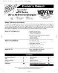
Reliable Emergency Backup Power
Congratulations! You’ve purchased the most advanced, feature-rich Inverter/Charger designed as an alternative energy source during utility
power failures. Tripp Lite APS Inverter/Chargers keep your equipment constantly up and productive through all utility power problems (blackouts,
brownouts and high voltages) by inverting DC power from user-supplied batteries into AC power. Built-in surge suppression provides an additional
level of equipment protection. When utility power is present, APS Inverter/Chargers automatically pass through power to your equipment while
simultaneously recharging your connected battery bank. APS Inverter/Chargers are the quiet alternative to gas generators during emergency
backup applications—with no fumes, fuel or noise to deal with! You get AC electricity anywhere and anytime you need it.
Better for Your Equipment
Premium Protection Levels
• Built-In Surge Protection
• Automatic Overload Protection
Ideal Output for All Loads (including computers)
• Frequency-Controlled Output
• Fast Load Switching
Better for Your Batteries
Faster Battery Recharge
• High-Amp, 3-Stage Battery Charger (adjustable)
Critical Battery Protection
• High-Efficiency DC-to-AC Inversion
Better for You
Simple, Maintenance-Free Operation
• Multi-Function Lights & Switches
• Moisture-Resistant Construction*
Contents
Specifications/Warranty
2
Battery Selection
7
Safety Instructions
3
Mounting
8
Feature Identification
4
Battery Connection
9
Operation
5
AC Input/Output Connection
10
Configuration
6
Service/Maintenance
10
Troubleshooting
11
* Inverter/Chargers are moisture-resistant, not waterproof.
Copyright © 2003. PowerVerter® is a registered trademark of Tripp Lite. All rights reserved.
Specifications
MODEL NUMBER:
AC Input Connection:
APSINT612
Detachable Input Cord
INVERTER
Output Volts (Nominal):
Output Frequency (Nominal):
Efficiency:
Continuous Power (@ 20 C):
OverPower™ Peak Surge Power:*
Double Boost™ Peak Surge Power:*
DC Input Volts (Nominal):
DC Input Voltage Range:
Minimum DC Fuse Rating:
DC Input Current @ Nominal V DC Full Load:
230 VAC, ± 5%
50 Hz, ± 0.5%
88% to 94%, depending on load and temperature
600
900
1200
12 VDC
10-15 VDC
100 A
56 A
BATTERY CHARGER
Input Volts (Nominal):
Charging Capacity DC:
Acceptance Volts VDC Selectable (Wet**/Gel):
Float Volts VDC (w/gel):
Input Current AC (Maximum):
230 VAC
20 A
14.4 V (14.2 V)
13.3 V (13.6 V)
2.2 A
LINE VAC OPERATION
Minimum Input Volts (Transfer to Battery):
Maximum Input Volts (Transfer to Battery):
Selectable 144,** 163, 182 or 201 VAC
Selectable 259** or 278 VAC
Input Frequency (Nominal):
Total Input AC Current (Continuous, Charger at Maximum):
Maximum Output Current (Continuous):
50 Hz, ±10%
4.8 A
2.6 A
* OverPower duration (up to 1 hour). DoubleBoost duration (up to 10 seconds). Actual duration depends on battery age, battery charge level and ambient temperature. ** Factory setting.
The policy of Tripp Lite is one of continuous improvement. Specifications are subject to change without notice.
Minimum Recommended Cable Sizing Charts†
Use in conjunction with DC wiring connection instructions in the Battery Connection section.
Inverter/Charger DC Volt: 12
Wire Gauge
Watts
500
700
6
4
2
0
00 (2/0)
4.8 m (15 ft)
3.4 m (11 ft)
7.6 m (25 ft)
5.5 m (18 ft)
11.9 m (39 ft)
8.5 m (28 ft)
18.9 m (62 ft)
13.4 m (44 ft)
24.1 m (79 ft)
17.1 m (56 ft)
† NOTE: Acceptable power is directly related to cable length (i.e. - the shorter the cable, the better the performance)
Note on Labeling
Two symbols are used on the APS labels.
V~: AC Voltage
: DC Voltage
Limited Warranty
Tripp Lite warrants its Inverter/Chargers to be free from defects in materials and workmanship for a period of one year (except for outside of U.S.A., Canada and Mexico—120 days) from the date of retail purchase by end user
Tripp Lite’s obligation under this warranty is limited to repairing or replacing (at its sole option) any such defective products. To obtain service under this warranty you must obtain a Returned Material Authorization (RMA) number from Tripp Lite or an authorized
Tripp Lite service center. Products must be returned to Tripp Lite or an authorized Tripp Lite service center with transportation charges prepaid and must be accompanied by a brief description of the problem encountered and proof of date and place of purchase. This warranty does not apply to equipment which has been damaged by accident, negligence or misapplication or has been altered or modified in any way, including opening of the unit’s casing for any reason. This warranty applies only to the original purchaser who must have properly registered the product within 10 days of retail purchase.
EXCEPT AS PROVIDED HEREIN, TRIPP LITE MAKES NO WARRANTIES, EXPRESS OR IMPLIED, INCLUDING WARRANTIES OF MERCHANTABILITY AND FITNESS FOR A PARTICULAR PURPOSE. Some states do not permit limitation or exclusion of implied warranties; therefore, the aforesaid limitation(s) or exclusion(s) may not apply to the purchaser.
EXCEPT AS PROVIDED ABOVE, IN NO EVENT WILL TRIPP LITE BE LIABLE FOR DIRECT, INDIRECT, SPECIAL, INCIDENTAL OR CONSEQUENTIAL DAMAGES ARISING OUT OF THE USE OF THIS PRODUCT, EVEN IF ADVISED OF THE POSSIBILITY OF SUCH DAMAGE. Specifically, Tripp Lite is not liable for any costs, such as lost profits or revenue, loss of equipment, loss of use of equipment, loss of software, loss of data, costs of substitutes, claims by third parties, or otherwise.
Tripp Lite has a policy of continuous improvement. Specifications are subject to change without notice.
2A
Important Safety Instructions
SAVE THESE INSTRUCTIONS!
This manual contains important instructions and warnings that should be followed during the installation, operation and storage of all Tripp Lite
Inverter/Chargers.
Location Warnings
• Install your Inverter/Charger (whether for a mobile or stationary application) in a location or compartment that minimizes exposure to
heat, dust, direct sunlight and moisture.
• Although your Inverter/Charger is moisture resistant, it is NOT waterproof. Flooding the unit with water will cause it to short circuit
and could cause personal injury due to electric shock. Never immerse the unit, and avoid any area where standing water might
accumulate. Mounting should be in the driest location available.
• Leave a minimum of 5 cm (2") clearance at front and back of the Inverter/Charger for proper ventilation. The heavier the load of
connected equipment, the more heat will be generated by the unit.
• Do not install the Inverter/Charger directly near magnetic storage media, as this may result in data corruption.
• Do not install near flammable materials, fuel or chemicals.
Battery Connection Warnings
• The Inverter/Charger will not operate (with or without utility power) until batteries are connected.
• Multiple battery systems must be comprised of batteries of identical voltage, age, amp-hour capacity and type.
• Because explosive hydrogen gas can accumulate near batteries if they are not kept well ventilated, your batteries should not be
installed (whether for a mobile or stationary application) in a “dead air” compartment. Ideally, any compartment would have some
ventilation to outside air.
• Sparks may result during final battery connection. Always observe proper polarity as batteries are connected.
• Do not allow objects to contact the two DC input terminals. Do not short or bridge these terminals together. Serious personal injury
or property damage could result.
Equipment Connection Warnings
Do not use a Tripp Lite APS Inverter/Charger in life support or healthcare applications where a malfunction or failure of a
Tripp Lite APS Inverter/Charger could cause failure of or significantly alter the performance of, a life support device or medical
equipment.
• Do not modify the Inverter/Charger’s plug or receptacle in a way that eliminates its ground connection. Do not use
power adapters that will eliminate the plug’s ground connection.
• Connect your Inverter/Charger only to a properly grounded AC power outlet. Do not plug the unit into itself; this will damage the
device and void your warranty.
• You may experience uneven performance results if you connect a surge suppressor, line conditioner or UPS system to the output of the
Inverter/Charger.
Operation Warnings
• Your Inverter/Charger does not require routine maintenance. Do not open the device for any reason. There are no user serviceable parts
inside.
• Potentially lethal voltages exist within the Inverter/Charger as long as the battery supply and/or AC input are connected. During any
service work, the battery supply and AC input connection should therefore be disconnected.
• Do not connect or disconnect batteries while the Inverter/Charger is operating in either inverting or charging mode. Operating Mode
Switch should be in the OFF position. Dangerous arcing may result.
3A
Feature Identification
Identify the premium features on your specific model and quickly locate instructions on how to maximize their use.
1
Configuration DIP Switches: optimize Inverter/Charger
operation depending on your application. See page 6 for
setting instructions.
2
Operating Mode Switch: controls Inverter/Charger operation.
The “AUTO/REMOTE” setting ensures your equipment receives
constant, uninterrupted AC power. It also enables the
Inverter/Charger to be remotely monitored and controlled with
an optional remote module (Tripp Lite model APSRM2, sold
separately). The “CHARGE ONLY” setting allows your batteries
to return to full charge faster by turning the inverter off which
halts battery discharging. See page 5 for setting instructions.
3
4
5
Operation Indicator Lights: intuitive “traffic light” signals
show whether the Inverter/Charger is operating from AC line
power or DC battery power. It also warns you if the connected
equipment load is too high. See page 5 for instructions on reading
indicator lights.
Battery Indicator Lights: intuitive “traffic light” signals show
approximate charge level of your battery. See page 5 for
instructions on reading indicator lights.
6
AC Output Receptacles: allow you to connect equipment that
would normally be plugged into a utility outlet. A universal adapter,
included, allows you to connect a wide variety of plug styles to the
NEMA receptacle. See page 10 for connection instructions.
7
AC Input Receptacle: connects the Inverter/Charger to any
source of utility- or generator-supplied AC power. See page 10
for connection instructions.
8
Resettable Circuit Breakers: protect your Inverter/Charger
against damage due to overload. See page 5 for resetting instructions.
9
Remote Control Module Connector: allows remote monitoring
and control with an optional module (Tripp Lite model
APSRM2, sold separately). See remote module owner’s manual
for connection instructions.
10
Main Ground Lug: properly grounds the Inverter/Charger to
earth ground or to vehicle or boat grounding system. See page
9 for connection instructions.
11
Multi-Speed Cooling Fan: quiet, efficient fan prolongs equipment
service life.
DC Power Terminals: connect to your battery terminals. See
page 9 for connection instructions.
11
1
4
9
3
2
8
10
6
Front View (APSINT612)
5
7
4A
Operation
Switch Modes
After configuring, mounting and connecting your Inverter/Charger, you
are able to operate it by switching between the following operating
modes as appropriate to your situation:
AUTO/REMOTE: Switch to this mode when you
need constant, uninterrupted AC power for connected
appliances and equipment. The Inverter/Charger will
continue to supply AC power to connected equipment
and to charge your connected batteries while utilityor generator-supplied AC power is present. Since the
inverter is ON (but in Standby) in this mode, it will automatically
switch to your battery system to supply AC power to connected
equipment in the absence of a utility/generator source or in over/under
voltage situations. “AUTO/REMOTE” also enables an optional remote
control module (Tripp Lite model APSRM2, sold separately) to
function when connected to the unit.
CHARGE ONLY: Switch to this mode when you
are not using connected appliances and equipment in
order to conserve battery power by disabling the
inverter. The Inverter/Charger will continue to supply
AC power to connected equipment and charge connected batteries while utility- or generator-supplied
AC power is present. However, since the inverter is OFF in this
mode, it WILL NOT supply AC power to connected equipment in the
absence of a utility/generator source or in over/under voltage situations.
OFF: Switch to this mode to shut down the
Inverter/Charger completely, preventing the inverter
from drawing power from the batteries, and preventing
utility AC from passing through to connected equipment
or charging the batteries. Use this switch to automatically
reset the unit if it shuts down due to overload or overheating. First remove the excessive load or allow the unit to sufficiently cool (applicable to your situation). Switch to “OFF”, then
back to “AUTO/REMOTE” or “CHARGE ONLY” as desired. If unit
fails to reset, remove more load or allow unit to cool further and
retry. Use an optional remote control module (Tripp Lite model
APSRM2, sold separately) to reset unit due to overload only.
LOAD Red Indicator: This red light will ILLUMINATE CONTINUOUSLY whenever the inverter is
functioning and the power demanded by connected
appliances and equipment exceeds 100% of load
capacity. The light will FLASH to alert you when the
inverter shuts down due to a severe overload or overheating. If this happens, turn the operating mode switch “OFF”;
remove the overload and let the unit cool. You may then turn the
operating mode switch to either “AUTO/REMOTE” or “CHARGE
ONLY” after it has adequately cooled. This light will be off when
AC power is supplying the load.
BATTERY Indicator Lights: These three lights will illuminate in
several sequences to show the approximate charge level of your connected battery bank and alert you to two fault conditions:
Approximate Battery Charge Level*
Indicator Illuminated Battery Capacity
(Charging/Discharging)
1
2
3
4
5
6
7
Green
Green & Yellow
Yellow
Yellow & Red
Red
All three lights off
Flashing red
91%–Full
81%–90%
61%–80%
41%–60%
21%–40%
1%–20%
0% (Inverter
shutdown)
* Charge levels listed are approximate. Actual conditions vary
depending on battery condition and load.
Fault Condition
Indicator Illuminated
1 All three lights
flash slowly*
2 All three lights
flash quickly**
1
2
3
4
5
6
7
Fault Condition
Excessive discharge
(Inverter shutdown)
Overcharge (Charger
shutdown)
1
2
*Approximately ½ second on, ½ second off. See Troubleshooting section. ** Approximately ¼ second
on, ¼ second off. May also indicate a battery charger fault exists. See Troubleshooting section.
Indicator Lights
Your Inverter/Charger (as well as an optional Tripp Lite Remote
Control Module, sold separately) is equipped with a simple, intuitive,
user-friendly set of indicator lights. These easily-remembered “traffic
light” signals will allow you, shortly after first use, to tell at a glance
the charge condition of your batteries, as well as ascertain operating
details and fault conditions.
LINE Green Indicator: If the operating mode
switch is set to “AUTO/REMOTE,” this light will
ILLUMINATE CONTINUOUSLY when your connected equipment is receiving continuous AC power
supplied from a utility/generator source.
If the operating mode switch is set to “CHARGE ONLY,” this light
will FLASH to alert you that the unit’s inverter is OFF and will NOT
supply AC power in the absence of a utility/generator source or in
over/under voltage situations.
INV (Inverting) Yellow Indicator: This light will
ILLUMINATE CONTINUOUSLY whenever connected
equipment is receiving battery-supplied, inverted AC
power (in the absence of a utility/generator source or
in over/under voltage situations). This light will be
off when AC power is supplying the load.
Resetting Your Inverter/Charger
to Restore AC Power
Your Inverter/Charger may cease supplying AC power or DC charging
power in order to protect itself from overload or to protect your electrical system. To restore normal functioning:
Overload Reset: Switch operating mode switch to “OFF” and
remove some of the connected electrical load (ie: turn off some of
the AC devices drawing power which may have caused the overload
of the unit). Wait one minute, then switch operating mode switch
back to either “AUTO/REMOTE” or “CHARGE ONLY.”
Output Circuit Breaker Reset: Alternatively, check output circuit
breaker(s) on the unit’s front panel. If tripped, remove some of the electrical load, then wait one minute to allow components to cool before
resetting the circuit breaker. See Troubleshooting for other possible
reasons AC output may be absent.
5A
Configuration
Set Configuration DIP Switches
Using a small tool, set the Configuration DIP Switches (located on the front panel of your unit, see diagram) to optimize Inverter/Charger
operation depending on your application.
A4
INPUT C/B 10A
A3
A2
A1
OUTPUT C/B 12A
Dip Switches
DIP Switches
A1
Select Battery Type—REQUIRED
A2
A4 A3 A2 A1
CAUTION: The Battery Type DIP Switch setting must match
the type of batteries you connect, or your batteries may be
degraded or damaged over an extended period of time. See
“Battery Selection,” p. 7 for more information.
Battery Type
Gel Cell (Sealed) Battery
Wet Cell (Vented) Battery
A4 A3
Switch Position
Up
Down (factory setting)
Select High AC Input Voltage Point
for Switching to Battery—OPTIONAL*
Voltage
278V
259V
Switch Position
Up
Down (factory setting)
Select Low AC Input Voltage Point for Switching to
Battery—OPTIONAL*
Voltage
201V
182V
163V
144V
Switch Position
#A4 Up & #A3 Up
#A4 Up & #A3 Down
#A4 Down & #A3 Up
#A4 Down & #A3 Down (factory setting)
* Most of your connected appliances and equipment will perform adequately when your Inverter/Charger’s High AC Input Voltage Point is left in the factory setting and its Low AC Voltage Input
Point is set to 182V. However, if the unit frequently switches to battery power due to momentary high/low line voltage swings that would have little effect on equipment operation, you may wish to
adjust these settings. By increasing the High AC Voltage Point and/or decreasing the Low AC Voltage Point, you will reduce the number of times your unit switches to battery due to voltage swings.
Connect Remote Control—Optional
All models feature an 8-conductor telephone style receptacle on the front panel for use with an optional remote control module (Tripp Lite
model APSRM2, sold separately). The remote module allows the Inverter/Charger to be mounted in a compartment or cabinet out of sight, while
operated conveniently from a remote location. See instructions packed with the remote control module.
6A
Battery Selection
Select Battery Type
Select “Deep Cycle” batteries to enjoy optimum performance from your Inverter/Charger. Batteries of either Wet-Cell (vented) or Gel-Cell /Absorbed
Glass Mat (sealed) construction are ideal. 6-volt “golf cart,” Marine Deep-Cycle or 8D Deep-Cycle batteries are also acceptable. You must
set the Inverter/Charger’s Battery Type DIP Switch (see Configuration section for more information) to match the type of batteries you connect
or your batteries may be degraded or damaged over an extended period of time.
Match Battery Amp-Hour Capacity to Your Application
Select a battery or system of batteries that will provide your Inverter/Charger with proper DC voltage and an adequate amp-hour capacity
to power your application. Even though Tripp Lite Inverter/Chargers are highly-efficient at DC-to-AC inversion, their rated output capacities
are limited by the total amp-hour capacity of connected batteries plus the output of an alternator when one is used.
Example
• STEP 1) Determine Total Wattage Required
Add the wattage ratings of all equipment you will connect to your
Inverter/Charger. Wattage ratings are usually listed in equipment manuals
or on nameplates. If your equipment is rated in amps, multiply that number
times AC utility voltage to estimate watts. (Example: a ¼ in. drill requires
1.3 amps. 1.3 amps × 230 volts = 300 watts.)
NOTE: Your Inverter/Charger will operate at higher efficiencies at about 75% - 80% of nameplate rating.
Tools
¼" Drill
300W
Orbital Sander
+
220W
Cordless Tool Charger
+
20W
=
540W
=
540W
Appliances
Blender
300W
• STEP 2) Determine DC Battery Amps Required
Divide the total wattage required (from step 1, above) by the battery voltage
(12) to determine the DC amps required.
• STEP 3) Estimate Battery Amp-Hours Required
Multiply the DC amps required (from step 2, above) by the number of hours
you estimate you will operate your equipment exclusively from battery
power before you have to recharge your batteries with utility- or generator-supplied AC power. Compensate for inefficiency by multiplying this
number by 1.2. This will give you a rough estimate of how many amp-hours
of battery power (from one or several batteries) you should connect to
your Inverter/Charger.
Color TV
+
140W
Laptop Computer
+
100W
540 watts ÷ 12V = 45 DC Amps
45 DC Amps × 5 Hrs. Runtime
× 1.2 Inefficiency Rating = 270 Amp-Hours
NOTE: Battery amp-hour ratings are usually given for a 20-hour discharge rate. Actual amp-hour capacities
are less when batteries are discharged at faster rates. For example, batteries discharged in 55 minutes
provide only 50% of their listed amp-hour ratings, while batteries discharged in 9 minutes provide as little
as 30% of their amp-hour ratings.
• STEP 4) Estimate Battery Recharge Required, Given Your Application
You must allow your batteries to recharge long enough to replace the
charge lost during inverter operation or else you will eventually run down
your batteries. To estimate the minimum amount of time you need to
recharge your batteries given your application, divide your required battery
amp-hours (from step 3, above) by your Inverter/Charger’s rated charging
amps (see Specifications section).
NOTE: For Tripp Lite Inverter/Chargers providing 1000 watts or less of continuous AC power, a full-size
battery will normally allow sufficient power for many applications before recharging is necessary. For
mobile applications, if a single battery is continuously fed by an alternator at high idle or faster, then recharging
from utility or generator power may not be necessary. Tripp Lite Inverter/Chargers will provide adequate
power for ordinary usage within limited times without the assistance of utility or generator power.
However, when operating extremely heavy electrical loads at their peak in the absence of utility power,
you may wish to “assist your batteries” by running an auxiliary generator or vehicle engine, and doing
so at faster than normal idling.
7A
270 Amp-Hours ÷ 20 Amps
Inverter/Charger Rating = 13.5 Hours Recharge
Mounting
WARNING! Mount your Inverter/Charger BEFORE DC battery and AC power
connection. Failure to follow these instructions may lead to personal injury
and/or damage to the Inverter/Charger and connected systems.
Tripp Lite manufactures a variety of different Inverter/Chargers with a variety of different mounting options for use in vehicular or non-vehicular
applications. Tripp Lite recommends permanent mounting of your Inverter/Charger in any of the configurations illustrated below. User must
supply mounting hardware and is responsible for determining if the hardware and mounting surface are suitable to support the weight of the
Inverter/Charger. Contact Tripp Lite if you require further assistance in mounting your Inverter/Charger.
Vehicular and Non-Vehicular Horizontal Mount
A Install two user-supplied 6 mm (¼") fasteners into a rigid horizontal surface, leaving the heads slightly raised. B Slide the
Inverter/Charger back over the fasteners to engage the mounting slots molded on the bottom of the Inverter/Charger cabinet. C Install and
tighten two user-supplied 6 mm (¼") fasteners into the mounting feet molded on the front of the Inverter/Charger cabinet.
M
C
A
B
8A
Battery Connection
Connect your Inverter/Charger to your batteries using the following procedures:
• Connect DC Wiring: Though your
• Connect Ground: Using a #8 AWG wire or larger directly connect
Inverter/Charger is a high-efficiency conthe Main Ground Lug to the vehicle’s chassis or earth ground. See
verter of electricity, its rated output capacity
the Feature Identification section to locate the Main Ground Lug on
is limited by the length and gauge of the
your specific Inverter/Charger model. All installations must comply
cabling running from the battery to the unit.
with national and local codes and ordinances.
Use the shortest length and largest diameter DC Connectors
• Connect Fuse: NEC (National Electrical Code) article 551
cabling (maximum 2/0 gauge) to fit your Inverter/Charger’s DC Input
requires that you connect all of your Inverter/Charger’s positive DC
terminals. Shorter and heavier gauge cabling reduces DC voltage drop
Terminals directly to a UL-listed fuse(s) and fuse block(s) within 45
and allows for maximum transfer of current. Your Inverter/Charger
cm (18 inches) of the battery. The fuse’s rating must equal or exceed
is capable of delivering peak wattage at up to 200% of its rated conthe Minimum DC Fuse Rating listed in your Inverter/Charger’s
tinuous wattage output for brief periods of time. See Specifications
specifications. See Specifications for fuse and fuse block recompage for details. Heavier gauge cabling should be used when continmendations. See diagrams below for proper fuse placement.
uously operating heavy draw equipment under these conditions.
Tighten your Inverter/Charger and battery terminals to approximately 3.5 Newton-meters of torque to create an efficient connection and
to prevent excessive heating at this connection. Insufficient tightening of the terminals could void your warranty. See Specifications
page for Minimum Recommended Cable Sizing Chart.
WARNING!
• Failure to properly ground your Inverter/Charger to a vehicle’s chassis or earth ground may result
in a lethal electrical shock hazard.
• Never attempt to operate your Inverter/Charger by connecting it directly to output from an
alternator rather than a battery or battery bank.
• Observe proper polarity with all DC connections.
Non-Vehicular or Vehicular
Non-vehicular applications include stationary configurations as well as mobile configurations that are not integrated into a vehicle’s electrical
system. In a parallel connection, your Inverter/Charger’s Nominal DC Input Voltage (listed in the Specifications section must match the
voltage of your battery or batteries. For example, a 12V DC Inverter/Charger would require 12V DC from your battery system.
In a series connection, your Inverter/Charger’s Nominal DC Input Voltage must match the number of batteries multiplied by their voltage. For
example, a 12V DC Inverter/Charger would require two 6V batteries connected in series (12 = 2 × 6).
In vehicular applications, your Inverter/Charger’s Nominal DC Input Voltage must match the voltage of your battery or batteries—
12 Volts. Although it is possible to connect your Inverter/Charger to the main battery within your vehicle’s electrical system, in the normal
vehicular context, the Inverter/Charger is connected to one or more dedicated auxiliary (house) batteries which are isolated from the drive
system to prevent possible draining of the main battery.
Contact Tripp Lite technical support for assistance with additional parallel, series or series/parallel connections.
4
Optional connection
for Vehicular
applications only.
1
5
12 Volts
2
12 Volt Inverter/Charger
3
Single Battery Connection
4
1
6 Volts
6 Volts
2
12 Volt Inverter/Charger
2
Multiple Battery Connection (Series)
3
1 Earth or Vehicle/Boat Battery Ground 2 Battery 3 UL-Listed Fuse & Fuse Block [mounted within 45 cm (18 inches) of the battery] 4 Large Diameter
Cabling, Maximum 2/0 Gauge to Fit Terminals 5 Alternator (for vehicle or boat connection only)
9A
AC Input/Output Connection
To avoid overloading your Inverter/Charger, be sure to match the power requirements of the equipment you plan to run at any one time (add their
total watts) with the output wattage capacity of your Inverter/Charger model (see Specifications). When figuring the power requirements of
your equipment, do not confuse “continuous” wattage with “peak” wattage ratings. Most electric motors require extra power at start-up
(“peak” wattage) than required to run continuously after start-up, sometimes over 100% more. Some motors, such as in refrigerators and
pumps, start and stop intermittently according to demand, requiring “peak” wattage at multiple, unpredictable times during operation.
• DoubleBoost™ Feature
Tripp Lite Inverter/Chargers deliver up to twice their nameplate
rated wattage for up to 10 seconds,* providing the extra power
needed to cold start heavy-duty tools and equipment.
• OverPower™ Feature
Tripp Lite Inverter/Chargers deliver up to 150% of their name
plate rated wattage for up to 1 hour,* providing plenty of reserve
power to reliably support tools and equipment longer.
* Actual duration depends on battery age, battery charge level and ambient temperature.
AC Input Connection
Connect one end of the detachable 2 meter power cord, included, into the IEC-320 AC Input receptacle. Connect the other end to your wall
outlet. If the plug on the cord does not match your wall receptacle, you can remove a detachable cord from another piece of equipment (such
as a computer or monitor) that does have the appropriate plug and use that as the Inverter/Charger power cord. Then use the included detachable
2 meter cord to connect the piece of equipment, whose cord you've removed, to the NEMA 5-15R output receptacle on the Inverter/Charger.
AC Output Connection
Simply connect equipment directly to the IEC-320 and NEMA output receptacles. A universal adapter, included, allows you to connect a
wide variety of plug styles to the NEMA receptacle.
Service
If you are returning your Inverter/Charger to Tripp Lite, please pack it carefully, using the ORIGINAL PACKING MATERIAL that came
with the unit. Enclose a letter describing the symptoms of the problem. If the Inverter/Charger is within the warranty period, enclose a copy
of your sales receipt. To obtain service you must obtain a Returned Material Authorization (RMA) number from Tripp Lite or an authorized Tripp Lite service center.
Maintenance
Your Inverter/Charger requires no maintenance and contains no user-serviceable or replaceable parts, but should be kept dry at all times.
Periodically check, clean and tighten all cable connections as necessary, both at the unit and at the battery.
10A
Troubleshooting
Try these remedies for common Inverter/Charger problems before calling for assistance. Call Tripp Lite Customer Service at (773) 869-1212
before returning your unit for service.
Battery Indicator Lights
Operating Mode Switch
MAX
(GREATER
LOAD
ON)
Operation Indicator Lights
OFF
(LESSER
LOAD
ON)
SYMPTOM
PROBLEMS
CORRECTIONS
No AC Output
(All Indicator Lights Are OFF)
Unit is not properly connected to utility power.
Connect unit to utility power.
Operating Mode Switch is set to “OFF” and
AC input is present.
Set Operating Mode Switch to “AUTO/REMOTE” or “CHARGE ONLY.”
This is normal when the Operating Mode Switch
is set to “CHARGE ONLY” and AC input is absent.
No correction is required. AC output will return when AC input
returns. Set Operating Mode Switch to “AUTO/REMOTE” if you
require AC output.
Circuit breaker is tripped.
Reset circuit breaker.
Unit has shut down due to battery overcharge (preventing
battery damage). The problem may be with connected
auxiliary chargers, if any, or with the unit’s charger.
Disconnect any auxiliary chargers. Reset by moving Operating
Mode Switch to “OFF.” Wait 1 minute and switch to “AUTO/REMOTE”
or “CHARGE ONLY.” If unit remains in shutdown mode after several
attempts to reset, contact Tripp Lite Customer Service for assistance.
Unit has shut down due to excessive battery discharge.
Use an auxiliary charger* to raise battery voltage. Check external
battery connections and fuse. Unit automatically resets when
condition is cleared.
Unit has shut down due to overload.
Reduce load. Reset by moving Operating Mode Switch to “OFF.”
Wait 1 minute. Switch to “AUTO/REMOTE” or “CHARGE ONLY.”
Connected batteries are dead.
Check and replace old batteries.
Battery fuse* is blown.
Check and replace fuse.*
Battery cabling* is loose.
Check and tighten or replace cabling.*
Unit has shut down due to battery overcharge (preventing
battery damage). The problem may be with connected
auxiliary chargers, if any, or with the unit’s charger.
Disconnect any auxiliary chargers. Reset by moving Operating Mode
Switch to “OFF.” Wait 1 minute and switch to “AUTO/REMOTE” or
“CHARGE ONLY.” If unit remains in shutdown mode after several
attempts to reset, contact Tripp Lite Customer Service for assistance.
Input circuit breaker is tripped.
Reset circuit breaker.
All Three Battery Indicator Lights
Are Slowly Flashing
(½ Second Flashes)
Battery is excessively discharged.
Use an auxiliary charger* to raise battery voltage. Check external
battery connections and fuse. Unit automatically resets when
condition is cleared.
All Three Battery Indicator Lights
Are Rapidly Flashing
(¼ Second Flashes)
Battery is overcharged. Unit will shut down to prevent
battery damage. The problem may be with connected
auxiliary chargers, if any, or with the unit’s charger.
Disconnect any auxiliary chargers. Reset by moving Operating Mode
Switch to “OFF.” Wait 1 minute and switch to “AUTO/REMOTE”
or “CHARGE ONLY.” If unit remains in shutdown mode after several
attempts to reset, contact Tripp Lite Customer Service for assistance.
Red “LOW” Battery
Indicator Light is Flashing
Battery voltage is low. Unit will automatically shut down
after 5 seconds to protect battery from damage.
Make sure that AC power is present in order to recharge batteries.
Reset by moving Operating Mode Switch to “OFF then to
“AUTO/REMOTE” or “CHARGE ONLY.”
False reading due to undersized or insufficiently connected
DC cabling.
Use sufficient size DC cable sufficiently connected to the
Inverter/Charger.
Inverter is overloaded. Unit will automatically shut down
after 5 seconds.
Reduce load. Reset by moving Operating Mode Switch to “OFF.”
Wait 1minute. Switch to “AUTO/REMOTE” or “CHARGE ONLY.”
Battery Not Recharging
(AC Input Present)
Red “LOAD” Operation
Indicator Light Flashing
* User-supplied.
11A
1111 W. 35th Street, Chicago, IL 60609 USA
Customer Support: (773) 869-1212
www.tripplite.com
200302117 93-2113