1
200711151 93-2751 120V APS OM.qxd
11/29/2007
2:47 PM
Page 5
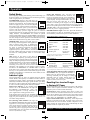
Operation
Switch Modes
After configuring, mounting and connecting your Inverter/Charger, you
are able to operate it by switching between the following operating
modes as appropriate to your situation:
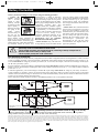
AUTO/REMOTE: Switch to this mode when you
need constant, uninterrupted AC power for connected
appliances and equipment. The Inverter/Charger will
continue to supply AC power to connected equipment
and to charge your connected batteries while utilityor generator-supplied AC power is present. Since the
inverter is ON (but in Standby) in this mode, it will automatically
switch to your battery system to supply AC power to connected
equipment in the absence of a utility/generator source or in over/under
voltage situations. “AUTO/REMOTE” also enables an optional
remote control module (Tripp Lite model APSRM2, sold separately
or included with select models) to function when connected to the
unit. This setting also allows operation of the Redundant Operating
Mode Switch mounted on the top panel of select models
CHARGE ONLY: Switch to this mode when you
are not using connected appliances and equipment in
order to conserve battery power by disabling the
inverter. The Inverter/Charger will continue to supply
AC power to connected equipment and charge
connected batteries while utility- or generatorsupplied AC power is present. However, since the inverter is OFF in
this mode, it WILL NOT supply AC power to connected equipment in
the absence of a utility/generator source or in over/under voltage
situations.
OFF: Switch to this mode to shut down the
Inverter/Charger completely, preventing the inverter
from drawing power from the batteries, and preventing
utility AC from passing through to connected equipment
or charging the batteries. Use this switch to automatically
reset the unit if it shuts down due to overload or
overheating. First remove the excessive load or allow the unit to
sufficiently cool (applicable to your situation). Switch to “OFF”,
then back to “AUTO/REMOTE” or “CHARGE ONLY” as desired.
If unit fails to reset, remove more load or allow unit to cool further
and retry. Use an optional remote control module (Tripp Lite model
APSRM2, sold separately or included with select models) to reset
unit due to overload only.
Indicator Lights
Your Inverter/Charger (as well as an optional Tripp Lite Remote
Control Module, sold separately or included with select models) is
equipped with a simple, intuitive, user-friendly set of indicator lights.
These easily-remembered “traffic light” signals will allow you, shortly
after first use, to tell at a glance the charge condition of your batteries,
as well as ascertain operating details and fault conditions.
LINE Green Indicator: If the operating mode
switch is set to “AUTO/REMOTE,” this light will
ILLUMINATE CONTINUOUSLY when your
connected equipment is receiving continuous AC
power supplied from a utility/generator source.
If the operating mode switch is set to “CHARGE ONLY,” this light
will FLASH to alert you that the unit’s inverter is OFF and will NOT
supply AC power in the absence of a utility/generator source or in
over/under voltage situations.
INV (Inverting) Yellow Indicator: This light will
ILLUMINATE CONTINUOUSLY whenever connected
equipment is receiving battery-supplied, inverted AC
power (in the absence of a utility/generator source or
in over/under voltage situations). This light will be
off when AC power is supplying the load. This light
will FLASH to alert you if the load is less than the Battery Charge
Conserver (Load Sense) setting.
5A
LOAD Red Indicator: This red light will
ILLUMINATE CONTINUOUSLY whenever the
inverter is functioning and the power demanded by
connected appliances and equipment exceeds 100%
of load capacity. The light will FLASH to alert you
when the inverter shuts down due to a severe
overload or overheating. If this happens, turn the operating mode
switch “OFF”; remove the overload and let the unit cool. You may
then turn the operating mode switch to either “AUTO/REMOTE” or
“CHARGE ONLY” after it has adequately cooled. This light will be
off when AC power is supplying the load.
BATTERY Indicator Lights: These three lights will illuminate in
several sequences to show the approximate charge level of your
connected battery bank and alert you to two fault conditions:
Approximate Battery Charge Level*
Indicator Illuminated Battery Capacity
(Charging/Discharging)
1
2
3
4
5
6
7
Green
Green & Yellow
Yellow
Yellow & Red
Red
All three lights off
Flashing red
91%–Full
81%–90%
61%–80%
41%–60%
21%–40%
1%–20%
0% (Inverter
shutdown)
* Charge levels listed are approximate. Actual conditions vary
depending on battery condition and load.
Fault Condition
Indicator Illuminated
1 All three lights
flash slowly*
2 All three lights
flash quickly**
1
2
3
4
5
6
7
Fault Condition
Excessive discharge
(Inverter shutdown)
Overcharge (Charger
shutdown)
1
2
*Approximately ½ second on, ½ second off. See Troubleshooting section. ** Approximately ¼ second
on, ¼ second off. May also indicate a battery charger fault exists. See Troubleshooting section.
Voltage Regulation Indicator Lights (available on
select models): these green lights will illuminate to
indicate when the Inverter/Charger is automatically
“boosting” abnormally low AC voltage or “cutting”
abnormally high AC voltage without relying on
battery power. This function is automatic and
requires no action on the user’s part.
Resetting Your Inverter/Charger
to Restore AC Power
Your Inverter/Charger may cease supplying AC power or DC charging
power in order to protect itself from overload or to protect your
electrical system. To restore normal functioning:
Overload Reset: Switch operating mode switch to “OFF” and
remove some of the connected electrical load (ie: turn off some of
the AC devices drawing power which may have caused the overload
of the unit). Wait one minute, then switch operating mode switch
back to either “AUTO/REMOTE” or “CHARGE ONLY.”
Output Circuit Breaker Reset: Alternatively, check output circuit
breaker(s) on the unit’s front panel. If tripped, remove some of the
electrical load, then wait one minute to allow components to cool
before resetting the circuit breaker. See Troubleshooting for other
possible reasons AC output may be absent.
See page 11 for Redundant Switch/Indicator Light Panel