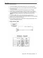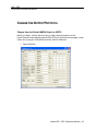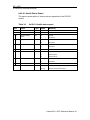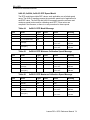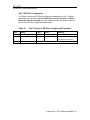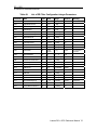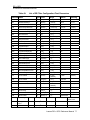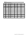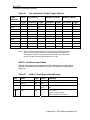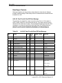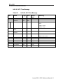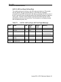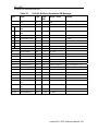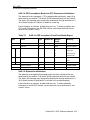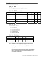
1
REFERENCE MANUAL USER GUIDE Lassen DR+GPS NORTH AMERICA Trimble Navigation Limited Corporate Headquarters 935 Stewart Drive Sunnyvale, CA 94086 +1-800-787-4225 +1-408-481-7741 [email protected] EUROPE Trimble Navigation Europe Phone: +49-6142-2100-161 KOREA Trimble Export Ltd, Korea Phone: +82 2 555 5361 CHINA Trimble Navigation Ltd, China Phone: +86-21-6391-7814 www.trimble.com USER GUIDE REFERENCE MANUAL LASSEN® DR+GPS STARTER KIT Revision A Part Number 58059-00 March 2007 Corporate Office Trimble Navigation Limited Advanced Devices Group 935 Stewart Avenue Sunnyvale, CA 94086 USA +1-800-787-4225 (toll free in USA) +1-408-481-7741 www.trimble.com Release Notice This is the March 2007 release (Revision A) of the Trimble Lassen DR+GPS Starter Kit User Guide, part number 58059-00. Copyright and Trademarks © 2007, Trimble Navigation Limited. Trimble and the Globe & Triangle logo are trademarks of Trimble Navigation Limited, registered in the United States Patent and Trademark Office and in other countries. Bullet, and Mini-T are trademarks of Trimble Navigation Limited. Microsoft and Windows are either registered trademarks or trademarks of Microsoft Corporation in the United States and/or other countries. All other trademarks are the property of their respective owners. Product Limited Warranty Information For applicable product Limited Warranty information, please consult your local Trimble authorized sales manager. For applicable product Limited Warranty information, please refer to Legal Notices in the Help for this product, or consult your local Trimble authorized dealer. RoHS statement As of July 1, 2006, the Product is compliant in all material respects with DIRECTIVE 2002/95/EC OF THE EUROPEAN PARLIAMENT AND OF THE COUNCIL of 27 January 2003 on the restriction of the use of certain hazardous substances in electrical and electronic equipment (RoHS Directive) and Amendment 2005/618/EC filed under C(2005) 3143, with exemptions for lead in solder pursuant to Paragraph 7 of the Annex to the RoHS Directive applied. The foregoing is limited to Product placed on the market in the Member States of the European Union on or after 1 July 2006. Trimble has relied on representations made by its suppliers in certifying this Product as RoHS compliant. LIMITED WARRANTY TERMS AND CONDITIONS Product Limited Warranty Subject to the following terms and conditions, Trimble Navigation Limited (“Trimble”) warrants that for a period of one (1) year from date of purchase this Trimble product (the “Product”) will substantially conform to Trimble's publicly available specifications for the Product and that the hardware and any storage media components of the Product will be substantially free from defects in materials and workmanship. Product Software Product software, whether built into hardware circuitry as firmware, provided as a standalone computer software product, embedded in flash memory, or stored on magnetic or other media, is licensed solely for use with or as an integral part of the Product and is not sold. If accompanied by a separate end user license agreement (“EULA”), use of any such software will be subject to the terms of such end user license agreement (including any differing limited warranty terms, exclusions, and limitations), which shall control over the terms and conditions set forth in this limited warranty. Software Fixes During the limited warranty period you will be entitled to receive such Fixes to the Product software that Trimble releases and makes commercially available and for which it does not charge separately, subject to the procedures for delivery to purchasers of Trimble products generally. If you have purchased the Product from an authorized Trimble dealer rather than from Trimble directly, Trimble may, at its option, forward the software Fix to the Trimble dealer for final distribution to you. Minor Updates, Major Upgrades, new products, or substantially new software releases, as identified by Trimble, are expressly excluded from this update process and limited warranty. Receipt of software Fixes or other enhancements shall not serve to extend the limited warranty period. For purposes of this warranty the following definitions shall apply: (1) “Fix(es)” means an error correction or other update created to fix a previous software version that does not substantially conform to its Trimble specifications; (2) “Minor Update” occurs when enhancements are made to current features in a software program; and (3) “Major Upgrade” occurs when significant new features are added to software, or when a new product containing new features replaces the further development of a current product line. Trimble reserves the right to determine, in its sole discretion, what constitutes a Fix, Minor Update, or Major Upgrade. Warranty Remedies If the Trimble Product fails during the warranty period for reasons covered by this limited warranty and you notify Trimble of such failure during the warranty period, Trimble will repair OR replace the nonconforming Product with new, equivalent to new, or reconditioned parts or Product, OR refund the Product purchase price paid by you, at Trimble’s option, upon your return of the Product in accordance with Trimble's product return procedures then in effect. How to Obtain Warranty Service To obtain warranty service for the Product, please contact your local Trimble authorized dealer. Alternatively, you may contact Trimble to request warranty service at +1-408-4816940 (24 hours a day) or e-mail your request to [email protected]. Please be prepared to provide: ⎯ your name, address, and telephone numbers proof of purchase ⎯ a description of the nonconforming Product including the model number and serial number ⎯ an explanation of the problem The customer service representative may need additional information from you depending on the nature of the problem. Warranty Exclusions and Disclaimer This Product limited warranty shall only apply in the event and to the extent that (a) the Product is properly and correctly installed, configured, interfaced, maintained, stored, and operated in accordance with Trimble's applicable operator's manual and specifications, and; (b) the Product is not modified or misused. This Product limited warranty shall not apply to, and Trimble shall not be responsible for, defects or performance problems resulting from (i) the combination or utilization of the Product with hardware or software products, information, data, systems, interfaces, or devices not made, supplied, or specified by Trimble; (ii) the operation of the Product under any specification other than, or in addition to, Trimble's standard specifications for its products; (iii) the unauthorized installation, modification, or use of the Product; (iv) damage caused by: accident, lightning or other electrical discharge, fresh or salt water immersion or spray (outside of Product specifications); or exposure to environmental conditions for which the Product is not intended; (v) normal wear and tear on consumable parts (e.g., batteries); or (vi) cosmetic damage. Trimble does not warrant or guarantee the results obtained through the use of the Product, or that software components will operate error free. NOTICE REGARDING PRODUCTS EQUIPPED WITH TECHNOLOGY CAPABLE OF TRACKING SATELLITE SIGNALS FROM SATELLITE BASED AUGMENTATION SYSTEMS (SBAS) (WAAS/EGNOS, AND MSAS), OMNISTAR, GPS, MODERNIZED GPS OR GLONASS SATELLITES, OR FROM IALA BEACON SOURCES: TRIMBLE IS NOT RESPONSIBLE FOR THE OPERATION OR FAILURE OF OPERATION OF ANY SATELLITE BASED POSITIONING SYSTEM OR THE AVAILABILITY OF ANY SATELLITE BASED POSITIONING SIGNALS. THE FOREGOING LIMITED WARRANTY TERMS STATE TRIMBLE’S ENTIRE LIABILITY, AND YOUR EXCLUSIVE REMEDIES, RELATING TO THE TRIMBLE PRODUCT. EXCEPT AS OTHERWISE EXPRESSLY PROVIDED HEREIN, THE PRODUCT, AND ACCOMPANYING DOCUMENTATION AND MATERIALS ARE PROVIDED “AS-IS” AND WITHOUT EXPRESS OR IMPLIED WARRANTY OF ANY KIND, BY EITHER TRIMBLE OR ANYONE WHO HAS BEEN INVOLVED IN ITS CREATION, PRODUCTION, INSTALLATION, OR DISTRIBUTION, INCLUDING, BUT NOT LIMITED TO, THE IMPLIED WARRANTIES OF MERCHANTABILITY AND FITNESS FOR A PARTICULAR PURPOSE, TITLE, AND NONINFRINGEMENT. THE STATED EXPRESS WARRANTIES ARE IN LIEU OF ALL OBLIGATIONS OR LIABILITIES ON THE PART OF TRIMBLE ARISING OUT OF, OR IN CONNECTION WITH, ANY PRODUCT. BECAUSE SOME STATES AND JURISDICTIONS DO NOT ALLOW LIMITATIONS ON DURATION OR THE EXCLUSION OF AN IMPLIED WARRANTY, THE ABOVE LIMITATION MAY NOT APPLY OR FULLY APPLY TO YOU. Limitation of Liability TRIMBLE'S ENTIRE LIABILITY UNDER ANY PROVISION HEREIN SHALL BE LIMITED TO THE AMOUNT PAID BY YOU FOR THE PRODUCT. TO THE MAXIMUM EXTENT PERMITTED BY APPLICABLE LAW, IN NO EVENT SHALL TRIMBLE OR ITS SUPPLIERS BE LIABLE FOR ANY INDIRECT, SPECIAL, INCIDENTAL, OR CONSEQUENTIAL DAMAGE WHATSOEVER UNDER ANY CIRCUMSTANCE OR LEGAL THEORY RELATING IN ANYWAY TO THE PRODUCTS, SOFTWARE AND ACCOMPANYING DOCUMENTATION AND MATERIALS, (INCLUDING, WITHOUT LIMITATION, DAMAGES FOR LOSS OF BUSINESS PROFITS, BUSINESS INTERRUPTION, LOSS OF DATA, OR ANY OTHER PECUNIARY LOSS), REGARDLESS OF WHETHER TRIMBLE HAS BEEN ADVISED OF THE POSSIBILITY OF ANY SUCH LOSS AND REGARDLESS OF THE COURSE OF DEALING WHICH DEVELOPS OR HAS DEVELOPED BETWEEN YOU AND TRIMBLE. BECAUSE SOME STATES AND JURISDICTIONS DO NOT ALLOW THE EXCLUSION OR LIMITATION OF LIABILITY FOR CONSEQUENTIAL OR INCIDENTAL DAMAGES, THE ABOVE LIMITATION MAY NOT APPLY TO YOU. PLEASE NOTE: THE ABOVE TRIMBLE LIMITED WARRANTY PROVISIONS WILL NOT APPLY TO PRODUCTS PURCHASED IN THOSE JURISDICTIONS (E.G., MEMBER STATES OF THE EUROPEAN ECONOMIC AREA) IN WHICH PRODUCT WARRANTIES ARE THE RESPONSIBILITY OF THE LOCAL TRIMBLE AUTHORIZED DEALER FROM WHOM THE PRODUCTS ARE ACQUIRED. IN SUCH A CASE, PLEASE CONTACT YOUR LOCAL TRIMBLE AUTHORIZED DEALER FOR APPLICABLE WARRANTY INFORMATION. TABLE OF CONTENTS ABOUT THIS MANUAL .......................................................................... 10 TECHNICAL ASSISTANCE ........................................................................................ 10 CHAPTER 1: LASSEN DR+GPS STARTER KIT ....................................... 11 INTRODUCTION...................................................................................................... 12 STARTER KIT CONTENTS ....................................................................................... 12 STARTER KIT INTERFACE UNIT ............................................................................... 13 ORDERING STARTER KIT COMPONENTS .................................................................. 14 QUICK START GUIDE ............................................................................................. 15 Copy the Supplied Files .........................................................................................................................15 Install the FTDI Driver ..........................................................................................................................15 Connect the Starter Kit Components......................................................................................................15 SOFTWARE TOOLKIT ............................................................................................. 17 INTERFACE PROTOCOL .......................................................................................... 17 NMEA Tools..........................................................................................................................................17 HIPPO Tools ..........................................................................................................................................17 CHAPTER 2: COMMON OPERATIONS ..................................................... 18 NMEA PORT CONFIGURATION............................................................................... 19 Enable NMEA Mode .............................................................................................................................19 View NMEA Output ..............................................................................................................................21 Changing NMEA Output and Report Rates...........................................................................................22 CHANGE THE OUTPUT PROTOCOL .......................................................................... 24 Change from the Default NMEA Output to HIPPO ..............................................................................24 HIPPO COMMANDS TO CHANGE PROTOCOL ........................................................... 27 HIPPO Commands to Change NMEA to HIPPO: .................................................................................27 HIPPO Commands to Change HIPPO to NMEA: .................................................................................28 Save the Calibration Settings .................................................................................................................29 USE NMEA READER............................................................................................. 30 APPENDIX A: NMEA 0183 .............................................................. 33 INTRODUCTION...................................................................................................... 34 THE NMEA 0183 COMMUNICATION INTERFACE ...................................................... 35 NMEA 0183 MESSAGE FORMAT ........................................................................... 36 FIELD DEFINITIONS................................................................................................ 37 NMEA 0183 MESSAGE OPTIONS........................................................................... 39 NMEA 0183 MESSAGE FORMATS ......................................................................... 40 GGA-GPS FIX DATA ............................................................................................ 40 GSA - GPS DOP AND ACTIVE SATELLITES ............................................................. 40 GSV - GPS SATELLITES IN VIEW ........................................................................... 41 RMC - RECOMMENDED MINIMUM SPECIFIC GPS/TRANSIT DATA .............................. 42 VTG - TRACK MADE GOOD AND GROUND SPEED .................................................... 43 EXCEPTION BEHAVIOR .......................................................................................... 43 APPENDIX B: HIPPO ....................................................................... 44 HIPPO PROTOCOL RULES .................................................................................... 45 GENERAL MESSAGE STRUCTURE RULES................................................................. 46 REPORT MESSAGE STRUCTURE (MODULE TO HOST) ............................................... 47 COMMAND MESSAGE STRUCTURE (HOST TO MODULE) ............................................ 48 CHAINED MESSAGES ............................................................................................. 48 POST-FORMATTING: HCC STUFFING BEFORE TRANSMISSION .................................. 49 PRE-PARSING: HCC UNSTUFFING AFTER RECEPTION ............................................. 49 COMMAND MESSAGES .......................................................................................... 50 SET CLASS ........................................................................................................... 50 QUERY CLASS ...................................................................................................... 52 SYSTEM CLASS ..................................................................................................... 54 Reset Receiver........................................................................................................................................54 REPORT CLASS .................................................................................................... 55 REPORT MESSAGE CODE ASSIGNMENT .................................................................. 56 SYSTEM REPORT PACKETS .................................................................................... 59 0x10: Acknowledge / Error Response to Command Packets.................................................................59 0x11: Version Report .............................................................................................................................61 0x12-01: Start-Up Report.......................................................................................................................62 0x12-02: Software Mode Report............................................................................................................62 0x12-03: Production Information Report...............................................................................................63 0x12-04: Hardware ID Report ...............................................................................................................63 0x14-01: Soft Event Log Report............................................................................................................63 0x14-02: Fatal Error Log Report ...........................................................................................................64 0x15: Data Stored in Non-erasable Flash Report...................................................................................65 0x16-01: Health Status Report ...............................................................................................................66 0x16-02: Repeat Start-Up Report with System Time ............................................................................67 CONFIGURATION REPORT PACKETS ........................................................................ 68 0x22-01: Output Interval Control Table ................................................................................................68 0x22-02: NMEA Output Control ...........................................................................................................69 0x24: GPS Configuration.......................................................................................................................69 0x25: Kalman Filter Configuration ........................................................................................................70 0x26-01: Available Report Codes..........................................................................................................72 0x26-02: Available Report Subcodes.....................................................................................................73 0x26-03, 0x26-04, 0x26-05: DPP Speed Model ....................................................................................74 0x27: DR Filter Configuration ...............................................................................................................75 0x2A, 0x2B, 0x2C; 0x2D: Output Interval Control...............................................................................79 0x2E-01: Soft Event Report Mask .........................................................................................................82 0x2F-02: Data Positioning Collection Test Interval Control .................................................................83 0x2F-04: Gyro Bench Test Interval Control ..........................................................................................84 0x2F-06: Tacho/Reverse Production Test Interval Control ...................................................................85 0x21-01: DR Engine Rate Control.........................................................................................................85 DATA REPORT PACKETS ........................................................................................ 86 0x30-02: Fast Fix with Raw DR Data Message.....................................................................................86 0x31-01: GPS Fix Message....................................................................................................................88 0x32-01: UTC Time and Constellation Summary Message...................................................................89 0x32-02: Constellation Summary Message............................................................................................90 0x32-03: UTC Time Message................................................................................................................91 0x33-01: GPS Channel Measurement Short Status................................................................................92 0x36: DR Calibration Messages.............................................................................................................93 0x3F-01: ADC and Gyro Self-test Data.................................................................................................96 0x3F-03: Data Positioning Collection Test Data (ROM 15 and after)...................................................97 0x3F-04: Gyro Bench Test Data ............................................................................................................98 0x3F-06: Tacho/Reverse Production Test Data .....................................................................................98 0x30-03: Buffered Cumulative DR message .........................................................................................99 INITIALIZATION INFORMATION ................................................................................ 101 0x28-12: Almanac Initialization ..........................................................................................................102 0x28-13: Almanac Health Initialization...............................................................................................103 0x28-14: GPS Ionospheric Model and UTC Parameters Initialization ................................................104 0x28-16: Ephemeris Initialization........................................................................................................104 0x29-01: Time Initialization ................................................................................................................105 0x29-02: Latitude / Longitude Initialization ........................................................................................106 0x29-03: Altitude Initialization............................................................................................................107 0x29-04: Local Oscillator (LO) Frequency Offset Initialization .........................................................108 0x29-05: Heading Initialization ...........................................................................................................109 REAL-TIME INPUT DATA ....................................................................................... 109 0x29-07: Short Map-Match Data .........................................................................................................110 0x29-08: Tacho Data............................................................................................................................111 EVENT LOG QUEUE ............................................................................................. 112 THEORY OF OPERATION ...................................................................................... 112 FATAL ERRORS ................................................................................................... 114 SOFT EVENTS ..................................................................................................... 117 EVENT MESSAGES .............................................................................................. 120 Invalid BBRAM detected on startup....................................................................................................120 Position recovery, solution snapped to GPS. .......................................................................................120 Heading recovery, solution snapped to GPS........................................................................................120 DPP recovery, solution snapped to GPS. .............................................................................................121 GPS receiver fixes not reasonable; try to recover. ...............................................................................121 Gyro readings do not stay within specification....................................................................................121 No Tacho data when GPS is detecting movement ...............................................................................122 Excessive tacho data is received for a long period of time ..................................................................122 Reverse signal opposite to direction determined by GPS. ...................................................................122 Large jump at power-up.......................................................................................................................122 Oscillator values are not within specification. .....................................................................................123 Antenna open detected. ........................................................................................................................123 Antenna short detected.........................................................................................................................124 Failure to connect to GPS DSP. ...........................................................................................................124 RTC disagreed with GPS time .............................................................................................................124 Gyro Failure. ........................................................................................................................................124 ADC Failure.........................................................................................................................................125 Gyro Shorted to 3.3 V. .........................................................................................................................125 APPENDIX C: SPECIFICATIONS .................................................. 126 DATA I/O............................................................................................................ 128 GPS ANTENNA ................................................................................................... 131 REFERENCE BOARD DIAGRAMS ............................................................................ 132 MECHANICAL SPECIFICATION ............................................................................... 135 ABOUT THIS MANUAL This Starter Kit Reference Manual describes how to integrate and operate the Trimble DR+GPS navigation receiver. The instructions in this manual assume that you know how to use the primary functions of Microsoft Windows. If you are not familiar with GPS, visit Trimble’s website, www.trimble.com, for an interactive look at Trimble and GPS. Technical Assistance If you cannot locate the information you need in this product documentation, contact the Trimble Technical Assistance Center at 800-767-4822. CHAPTER 1 LASSEN® DR+GPS STARTER KIT In this chapter: Product Overview Starter Kit Quick Start Guide Interface Protocols Power Software Toolkit DR + GPS STARTER KIT REFERENCE MANUAL INTRODUCTION The Trimble® Lassen® DR+GPS combines dead reckoning (DR) with GPS to produce accurate and instantaneous positions, even under the most difficult conditions. For service providers tracking high-value or perishable cargo, Lassen DR+GPS dramatically improves quality of service (QoS) and customer satisfaction and retention, helping tracking service providers to maximize revenue opportunities. Dead reckoning (DR) estimates position based on heading and distance traveled since the last known position. The more accurate the speed, time and heading inputs, the more accurate the dead reckoning. This is where GPS helps. GPS continuously calibrates the gyro and speed sensors to produce optimal dead reckoning. Instantaneous and accurate positions in deep urban canyons and dense forests. Continuous position outputs in tunnels, parking garages and on lower bridge decks. Reliable positioning for tracking high-value assets and for mapping RF field strength. Starter Kit Contents The Starter Kit makes it simple to evaluate the Trimble DR+GPS module performance. The Starter Kit can be used as a platform for configuring the receiver software or as platform for troubleshooting your design. The Starter Kit includes the DR+GPS module mounted on an interface motherboard. The motherboard accepts power from 9 - 32 VDC and provides regulated +3.3V power to the DR+GPS module. The motherboard also contains: Miniature magnetic mount GPS 28dB Antenna with SMB connector and 5 meter cable 9-pin DR+GPS interface cable AC/DC power supply adapter (input: 100-240VAC, output: 12 VDC) USB Cable CD containing software tools used to communicate with the receiver, the System Designer Reference Manual, NMEA Reader, and the DrMonitor Program Lassen DR+GPS Starter Kit Module Lassen DR + GPS Reference Manual 12 DR + GPS STARTER KIT REFERENCE MANUAL Starter Kit Interface Unit The Starter Kit interface unit consists of a DR+GPS module attached to an interface motherboard. This kit simplifies evaluation and software development with the receiver by providing a USB interface that is compatible with most PC communication ports. Power (9-32 VDC) is supplied through the power connector on the front of the interface unit. The motherboard features a switching power supply that converts this voltage input to the 3.3 volts required by the receiver and the 5 volts required by the antenna. The DR+GPS module, installed on the Starter Kit interface unit, is a single port receiver. A FAKRA RF connector supports the GPS antenna connection. The center conductor of the FAKRA connector also supplies +5.5 VDC for the Low Noise Amplifier of the active antenna. On the DR+GPS module, a 14-pin (2x14), 2 mm AMP 1-215079-4 Micromatch connector (J1) supports the serial interface (CMOS level), the pulse-per-second (PPS) signal (CMOS level), and the input power (+3.3 VDC). The 14-pin Amp Micromatch I/O connector on the module connects to the motherboard via a ribbon cable (see Appendix C for the pinout details). Lassen DR + GPS Reference Manual 13 DR + GPS STARTER KIT REFERENCE MANUAL Ordering Starter Kit Components The DR GPS Module is available in a Starter Kit or as an individual receiver and associated antenna. The Starter Kit includes all the components necessary to quickly test and integrate the receiver: AC/DC power supply adapter 9-pin DR+GPS interface cable USB interface cable Miniature magnetic mount antenna with 5 meters of cable CD-ROM containing the HIP Protocol (HIPPO) for DR+GPS, the System Designer Reference Manual, and the DrMonitor software The following table provides ordering information for the DR+GPS module and the associated antennas and cables. Table 1: Ordering Products Product Part Number Shielded PCA with SMB Lassen DR+GPS module 55000-80 PCA with SMB Lassen DR+GPS module 46999-80 Lassen DR+GPS module Starter Kit 61100-05 Magnetic mount, miniature antenna 56237-00 AC/DC power adapter and clips 59495 and 59495-05 USB Interface Cable 61174 DR+GPS Starter Kit CD 61694-05 9-pin DR+GPS interface cable 60230-10 NOTE Part numbers are subject to change. Confirm part numbers with your Trimble representative when placing your order. Other rooftop cables and antenna combinations are also available. Lassen DR + GPS Reference Manual 14 DR + GPS STARTER KIT REFERENCE MANUAL QUICK START GUIDE Before you begin, confirm that you have the following PC configuration in place: Windows XP, Service Pack 2, or Windows 2000 operating system Service Pack 4 installed A free USB port A CD drive Copy the Supplied Files 1. Insert the supplied CD. 2. Copy all files all files to a directory on the hard drive. Install the FTDI Driver The starter kit uses a USB 2.0 dual serial port emulator interface chip from Future Technology Devices International Ltd. (FTDI). In order to use the Monitor software tool to communicate with the GPS receiver, you must first install the FTDI driver on your PC. * 1. Select the file “CDM_Setup.exe”. If properly installed, an FTDI CDM Driver Installation popup window displays the following message: FTDI CDM Drivers have been successfully installed. Click the OK button. You can check for the latest FTDI USB drivers at: www.ftdichip.com/Drivers/VCP.htm. Download the appropriate VCP (Virtual COM Port) driver for your operating system (Windows 2000 or XP). Select the “Installation Executable” link in the comments column for the driver self install package. Connect the Starter Kit Components 1. Connect the GPS antenna to the interface unit. Antenna types are product dependent. 2. Place the antenna outside. The antenna should have a clear (180 ) view of the sky. A reduced number of satellites will be available if this direct view is obstructed. 3. Connect the supplied USB cable to the USB connector on the interface unit. 4. Connect the other end of the USB cable to your PC. Lassen DR + GPS Reference Manual 15 DR + GPS STARTER KIT REFERENCE MANUAL 5. Connect the supplied 5 wire interface cable to the correct vehicle outputs. 6. If the unit is to be used in a lab, use the supplied international AC/DC adapter to supply the power. 7. Turn on the interface unit and confirm that the green power LED lights. 8. The FTDI driver automatically assigns a virtual COM ports to the USB port. During assignment the virtual COM ports display on your monitor screen. To view LPT and COM port assignments, select System Properties>Device Manager. 9. To view the NMEA output, use a terminal emulator program such as HyperTerminal. This is usually found under Start>Accessories>Communications. 10. Select one of the USB virtual COM ports. 11. Set the COM port parameters to 38400 baud, no parity, and one stop bit. This is the ONLY setting that is allowed. 1. 5-Wire Interface Cable Lassen DR + GPS Reference Manual 16 DR + GPS STARTER KIT REFERENCE MANUAL SOFTWARE TOOLKIT The CD provided in the Starter Kit contains the DR Monitor program used to monitor GPS performance and to assist system integrators in developing a software interface for the GPS module. DR Monitor runs on the Windows 95/98/2000/XP platforms. NMEA Reader is supplied to analyze the NMEA output. NOTE Current units are configured to output NMEA by default. DR Monitor will not show the output results. Use HyperTerminal to view the output. Interface Protocol The DR+GPS Module can be configured to output NMEA messages at scheduled intervals from 1 to 60 seconds, or at 5Hz. See Appendix A for a full description of NMEA. The DR+GPS Module also has a binary command/report protocol, HIPPO (HIP Protocol Object). This protocol is appropriate for system integrators that require real time control of the DR+GPS module. See Appendix B for a full description of HIPPO. NMEA Tools To capture NMEA output, use HyperTerminal or a similar terminal emulator program. By default the NMEA messages output are GGA, VTG, RMC, GSA, and GSV. NMEA analysis may be carried out using NMEA Reader and Google Earth. HIPPO Tools Use DrMonitor to configure and monitor the HIPPO protocol. Lassen DR + GPS Reference Manual 17 CHAPTER 2 COMMON OPERATIONS In this chapter: NMEA Port Configuration Change the Output Protocol Use the NMEA Reader DR + GPS STARTER KIT REFERENCE MANUAL NMEA PORT CONFIGURATION By default, the DR+GPS module outputs NMEA messages. However if you have previously changed the unit to output HIPPO, follow these steps to return to NMEA. Enable NMEA Mode 1. Open DrMonitor If HIPPO output mode is selected, HIPPO data displays as in the screen below. Lassen DR + GPS Reference Manual 19 DR + GPS STARTER KIT REFERENCE MANUAL 2. Select Config>Com setup 3. Select the correct COM port number for the USB Virtual Serial Port. 4. Select 38400 Baud, No Parity, 8 Data Bits, and 1 Stop Bit. 5. Click the OK button. 6. Select Config>HIPPO>NMEA Output to open the Configuration window. 7. Click the NMEA button and then the Configure button. The SUCCESS screen displays. 8. Click the Close button. All output is displayed as NMEA data. Lassen DR + GPS Reference Manual 20 DR + GPS STARTER KIT REFERENCE MANUAL View NMEA Output 1. Open HyperTerminal or a similar terminal emulator. 2. Set the communication port settings to 38400 Baud, No Parity, 8 Data Bits, and 1 Stop Bit. 3. If you are using HyperTerminal you will see output as shown below. NOTE To change the NMEA output you must quit HyperTerminal and start DrMonitor again. Lassen DR + GPS Reference Manual 21 DR + GPS STARTER KIT REFERENCE MANUAL Changing NMEA Output and Report Rates 1. Open DrMonitor 2. Select Config>Com setup. 3. Select the correct Com port number for the USB Virtual Serial Port. 4. Select 38400 Baud, No Parity, 8 Data Bits, and 1 Stop Bit. 5. Click the OK button. 6. Select Config>NMEA Message Output Control to open the Configuration window. Lassen DR + GPS Reference Manual 22 DR + GPS STARTER KIT REFERENCE MANUAL 7. Select the NMEA messages to be output. 8. Enter a number between 1 and 255 for the output rate (in seconds). Selecting 0 enables the 5Hz output for GGA, VTG and RMC. GSA and GSV will output at 1Hz. 9. Click the Set button. 10. Wait for the operation to finish. 11. Click the Close button. 12. If necessary, you may quit DrMonitor and return to HyperTerminal. Lassen DR + GPS Reference Manual 23 DR + GPS STARTER KIT REFERENCE MANUAL CHANGE THE OUTPUT PROTOCOL Change from the Default NMEA Output to HIPPO Before you begin, confirm that you have no other terminal program such as HyperTerminal communicating with the DR+GPS unit. Quit any such program so that it does not occupy the COM port that will be used for DrMonitor. 1. Open DrMonitor Lassen DR + GPS Reference Manual 24 DR + GPS STARTER KIT REFERENCE MANUAL 2. Select Config>Com setup 3. Select the correct Com port number for the USB Virtual Serial Port. 4. Select 38400 Baud, No Parity, 8 Data Bits, and 1 Stop Bit. 5. Click the OK button. 6. Select Config>Protocol to open the Protocol Configuration window. 7. Select the HIPPO button. 8. Click the Configure button. Lassen DR + GPS Reference Manual 25 DR + GPS STARTER KIT REFERENCE MANUAL 9. Wait for the operation to close. The protocol changes and the SUCCESS screen displays. 10. Click the Close button. Updates to the DrMonitor screen display as illustrated below. All output is HIPPO. Lassen DR + GPS Reference Manual 26 DR + GPS STARTER KIT REFERENCE MANUAL HIPPO Commands to Change Protocol HIPPO Commands to Change NMEA to HIPPO: 81 03 07 F3 82 81 01 2B 30 02 00 00 00 00 C8 00 00 00 D7 82 81 01 2A 31 01 00 0C 00 00 94 82 81 01 2A 32 01 00 0C 00 00 93 82 81 01 2A 33 01 00 0C 00 00 92 82 81 01 2A 11 01 00 00 20 00 A0 82 81 01 2A 12 01 00 00 20 00 9F 82 81 01 2A 36 03 00 00 00 04 95 82 81 01 2A 36 04 00 00 00 04 94 82 81 01 2A 36 05 00 00 00 02 95 82 81 01 2A 36 07 00 00 00 01 94 82 81 01 2A 36 08 00 00 00 04 90 82 81 01 22 02 00 00 00 00 00 D8 82 81 03 09 F1 82 Lassen DR + GPS Reference Manual 27 DR + GPS STARTER KIT REFERENCE MANUAL HIPPO Commands to Change HIPPO to NMEA: 81 03 07 F3 82 81 01 2B 30 02 00 00 00 00 00 00 00 00 9F 82 81 01 2A 31 01 00 00 00 00 A0 82 81 01 2A 32 01 00 00 00 00 9F 82 81 01 2A 33 01 00 00 00 00 9E 82 81 01 2A 11 01 00 00 00 00 C0 82 81 01 2A 12 01 00 00 00 00 BF 82 81 01 2A 36 03 00 00 00 00 99 82 81 01 2A 36 04 00 00 00 00 98 82 81 01 2A 36 05 00 00 00 00 97 82 81 01 2A 36 07 00 00 00 00 95 82 81 01 2A 36 08 00 00 00 00 94 82 81 01 22 02 01 00 00 01 1D B9 82 81 03 09 F1 82 In both cases, there should be a 5-second pause after the first command, then a 100ms delay between each of the successive 13 commands. Lassen DR + GPS Reference Manual 28 DR + GPS STARTER KIT REFERENCE MANUAL Save the Calibration Settings You can save the calibration settings of the Gyro and Tachometer in Flash memory for future use, should the power supply to the DR+GPS be removed and the settings lost. Correct calibration of the Gyro can only be carried out after the Tachometer input has completed its calibration. The Tachometer calibrates after 40 GPS fixes which are above the speed of 8m/s. The Gyro bias calibration completes after a short standstill. The Gyro Scale Factor calibrates after twenty 90o turns. 1. Use DrMonitor in HIPPO output mode to view the Gyro Calibration and Tacho Calibration status lights. 2. Wait for these indicator lights to turn green. 3. From the DrMonitor menu, select SysCmd> Clear Position, Reset. 4. From the DrMonitor menu, select SysCmd> Write BBRAM to Flash, Reset. Lassen DR + GPS Reference Manual 29 DR + GPS STARTER KIT REFERENCE MANUAL USE NMEA READER NMEAReader can be used to parse a single or batch of text files containing NMEA data and save them to an Excel CSV file along with the headings for the satellite information. 1. Open the NMEAReader application 2. Select File>Single Post Proc. 3. Use the Windows navigation screen to select the raw NMEA file. This can be the saved output from HyperTerminal for instance. 4. Use the Windows navigation screen to select the file path for the parsed CSV file. 5. Select Yes or No to parse another file. 6. Use Excel to open and view the satellite data. Lassen DR + GPS Reference Manual 30 DR + GPS STARTER KIT REFERENCE MANUAL Lassen DR + GPS Reference Manual 31 DR + GPS STARTER KIT REFERENCE MANUAL Lassen DR + GPS Reference Manual 32 APPENDIX A NMEA 0183 This appendix provides a brief overview of the NMEA 0183 v2.3 protocol, and describes both the standard and optional messages offered by the DR+GPS. DR + GPS STARTER KIT REFERENCE MANUAL INTRODUCTION NMEA 0183 is a simple, yet comprehensive ASCII protocol which was originally established to allow marine navigation equipment to share information. Since it is a well established industry standard, NMEA 0183 has also gained popularity for use in applications other than marine electronics. The DR+GPS NMEA output supports NMEA 0183 version 2.3. For those applications requiring output only from the GPS receiver, NMEA 0183 is a popular choice since, in many cases, an NMEA 0183 software application code already exists. The DR+GPS is available with firmware that supports a subset of the NMEA 0183 messages: GGA, GSA, GSV, RMC, and VTG. For a complete copy of the NMEA 0183 standard, contact: NMEA National Office PO Box 3435 New Bern, NC 28564-3435 U.S.A. Telephone: +1-919-638-2626 Fax: +1-919-638-4885 Lassen DR + GPS Reference Manual 34 DR + GPS STARTER KIT REFERENCE MANUAL THE NMEA 0183 COMMUNICATION INTERFACE NMEA 0183 allows a single source (talker) to transmit serial data over a single twisted wire pair to one or more receivers (listeners). The table below lists the standard characteristics of the NMEA 0183 data transmissions. Table 2: NMEA 0183 Characteristics Signal DR+ GPS NMEA Baud Rate 38400 Data Bits 8 Parity None (Disabled) Stop Bits 1 Lassen DR + GPS Reference Manual 35 DR + GPS STARTER KIT REFERENCE MANUAL NMEA 0183 MESSAGE FORMAT The NMEA 0183 protocol covers a broad array of navigation data. This broad array of information is separated into discrete messages which convey a specific set of information. The entire protocol encompasses over 50 messages, but only a sub-set of these messages apply to a GPS receiver like the DR GPS. The NMEA message structure is described below. $IDMSG,D1,D2,D3,D4,.......,Dn*CS[CR][LF] “$” The “$” signifies the start of a message. ID The talker identification is a two letter mnemonic which describes the source of the navigation information. The GP identification signifies a GPS source. MSG The message identification is a three letter mnemonic which describes the message content and the number and order of the data fields. “,” Commas serve as delimiters for the data fields. Dn Each message contains multiple data fields (Dn) which are delimited by commas. “*” The asterisk serves as a checksum delimiter. CS The checksum field contains two ASCII characters which indicate the hexadecimal value of the checksum. [CR][LF] The carriage return [CR] and line feed [LF] combination terminate the message. NMEA 0183 messages vary in length, but each message is limited to 79 characters or less. This length limitation excludes the “$” and the [CR][LF]. The data field block, including delimiters, is limited to 74 characters or less. Null field, (no characters between commas), indicate data is not currently available. Future versions of these messages may have extra fields added to the end. Lassen DR + GPS Reference Manual 36 DR + GPS STARTER KIT REFERENCE MANUAL FIELD DEFINITIONS Many of the NMEA date fields are of variable length, and the user should always use the comma delineators to parse the NMEA message date field. Table\ specifies the definitions of all field types in the NMEA messages supported by Trimble Table 3: Field Type Summary Type Symbol Definition Status A Single character field: A=Yes, data valid, warning flag clear V=No, data invalid, warning flag set Special Format Fields Latitude llll.lll Fixed/variable length field: Degreesminutes.decimal-2 fixed digits of degrees, 2 fixed digits of minutes and a variable number of digits for decimal-fraction of minutes. Leading zeros always included for degrees and minutes to maintain fixed length. The decimal point and associated decimalfraction are optional if full resolution is not required. Longitude yyyyy.yyy Fixed/Variable length field: Degreesminutes.decimal-3 fixed digits of degrees, 2 fixed digits of minutes and a variable number of digits for decimal-fraction of minutes. Leading zeros always included for degrees and minutes to maintain fixed length. The decimal point and associated decimalfraction are optional if full resolution is not required. Time hhmmss.ss Fixed/Variable length field: hoursminutesseconds.decimal-2 fixed digits of minutes, 2 fixed digits of seconds and a variable number of digits for decimal-fraction of seconds. Leading zeros always included for hours, minutes, and seconds to maintain fixed length. The decimal point and associated decimalfraction are optional if full resolution is not required. Defined Some fields are specified to contain pre-defined constants, most often alpha characters. Such a field is indicated in this standard by the presence of one or more valid characters. Excluded from the list of allowable characters are the following that are used to indicated field types within this standard: “A”, “a”, “c”, “hh”, “hhmmss.ss”, “llll.ll”, “x”, “yyyyy.yy” Lassen DR + GPS Reference Manual 37 DR + GPS STARTER KIT REFERENCE MANUAL Type Symbol Definition Numeric Value Fields Variable x.x Variable length integer or floating numeric field. Optional leading and trailing zeros. The decimal point and associated decimal-fraction are optional if full resolution is not required (example: 73.10=73.1=073.1=73). Fixed HEX hh Fixed length HEX numbers only, MSB on the left Information Fields Fixed Alpha aa Fixed length field of upper-case or lower-case alpha characters. Fixed Number xx Fixed length field of numeric characters NOTE Spaces are only be used in variable text fields. Units of measure fields are appropriate characters from the Symbol column unless a specified unit of measure is indicated. Fixed length field definitions show the actual number of characters. For example, a field defined to have a fixed length of 5 HEX characters is represented as hhhhh between delimiters in a sentence definition. Lassen DR + GPS Reference Manual 38 DR + GPS STARTER KIT REFERENCE MANUAL NMEA 0183 MESSAGE OPTIONS The DR GPS can output any or all of the messages listed in the table below. In its default configuration (as shipped from the factory), the DR GPS outputs only NMEA messages. Typically NMEA messages are output at a 1 second interval with the “GP” talker ID and checksums. These messages are output at all times during operation, with or without a fix. If a different set of messages has been selected and this setting has been stored in Flash memory, the default messages are permanently replaced until the receiver is returned to the factory default settings. NOTE The user can configure a custom mix of the messages listed in the table below. Table 4: NMEA Messages Message Description GGA GPS fix data GSA GPS DOP and active satellites GSV GPS satellites in view RMC Recommended minimum specific GPS/Transit data VTG Track made good and ground speed Lassen DR + GPS Reference Manual 39 DR + GPS STARTER KIT REFERENCE MANUAL NMEA 0183 MESSAGE FORMATS GGA-GPS Fix Data The GGA message includes time, position and fix related data for the GPS receiver. $GPGGA,hhmmss.ss,llll.lll,a,nnnnn.nnn,b,t,uu, v.v,w.w,M,x.x,M,y.y,zzzz*hh <CR><LF> Table 5: GGA Message Field # Description 1 UTC of Position 2, 3 Latitude, N (North) or S (South) 4, 5 Longitude, E (East) or W (West) 6 GPS Quality Indicator: 0 = No GPS, 1 = GPS, 2 = DGPS 7 Number of Satellites in Use 8 Horizontal Dilution of Precision (HDOP) 9, 10 Antenna Altitude in Meters, M = Meters 11, 12 Geoidal Separation in Meters, M=Meters. Geoidal separation is the difference between the WGS-84 earth ellipsoid and mean-sea-level. 13 Age of Differential GPS Data. Time in seconds since the last Type 1 or 9 Update 14 Differential Reference Station ID (0000 to 1023) hh Checksum GSA - GPS DOP and Active Satellites The GSA messages indicates the GPS receiver's operating mode and lists the satellites used for navigation and the DOP values of the position solution. $GPGSA,a,x,xx,xx,xx,xx,xx,xx,xx,xx,xx,xx,xx, xx,x.x,x.x,x.x*hh<CR><LF> Lassen DR + GPS Reference Manual 40 DR + GPS STARTER KIT REFERENCE MANUAL Table 6: GSA Message Field # Description 1 Mode: M = Manual, A = Automatic. In manual mode, the receiver is forced to operate in either 2D or 3D mode. In automatic mode, the receiver is allowed to switch between 2D and 3D modes subject to the PDOP and satellite masks. 2 Current Mode: 1 = fix not available, 2 = 2D, 3 = 3D 3 - 14 PRN numbers of the satellites used in the position solution. When less than 12 satellites are used, the unused fields are null 15 Position dilution of precision (PDOP) 16 Horizontal dilution of precision (HDOP) 17 Vertical dilution of precision (VDOP) hh Checksum GSV - GPS Satellites in View The GSV message identifies the GPS satellites in view, including their PRN number, elevation, azimuth and SNR value. Each message contains data for four satellites. Second and third messages are sent when more than 4 satellites are in view. Fields #1 and #2 indicate the total number of messages being sent and the number of each message respectively. $GPGSV,x,x,xx,xx,xx,xxx,xx,xx,xx,xxx,xx,xx,xx, xxx,xx,xx,xx,xxx,xx*hh<CR><LF> Table 7: GSV Message Field # Description 1 Total number of GSV messages 2 Message number: 1 to 3 3 Total number of satellites in view 4 Satellite PRN number 5 Satellite elevation in degrees (90° Maximum) 6 Satellite azimuth in degrees true (000 to 359) 7 Satellite SNR (C/No), null when not tracking 8, 9, 10, 11 PRN, elevation, azimuth and SNR for second satellite 12, 13, 14, 15 PRN, elevation, azimuth and SNR for third satellite 16, 17, 18, 19 PRN, elevation, azimuth and SNR for fourth satellite hh Checksum Lassen DR + GPS Reference Manual 41 DR + GPS STARTER KIT REFERENCE MANUAL RMC - Recommended Minimum Specific GPS/Transit Data The RMC message contains the time, date, position, course, and speed data provided by the GPS navigation receiver. A checksum is mandatory for this message and the transmission interval may not exceed 2 seconds. All data fields must be provided unless the data is temporarily unavailable. Null fields may be used when data is temporarily unavailable. $GPRMC,hhmmss.ss,A,llll.ll,a,yyyyy.yy,a,x.x,x.x,xxxxxx,x.x,a,i*hh<CR><LF> Table 8: RMC Message Field # Description 1 UTC of Position Fix. 2 Status: A = Valid, V = navigation receiver warning 3, 4 Latitude, N (North) or S (South). 5, 6 Longitude, E (East) or W (West). 7 Speed over the ground (SOG) in knots Track made good in degrees true. Date: dd/mm/yy Magnetic variation in degrees, E = East / W= West Position System Mode Indicator; A=Autonomous, D=Differential, E=Estimated (Dead Reckoning), M=Manual Input, S=Simulation Mode, N=Data Not Valid hh Checksum (Mandatory for RMC) Lassen DR + GPS Reference Manual 42 DR + GPS STARTER KIT REFERENCE MANUAL VTG - Track Made Good and Ground Speed The VTG message conveys the actual track made good (COG) and the speed relative to the ground (SOG). $GPVTG,x.x,T,x.x,M,x.x,N,x.x,K,i*hh<CR><LF> Table 9: VTG Message Field # Description 1 Track made good in degrees true. 2 Track made good in degrees magnetic. 3, 4 Speed over the ground (SOG) in knots. 5, 6 Speed over the ground (SOG) in kilometer per hour. 7 Mode Indicator: A=Autonomous Mode, D=Differential Mode, E=Estimated (dead reckoning) Mode, M=Manual Input Mode, S=Simulated Mode, N-Data Not Valid hh Checksum EXCEPTION BEHAVIOR When no position fix is available, some of the data fields in the NMEA messages will be blank. A blank field has no characters between the commas. Lassen DR + GPS Reference Manual 43 APPENDIX B HIPPO This document describes the format of the Host Independent Positioning Protocol Object (HIPPO) protocol and messages implemented in the DR GPS module. HIPPO is one of three communication modes of the DR GPS module, and is the one present in normal usage. The serial port operates at 38400 baud, eight data bits, no parity, one stop bit. The other two modes are monitor mode, used for manufacture and low-level diagnosis and control, and flash-loading mode, used for updating the firmware. The receiver enters monitor mode through HIPPO command. The receiver will also enter monitor mode if the firmware ROM checksum fails. The only way to enter flash-loading mode is through the monitor mode. For detailed descriptions of these two modes, see the document “DR GPS Flash Loading Requirements”, Trimble PN 45058-XX-SP, Rev 1.20. DR + GPS STARTER KIT REFERENCE MANUAL HIPPO PROTOCOL RULES The HIPPO message structure is derived from the TSIP message structure. Both are binary protocols with pre-parsers that “unstuff” the bytes in the serial stream (S-bytes) to create packets of message bytes (M-bytes). Both are asynchronous protocols, allowing the host and module to send multiple commands without waiting for the completion of the previous command. The HIPPO design offers easier and more reliable parsing. In contrast to TSIP, which requires a small state machine after the pre-parser to determine the start and end of the message packet, HIPPO uses unique S-bytes to identify the start and end before the pre-parser. The HIPPO message structure currently uses three control characters: 0x80 = HIPPO Control Character (HCC); 0x81 = Start of Message (SOM); and 0x82 = End of Message (EOM). HIPPO reserves five other bytes (0x83-0x87) for future use as control characters. This contrasts with TSIP, which has two (DLE and ETX). HIPPO has a higher control character overhead (3% versus 0.4% for TSIP), but parser design is much simpler. Because the DR GPS module is designed to send messages at 10 Hz, the message length has been limited to 128 bytes to ensure that two messages can be transmitted per 100 ms cycle. Number representations use IEEE formats, and are sent least significant byte first (Intel specification or “little endian”). The module acknowledges all commands with a reply message after parsing and processing are complete. “Completion” is the point at which all immediate actions are complete in the protocol layer. These actions include replying to queries, setting global variables, flags, or semaphores, and sending messages to other tasks. If the command is a successful query for a single report, the report response itself is the acknowledgment response; otherwise, the module sends an acknowledgment response packet 0x10 to the host. There are two general types of messages: report messages and command messages. Lassen DR + GPS Reference Manual 45 DR + GPS STARTER KIT REFERENCE MANUAL General Message Structure Rules The byte SOM only occurs as an S-byte (in the serial stream) at the start of a message. The byte EOM only occurs as an S-byte at the end of a message. From the SOM byte until the following EOM byte, the following structure rules apply: The first two S-bytes are the Parser Code PCOD and Parser Subcode PSUB. These specify a unique parser for the data bytes. PCOD and PSUB never have values of 0x80 to 0x87, so they are never “stuffed”. Depending on PCOD and PSUB, the next byte may be an index byte INDEX. INDEX never has a value of 0x80 to 0x87, so it is never “stuffed”. Examples of an index are a channel number and a satellite PRN. All indexed messages with the same parser code and subcode must have the same length, format, and data structure. The byte HCC only occurs as an S-byte as a “stuffing” character, as defined in Section 2.3. It may appear before CS or any of the data bytes. The value of the checksum M-byte CS is such that the 8-bit sum of the M-bytes from SOM to EOM inclusive is zero. If the checksum is between 0x80 and 0x87, it is HCC-stuffed. The number of data bytes per message is limited to 128. Counting the bytes for the SOM, parser code, parser subcode, checksum, EOM, and index, the total number of M-bytes can as many as 134. Data is not valid until the message is complete and the checksum agrees. HIPPO ignores S-bytes between messages (from EOM to the following SOM), unless the values are between 0x80 and 0x87. This feature allows ASCII messages such as NMEA or TAIP to be interspersed with HIPPO messages. TSIP messages and other binary protocols in general cannot be interspersed with HIPPO messages. Lassen DR + GPS Reference Manual 46 DR + GPS STARTER KIT REFERENCE MANUAL Report Message Structure (Module to Host) The table below provides the message structure for a simple data packet of N M-bytes. Each message has five framing bytes: SOM; two message ID bytes (PCOD and PSUB); a checksum byte; and EOM. The data type and data structure in the message (i.e., the parser) is specified by the Parser code PCOD and parser subcode PSUB. Table 10: HIPPO Report Message Structure Byte Meaning Value SOM start of message 0x81 PCOD Parser code 0x00 – 0x7F PSUB Parser subcode 0x00 – 0x7F, 0xFF D[0] First byte of data 0x00 – 0xFF D[1] Second byte of data 0x00 – 0xFF … … … D[N-1] Last byte of data 0x00 – 0xFF CS Checksum 0x00 – 0xFF EOM End of message 0x82 Some parser code / subcodes have data indexed by channel or satellite, as shown in the table below. The index is the first byte after the parser subcode. The parser code/subcode specifies whether a message uses indexing. Table 11: HIPPO Report Message Structure (Indexed Data) Byte Meaning Value SOM start of message 0x81 PCOD Parser code 0x00 – 0x7F PSUB Parser subcode 0x00 – 0x7F INDEX Data indexed by channel, etc. 0x00-0x7F, 0xFF D[0] First byte of data 0x00 – 0xFF D[1] Second byte of data 0x00 – 0xFF … … … D[N-1] Last byte of data 0x00 – 0xFF CS Checksum 0x00 – 0xFF EOM End of message 0x82 Lassen DR + GPS Reference Manual 47 DR + GPS STARTER KIT REFERENCE MANUAL Command Message Structure (Host to Module) Command messages sent from host to module are built upon the report message structure. Except for system commands such as system reset, every command either sets or queries a reportable data structure. To accomplish this, the HIPPO set or query command protocol simply “wraps around” the report message protocol (see tables below). Table 12: HIPPO Command Message Structure Byte Meaning Value SOM start of message 0x81 CCOD Set Command code 0x01 PCOD Parser code 0x00 – 7F PSUB Parser subcode 0x00 – 7F, 0xFF D[0] First byte of data 0x00 – FF D[1] Second byte of data 0x00 – FF … … … D[N-1] Last byte of data 0x00 – FF CS Checksum 0x00 – FF EOM End of message 0x82 Table 13: HIPPO Query Message Structure for Indexed Data Byte Meaning Value SOM Start of message 0x81 CCOD Query Command code 0x02 PCOD Parser code 0x00 – 7F PSUB Parser subcode 0x00 – 7F INDEX Index 0x00 – 7F, 0xFF CS Checksum 0x00 – FF EOM End of message 0x82 Chained Messages Chaining is not supported in the DR GPS module. If multiple messages are requested, they will be issued as time allows between the high-priority automatic report messages. An acknowledgment message appears at the end of the sequence of replies. Lassen DR + GPS Reference Manual 48 DR + GPS STARTER KIT REFERENCE MANUAL Post-Formatting: HCC Stuffing Before Transmission Whenever an M-byte in the data fields or the checksum field is equal to one of the control characters 0x80-0x87, it generates two S-bytes as follows: the M-byte generates the S-byte pair [0x80, M-byte & 0x7F]. Pre-Parsing: HCC Unstuffing After Reception Pre-parsing (assembly of the M-bytes) occurs as S-bytes are received. HIPPO pre-parsing begins with the appearance of the SOM S-byte and ends with the appearance of the EOM S-byte. Whenever the S-byte is SOM, a new message structure opens with room for 132 M-bytes. The first M-byte of a message is always SOM. Whenever the S-byte HCC appears, it does not generate a new M-byte. Rather, it generates a signal to OR the following S-byte with 0x80 to create the next M-byte. Otherwise, the M-byte is the same as the S-byte. If the S-byte is EOM, the message structure is closed. The last Mbyte of a message is always EOM. The last M-byte before the EOM is the checksum. It is computed so that the sum of all M-bytes, including the SOM, the EOM, and the checksum, is zero. After pre-parsing is complete, the message packet is ready to be parsed into structures according to the rules in Sections 3 and 4. The parser code and subcodes are the second and third M-bytes, directly after the SOM. The data will start on the fourth (non-indexed data) or fifth (indexed data) M-byte. Possible pre-parser errors include: Two SOMs appear without an EOM in between. HCC occurs in the first two bytes (parser code and subcode). The byte following HCC is not equal to the 7 LSB’s of a HIPPO control character. Control characters appear between message (after EOM but before the next SOM). No EOM appears in the first 134 M-bytes. Lassen DR + GPS Reference Manual 49 DR + GPS STARTER KIT REFERENCE MANUAL COMMAND MESSAGES HIPPO has three classes of command message packets: set parameters, query parameters, and system command. The set command is simple: it “wraps around” the report message structure of the parameter(s) to be set. The query command structure is even simpler: it calls out the report code and subcode (and index, if applicable) of the desired reports. The module always acknowledges a command in one of two ways. An explicit acknowledgment message is sent in reply to either: 1. A command; 2. An unsuccessful query; 3. A query that generates a series of report messages. 4. If the query successfully generates a single report message, that message is the implicit acknowledgment. The acknowledgment contains a status indicating the completion of the operation. Set Class The set class packets set receiver, system, and any other defined parameters within the target system. Two types of parameters can be set. 1. Configuration parameters such as DOP mask; 2. Initialization parameters such as position, velocity, time, and ephemeris. The target system returns an acknowledgment packet, but does not echo data values as in TSIP. The parser code and subcode determine the length of the command packet. The packet has the following general format (indexed data has an extra byte after parser subcode): Lassen DR + GPS Reference Manual 50 DR + GPS STARTER KIT REFERENCE MANUAL Table 14: Byte Set Class Message Structure Name Type Value Meaning Command Code U8 0x01 Parser Code U8 0x00-7F Report Code Parser Subcode U8 0x00-7F See report packet definitions. 0 Data Value Data corresponding to the subcode. … … … NR-1 Data Value NR is the size of data for the specified report. For example, to set the operating dimension to “2-D Altitude Hold”, the host issues the following command to the module: Table 15: Byte 0 Example of GPS Configuration Message Parameter Name Type Value Meaning Command Code U8 0x01 Parser Code U8 0x24 Report packet for GPS Configuration Parser Subcode U8 0x01 Parameter Subcode for Operating Dim Operating Dimension U8 3 Alt-Hold (2D) Lassen DR + GPS Reference Manual 51 DR + GPS STARTER KIT REFERENCE MANUAL Query Class The Query class packet allows user to retrieve configuration, report, and system data with the same packet. Like the Set class packet, it is indexed by the report code and subcode. This is possible because each parameter or set of parameters has a corresponding report message. Four types of parameters can be queried. 1. System parameters (e.g., version numbers) 2. Configuration parameters (e.g. DOP mask) 3. Fix parameters (e.g., satellite strength, current position, velocity, time, ephemeris) 4. Initialization parameters (e.g., position, velocity, time, ephemeris) The target system returns an acknowledgment packet. When a query for a single report is successful, the reply to that query is the acknowledgment. If the query fails, an explicit acknowledgment report message is sent as an acknowledgment. If the query generates a series of response messages, the last response is followed by an explicit acknowledgment report message that signals the end to the host’s parser. A query has two formats, depending on whether the information is indexed (e.g., by channel or satellite). Table 16: Byte Query Class Message Structure Name Type Value Meaning Command Code U8 0x02 Parser Code U8 0x00-7F Parser Subcode U8 0x00-7F Single Subcode 0xFF All subcodes Lassen DR + GPS Reference Manual 52 DR + GPS STARTER KIT REFERENCE MANUAL Table 17: Byte Indexed Query Class Message Structure Name Type Value Meaning Command Code U8 0x02 Parser Code U8 0x00-7F Report Code Parser Subcode U8 0x00-7F See report packet definitions. Index U8 0x00-7F Single index (e. g., channel or satellite) 0xFF All indices Like the set class message, the query packet has two bytes body contains the parser code and subcode for a configuration packet or a report packet. For example, to query the operating dimension setting in the GPS configuration block: Table 18: Byte Example of Query for “Operating Dimension” parameter Name Type Value Command Code U8 0x02 Meaning Parser Code U8 0x24 Report packet for GPS Configuration Parser Subcode U8 0x01 Parameter Subcode for Operating Dim Lassen DR + GPS Reference Manual 53 DR + GPS STARTER KIT REFERENCE MANUAL System Class A system class packet is a set packet associated with the system operations. The following section describes each of packets. Reset Receiver This command resets the receiver software. Table 19: Byte 0x03: Receiver Reset Command Messages Name Type Value Meaning Code U8 0x03 Subcode U8 0x01 Reset 0x02 Clear RAM, reset 0x03 Force to Monitor Mode 0x04 Shut Down 0x05 Clear ephemeris and oscillator, reset 0x06 Clear oscillator, reset 0x07 Clear flash data and RAM, reset 0x08 Clear position, reset 0x09 Write BBRAM to flash, reset (graceful) 0x0A Io-DSP Pass-through mode Force to Monitor Mode –Force the target system to exit from GPS function, and into the embedded monitor mode. The serial communication is reset to 38.4K baud, no parity. Once in the monitor mode, all HIPPO APIs are disabled. Refer to flash loading documents for more detail. Shutdown: Once this packet is received, the target system shuts down the navigation system. The system can be restarted by hardware action (e.g., reset pin) only. An acknowledgment packet in the current serial protocol is sent before the command is implemented, however transmission may not complete before the reset occurs. Lassen DR + GPS Reference Manual 54 DR + GPS STARTER KIT REFERENCE MANUAL REPORT CLASS Report class packets are divided into four subclasses. System data: contains system information, such as system status or an event log queue entry. Configuration reports: have all the system configurable parameters. Data reports: have navigation information generated by the Navigation Platform. Initialization input reports: have start-up information and GPS system data (position, heading, almanac, etc.); also map-matching inputs for latitude, longitude, altitude, and heading. Some report packets are indexed by channel number (tracking status, signal strength) or satellite number (almanac, ephemeris). The parameters in the configuration and initialization reports can be set by 0x01 packet. The host can query all report packets using the 0x02 packet, except as noted. Lassen DR + GPS Reference Manual 55 DR + GPS STARTER KIT REFERENCE MANUAL Report Message Code Assignment This table lists all report data structures in HIPPO supported by the DR GPS module, and whether the data structure can be queried (‘Q’) or set (‘S’). Data that can be neither queried nor set is automatic output only. Table 20: Code Message Codes Subcode Indexed by Message Q S 0x10 0x01 Acknowledge Set 0x10 0x02 Acknowledge Query 0x10 0x03 Acknowledge System Command 0x11 0x01 Navigation Code ROM Version Q 0x11 0x02 Boot Code ROM Version Q 0x11 0x03 Io-DSP Code ROM Version Q 0x12 0x01 Start-up Message 0x12 0x02 SW Mode Q 0x12 0x03 Product Information Q 0x12 0x04 Hardware ID Q 0x14 0x01 Event Log Soft Event Log Entry Q 0x14 0x02 Event Log Fatal Error Log Entry Q 0x15 various Data Stored to Non-erasable Flash Q 0x16 0x01 Health Message Q 0x16 0x02 Repeat Start-Up Message Q 0x21 0x01 DR GPS Engine Rate Q 0x22 0x01 Output Interval Control Q 0x22 0x02 Format of NMEA Output Control Parameters Q S 0x23 0x01 Variable length RTCM data Q S GPS Configuration Parameters Q S Kalman Filter Configuration Parameters Q S Available Report Codes Q Available report Subcodes Q 0x23 0x24 S Reserved as a “wrapper” for non-HIPPO protocols 0x01-08 0x25 0x26 0x01 0x26 0x02 0x26 0x03 DPP model speed levels Q 0x26 0x04 DPP minimum speed for estimate Q 0x26 0x05 DPP maximum speed for estimate Q DR Filter Parameters Q S Compressed Almanac Q S Rpt code 0x27 0x28 0x12 SV PRN 0x28 0x13 Compressed Almanac Health Page Q S 0x28 0x14 Compressed GPS Ionospheric/UTC Model Param, Q S 0x28 0x16 Compressed Ephemeris Q S SV PRN Lassen DR + GPS Reference Manual 56 DR + GPS STARTER KIT REFERENCE MANUAL Table 21: Message Codes (continued) Code Subcode 0x29 Indexed by Message Q S 0x01 Time Initialization Q S 0x29 0x02 Latitude / Longitude Initialization Q S 0x29 0x03 Altitude Initialization Q S 0x29 0x04 LO Frequency Initialization Q S 0x29 0x05 Heading Initialization Q S 0x29 0x07 Map-match Input Q S 0x29 0x08 Tacho Input Q S 0x2A Rpt Code Rpt Subcode Automatic Output – Event Q S 0x2B Rpt Code Rpt Subcode Automatic Output – Time Interval Q S 0x2C Rpt Code Rpt Subcode Automatic Output – Distance Traveled Q S 0x2D Rpt Code Rpt Subcode Automatic Output – Heading Change Q S Q 0x2E 0x01 Event Report Mask 0x2F 0x02 Data Positioning Collection Test Interval Control S 0x2F 0x04 Gyro Bench Test Interval Control S 0x2F 0x06 Tacho/Reverse Production Test Interval Control S 0x30 0x02 Fast Fix with raw DR Data Q 0x30 0x03 Buffered DR data with Health and Start-up message Q 0x31 0x01 GPS Fix Q 0x32 0x01 UTC Time and Constellation Summary Q 0x32 0x02 Constellation Summary Q 0x32 0x03 UTC Time Q 0x33 0x01 GPS Channel Measurement Short Status Q 0x36 0x03 ZRO Calibration Q S 0x36 0x04 Gyro Sensitivity Calibration Q S 0x36 0x05 Direction Switch Calibration Q S 0x36 0x07 DPP Calibration Q S 0x36 0x08 ZRO Rate Calibration Q 0x3F 0x01 ADC and Gyro Self-Test Data Q 0x3F 0x02 Data Positioning Collection Test Data (ROM 14) 0x3F 0x03 Data Positioning Collection Test Data (ROM 15+) 0x3F 0x04 Gyro Bench Test Data 0x3F 0x06 Tacho/Reverse Production Test Data 0x66 various Diagnostic tag 0x70 0x01 0x70 0x02 GPS Raw Position / Velocity Diagnostic 0x70 0x03 DR Data 0x70 0x04 Reset Diagnostic Channel Channel GPS Raw Measurement Diagnostic Lassen DR + GPS Reference Manual 57 S DR + GPS STARTER KIT REFERENCE MANUAL Table 22: Message Codes (continued) Code Subcode Indexed by Message 0x70 0x05 DR BBRAM Diagnostic V1 0x70 0x07 Map Match Data Echo Diagnostic 0x70 0x08 DR BBRAM Diagnostic V2 0x70 0x09 GPS No Fix 0x70 0x0A DR BBRAM Diagnostic V3 0x70 0x7F Toggle Diagnostic Output Q S Q S Lassen DR + GPS Reference Manual 58 DR + GPS STARTER KIT REFERENCE MANUAL System Report Packets 0x10: Acknowledge / Error Response to Command Packets This packet serves three different functions: 1. Acknowledge a command when the operation is carried out, such as set a flag to reset and change baud rate; 2. Indicate a result of an operation is successful, such as set commands; and 3. Indicate a parsing error. Not all sets, queries, or auto-outputs generate a 0x10 response. Specifically, when a query or auto-output for a single report is successful, the reply to that query is the acknowledgment. When the query or auto-output fails, or when it generates a series of response messages, a 0x10 message follows the last response to explicitly end the host parser actions. The last data byte of the message is a parser status code. If the status code is not zero, an error has occurred and the module has not implemented the command. The value of the status code indicates at the point in the procedure where the parser failed. 1. An M-byte stream of no more than 128 bytes could not be created (control character error); 2. The checksum did not compute properly; 3. The parser code and subcode were be recognized; 4. The message length as not correct for that parser code/subcode; 5. One or more of the data values was not reasonable and appropriate. 6. The data contradicts values of position, time, etc. that have been validated by the GPS. This data can be forced using the “host override” option if available. There are three forms of the acknowledgment report: 1. for sets, queries, and auto-outputs of non-indexed reports, 2. for sets, queries, and auto-outputs of indexed reports, and 3. for system commands. If the command includes a change in the serial port protocol, the module sends the acknowledgment in the old protocol. The data length is three bytes if the report code (data byte 0) is for an nonindexed report. Lassen DR + GPS Reference Manual 59 DR + GPS STARTER KIT REFERENCE MANUAL Table 23: Byte 0x10: Non-indexed Set and Query Acknowledge Name Type Value Meaning Code U8 0x10 Subcode U8 0x01 Set acknowledge 0x02 Query acknowledge 0x04 Auto-output acknowledge 0 Command Code U8 0x00-7F Non-indexed report 1 Command Subcode U8 0x00-7F 0xFF Single subcode 0 Acknowledged or a successful operation 1 Pre-parser error 2 Checksum error 3 Unknown Code/Subcode 4 Parser data length error 5 Data value error (TBD) 6 Contradicts current data 7 Data table full (e.g., Output Interval Control) 8 Data not available 2 Status Code U8 All subcodes For indexed sets and queries, the data length is four bytes. The parser will expect this data length if the report code (byte 0) is for an indexed report. Table 24: Byte 0x10: Indexed Set and Query Acknowledge Name Type Value Code U8 0x10 Meaning Subcode U8 0x01 Set acknowledge 0x02 Query acknowledge 0 Command Code U8 0x00-7F Indexed report 1 Command Subcode U8 0x00-7F 0xFF Single subcode All subcodes 2 Index U8 0x00-7F Channel or satellite index 3 Status Code U8 0 Acknowledged or a successful operation 1 Pre-parser error 2 Checksum error 3 Unknown Code/Subcode 4 Parser data length error 5 Data value error (TBD) 6 Contradicts current data 7 Data table full (e.g., Output Interval Control) 8 Data not available For system commands, the data length is two bytes. Lassen DR + GPS Reference Manual 60 DR + GPS STARTER KIT REFERENCE MANUAL Table 25: Byte 0x10-03: System Command Acknowledge Name Type Value Code U8 0x10 Subcode U8 0x03 0 System Cmd Code U8 1 Status Code U8 Meaning System command acknowledge See Sec. 0 0 Acknowledged or a successful operation 1 Pre-parser Error 2 Checksum Error 3 Unknown Subcode 4 Parser data length error 9 Failed to execute properly A “query all” command may generate a series of responses, but only a single acknowledgment is sent to the host, with a “0xFF” byte in the report subcode or index field. 0x11: Version Report This packet reports version numbers for the various firmware blocks within the module. Table 26: Byte 0x11: Version Report Message Name Type Value Meaning Code U8 0x11 Subcode U8 0x01 Navigation Code ROM 0x02 Boot ROM 0x03 Io-DSP ROM 0 Major Version U8 0-100 Software major number 1 Minor Version U8 0-100 software minor number 2 Release Code U8 0 release >0 beta version number 3 Release Day U8 [1, 31] software release day 4 Release Month U8 [1, 12] software release month 5-6 Release Year U16 > 2000 software release year Lassen DR + GPS Reference Manual 61 DR + GPS STARTER KIT REFERENCE MANUAL 0x12-01: Start-Up Report The module issues this report only at startup. This report cannot be queried; to query the data content after start-up, use message 0x16-02. The first two bytes show the error code associated with the previous shutdown. The second two bytes indicate health of the RTC and RAM. Table 27: Byte / Bit 0-1 2 0x12-01: Start-Up Report Message Name Type Value Code U8 0x12 Subcode U8 0x01 Parameter Subcode Error Code U16 0 Normal shutdown (SW or power) other Abnormal shutdown (Error! Reference source not found.) Reserved U8 Meaning 3 0 RAM Signature U1 1 = BBRAM signature valid 3 1 Gyro / ADC test U1 1 = ADC or Gyro self-test error 3 2 RTC Valid U1 1 = RTC valid at startup 3 3 Flash BBRAM U1 1 = BBRAM loaded from Flash 3 4-7 Reserved 0x12-02: Software Mode Report This report indicates whether the module is currently in Monitor Mode or Normal mode. If the device is in monitor mode, it will recognize and reply (in HIPPO) to a HIPPO query for this report. If the device is in Monitor mode, it will also recognize and reply (in HIPPO) to a HIPPO query for this report. Table 28: Byte 0 0x12-02: Software Mode Report Message Name Type Value Code U8 0x12 Meaning Subcode U8 0x02 Parameter Subcode Mode U8 1 Normal Mode 2 Monitor Mode Lassen DR + GPS Reference Manual 62 DR + GPS STARTER KIT REFERENCE MANUAL 0x12-03: Production Information Report This report contains information stored in ROM; it cannot be set or changed through HIPPO command. It is available by query or auto-output. Table 29: Byte Table 27: 0x12-03: Production Info Report Message Name Type Value Code U8 0x12 Subcode U8 0x03 0 Serial Number U32 4 Production Day U8 5 Production Month U8 6-7 Production Year U16 8-23 Product Name 16xCHAR Meaning Descriptive string 0x12-04: Hardware ID Report This report contains information stored in ROM; it cannot be set or changed through HIPPO command. It is available by query or auto-output. Table 30: Byte 0-15 0x12-04: Hardware ID packet Name Type Value Code U8 0x12 Subcode U8 0x04 Hardware ID 16xCHAR Meaning Parameter Sub code Hardware ID 0x14-01: Soft Event Log Report These reports are auto-output upon the event. The report can also be queried by index number. Because of the volume of information, these reports cannot be queried with the “0xFF” option. The host can clear the soft event log completely by using the “set all” (0xFF) command with no data. Lassen DR + GPS Reference Manual 63 DR + GPS STARTER KIT REFERENCE MANUAL Table 31: Byte 0x14-01: Soft event log entry report Name Type Value Code U8 0x14 Subcode U8 0x01 Parameter subcode Index U8 0 Most recent soft event [1,127] Soft Event Log index number 0-1 Year U16 0 >2000 No GPS/UTC; time is since power-up year 2 Month U8 [1, 12] 3 Day U8 [1, 31] 4 Hour U8 [0, 23] 5 Minute U8 [0, 59] 6 Second U8 [0, 60] 7 Identity Code U8 0xFF 0-0x7F 8 Condition Code U8 Meaning No event 0x14-02: Fatal Error Log Report On a fatal error, the receiver will reset. The report can be queried by index number after the reset. Because of the volume of information, these reports cannot be queried with the “0xFF” option. The fatal error log is retained in flash and cannot be cleared by the host. Table 32: Byte 0x14-02: Fatal error log entry report Name Type Value Code U8 0x14 Subcode U8 0x02 Parameter subcode Index U8 0 Year U16 Most recent fatal error Fatal error Log index number No GPS/UTC; time is since power-up year 2 Month U8 0 [1, 31] 0 >2000 [1, 12] 3 Day U8 [1, 31] 4 Hour U8 [0, 23] 5 Minute U8 [0, 59] 6 Second U8 [0, 60] 7 Event Code U16 0 No entry. >0 Event Code 9 – 30 Meaning Info block Lassen DR + GPS Reference Manual 64 DR + GPS STARTER KIT REFERENCE MANUAL 0x15: Data Stored in Non-erasable Flash Report A section of non-erasable ROM is reserved for customer data blocks. There is no HIPPO command to set the data; data can only be set in Monitor mode. The data blocks are written serially into an area of ROM that cannot be erased or overwritten. Each subcode corresponds to a different data block type. Unlike standard HIPPO, the parser is defined by the customer, so the message length and data content are not specified by the parser code and subcode. The maximum data block length is 128 bytes. When queried with a subcode, the report scans the section of ROM and returns the last data block entry with that subcode. The customer can effectively “update” a data block by writing a new data block with the same subcode and updated data, provided that there is room left in the allocated ROM section (approximately 2K bytes). If no data block is found with the queried subcode, the module returns an acknowledgment with “Data not available”. The “query all subcodes” mode 0xFF is not available. Table 33: Byte 0x15: Data Stored in Non-erasable Flash Report Name Type Value Code U8 0x15 Subcode U8 0x01-7F 0 User-defined U8 … … N-1 User-defined U8 Meaning 0 < N <=128 Lassen DR + GPS Reference Manual 65 DR + GPS STARTER KIT REFERENCE MANUAL 0x16-01: Health Status Report This report contains status of various real-time operations in the DR GPS module. Table 34: Byte 0 0 0 0 1 2 0x16-01: Health status report Name Type Value Code U8 0x16 Subcode U8 0x01 Direction Switch Status U1 0 Normal 1 Abnormal Gyro status U1 0 Normal 1 Abnormal 0 Normal 1 Abnormal 0 Normal 1 Antenna open 3 Antenna short 0 Normal 1 Abnormal 0 No soft event in log [1,127] Most recent soft event index Tacho status 0 3-7 Reserved 1 0-1 Antenna status 1 1 2 2 3-7 Oscillator status U1 U2 U1 Meaning Reserved Soft Event Index U7 Lassen DR + GPS Reference Manual 66 DR + GPS STARTER KIT REFERENCE MANUAL 0x16-02: Repeat Start-Up Report with System Time This report is a copy of the start-up message. The first two bytes show the error code associated with the previous shutdown. The second two bytes indicate health of the RTC and RAM. The system time is the number of milliseconds since power-up. Table 35: Byte 0-1 2 0x16-02: Repeat Start-Up with System Time Message Name Type Value Meaning Code U8 0x16 Subcode U8 0x02 Parameter Subcode Error Code U16 0 Normal shutdown (SW or power) other Abnormal shutdown (Error! Reference source not found.) Status U8 Reserved 3 0 RAM Signature U1 1 = BBRAM signature valid 3 1 Gyro / ADC test U1 1 = ADC or Gyro self-test error 3 2 RTC Valid U1 1 = RTC valid at startup 3 3 Flash BBRAM U1 1 = BBRAM loaded from Flash Soft Event Index U7 4 5-8 SysClock U32 0 No soft event in log at start-up [1,127] Last soft event index in log at start-up 1 ms System Time Lassen DR + GPS Reference Manual 67 DR + GPS STARTER KIT REFERENCE MANUAL Configuration Report packets 0x22-01: Output Interval Control Table Table 36: Byte 0x22: Format of GPS Configuration Message Parameter Name Type Value Code U8 0x22 Subcode U8 0x01 0 Index U8 0x00-0x0F, 0xFF Table Slot Number 1 Code U8 0x00-7F Code in Slot 2 Subcode U8 0x00-7F Subcode in Slot 3-6 Automatic Output Event Trigger Mask U32 0x00-0xFFFFFFFF See Table x.x.x 7-10 Time Threshold U32 11-14 Time Trigger U32 0 Units 1 ms Minimum Time required 1 ms Not used >0 15-18 Distance Threshold U32 19-22 Distance Trigger U32 0 Trigger value 1 cm Minimum Distance required 1 cm Not used >0 23-26 Heading Threshold U32 27-30 Heading Trigger U32 Distance Trigger value 1 cdeg 0 >0 Meaning 1 cdeg Minimum Heading required Not used Heading Trigger value Lassen DR + GPS Reference Manual 68 DR + GPS STARTER KIT REFERENCE MANUAL 0x22-02: NMEA Output Control Table 37: Byte 0 0x22: Format of NMEA Output Control Parameters Name Type Value Code U8 0x22 Subcode U8 0x02 Interval U8 0-255 Units Meaning seconds Output interval 0 = 5Hz for GGA, VTG, and RMC; 1 Hz for GSA, GSV 1-255 = interval for all messages. 1-4 Message mask U32 Bit 0 = output GGA 0x00-7F Bit 2 = output VTG Bit 3 = output GSV Bit 4 = output GSA Bit 8 = output RMC 0x24: GPS Configuration The Parser Code for GPS configuration parameters is 0x24. A typical parameter report is shown in Error! Reference source not found. Table 38: Byte 0 0x24: Format of GPS Configuration Message Parameter Name Type Value Meaning Code U8 0x24 Subcode U8 0x01-0x08 Parameter Value Refer to Error! Reference source not found. Parameter Subcode Lassen DR + GPS Reference Manual 69 DR + GPS STARTER KIT REFERENCE MANUAL Table 36 shows the subcode, range, and default value for each of the GPS configuration parameters. DGPS does not apply to all products. Products to which DGPS does not apply have a default DGPS Mode of 1 (Ignore), and the value cannot be changed. Table 39: List of GPS Configuration Message Parameters Subcode Name Type 0x01 Operating Dimension U8 0x02 DGPS Mode Units U8 0x03 Dynamics Code U8 0x04 Elevation Mask FLT 0x05 SNR Mask U16 Range Default 0 0 Meaning Auto 2D/3D 3 Alt-Hold (2D) 4 Full Pos (3D) 0 1 Require 1 Ignore 2 If Available 17 17 Automobile (degrees) [0°, 90°] 5.0 Tracking limit 0.2 dBHz [100, 240] = [20, 48] dBHz 145 = Fix limit 29 dBHz 0x06 DOP Mask FLT [0.0, 99.0] 20.0 Fix limit 0x07 DOP Switch FLT [0.0, 99.0] 20.0 Fix limit 0x08 DGPS Age Limit U16 0-240 30 Fix limit 1s 0x25: Kalman Filter Configuration The Parser Code for the Kalman Filter configuration parameters is 0x25. A typical parameter report is shown in Error! Reference source not found. Table 40: Byte 0 0x25: Format of Kalman Filter Configuration Parameter Name Type Value Meaning Code U8 0x25 Subcode U8 0x01-16 Parameter Value Refer to Error! Reference source not found. Parameter Subcode Error! Reference source not found. shows the subcode, range, and default value for each of the Kalman Filter configuration parameters. Lassen DR + GPS Reference Manual 70 DR + GPS STARTER KIT REFERENCE MANUAL Table 41: List of Kalman Filter Configuration parameters Subcode Name Type LSB Range Default Meaning 0x01 MinGainIndex U32 < 40000 0 minimum settling time of codecarrier filter 0x02 MinSVs U32 [3, # of channels] 3 Minimum number of SVs for fix 0x03 NoEditAMU5 U32 0.2 AMU < 16.0 AMU 14.0 AMU maximum AMU value at which editing is allowed 0x04 MinAMU5 U32 0.2 AMU < 16.0 AMU 2.0 AMU Minimum acceptable AMU value 0x05 MaxEdits U32 [0, 232-1] 60 Maximum number of fix rejections before KF reset 0x06 MaxGPSPropTime U32 1 ms Not currently used 2 0x07 MaxAcc FLT (m/s ) [0, 20] 6.0 vehicle acceleration limit 0x08 MaxVel FLT (m/s) [0, 126] 150.0 vehicle velocity limit FLT 2 [0, 20] 0.5 typical horizontal acceleration 2 [0, 20] 1.0 0x09 0x0A 0x0B 0x0C 0x0D 0x0E SigmaHorizAcc SigmaFreqAcc CarrSigSq MaxAcceptSigmaSq InitPosVar InitBiasVar FLT (m/s ) (m/s ) FLT (m/s) FLT 2 (σ ) FLT 2 FLT [0, 2] [0, 10 ] 12 [0, 10 ] 2 12 (m ) [0, 10 ] 2 Doppler error variance (0.07) 12 (m ) typical frequency drift 2 6 2 edit limit for residuals (4.0) 2 initial position error variance 2 initial clock bias error variance (1000.) (1000.) 2 0x0F ClockModelError FLT (m ) [0, 10 ] (1.0) extra clock process noise (to de couple clock model) 0x10 RejectSSR FLT (σ2) 12 [0, 10 ] (6.0)2 rejection limit for normalized a posteriori residual 0x11 SigSlope1Sq FLT (slope2) [0, 4] (0.1)2 2 typical velocity slope 2 0x12 SigSlope2Sq FLT (slope ) [0, 4] (0.05) typical change-in-position slope 0x13 MaxSlope3Sq FLT (slope2) [0, 4] (0.3)2 rejection limit for velocity slope 0x14 MinVVelSq FLT (m/s) [0, 16] 1.0 minimum vertical velocity for slope rejection 0x15 Alt2Dvar FLT (m2) [0, 108] (1.0)2 Variance of 2D altitude-hold altitude measurement 0x16 Tacho Delay Time S32 1 ms 0 Not currently used 0 1 = suppress map match commands 0x17 Bit Flag Controls U32 32 [0, 2 -1] Lassen DR + GPS Reference Manual 71 DR + GPS STARTER KIT REFERENCE MANUAL 0x26-01: Available Report Codes This message reports the report codes and subcodes that are available in the firmware. There is no set command for this report. Table 42: Byte 0x26-01: Available Report Code Report Message Name Type Value Code U8 0x26 Subcode U8 0x01 Meaning 0 0 Parser Code 0x00 U1 1 = Available 0 1 Parser Code 0x01 U1 1 = Available 0 2 Parser Code 0x02 U1 1 = Available N M Parser Code (8 N + M) U1 1 = Available 15 6 Parser Code 0x7E U1 1 = Available 15 7 Parser Code 0x7F U1 1 = Available … Lassen DR + GPS Reference Manual 72 DR + GPS STARTER KIT REFERENCE MANUAL 0x26-02: Available Report Subcodes This message reports the report subcodes in each report code that are available in the firmware. There is no set command for this report. Table 43: Byte 0x26-02: Available Report Subcode Report Message Name Type Value Code U8 0x26 Subcode U8 0x02 Index U8 0x00-7F Meaning Parser Code 0 0 Parser Subcode 0x00 U1 1 = Available 0 1 Parser Subcode 0x01 U1 1 = Available M Parser Subcode U1 1 = Available … N (8 N + M) … 15 6 Parser Subcode 0x7E U1 1 = Available 15 7 Parser Subcode 0x7F U1 1 = Available Lassen DR + GPS Reference Manual 73 DR + GPS STARTER KIT REFERENCE MANUAL 0x26-03, 0x26-04, 0x26-05: DPP Speed Model The DPP model has multiple DPP values, each applicable over a limited speed range. The 0x26-03 message reports the maximum speed level of application for each DPP value. The 0x26-04 and 0x26-05 messages report the minimum and maximum speed levels used for calibrating each DPP. These values are compiled in the firmware, so there is no set procedure for these reports. Table 44: Byte 0x26-03: DPP Model Message Name Type Code U8 0x26 Subcode U8 0x03 0 N = # of speed levels U8 1 Max Applicable Speed of DPP[0] U8 0.5 m/s [0.5, 127.0] m/s =127.5 m/s Top speed Unlimited N Max Applicable Speed of DPP[N-1] U8 0.5 m/s [0.5, 127.0] m/s Top of range =127.5 m/s Unlimited Table 45: Byte Units Value 0x26-04: DPP Minimum Calibration Speed Message Name Type Code U8 0x26 Subcode U8 0x04 0 N = # of speed levels U8 1 Min Calibration Speed of DPP[0] U8 0.5 m/s N Min Calibration Speed of DPP[N-1] U8 0.5 m/s Table 46: Byte Meaning Units Value [0.5, 127.0] m/s =127.5 m/s [0.5, 127.0] m/s =127.5 m/s Meaning Top speed Unlimited Top of range Unlimited 0x26-05: DPP Maximum Calibration Speed Message Name Type Code U8 Units 0x26 Value Meaning Subcode U8 0x05 0 N = # of speed levels U8 1 Max Calibration Speed of DPP[0] U8 0.5 m/s [0.5, 127.0] m/s =127.5 m/s Top speed Unlimited N Max Calibration Speed of DPP[N-1] U8 0.5 m/s [0.5, 127.0] m/s Top of range =127.5 m/s Unlimited Lassen DR + GPS Reference Manual 74 DR + GPS STARTER KIT REFERENCE MANUAL 0x27: DR Filter Configuration The Parser Code for the DR Filter configuration parameters is 0x27. A typical parameter report is shown in Error! Reference source not found. and Error! Reference source not found. show the subcode, range, and default value for each of the DR Filter configuration parameters. Table 47: Byte 0x27: Format of DR Filter Configuration Parameter Name Type Value Code U8 0x27 Subcode U8 0x00-19 0x40-6F Meaning Integer Parameter Subcode Float Parameter Subcode 0-3 Parameter Value Lassen DR + GPS Reference Manual 75 DR + GPS STARTER KIT REFERENCE MANUAL Table 48: List of DR Filter Configuration Integer Parameters Subcode Name Type Units Range Default 0x01 GPSVelEditHoldoff S32 1 count [0, 1000] 20 0x02 MinSpdDirSwThresh S32 1 m/s [0, 126] 8 0x03 DirSwWarning S32 1 m/s [0, 126] 14 0x04 MaxDirSwSpd S32 1 m/s [0, 126] 20 0x05 ZROGPSStatThldSpdHi S32 1 cm/s [0, 12600] 10 0x06 ZROGPSStatThldSpdLo S32 1 cm/s [0, 12600] 10 0x07 ZROMaxDistThld S32 1 cm [0, 1000] 5 0x08 MinGPSInitNFix S32 1 count [0, 1000] 10 0x09 GPSJumpHoldOff S32 1 count [0, 1000] 50 0x0A MaxHBMSecs S32 1 ms [0, 9000] 3000 0x0B MinHBMSecs S32 1 ms [0, 9000] 1000 5 0x0C ZROMaxEdit S32 1 ADC sample [0, 10 ] 1000 0x0D ZRRHoldOffSecs S32 1s [0, 231-1] 100 0x0E ZROVarDecorTime S32 1s [0, 100000] 1200 0x0F TachoDisconnectThrshld S32 1 count [0, 1000] 15 0x10 GPSVDelayMSecs S32 1 ms [-2000, 2000] 300 0x11 TachoDelayMSecs S32 1 ms [-2000, 2000] 0 0x12 WinMaxTime S32 1 ms [0, 1000000] 90000 0x13 WinMinPts S32 1 count [0, 1000] 10 0x14 WinMin3D S32 1 count [0, 1000] 8 0x15 WinENMinDist S32 1m [0, 1000] 30 0x16 MinPtsGrossErr S32 1 count [0, 1000] 3 [0, 65536] 14563 -15 0x17 GSFCalcMinHdgChng S32 2 sc 0x18 GSFCalcMaxMsecs S32 1 ms [0, 100000] 30000 0x19 MinTimeBetweenWinPos S32 1s [0, 10000] 10 Meaning Gyro sampled at 100 Hz 80 degrees Lassen DR + GPS Reference Manual 76 DR + GPS STARTER KIT REFERENCE MANUAL Table 49: List of DR Filter Configuration Float Parameters Subcode Name Type Units 2 Range Default 0x40 NoEditAddVelAccy FLT (m/s) [0, 100] 1.0 0x41 ZROMaxDeltaGyro FLT (GCnts) [0, 49152] 4.9152 0x42 BadTachoMinSpd FLT (m/s) [0, 126] 8.0 [0, 107374.2] 10.73742 [0, 10000] 100.0 2 0x43 ZROCalcGyroNoiseVar FLT (GCnts) 0x44 ZROCalcEditSigSq FLT (unitless) 2 0x45 0x46 MaxGPSInitPosSig2 MinGPSInitDist 2 FLT (m) FLT 12 100.0 6 [0, 10 ] 60 [0, 67108900] 671089. [0, 10 ] (m) 2 0x47 ZROVarValidThreshold FLT (GCnts) 0x48 SnapThreshold2 FLT (m)2 [0, 1012] 100 0x49 MaxHBSpd FLT (m/s) [0, 126] 0.05 0x4A MinWindowVelCfm FLT (m/s) [0, 126] 12.0 0x4B HdgCalcMinSpd FLT (m/s) [0, 126] 3.0 0x4C HdgCalcMinSpdNoTacho FLT (m/s) [0, 126] 10.0 0x4D HdgCalcMinHdgSigSq FLT (rad) 2 [0, 12] 0.09 FLT 2 [0, 12] 0.25 0x4E 0x4F 0x50 HdgMinSigSq PosMinSigSq (rad) 2 FLT DPPCalMinSigSq 12 (m) FLT (m/pulse) 2 0x51 SpdCalcMinSpdSigSq FLT (m/s) 0x52 SpdCalcMinSpeed FLT (m/s) 0x53 GPSVelEditSigSq FLT (unitless) GPSVelEditMaxHdSq FLT (rad) 0x55 MinGPSSpdMotNoTacho FLT (m/s) GvarColdHdg FLT (rad) 2 2 0x54 0x56 2 2 2 [0, 10 ] 10000. [0, 1] 0.01 [0, 900] 9.0 [0, 126] 8.0 [0, 1000] 16.0 [0, 12] 0.04 [0, 126] 3.0 [10, 100] 100.0 0x57 GvarColdZRO FLT (GCnts) [67.1089, 67108900] 671089. 0x58 GvarColdZRR FLT (GCnts/s)2 [0, 106] 0.0021263 FLT 2 [0, 12] 0.01 0x59 GvarWarmHdg (rad) 2 0x5A GvarWarmZRO FLT (GCnts) [67.1089, 67108900] 9663.68 0x5B GvarWarmZRR FLT (GCnts/s)2 [0, 106] 0.0021263 2 Meaning 1.5 mV (1.0 mV)2 (250 mV)2 (250 Mv) (30 mV)2 0x5C GPNVarHdg FLT (rad) /s [0, 1] 10-8 0x5D GPNVarZRO FLT (GCnts)2/s [0, 1] 0.000268435 0x5E GPNVarZRR FLT (GCnts)2/s3 [0, 1] .00000425261 0x5F GyroSnsSig2 FLT (unitless) 0x60 CarrSigMult Factor FLT 0x61 TinitVar FLT 2 [0, 1] 0.0004 (unitless) 2 [0, 10000] 9.0 (m/pulse) 2 [.00001, 4] 1.0 (5 μV)2 /s As a proportion of nominal value Lassen DR + GPS Reference Manual 77 DR + GPS STARTER KIT REFERENCE MANUAL 0x62 TPNVar FLT (m/pulse) 2 / s [0, 1] 10-8 0x63 TmaxVar FLT (m/pulse) 2 [.00001, 4] 0.0004 [.00107374, 107374.18] 10.737418 [0, 106] 36.0 2 0x64 ZRRHoldOff ZROAccy FLT (GCnts) 0x65 WinSnapThd FLT (unitless) 2 2 6 (1.0 mV) 2 0x66 WinClusterVar FLT (unitless) [0, 10 ] 9.0 0x67 MaxInitGross ErrSq FLT (m)2 [0, 1012] 4.0x10⁶ 0x68 MaxCorrection SigSq FLT (unitless) 2 [0, 106] 4.0 0x69 GSFCalcMin HdgRate FLT (rad/s) [0, 3] 0.0174533 0x6A GSFCalcMax HdgRate FLT (rad/s) [0, 3] 1.04719755 0x6B GSFCalcMax ZROVar FLT (unitless) 2 [0, 106] 4.0 0x6C MaxGSFVar FLT (GCnts/(rad/s))2 [0, 1] 4.53915 x 10⁻¹⁰ (2.5 mV/(°/s)) 2 0x6D MinGSFVar FLT (GCnts/(rad/s))2 [0, 1] 4.53915 x 10⁻¹⁶ (0.0025 mV/(°/s)) 0x6E MaxDelGSF FLT (GCnts/(rad/s)) [0, 1] 2.13053 x 10⁻⁸ 0.025 mV/(°/s) [0, 100] 0.01 0x6F MinNormVel ResidSq FLT (unitless) 2 2 (*) A GCnt is a 14-bit ADC count. Full scale (5 V) is 16384 GCnt, so 1 mV = 3.2768 GCnt. Lassen DR + GPS Reference Manual 78 DR + GPS STARTER KIT REFERENCE MANUAL 0x2A, 0x2B, 0x2C; 0x2D: Output Interval Control These reports contain the data structures describing the output interval for automatic messages. Automatic outputs are controlled by thresholds and triggers on three criteria: time, distance traveled, or heading change. A combination of criteria can be set for each message, and different report message codes can have different output controls. The number of message codes that can be chosen for auto-output is limited to 16. The message codes chosen for auto-report are stored in a table that contains the values of time interval, distance traveled, and heading change since the last report. These values are kept separately for each message code. The table is scanned every time the gyro service routine is called (at 10 Hz or 5 Hz rate). For each message code, the current values of time interval, distance traveled, and heading change are differenced with the corresponding three table values. The three differences are compared against the three corresponding thresholds for that message code to determine whether an output is allowed. If so, the differences are then compared to against the three corresponding triggers (if any) to see if an output is required. If the message is output, the table values are updated to the current values. The logic for report output is as follows: (Time interval > Tthresh) AND (Distance traveled > Dthresh) AND (Heading change > Hthresh) AND (EVENT OR (Time interval > Ttrigger) OR (distance traveled > Dtrigger) OR (Heading change > Htrigger)) Defaults are zero for all reports, except as specified in Error! Reference source not found.. Lassen DR + GPS Reference Manual 79 DR + GPS STARTER KIT REFERENCE MANUAL Table 50: Byte Automatic Output Event Trigger Report Message Name Type Value Meaning Code U8 0x2A Event Control Subcode U8 0x00-7F Parser Code Index U8 0x00-7F Parser Subcode 0xFF All subcodes 0 1 Event 1 U1 Almanac Page Collected 0 2 Event 2 U1 Ephemeris Page Collected 0 3 Event 3 U1 Ionosphere-UTC Page Collected 0 6 Event 6 U1 Almanac Health page Collected 0 7 Event 7 U1 Tacho/Gyro Collected (10 Hz, DR GPS) 1 1 Event 9 U1 GPS Measurement Collected (1 Hz) 1 2 Event 10 U1 Least Squares (LS) Fix generated (1 Hz) 1 3 Event 11 U1 LS Fix not generated 1 4 Event 12 U1 Tracking SV List Updated 2 1 Event 17 U1 Self-test complete (DR GPS) 2 3 Event 19 U1 Receiver status changed 2 4 Event 20 U1 Power-on acknowledge 2 5 Event 21 U1 Start-up complete 2 6 Event 22 U1 Ready to shutdown 3 0 Event 24 U1 DPP Calibrated 3 1 Event 25 U1 Direction Switch Calibrated 3 2 Event 26 U1 Gyro Calibrated 3 4 Event 28 U1 Time status change (time set) 3 5 Event 29 U1 Hard Error Table 51: Byte Automatic Output Time Interval Trigger Report Message Name Type Value Code U8 0x2B Time Interval Control Subcode U8 0x00-7F Parser Code Index U8 0x00-7F Parser Subcode 0xFF All subcodes 0-3 Threshold U32 4-7 Trigger U32 0 >0 Units Meaning 1 ms Minimum required 1 ms Not used Trigger value Lassen DR + GPS Reference Manual 80 DR + GPS STARTER KIT REFERENCE MANUAL Table 52: Byte Automatic Output Distance Traveled Trigger Report Name Type Value Code U8 0x2C Distance Traveled Control Subcode U8 0x00-7F Parser Code Index U8 0x00-7F Parser Subcode 0xFF All subcodes 0-3 Threshold U32 4-7 Trigger U32 Units 0 1 cm Minimum required 1 cm Not used >0 Table 53: Byte Meaning Trigger value Automatic Output Heading Change Trigger Report Name Type Range/Value Code U8 0x2D Heading Change Control Subcode U8 0x00-7F Parser Code Index U8 0x00-7F Parser Subcode 0xFF All subcodes 0-3 Threshold U32 4-7 Trigger U32 Units 1 cdeg 0 >0 1 cdeg Meaning Minimum required Not used Trigger value Lassen DR + GPS Reference Manual 81 DR + GPS STARTER KIT REFERENCE MANUAL Table 54: Code/ Subcode List of Automatic Output Trigger Defaults Event Time Interval Distance Traveled Heading Change Trigger Threshold Trigger Threshold Trigger Threshold Trigger 12-01 21 * 0 0 0 0 0 30-02 - * 200 0 0 0 0 31-01 10,11 * 0 0 0 0 0 32-01 10,11 * 0 0 0 0 0 33-01 10,11 * 0 0 0 0 0 36-03 26 * 0 0 0 0 0 36-04 26 * 0 0 0 0 0 36-05 25 * 0 0 0 0 0 36-07 24 * 0 0 0 0 0 36-08 26 * 0 0 0 0 0 NOTE Since output thresholds and triggers are checked at the DR service rate, there is a minimum time interval corresponding to the DR engine rate. The effective minimum time interval threshold is 200 ms for DR engine rate of 5 Hz and 100 ms for DR engine rate of 10 Hz. 0x2E-01: Soft Event Report Mask The soft event report can be suppressed. The following data structure shows whether it is masked, and can be set or queried. All events are unmasked at power-up. Table 55: Byte 0 0-1 0x2E-01: Event Report Mask Message Name Type Value Code U8 0x2E Subcode U8 0x01 Index U8 0-0x7F Soft Event Identity Code 0xFF All 0 Do not report 1 Report on change (single) 3 Report as detected (continuous) Mask U2 Meaning Lassen DR + GPS Reference Manual 82 DR + GPS STARTER KIT REFERENCE MANUAL 0x2F-02: Data Positioning Collection Test Interval Control This test is part of the factory testing. At the end of the test, the module outputs diagnostic data in packet 0x3F-02. There are two modes possible: automatic and manual. Automatic-control mode sets the Time Interval between one and 3600 seconds. The test begins immediately upon receipt of the set command and lasts until the end of the time interval. Manual-control mode uses the set command with the Time Interval Data field set to a large number (e.g., 3600) and then issuing an “Stop Immediately” command when desired. This message cannot be queried. If a test is currently running, this command will return an acknowledgment “contradicts current data”. This test does not interfere with the normal functioning of the module. The test collects statistics for a report at the end of the test. Table 56: Byte 0-1 0x2F-02: Data Positioning Collection Mode Control Name Type Value Meaning Code U8 0x2F Subcode U8 0x02 Time Interval U16 0 Stop Immediately [1, 3600] Perform test for this interval (seconds) Lassen DR + GPS Reference Manual 83 DR + GPS STARTER KIT REFERENCE MANUAL 0x2F-04: Gyro Bench Test Interval Control The module can bench-test gyro performance. This test is similar to the gyro part of the power-up ADC/gyro test. The test starts immediately upon receipt of the set command for 2F-04. When the test is finished, it automatically reports message 3F-04. The unit must be stationary for this test to be meaningful. This message cannot be queried. There are two modes possible: automatic and manual. Automatic-control mode sets the Time Interval between one and 60 seconds. The test begins immediately upon receipt of the set command and lasts until the end of the time interval. Manual-control mode uses the set command with the Time Interval Data field set to a large number (e.g., 60) and then issuing an “Stop Immediately” command when desired. If a test is currently running, this command will return an acknowledgment “contradicts current data”. Table 57: Byte 0-1 0x2F-04: Gyro Bench Test Interval Report Message Name Type Value Meaning Code U8 0x2F Subcode U8 0x04 Time Interval U16 0 Stop Immediately [1, 60] Perform test for this interval (seconds) Lassen DR + GPS Reference Manual 84 DR + GPS STARTER KIT REFERENCE MANUAL 0x2F-06: Tacho/Reverse Production Test Interval Control The test starts immediately upon receipt of the set command for 2F-06. When the test is finished, it automatically reports message 3F-06. This message cannot be queried. If a test is currently running, this command will return an acknowledgment “contradicts current data”. There are two modes possible: automatic and manual. Automatic-control mode sets the Time Interval between one and 60 seconds. The test begins immediately upon receipt of the set command and lasts until the end of the time interval. Manual-control mode uses the set command with the Time Interval Data field set to a large number (e.g., 60) and then issuing an “Stop Immediately” command when desired. Table 58: Byte 0-1 0x2F-06: Tacho/Reverse Production Test Control Name Type Value Code U8 0x2F Meaning Subcode U8 0x06 Time Interval U16 0 Stop Immediately [1, 60] Perform test for this interval (seconds) 0x21-01: DR Engine Rate Control The DR software engine can be adjusted to run at 5 Hz or 10 Hz sampling rate. The five Hz rate eases CPU load. The choice of rate affects the minimum report interval in report 0x2B. After the engine rate is changed, the system will be reset automatically. Table 59: Byte 0 0x21-01:DR Engine Rate Control Name Type Value Meaning Code U8 0x21 Subcode U8 0x01 DR Engine Rate U8 5 Hz 10 10 Hz Lassen DR + GPS Reference Manual 85 DR + GPS STARTER KIT REFERENCE MANUAL Data Report Packets Data report packets can be queried or output based on time interval, distance traveled, heading change. Data validity must be checked before the data field are translated or used. 0x30-02: Fast Fix with Raw DR Data Message This message is prepared for output every fast cycle (5 Hz or 10 Hz) when in HIPPO mode, except for a short period at start-up. The Output Interval Control determines the actual rate of output. This message has higher priority than other messages, so a series of reports that lasts longer than 100 milliseconds may have one or more of these messages interspersed. This should cause no problem, since all series of reports are terminated by an acknowledgment. Table 60: Byte 0x30-02: Fast Fix with Raw DR Data Message Name Type Units/ LSB Code U8 0x30 Subcode U8 0x02 Range / Value Meaning 0 0 Position Status U1 1 = Valid 0 1 Altitude Status U1 1 = Valid 0 2 Heading Status U1 1 = Valid 0 3 Speed Status U1 1 = Valid 0 4 Direction Switch Status U1 1 = Valid 0 5 Delta-Distance Status U1 1 = Valid 0 6 Delta-Heading Status U1 1 = Valid 0 7 Motion Status U1 1 = Valid 1 0 Motion Indicator U1 1 = Motion 1 1 Direction U1 1 = Backward 1 2 Gyro Calibration Status U1 1 = Calibrated 1 3 Tacho Calibration Status U1 1 = Calibrated 1 4-5 Time source U2 1 2 6 Snap to DR+GPS GPS Data Age Index U1 U8 s 0 System clock 1 RTC 2 GPS (< 10 ms) 3 GPS (< 1 ms) 0 DR-Propagated 1 Jump 0-253 Age 254 >253 s 255 GPS N/A Lassen DR + GPS Reference Manual 86 DR + GPS STARTER KIT REFERENCE MANUAL Byte Name Type Units/LSB Range / Value 3-6 GPS Time of Week U32 1 ms 0-604800000 S32 -31 sc [-½, ½] sc. -31 sc [-1, 1) sc. 7-10 Latitude 2 11-14 Longitude S32 2 15-16 Altitude S16 1m -15 [-400,10000] m 17-18 Heading U16 2 sc 19-20 Speed U16 1 cm/s [0, 655.34] m/s 21-22 Delta time U16 1 ms [0, 1100] ms 23-24 Delta Distance S16 1 cm [-327.67, 327.67] m 25-26 Delta Heading S16 1 cdeg [-327.67°, 327.67°] 27-28 Position accuracy U16 1m [0, 65534] m 29-30 Altitude Accuracy U16 1m [0, 65534] m -15 Meaning MSL [0, 2) sc. 31-32 Heading Accuracy U16 2 sc 33-34 Speed Accuracy U16 1 cm/s [0, 655.34] m/s 35-36 Delta distance accy U16 1 cm [0, 655.34] m 37-38 Delta heading accy U16 1 cdeg [0°, 360°] even [0, 2) sc. 39 0-6 # of Gyro Samples U7 0-127 < 110 typ 39 7 Direction Switch Value U1 40-43 Gyro Counts U32 0-450560 Sum ADC values 44-45 Tacho Counts U16 0-65535 < 3300 typ 1 = High The data source of the fast fix can be inferred from the current tacho status, the current gyro status, and the GPS age as follows: Table 61: Fast Fix Data Sources Tacho Status Gyro Status GPS Age Lat / Lon Source Altitude Source Speed / Delta Distance Source Heading / Delta Heading Source 1 1 < 255 GPS + DR GPS DR + GPS Cal DR + GPS Cal 1 0 < 255 GPS + DR GPS DR + GPS Cal GPS 0 1 < 255 GPS GPS GPS DR + GPS Cal 0 0 < 255 GPS GPS GPS GPS 1 1 255 BBRAM + DR BBRAM DR DR 1 0 255 BBRAM BBRAM DR None 0 1 255 BBRAM BBRAM None DR 0 0 255 BBRAM BBRAM None None Lassen DR + GPS Reference Manual 87 DR + GPS STARTER KIT REFERENCE MANUAL 0x31-01: GPS Fix Message Table 62: Byte 0-3 0x31-01: GPS Fix Message Name Type Units / LSB Code U8 0x31 Subcode U8 0x01 GPS Time of Week U32 1 ms 4 0-5 Fix Source U6 4 6 Altitude Hold U1 Range / Value Meaning <604800000 0 1 3 4 8 9 10 11 12 13 14 15 16 17 No position in memory Input position, approximate Input position, accurate Have internal position Old valid GPS fix Converging Converging Converging Output fix criterion failed 2-D fix, no reference altitude KF velocity RAIM failed KF edited too many SVs KF position RAIM failed Position Valid 0 Full position (3-D) LS fix 1 Altitude-Hold (2-D) LS fix 4 7 DGPS Status U1 1 = DGPS-corrected 5 0 Position status U1 1 = Valid 5 1 Altitude status U1 1 = Valid 5 2 Heading status U1 1 = Valid 5 3 Speed status U1 5 6-9 4-5 Time source U2 Latitude S32 1 = Valid 0 1 2 3 2-31 sc -31 10-13 Longitude S32 2 14-15 Altitude S16 m -15 sc [-½, ½] sc [-1, 1) sc [-400,10000] m sc 16-17 Heading U16 2 18-19 Speed U16 1 cm/s [0, 655.34] m/s 20-21 Position accuracy U16 1m [0, 65535] m 22-23 Altitude accuracy U16 1m [0, 65535] m -15 24-25 Heading Accuracy U16 2 sc 26-27 Speed Accuracy U16 1 cm/s System clock RTC GPS (< 10 ms) GPS (< 1 ms) MSL [0, 2) sc [0, 2) sc [0, 655.35] m/s Lassen DR + GPS Reference Manual 88 DR + GPS STARTER KIT REFERENCE MANUAL Position, heading and speed values are from GPS measurements. Code-carrier filtering has been applied, but not velocity (PV) or DR filtering. These fixes will be quite noisy in urban environments. 0x32-01: UTC Time and Constellation Summary Message Table 63: Byte 0x32-01: UTC Time and Constellation Summary Message Name Type Units Code U8 0x32 Subcode U8 0x01 0-1 UTC year U16 2000+ 2 UTC month U8 [1, 12] 3 UTC day U8 [1, 31] 4 UTC hour U8 [0, 23] 5 UTC minute U8 [0, 59] 6 UTC second U8 [0, 60] 7 UTC / GPS offset U8 U16 2 10-11 HDOP U16 2-8 12-13 VDOP U16 2-8 U8 15 0-3 GPS Status U4 15 4-5 Time source U2 16 0-1 Search Mode U2 16 7 Almanac Status U1 17 0-3 Number of SVs Visible U4 = 60 only for the leap second GPS = UTC + offset PDOP Max DGPS age Meaning -8 8-9 14 Range / Value Sec 0 2D position >0 3D position <255 Seconds 255 Overage or invalid 0 2 3 5 6 7 8 0 1 2 3 0 1 2 Doing position fixes Need time PDOP too high No usable SVs One usable SV Two usable SVs Three usable SVs System clock RTC GPS (< 10 ms) GPS (< 1 ms) None Blind Anywhere 1 = Complete [0,12] Lassen DR + GPS Reference Manual 89 DR + GPS STARTER KIT REFERENCE MANUAL 0x32-02: Constellation Summary Message Table 64: Byte 0 0 0-3 4-5 0x32-02: Constellation Summary Name Type Units Code U8 0x32 Subcode U8 0x02 GPS Status U4 Time source U2 Range / Value Meaning 0 Doing position fixes 2 Need time 3 PDOP too high 5 No usable SVs 6 One usable SV 7 Two usable SVs 8 Three usable SVs 0 System clock 1 RTC 2 GPS (< 10 ms) 3 GPS (< 1 ms) 0 7 Almanac Status U1 1 0-3 Number of SVs Visible U4 [0,12] 1 4-5 Search Mode U2 0 Not searching 1 Blind 2 Anywhere <604800000 Time of fix 2 Altitude-hold 3 Full Position 0-254 Age of oldest DGPS correction 2-5 GPS Time of Week U32 6 Dimension U8 1 = Complete 1 ms -8 7-8 PDOP U16 2 9-10 HDOP U16 2-8 11-12 VDOP U16 2-8 13 Max DGPS age U8 Sec 255 Overage or invalid Lassen DR + GPS Reference Manual 90 DR + GPS STARTER KIT REFERENCE MANUAL 0x32-03: UTC Time Message Table 65: Byte 0 4-5 0x32-03: UTC Time Message Name Type Units Code U8 0x32 Subcode U8 0x03 Time source U2 1 ms Range / Value Meaning 0 System clock 1 RTC 2 GPS (< 10 ms) 3 GPS (< 1 ms) 1-4 GPS Time of Week U32 <604800000 5-6 GPS Week Number U16 >1024 7 UTC / GPS offset U8 0 Not available >0 GPS = UTC + offset 8-9 UTC year U16 2000+ 10 UTC month U8 [1, 12] 11 UTC day U8 [1, 31] 12 UTC hour U8 [0, 23] 13 UTC minute U8 [0, 59] 14 UTC second U8 [0, 60] Lassen DR + GPS Reference Manual 91 DR + GPS STARTER KIT REFERENCE MANUAL 0x33-01: GPS Channel Measurement Short Status This report message type is indexed by channel number (0-7 for eight-channel receivers and 0-11 for twelve-channel receivers). If the query is “query-all” (0xFF), only assigned channels will be reported. If channel status is queried for an unassigned channel, the data fields (including SV PRN) are zero-filled. Table 66: Byte 0 0x33-01: GPS Channel Measurement Short Status Name Type Units Range / Value Meaning Code U8 0x33 Subcode U8 0x01 Index U4 0-11 Channel SV PRN U5 0 Channel unassigned 1 – 32 SV PRN 1 0 SV Visible U1 1 1 reserved U1 1 2 SV Has Been Tracked U1 1 3 reserved U1 1 4 SV Currently Tracking U1 1 = Tracking 1 5 SV Meets SNR Mask U1 1 = SNR Meets Mask 2 SNR U8 0.2 dB-Hz [0,48] dBHz 3 Azimuth U8 2° [0°, 358°] 4 Elevation S8 1° [-90°,90°] Almanac Status U2 5 5 0-1 2-3 Ephemeris Status U2 1 = Elevation > Mask 1 = Already Tracked 0 None 1 Old 3 Current 0 None 1 Old 2 Decoded 3 Verified Lassen DR + GPS Reference Manual 92 DR + GPS STARTER KIT REFERENCE MANUAL 0x36: DR Calibration Messages The DR calibration messages contain the current settings for the gyro and tacho parameters. They are typically transmitted when the parameters are updated. ZRO, ZRO rate, and DPP are updated upon generation of a valid GPS velocity. ZRO and ZRO rate are also updated during periods of zero speed. When the host uses the “set” procedure with these messages, the “source” field must be set to “Clear”, “Host Input”, or “Host Override”. The “set” procedure is not supported for ZRO rate (0x36-08). For “Clear”, the rest of the fields are ignored. For “Host Input”, if the device has already calibrated the parameters, the set procedure is aborted. The acknowledgment message has status set to “Contradicts current data”. For “Host Override”, the value and accuracy must be valid quantities. The “Cal Status” and “newness” fields are always ignored in the set procedure. Table 67: Byte 0 0 0 0-2 3 4 0x36-03: ZRO Calibration Message Name Type Code U8 0x36 Subcode U8 0x03 Source U3 0 Invalid / Clear 1 Host Input 2 Host Override 3 GPS Fix 0 From BBRAM 1 New (since start-up) 1 1 = Valid Newness Units / LSB U1 Range / Value Validity U1 1-4 Zero Rate Output (ZRO) FLT (mV) (-2500.0, 2500.0) 5-8 ZRO accuracy FLT (mV) >0 Meaning 1 σ accuracy Lassen DR + GPS Reference Manual 93 DR + GPS STARTER KIT REFERENCE MANUAL Table 68: Byte 0 0 0 02 3 4 0x36-04: Gyro Linearity Calibration Message Name Type Code U8 0x36 Subcode U8 0x04 Source U3 0 Invalid / Clear 1 Host Input 2 Host Override 3 GPS Fix 0 From BBRAM 1 New (since start-up) 1 1 = Valid Newness Units / LSB Range / Value U1 Validity U1 1-4 Sensitivity (GyroSns) FLT (mV /(°/s)) [10.0,100.0] 5-8 Sensitivity Accuracy FLT (mV /(°/s)) >0 Table 69: Byte 0 0 0-2 3 Meaning 1 σ accuracy 0x36-05: Direction Switch Calibration Message Name Type Code U8 0x36 Subcode U8 0x05 Source U3 0 Invalid / Clear 1 Host Input 2 Host Override 3 GPS Fix 0 From BBRAM 1 New (since start-up) Newness Units / LSB U1 Range / Value Meaning 0 4 Validity U1 1 1 = Valid 0 7 Direction Switch Sense U1 0 0 = FWD, 1 = REV 1 0 = REV, 1 = FWD Confidence Speed U8 < DirSwWarning Last calibration speed 1 1 m/s (see 0x27; default=14 m/s) < 256 if Source is Host Override Lassen DR + GPS Reference Manual 94 DR + GPS STARTER KIT REFERENCE MANUAL Table 70: Byte 0 0 0 0-2 3 4 0x36-07: DPP Calibration Message Name Type Code U8 0x36 Subcode U8 0x07 Index U8 [0, NDPP-1] Speed Level Index Source U3 0 Invalid / Clear 1 Host Input 2 Host Override 3 GPS Fix 0 From BBRAM 1 New (since start-up) 1 1 = Valid Newness Units / LSB U1 Range / Value Meaning Validity U1 1-4 DPP FLT (m / pulse) [.005, 5.0] < 5 m/pulse typ 5-8 DPP accuracy FLT (m / pulse) [.001, 1.0] 1 σ accuracy Table 71: Byte 0 0 0 0-2 3 4 0x36-08: ZRO Rate Calibration Message Name Type Code U8 0x36 Subcode U8 0x08 Source U3 0 Invalid 3 GPS Fix 0 From BBRAM 1 New (since start-up) 1 1 = Valid Newness Units / LSB U1 Validity U1 1-4 ZRO Rate of Change FLT (mV / sec) 5-8 ZRO Rate accuracy FLT (mV / sec) Range / Value Meaning 1 σ accuracy Lassen DR + GPS Reference Manual 95 DR + GPS STARTER KIT REFERENCE MANUAL 0x3F-01: ADC and Gyro Self-test Data The module performs a self-test on the ADC and gyro at start-up. (The module can also perform the gyro test after start-up.) If the tests are completely successful, the gyro/ADC self-test bit in the start-up message (0x12-01) is zero. If the bit is set to one, the host should examine the following message for diagnosis of the errors. The ADC at fixed voltage is from the test at start-up; the “at rest” data fields are from the most recent test. This information is not battery-backed, and is available by query only. Table 72: Byte 0 0x3F-01: ADC and Gyro Self-Test Report Message Name Type Units / LSB Code U8 0x3F Subcode U8 0x01 ADC validity U8 1-4 ADC at fixed voltage U32 5-6 Samples at fixed voltage U16 7-10 ADC / gyro at rest U32 11-12 Samples at rest U16 Range / Value Meaning 0 No error 1 ADC not functioning Lassen DR + GPS Reference Manual 96 DR + GPS STARTER KIT REFERENCE MANUAL 0x3F-03: Data Positioning Collection Test Data (ROM 15 and after) This replaces report 0x3F-02 starting with ROM 15. The Data Positioning Collection Mode Test starts immediately upon receipt of the set command 0x2F-02. When the test is finished, it automatically reports the data in this message. This information cannot be set or queried. Table 73: Byte 0x3F-03:Data Positioning Collection Test Data Name Type Units / LSB Code U8 0x3F Subcode U8 0x03 Range / Value Meaning 0 0 Heading Valid before motion U1 1 = valid 0 2 ZRO valid before motion U1 1 = valid 0 3 DPP valid before motion U1 1 = valid 0 4 Final Heading Valid U1 1 = valid 1-4 Pulses counted U32 5-6 Maximum Speed U16 1 cm/s 7-10 Total Distance U32 1 cm 11 DirSw transitions F→R U8 12 DirSw transitions R→F U8 13-14 Heading at ZRO cal U16 15-16 DeltaHeading U16 2-15 sc 2 sc [0, 2) sc -15 sc [0, 2) sc 17-18 Final Heading U16 2 19-20 Test Duration U16 1s Initial Heading after ZRO calibration U16 -15 21-22 [0, 2) sc -15 2 [1,3600] sc [0, 2) sc 23 0 2-D GPS fix U1 1 = 2-D fix failed 23 1 3-D GPS fix U1 1 = 3-D fix failed 23 2 GPS didn’t calibrate DR U1 1 = no GPS / DR cal 23 3 Almanac incomplete U1 1 = incomplete 23 4 GPS error status U1 1 = GPS error 24 Max SVs tracked U8 25 Max SNR U8 0.2 dB-Hz Lassen DR + GPS Reference Manual 97 DR + GPS STARTER KIT REFERENCE MANUAL 0x3F-04: Gyro Bench Test Data The module can bench-test gyro performance. This test is similar to the gyro part of the power-up ADC/gyro test. The Gyro Bench Test starts immediately upon receipt of the set command 0x2F04. When the test is finished, it automatically reports the data in this message. This information cannot be set or queried. Table 74: Byte 0x3F-04: Gyro Bench Test Report Message Name Type Units / LSB Code U8 0x3F Subcode U8 0x04 0-3 ADC / gyro at rest U32 ADC counts 4-5 Samples at rest U16 1-6200 samples 6-7 Test Duration U16 1s Range / Value Meaning [1,60] 0x3F-06: Tacho/Reverse Production Test Data The Tacho/Reverse Production Test starts immediately upon receipt of the set command 0x2F-06. When the test is finished, it automatically reports the data in this message. This information cannot be set or queried. Table 75: Byte 0x3F-06: Tacho/Reverse Production Test Report Name Type Units / LSB Range / Value Code U8 0x3F Subcode U8 0x06 0 Tacho counts U32 Tacho Counts 4-5 Samples U16 4-600 samples 6-7 Changes in Direction Switch Value U16 8-9 Samples U16 10-11 Test Duration U16 Meaning 4-600 samples 1s [1,60] Lassen DR + GPS Reference Manual 98 DR + GPS STARTER KIT REFERENCE MANUAL 0x30-03: Buffered Cumulative DR message This message provides the first 20 seconds (or more) of buffered DR information. If the host takes significant time to boot up, this provides the recent path for mapmatching purposes. The host should also request start-up information (0x16-02) and health information (0x16-01) on late boot-up. Once the message is queried, the data is frozen, and subsequent queries return the same data. Validity Bits: The “all data” flag bit is set if the data buffer contains all data since power-up. The “rolling start” bit will be set if a tacho pulse (other than a heartbeat) is detected in the first 200 ms. Delta-distance is “valid” if the tacho was calibrated at start-up. Delta-heading is “valid” if the gyro was calibrated before vehicle started moving. Time source and position, and heading validity bits are taken from the most recent 0x30-02 message. These can be used with the current timetag, position, and heading to formulate a HIPPO mapmatch message. An array of up to 20 delta-distances and delta-headings are in the message. These values will have been corrected with the estimate of ZRO and DPP current at the time. Each will be over an interval lasting about one second, except for the first and last intervals. The intervals are reported in reverse order, from newest (most-recent) first, to oldest (first recorded). If the module has collected less than twenty intervals of data, the unrecorded array elements will be set to zero. These zero-distance elements will have no effect on map-matching algorithms. The oldest (first-recorded) interval lasts from power-up until the first integer second at which motion is detected. The most recent interval for delta-distance and delta-heading gives the data between the most recent integer second and the request, so it may not be a complete second. If no motion has been recorded since power-up, this is the only interval reported and it may be much longer than one second. Distance accuracy is relative to the total distance traveled (the sum of all the intervals). The accuracy of each one-second segment should be scaled proportionately. Delta Heading accuracy is over each one-second interval, and is roughly the same for each of the intervals except the most recent, which may be more accurate. Lassen DR + GPS Reference Manual 99 DR + GPS STARTER KIT REFERENCE MANUAL Table 76: Byte 0x30-03: Buffered Cumulative DR Message Name Type Units / LSB Range / Value Code U8 0x30 Subcode U8 0x03 Meaning 0 0 Current Position Valid U1 1 = Valid 0 1 Current Heading Valid U1 1 = Valid 0 2 Delta Distance Valid U1 1 = Valid 0 3 Delta Heading Valid U1 1 = Valid 0 4 All data U1 1 = contains all data since start 0 5 Rolling start U1 1 = motion detected at start-up 0 6-7 Time Source U2 Time Source for Map Match Time Tag U16 1 ms S32 -31 sc [-½, ½] sc. -31 sc [-1, 1) sc. -15 sc [0, 2) sc 1-2 3-6 7-10 Current Latitude Current Longitude S32 2 2 [0, 65535] ms Time Tag for Map Match 11-12 Current Heading U16 2 13-14 Delta Distance [0] S16 1 cm [-327.67, 327.67] m (Now – 1 s) to (Now) 15-16 Delta Heading [0] S16 1 cdeg [-327.67°, 327.67°] (Now – 1 s) to (Now) 17-18 Delta Distance [1] S16 1 cm [-327.67, 327.67] m (Now – 2 s) to (Now – 1 s) 19-20 Delta Heading [1] S16 1 cdeg [-327.67°, 327.67°] (Now – 2 s) to (Now – 1 s) 89-90 Delta Distance [19] S16 1 cm [-327.67, 327.67] m (Now – 20 s) to (Now – 19 s) 91-92 Delta Heading [19] S16 1 cdeg [-327.67°, 327.67°] (Now – 20 s) to (Now – 19 s) … … -15 93-94 Current Heading Acc’y U16 2 sc [0, 2) sc 95-96 Current Position Acc’y U16 1m [0, 65534] m 97-98 Distance accy U16 1 cm [0, 655.36] m 99-100 Delta heading accy U16 1 cdeg [0°, 360°] Lassen DR + GPS Reference Manual 100 DR + GPS STARTER KIT REFERENCE MANUAL Initialization Information The following reports contain the information that the module is currently storing in BBRAM for initialization in the next session. If any information is updated in real time through data decode or fixes the module reports the updated information. When these reports are used with the “set” command, the host sends the message with the “Source” byte set to “Host Input”. If the information is already in use in the system and validated by fixes or decode, the module may reject the host input. This will be indicated in the acknowledgment message. Validated data can be over-written using the “Host override” option. If BBRAM is lost, byte 3 of the start-up message 12-01 will indicate the module is doing a cold-start. The host can upload the initialization information to the module using the set procedure to speed GPS satellite acquisition. This information includes: 1. Almanac messages (28-12, 28-13, 28-14); 2. Time message (29-01); 3. Frequency message (29-04); and 4. Latitude / longitude message (29-02). Of the above list, the frequency message is optional but the others are required for “warm-start” performance. The order of data entry is important. The latitude / longitude message 29-02 must be provided after the time, almanac, and (optionally) frequency messages, because this message triggers an immediate satellite re-selection using the new data. The other initialization messages (altitude, DR calibration, ephemeris) will also speed the first fix, and can be sent either before or after the latitude / longitude message. Many of the data structures in this section have “source” and “newness” fields. A set command can use values 0 (clear), 1 (host input), or 2 (host override) for the source field. If the source is currently 2 (host override) or 3 (derived from GPS) and a new set command has source value 1 (host input), the acknowledgment message returns error “value contradict” for set command. The newness field cannot be set; if newness is 0, a reset has occurred since the value was last updated. Lassen DR + GPS Reference Manual 101 DR + GPS STARTER KIT REFERENCE MANUAL 0x28-12: Almanac Initialization The elements of the almanac message match subframes 4 and 5 as downlinked by the satellite. TLM words, HOW words and parity bits are omitted. The data in this message may change after initialization through data decode. A 10-bit Week Number of Applicability is added as a time tag. If the information is unknown, all data fields are zero. To erase almanac health information in the DR GPS module, set this data with source byte equal to zero (Invalid / Clear). Table 77: Byte 0 0 0 0-2 3 6-7 0x28-12: Almanac Fixed Point Report Message Name Type Code U8 0x28 Subcode U8 0x12 Almanac Index U8 1 – 32 SV PRN Source U3 0 Invalid / Clear 1 Host Input 2 Host Override 3 Data Decode 0 From BBRAM 1 New Newness U1 Units/LSB Range / Value Meaning GPS Week Extension U2 2 MSBs of WNoa 1 WNoa U8 IDC-200C 2-25 Compressed Almanac 24xU 8 Lassen DR + GPS Reference Manual 102 DR + GPS STARTER KIT REFERENCE MANUAL 0x28-13: Almanac Health Initialization The elements of the almanac health message match subframe 4 and 5, page 25 as downlinked by the satellite. TLM words, HOW words and parity bits are omitted. The data in this message may change after initialization through data decode. An 8-bit Week Number of Applicability is included in the compressed data, and two extra bits are given in Byte 0 to extend this to a full GPS week number. If the information is unknown, all data fields are zero. To erase almanac health information in the DR GPS module, set this data with source byte equal to zero (Invalid / Clear). Table 78: Byte 0 0 0 0-2 3 6-7 0x28-13: Compressed Almanac Health Report Message Name Type Code U8 Units/ LSB Range / Value Meaning 0x28 Subcode U8 0x13 Almanac Health Page Source U3 0 Invalid / Clear 1 Host Input 2 Host Override 3 Data Decode 0 From BBRAM 1 New Newness U1 GPS Week Extension U2 2 MSBs of WNoa 1 WNoa U8 IDC-200C 2-25 Compressed Health & A-S 24xU8 Subframe 4 Page 25 26-49 Compressed Health 24xU8 Subframe 5 Page 25 Lassen DR + GPS Reference Manual 103 DR + GPS STARTER KIT REFERENCE MANUAL 0x28-14: GPS Ionospheric Model and UTC Parameters Initialization The elements of the ionosphere / UTC message match subframe 4, page 18 as downlinked by the satellite. TLM words, HOW words and parity bits are omitted. The data in this message may change after initialization through data decode. A 10-bit Week Number of Collection is added as a time tag. If the information is unknown, all data fields are zero. To erase ionosphere and UTC model information in the DR GPS module, set this data with source byte equal to zero (Invalid / Clear). Table 79: Byte 0 0-2 0x28-14: GPS Ionospheric Fixed Point Model Report Name Type Units/LSB Range / Value Meaning Code U8 0x28 Subcode U8 0x14 Iono/UTC Model Source U3 0 Invalid / Clear 1 Host Input 2 Host Override 3 Data Decode 0 From BBRAM 1 New 0 3 Newness U1 0 6-7 GPS Week Extension U2 2 MSBs of Week 1 Week of collection U8 8 LSBs of Week 2-25 Compressed Iono / UTC 24xU8 0x28-16: Ephemeris Initialization The elements of the ephemeris message match the three subframes that are downlinked by the satellite. TLM words, HOW words and parity bits are omitted. The data in this message may change after initialization through data decode. A 10-bit Week Number of Applicability is included in the compressed data. If the information is unknown, all data fields are zero. To erase ephemeris information in the DR GPS module, set this data with source byte equal to zero (Invalid / Clear). Lassen DR + GPS Reference Manual 104 DR + GPS STARTER KIT REFERENCE MANUAL Table 80: Byte 0 0 0-2 3 0x28-16: GPS Ephemeris Fixed Point Model Report Name Type Code U8 0x28 Subcode U8 0x16 Index U8 Source U3 Newness Units/ LSB Range / Value Meaning Ephemeris 1-32 SV PRN U1 0 Invalid / Clear 1 Host Input 2 Host Override 3 Data Decode 0 From BBRAM 1 New 1 Reserved 2-25 Compressed Ephemeris 24xU8 Subframe 1 26-49 Compressed Ephemeris 24xU8 Subframe 2 50-73 Compressed Ephemeris 24xU8 Subframe 3 0x29-01: Time Initialization The data in this message will change after initialization through fixes. The Invalid/Clear command and the Time Accuracy are currently not supported. Table 81: Byte 0 0 0 0-2 3 4 0x29-01: Time Initialization Report Message Name Type Code U8 0x29 Subcode U8 0x01 Source U3 0 Invalid / Clear 1 Host Input 2 Host Override 3 GPS Data Decode 0 From BBRAM 1 New 0 Acc’y Unknown Acc’y Valid Newness Time Acc’y Status Units/LSB U1 U1 Range / Value 1 Meaning 1-2 Week number U16 1 wk <1024 GPS week number 3-6 Time of week U32 1 ms <604800000 ms GPS time of week 7-10 Time Accuracy U32 1 ms 0-604800000 ms 1-sigma accuracy Lassen DR + GPS Reference Manual 105 DR + GPS STARTER KIT REFERENCE MANUAL 0x29-02: Latitude / Longitude Initialization The data in this message will change after initialization through fixes. To erase latitude / longitude initialization information, use the corresponding set command with source byte equal to zero (Invalid / Clear). To override current latitude and longitude estimates, use “host override”. Latitude and longitude initialization must be done before altitude initialization. Table 82: Byte 0 0 0 0-2 3 4 0x29-02: Latitude / Longitude Initialization Report Name Type Code U8 0x29 Subcode U8 0x02 Source U3 0 Invalid / Clear 1 Host Input 2 Host Override 3 GPS Fix 0 From BBRAM 1 New 0 Acc’y Unknown Acc’y Valid Newness Lat/Lon Acc’y Status Units/LSB U1 U1 Range / Value 1 1-4 5-8 9-12 Latitude Longitude Latitude Accuracy S32 S32 U32 Meaning 2 -31 sc [-½, ½] sc. 2 -31 sc [-1, 1) sc. 2 -31 sc [0, 1) sc. 1-sigma accuracy -31 sc [0, 1) sc. 1-sigma accuracy 13-16 Longitude Accuracy U32 2 17-20 Lat/Lon Correlation FLT unitless [-1.0,1.0] Lassen DR + GPS Reference Manual 106 DR + GPS STARTER KIT REFERENCE MANUAL 0x29-03: Altitude Initialization The data in this message will change after initialization through fixes. To erase altitude initialization information, use the corresponding set command with source byte equal to zero (Invalid / Clear). To override current altitude estimate, use “host override”. Latitude and longitude initialization must be done before altitude initialization. Table 83: Byte 0 0 0 0-2 3 4 0x29-03: Altitude Initialization Report Message Name Type Code U8 0x29 Subcode U8 0x03 Source U3 0 Invalid / Clear 1 Host Input 2 Host Override 3 GPS Fix 0 From BBRAM 1 New 0 Acc’y Unknown Acc’y Valid Newness Units/LSB U1 Range / Value Meaning Altitude Acc’y Status U1 1-2 Altitude S16 1m -400 – 10000 m MSL 3-4 Altitude Accuracy U16 1m 0 – 10000 m 1-sigma accuracy 1 Lassen DR + GPS Reference Manual 107 DR + GPS STARTER KIT REFERENCE MANUAL 0x29-04: Local Oscillator (LO) Frequency Offset Initialization The data in this message will change after initialization through fixes. To erase frequency initialization information, use the corresponding set command with source byte equal to zero (Invalid / Clear). Table 84: Byte 0 0 0 0-2 3 4 0x29-04: Local Oscillator (LO) Frequency Offset Initialization Report Message Name Type Code U8 0x29 Subcode U8 0x04 Source U3 0 Invalid / Clear 1 Host Input 2 Host Override 3 GPS Fix 0 From BBRAM 1 New 0 Acc’y Unknown Acc’y Valid Newness Units/LSB U1 Range / Value Frequency Acc’y Status U1 1-4 Frequency S32 1 PPB ±50 PPM 5-6 Frequency Accuracy U16 1 PPB 0 – 16 PPM 1 Meaning 1-sigma accuracy Lassen DR + GPS Reference Manual 108 DR + GPS STARTER KIT REFERENCE MANUAL 0x29-05: Heading Initialization The data in this message will change after initialization through fixes. To erase heading initialization information, use the corresponding set command with source byte equal to zero (Invalid / Clear). To override current heading estimates, use “host override”. Table 85: Byte 0 0 0 1-2 3-4 0-2 3 4 0x29-05: Heading Initialization Report Message Name Type Code U8 0x29 Subcode U8 0x05 Source U3 0 Invalid / Clear 1 Host Input 2 Host Override 3 GPS Fix 0 From BBRAM 1 New 0 Acc’y Unknown Acc’y Valid Newness Heading Accuracy status Heading Heading Accuracy Units/LSB U1 U1 Range / Value 1 U16 U16 -15 sc [0, 2) sc. -15 sc [0, 1] sc. 2 2 Meaning 1-sigma accuracy Real-Time Input Data The following reports are used primarily for the input of serial data for real-time aiding (e.g., DGPS corrections, map-match corrections) that are sent form the host to the DR GPS module. Lassen DR + GPS Reference Manual 109 DR + GPS STARTER KIT REFERENCE MANUAL 0x29-07: Short Map-Match Data This message contains the most recent map-match data. It can be set, queried, or auto-reported. Table 86: Byte 0x29-07: Map-Match Report Message Name Type Units/LSB Range / Value Code U8 0x29 Subcode U8 0x07 Meaning 0 0 Lat-Lon Valid U1 1 = Valid 0 1 Altitude Valid U1 1 = Valid 0 2 Heading Valid U1 1 = Valid 0 3 Lat-Lon Accy Valid U1 1 = Valid 0 4 Altitude Accy Valid U1 1 = Valid 0 5 Heading Accy Valid U1 1 = Valid 0 6 Time Source U2 From Msg 30-02 1-2 Time Tag U16 1 ms [0, 65535] ms 3-6 Latitude S32 2-31 sc [-½, ½] sc. -31 7-10 Longitude S32 2 11-12 Altitude S16 1m -15 sc [-1, 1) sc. [-400, 10000] m MSL 13-14 Heading U16 2 15-16 East Accy U16 1m (0, 1000] m 1-σ accuracy 17-18 North Accy U16 1m (0, 1000] m 1-σ accuracy 19-20 East / North Covariance S16 1m [-1000, 1000] 21-22 Altitude Accy U16 1m [1, 1000] m 1-σ accuracy U16 -15 (0, 1] sc. 1-σ accuracy 23-24 Heading Accy 2 sc 16 LSBs from Msg 0x30-02 sc [0, 2) sc. The Time of Week and Time Source data fields must exactly match the Time of Week (16 LSBs) and Time Source fields of a recent 0x30-02 message. The mapmatch information is assumed to be the position/heading estimate at the time of that 0x30-02 message. The “East / North Covariance” data field is a signed quantity, derived from the offdiagonal element CovE,N of the 2x2 East-North error covariance matrix as follows: SIGN (CovE,N) SQRT (ABS(CovE,N)) Lassen DR + GPS Reference Manual 110 DR + GPS STARTER KIT REFERENCE MANUAL 0x29-08: Tacho Data This message contains Tacho data from the CAN bus. It is used if a tacho signal is not available. It can be set, queried, or auto-reported. Table 87: Byte 0x29-08: Tacho Report Message Name Type Units/LSB Range / Value Code U8 0x29 Subcode U8 0x08 Meaning 0 0 Timetag Offset Valid U1 1 = Valid 0 1 Tacho Valid U1 1 = Valid 0 2 Direction SwitchValid U1 1 = Valid 0 7 Reverse Switch Value U1 0 Low 1 High 1-2 Host System Clock Timetag U16 ms [0,65767] (Host time) mod 216 3-4 Timetag offset U16 ms [0,65767] (GPS – Host) mod 216 5-8 Tacho pulses U32 Accumulated Tacho pulses Lassen DR + GPS Reference Manual 111 DR + GPS STARTER KIT REFERENCE MANUAL EVENT LOG QUEUE Theory of Operation There are two types of events, hard and soft. Each type has its separate log. The soft event log resides in RAM and the fatal error log resides in flash. Each event has an event ID (two-byte unsigned value), a time tag indicating the time when the event occurred, and a status word if applicable. Flow of execution for error logging is shown in the following figure. Lassen DR + GPS Reference Manual 112 DR + GPS STARTER KIT REFERENCE MANUAL 2. Flow of Execution Start B Startup Self-tests Pass ? No Trap into Monitor mode A Yes Startup Complete NORMAL OPERATIO N Select ed No No Yes Event detected Yes Log to Soft Event Queue Log to Hard Event Queue Write to Flash Soft event? Yes Notify user No Notify user Prepare for Shut down Lassen DR + GPS Reference Manual 113 B DR + GPS STARTER KIT REFERENCE MANUAL Fatal Errors Fatal errors indicate abnormal operation of the module. In general these errors (such as illegal address) are not recoverable. Under these conditions, the receiver writes to the log first, and then sends an event packet to notify user before it restarts (warm or cold reset). The fatal errors are divided based on the source of error: 1. Interrupt system errors have a high byte of 0x10. The low byte is the vector number at fault. 2. Hardware-related system error, e.g. RAM, ROM, or gyro, has a high byte of 0x12 or 0x13. 3. RTOS events (errors related to the Operating System related function calls) have a high byte of 0x20. 4. Navigation library events and run-time positioning diagnostics have a high byte of 0x40. Hard Reset means “Clear RAM and Reset SW”. The column “Ver” indicates which ROM versions have this fatal error code feature. Lassen DR + GPS Reference Manual 114 DR + GPS STARTER KIT REFERENCE MANUAL Table 88: Fatal Error Code Error/Event LOG_ILL_TRAP 0x10xx Descriptions Action Illegal hardware interrupts Hard Reset (xx = vector number) LOG_ERR_RAM_FAILED 0x1200 RAM failed on self-test. Monitor Mode LOG_ERR_ROM_FAILED 0x1201 ROM failed on checksum test. Monitor Mode LOG_GET_SEMAPHORE_ERR 0x2001 Failure on acquiring a semaphore. Reset LOG_RELEASE_SEMAPHORE_ERR 0x2002 Failure on releasing a semaphore. Reset LOG_SEND_MESSAGE_ERR 0x2003 Failure on sending a message. Reset LOG_RECEIVE_MESSAGE_ERR 0x2004 Failure on receiving a message. Reset LOG_DELETE_MESSAGEQ_ERR 0x2005 Failure on deleting a message queue. Reset LOG_DELETE_TASK_ERR 0x2006 Failure to remove task from system. Reset LOG_SUSPEND_TASK_ERR 0x2007 Failure on suspending a task. Reset LOG_RESUME_TASK_ERR 0x2008 Failure on resuming a task. Reset LOG_CREATE_SEMAPHORE_ERR 0x2009 Failure on creating a semaphore. Reset LOG_CONNECTION_ERR 0x200A Failure to connect to Io-DSP cell. LOG_CREATE_TASK_ERR 0x200B Failure to creating a task. Reset LOG_ALLOCATE_BUF_ERR 0x200C Failure on memory allocation. Reset LOG_MESSAGEQ_FULL 0x2120 A given message queue is full. Reset LOG_SIO_OPEN_ERR 0x2121 Failure to open serial port. Monitor Mode LOG_NAV_HARD_COCOM 0x4001 COCOM event, no recovery. Hard Reset LOG_NAV_HARD_ERR 0x4003 Other error in navigation library Hard Reset The fatal error log is located in the flash memory space at memory location 0x3000 - 0x4000. There are 31 reportable entries with 32 bytes per entry. The host cannot erase this log. A write-after-erase algorithm ensures the integrity of the log. Lassen DR + GPS Reference Manual 115 DR + GPS STARTER KIT REFERENCE MANUAL Table 89: Format of fatal error log entry Field Type Descriptions Msec U32 Time tag in GPS milliseconds. (0xffffffff if not available) Week U16 Time tag in GPS week number. (0xffff if not available) Code U16 Event/error code. Hard Reset means “Clear RAM and Reset SW”. The column “Ver” indicates which ROM versions have this fatal error code feature. Status U16 Status code associated with the event. 0 if not apply. Info block 22 bytes The last field holds information associated with type of error. It can be a stack frame, a memory dump up to 22 bytes, or the program count for the address of error. The following tables describe the format for each fatal error types. Table 90: Block Format for Status Code 10xx Field Type Descriptions Vector U8 Illegal vector number PC U32 Program counter at fault SP U32 Supervisor stack address Table 91: Block Format for Status Code 12xx Field Type Descriptions Soft value U32 Soft checksum or memory content. Actual value U32 Data read from the target. Address U32 Status code 1201 only. Lassen DR + GPS Reference Manual 116 DR + GPS STARTER KIT REFERENCE MANUAL Table 92: Block Format for Status Code 2xxx Field Type Descriptions Src task U8 Caller task ID Dest task U8 Receive task ID – 0 if not applicable. Resource ID U8 System resource such as semaphore, message queue, Soft Events Soft events, which include soft errors, periodic events, and user requested events, occur frequently. Only selected events will be logged into BBRAM. None of these events triggers a software reset. If the host desires to be notified of specific events with a HIPPO output message, it can specify the events to report with the event mask function (Sec 0). Soft events have a 7-bit identity code and a two-bit condition status code. The soft event identity code is between 1 and 127. The last two columns in the table below indicate whether the event is a persistent condition such as a shorted antenna (C) or a single event like a RTC fault (S), and which ROM versions have this soft event code feature. Lassen DR + GPS Reference Manual 117 DR + GPS STARTER KIT REFERENCE MANUAL Table 93: Soft Event Identity Code Soft event/Event Descriptions S/C LOG_NO_ERROR 0x00 No error recorded in this entry LOG_SOFT_RESET 0x01 System performed a warm reset. S LOG_COLD_RESET 0x02 System performed a cold reset. S LOG_FACTORY_RESET 0x03 System cleared flash and RAM, reset. S LOG_SHUT_DOWN 0x04 System shut down by command. S LOG_BBRAM_INVALID 0x05 Invalid BBRAM detected on startup. S LOG_GRACEFUL_SHUTDOWN 0x06 System did graceful shutdown S LOG_TEST_PASSED 0x10 System passed all diagnostic tests. S LOG_TEST_START 0x11 Begin system test. S LOG_TEST_END 0x12 Indicates the end of a test event. S LOG_FORCE_TO_MONITOR 0x20 Force to monitor command executed. S LOG_NAV_FIRST_FIX 0x40 GPS receives the first fix on start up. S LOG_POSITION_SNAP 0x42 Output solution snapped to DR+GPS S LOG_POSITION_RECOVERY 0x43 Position recovery, snapped to GPS S LOG_HEADING_RECOVERY 0x44 Heading recovery, snapped to GPS S LOG_DPP_RECOVERY 0x45 DPP recovery, snapped to GPS S LOG_ZRO_RECOVERY 0x46 ZRO recovery S LOG_NAV_USER_TIME 0x50 User entered time on startup. S LOG_NAV_USER_POS 0x51 User entered position on startup. S LOG_NAV_FIX_SANITY 0x61 GPS receiver fix unreasonable. C LOG_GYRO_ANOMALY 0x62 Gyro readings not within specification C LOG_NO_TACHO_WHILE_MOVING 0x63 No Tacho when GPS detects motion C LOG_EXCESSIVE_TACHO 0x64 Consistently excessive tacho data C LOG_REVERSE_GPS_DISAGREE 0x65 Reverse signal opposite to GPS C LOG_LARGE_JUMP 0x66 Large jump at power-up S LOG_OSCILLATOR_ANOMALY 0x67 Oscillator values out of specification. C LOG_ERR_ANT_OPEN 0x70 Antenna open detected. C LOG_ERR_ANT_SHORT 0x71 Antenna short detected. C LOG_CONNECTION_ERR 0x72 Failure to connect to GPS DSP. S LOG_RTC_ERROR 0x73 RTC disagreed with GPS time S LOG_ERR_GYRO 0x74 Gyro failed. C LOG_ERR_A2D 0x75 A2D failed on self-test. S LOG_GYRO_SHORT_TO_3V 0x76 Gyro reads 3.3 V consistently C Lassen DR + GPS Reference Manual 118 DR + GPS STARTER KIT REFERENCE MANUAL Some of these soft events are “informational”, and result from user action. Those soft events that are generated internally. The condition code has four states. For a single event, the condition status code is zero. For a soft event condition, the condition code is defined in Error! Reference source not found.. Table 94: Soft Event Condition Code Numeric Value Descriptions 0x00 Status unknown (backwards compatible to old software) or single event 0x10 Newly detected condition 0x20 Condition previously detected, still present 0x30 Condition newly cleared As an example, when an antenna short condition is first detected, a soft event with identity and condition codes (0x71, 0x10) is generated. Every second, when the antenna fault detection is repeated, the soft event (0x17, 0x20) is generated. When the condition is cleared and no fault is found, the soft event (0x17, 0x30) is generated. The soft event log resides at the beginning of the RAM area in a circular buffer with 127 entries. The log records all single-event soft events and all changes in soft event conditions, but does not record soft events with status code 0x2 (condition previously detected, still present). The log persists as long as there is a battery-backup power. The log is erasable by user via a HIPPO command or by the startup RAM test (cold start only). The host can retrieve logs at any time via HIPPO query. Error! Reference source not found. shows the format of the log entry for soft events: Table 95: Format of Soft Event Log Entry Field Type Descriptions Msec U32 Time tag in GPS milliseconds. Week U16 Time tag in GPS week number. Identity U8 Soft event identity code. Condition U8 Soft event condition code. Reserved U16 Lassen DR + GPS Reference Manual 119 DR + GPS STARTER KIT REFERENCE MANUAL Event Messages Invalid BBRAM detected on startup. Condition cause: Hardware failure. Effect before Action: If not cleared, very long time to first fix or worse. Soft Event Detected: BBRAM checksum mismatch at power-up. Action: Clear BBRAM. Position recovery, solution snapped to GPS. Condition cause: Incorrect position at start-up, or substantial drift of DR+GPS position estimate. Effect before Action: Large position offset between GPS and DR outputs for a number of seconds. Soft Event Detected: Compute average of “window” of recent unfiltered GPS positions, propagated to current time using GPS velocities. Soft event occurs if this window average passes a series of criteria (see DR+GPS KF algorithm document 45172-XX-SP) and the offset relative to the DR position is large enough. Action: The DR position is snapped to the window average. Heading recovery, solution snapped to GPS. Condition cause: Incorrect heading at start-up, or substantial drift of DR+GPS heading estimate. Effect before Action: Large heading offset between GPS and DR outputs for a number of seconds. Soft Event Detected: Compute average of “window” of recent raw GPS headings, propagated to current time gyro measurements. Soft event occurs if this window average passes a series of criteria (see DR+GPS KF algorithm document 45172-XX-SP) and the offset relative to the DR heading is large enough. Action: The DR heading is snapped to the window average. Lassen DR + GPS Reference Manual 120 DR + GPS STARTER KIT REFERENCE MANUAL DPP recovery, solution snapped to GPS. Condition cause: Incorrect DPP at start-up, or substantial drift of DR+GPS DPP estimate. Effect before Action: Large speed offset between GPS and DR outputs for a number of seconds. Soft Event Detected: Compute average of “window” of recent DPP estimates, derived directly from the raw GPS speed and number of pulses. Soft event occurs if this window average passes a series of criteria (see DR+GPS KF algorithm document 45172-XX-SP) and the offset relative to the DR DPP is large enough. Action: The DPP estimate is snapped to the window average. GPS receiver fixes not reasonable; try to recover. Condition cause: pseudorange error or ephemeris error. Effect before Action: GPS positions incorrect. Soft Event Detected: Fix altitude is above 18000 m or below –1000 m and fix speed is above 515 m/s. Soft Event Cleared: Cleared at reset. Action (ROM15): Erase BBRAM and RTC, re-start unit. Gyro readings do not stay within specification Condition cause: Hardware failure. Effect before Action: Position goes in circles. Soft Event Detected: Average gyro reading over ten seconds at standstill is not between 2.0 V and 3.0 V. Soft Event Cleared: Cleared at reset. Action: Gyro labeled “bad”. DR suspended. Speed measurement continues and tacho continues to be calibrated. Lassen DR + GPS Reference Manual 121 DR + GPS STARTER KIT REFERENCE MANUAL No Tacho data when GPS is detecting movement Condition cause: Tacho is disconnected or malfunctioning. Effect before Action: Position solution will be not change when moving. Soft Event Detected: GPS speed > 8.0 m/s and no tacho pulses reported (except heartbeats) for 15 GPS fixes. Soft Event Cleared: Tacho pulse is reported, or unit is reset. Action: Tacho labeled as “absent”. DR is suspended. Heading measurement continues and gyro continues to be calibrated. Excessive tacho data is received for a long period of time Condition cause: Wheels spinning, other tacho malfunction. Effect before Action: Position fixes move at higher speed than actual position. Soft Event Detected: Not implemented in ROM 15. Function partly done by DPP recovery. Reverse signal opposite to direction determined by GPS. Condition cause: Disconnected reverse switch. Effect before Action: Reverse driving is mistaken for forward driving, resulting in incorrect position. Soft Event Detected: Driving in reverse at raw GPS speed > 14 m/s. Soft Event Cleared: Driving forward at raw GPS speed > 14 m/s. Action: Direction Switch sense changed. Large jump at power-up Condition cause: Position in BBRAM incorrect (e.g., travel by ferry). Effect before Action: Positions are offset by many kilometers after power-up. Soft Event Detected: Offset between first three GPS points and DR position > 2000 m. Action: Reset position to average GPS position. Lassen DR + GPS Reference Manual 122 DR + GPS STARTER KIT REFERENCE MANUAL Oscillator values are not within specification. Condition cause: Excessive temperature response or aging of crystal. Effect before Action: Extended time-to-first fix. Soft Event Detected: Not implemented in ROM 15. Antenna open detected. Condition cause: Hardware failure. Effect before Action: No GPS positions. Soft Event Detected: Hardware signal queried at one Hz. Soft Event Cleared: Hardware signal queried at one Hz. Action: DR functions without GPS positions. Lassen DR + GPS Reference Manual 123 DR + GPS STARTER KIT REFERENCE MANUAL Antenna short detected. Condition cause: Hardware failure. Effect before Action: No GPS positions. Soft Event Detected: Hardware signal queried at one Hz. Soft Event Cleared: Hardware signal queried at one Hz. Action: DR functions without GPS positions. Failure to connect to GPS DSP. Condition cause: Hardware failure. Effect before Action: No GPS positions. Soft Event Detected: No response from DSP within 5 seconds. Action: DR functions without GPS positions. RTC disagreed with GPS time Condition cause: Low battery voltage while powered down. Effect before Action: Long time to first fix. Soft Event Detected: Not implemented in ROM15. Gyro Failure. Condition cause: Hardware failure. Effect before Action: Position goes in circles. Soft Event Detected: Tested with ADC at startup. Also tested at standstill; average gyro values (one-second averages) are collected over ten seconds at standstill. If average is not between 0.75 V and 4.25 V, declare detection. Soft Event Cleared: Cleared at reset. Action: Gyro labeled “bad”. DR suspended. Speed measurement continues and tacho continues to be calibrated. Lassen DR + GPS Reference Manual 124 DR + GPS STARTER KIT REFERENCE MANUAL ADC Failure. Condition cause: Hardware failure. Effect before Action: Position goes in circles. Soft Event Detected: At power-up. Action: Gyro labeled “bad”. DR suspended. Speed measurement continues and tacho continues to be calibrated. Gyro Shorted to 3.3 V. Condition cause: Hardware failure. Effect before Action: Position goes in circles. Soft Event Detected: Average and range of gyro values (one-second averages) are collected over ten seconds at standstill. If average is between 3.05 V and 3.55 V, and range is less than six mV, declare detection. Soft Event Cleared: Cleared at reset. Action: Gyro labeled “bad”. DR suspended. Speed measurement continues and tacho continues to be calibrated. Lassen DR + GPS Reference Manual 125 APPENDIX C SPECIFICATIONS DR + GPS STARTER KIT REFERENCE MANUAL Table 96: Power Supply for Internal DR Module Characteristic Conditions Min. Typical Max. Unit Supply voltage Pin 7 3.0 3.3 3.6 VDC Power consumption Excluding antenna 190 250 mW Supply voltage noise ripple From 1Hz to 1MHz 100 mVpp Input capacitance on power supply 22 µF 5.0 VDC Power supply for Low Noise Amplifier of active antenna Power Supply for antenna is an external input for this module. Pin 2 Supplied current for Low Noise Amplifier of active antenna 5.0V Miniature GPS Vehicle Ant. 30 3.0V Miniature GPS Vehicle Ant. 15 mA (at room temperature) Load capacitance of the antenna Backup Power Supply Backup Current 2.5 Over temp. range –40 ,+85C 0.3 µF 3.6 VDC 70 uA NOTE All specifications are over the entire temperature range, -40C to +85C Table 97: Characteristic Power Supply for DR+GPS Starter Kit Unit Conditions Supply voltage Supply current NOTE Min. Typical Max. Unit 9.0 13.5 VDC Excluding antenna 32.0 70 mA All specifications are over the entire temperature range, 0C to +60C Table 98: RF Characteristics Characteristic Conditions Min. Tracking sensitivity At the RF connector input of the receiver -140 dBm Acquisition sensitivity At the RF connector input of the receiver -130 dBm Noise Figure Typical Max. 16 Dynamic range Resistance to broadband noise jamming jamming to signal ratio at antenna input within input filter bandwidth of 20MHz; Unit 21 dB 20 dB 20 dB GPS Signal Power ≥ -160dBW Input impedance 50 Lassen DR + GPS Reference Manual 127 Ω DR + GPS STARTER KIT REFERENCE MANUAL Table 99: Characteristic Tachometer Min. Voltage input Typical Max. Unit 12.0 V Frequency 3000 Hz Data I/O The DR+GPS Module supports the following characteristics: CMOS/TTL levels on TXD and RXD Fixed UART baud rates Table 100: Data I/O Characteristic Conditions Data rate NMEA and HIPPO +/- 3% error rate Input voltage low level at 50 uA Min. high level at 50 uA Output voltage Typical Max. Unit 38.4 kbps 0.8 V 0.4 V µA 2.0 low level at 4 mA at Supply Voltage high level at 4 mA at Supply Voltage 2.4 Input current Data latency after PPS low level -50 50 high level -50 50 Delta between PPS and packet transmission 100 Lassen DR + GPS Reference Manual 128 ms DR + GPS STARTER KIT REFERENCE MANUAL Table 101: PPS The PPS is present once power is applied to the unit. Table 102: PPS Characteristics Characteristic Conditions Min. Timing accuracy To UTC time with valid position fixes Pulse duration Typical Max. 80 Rise time of leading edge Rising edge is synchronized to UTC second. Output voltage ±500 ns 90 us 25 ns 2.76 Table 103: Gyro Supported GYRO units are: Epson XV-810 Epson XV-8100CB (3V) Epson XV-8000CB (5V) Murata ENX-0126 Panasonic EWTS-82 Table 104: 3 Volt Gyros Characteristic Min. Vgyro 0 Typical Max. 3.3 Unit V Gyro rate 2.5 mV/(degree/s), +/- 10% Zero Rate Output (Epson) 1.35 V Note: Unit Check with your local Trimble Sales for the latest version of Lassen DR+GPS firmware that supports your Gyro option. The Murata part cannot fit inside the Lassen DR+GPS starter kit due to an incompatible pin-out, but could be suitable for use in a customer application. Confirm that the Gyro used with the Lassen DR+GPS starter kit has the same pin-out as the Panasonic EWTS-82 and uses the specification to what is listed in the table above. Lassen DR + GPS Reference Manual 129 V DR + GPS STARTER KIT REFERENCE MANUAL Lassen DR + GPS Reference Manual 130 DR + GPS STARTER KIT REFERENCE MANUAL Table 105: 5 Volt Gyros Characteristic Min. Vgyro 0 Typical Max. 5 Unit V Gyro rate 25 mV/(degree/s), +/- 10% Zero Rate Output (Epson) 1.76 V Zero Rate Output (Panasonic) 2.5 V Notes: Check with your local Trimble Sales for the latest version of the Lassen DR+GPS firmware that supports your Gyro option. GPS Antenna The antenna receives the GPS satellite signals and passes them to the receiver. The GPS signals are spread spectrum signals in the 1575MHz range and do not penetrate conductive or opaque surfaces. Therefore, the antenna must be located outdoors with a clear view of the sky. The Lassen DR+GPS Module receiver requires an active antenna. The received GPS signals are approximately -130 dBm, at the surface of the earth (in typical environments). Trimble's active antennas include a preamplifier that filters and amplifies the GPS signals before delivery to the receiver. Trimble offers a range of suitable antennas for use with the Lassen DR+GPS Module. Keep in mind that the DR+GPS module needs an LNA to work properly. The gain of the LNA should be approximately 18 dB as a minimum, and 35 dB maximum. Lassen DR + GPS Reference Manual 131 DR + GPS STARTER KIT REFERENCE MANUAL 2. Reference Board Diagram (5V Gyro) Lassen DR + GPS Reference Manual 132 DR + GPS STARTER KIT REFERENCE MANUAL 3. Reference Board Diagram (3V Gyro) Lassen DR + GPS Reference Manual 133 DR + GPS STARTER KIT REFERENCE MANUAL Table 106: Table 115: DR Module Pin Assignments Pin Input/Output Function Description 1 Output TX2 Factory use only 2 Input Vantenna Voltage for GPS antenna (+5V) 3 Output TX1 Serial port1 transmit 4 Input Vbackup Backup power (2.5 - 3.6V) 5 Input RX1 Serial port1 receive 6 Output PPS Pulse per second 7 Input VCC Main Power (+3.3V) 8 Input GND Power Ground 9 Input Gyro input Analogue gyro input 10 Input Tacho 1 Tacho pulses (Tacho only or ABS-L) (0/3.3V) 11 Input Reset External Reset 12 Input Reverse Signal Forward/backward signal (0/3.3V) 13 Input Gyro_GND Gyro Ground 14 Input Vgyro Voltage for gyro circuitry (3.3 or 5V) Lassen DR + GPS Reference Manual 134