1
DSM™ 132/132RS Receiver
User Guide
Version 1.73
Revision A
Part Number 50979-00-ENG
December 2003
Contact Information
Trimble Construction Instruments Division
5475 Kellenburger Road
Dayton, Ohio 45424-1099
USA
800-538-7800 (toll free in USA)
+1-937-233-8921 Phone
+1-937-233-9004 Fax
www.trimble.com
Copyright and Trademarks
© 1999-2003, Trimble Navigation Limited. All rights
reserved.
Trimble, the Globe & Triangle logo, the Sextant logo
with Trimble, and AgGPS are trademarks of Trimble
Navigation Limited, registered in the United States
Patent and Trademark Office and other countries.
DSM, EVEREST, HYDROpro, and TMS are
trademarks of Trimble Navigation Limited.
Microsoft and Windows are either registered trademarks
or trademarks of Microsoft Corporation in the United
States and/or other countries.
All other trademarks are the property of their respective
owners.
Release Notice
This is the December 2003 release (Revision A) of the
DSM 132 Receiver User Guide, part number
50979-00-ENG. It applies to version 1.73 of the
DSM 132 receiver.
The following limited warranties give you specific legal
rights. You may have others, which vary from
state/jurisdiction to state/jurisdiction.
Hardware Limited Warranty
Trimble Navigation Limited warrants that this hardware
product (the “Product”) will perform substantially in
accordance with published specifications and be
substantially free of defects in material and
workmanship for a period of one (1) year starting from
the date of delivery. The warranty set forth in this
paragraph shall not apply to software products.
Software License, Limited Warranty
This Trimble software product, whether provided as a
stand-alone computer software product, built into
hardware circuitry as firmware, embedded in flash
memory, or stored on magnetic or other media, (the
“Software”) is licensed and not sold, and its use is
governed by the terms of the relevant End User License
Agreement (“EULA”) included with the Software. In the
absence of a separate EULA included with the Software
providing different limited warranty terms, exclusions
and limitations, the following terms and conditions shall
apply. Trimble warrants that this Trimble Software
product will substantially conform to Trimble’s
applicable published specifications for the Software for
a period of ninety (90) days, starting from the date of
delivery.
Warranty Remedies
Trimble's sole liability and your exclusive remedy under
the warranties set forth above shall be, at Trimble’s
option, to repair or replace any Product or Software that
fails to conform to such warranty ("Nonconforming
Product") or refund the purchase price paid by you for
any such Nonconforming Product, upon your return of
any Nonconforming Product to Trimble in accordance
with Trimble’s standard return material authorization
procedures.
Warranty Exclusions and Disclaimer
These warranties shall be applied only in the event and
to the extent that (i) the Products and Software are
properly and correctly installed, configured, interfaced,
maintained, stored, and operated in accordance with
Trimble's relevant operator's manual and specifications,
and; (ii) the Products and Software are not modified or
misused. The preceding warranties shall not apply to,
and Trimble shall not be responsible for defects or
performance problems resulting from (i) the
combination or utilization of the Product or Software
with hardware or software products, information, data,
systems, interfaces or devices not made, supplied or
specified by Trimble; (ii) the operation of the Product or
Software under any specification other than, or in
addition to, Trimble's standard specifications for its
products; (iii) the unauthorized, installation,
modification, or use of the Product or Software; (iv)
damage caused by accident, lightning or other electrical
discharge, fresh or salt water immersion or spray; or (v)
normal wear and tear on consumable parts (e.g.,
batteries). Trimble does not warrant or guarantee the
results obtained through the use of the Product.
THE WARRANTIES ABOVE STATE TRIMBLE'S ENTIRE
LIABILITY, AND YOUR EXCLUSIVE REMEDIES,
RELATING TO PERFORMANCE OF THE PRODUCTS
AND SOFTWARE. EXCEPT AS OTHERWISE
EXPRESSLY PROVIDED HEREIN, THE PRODUCTS,
SOFTWARE, AND ACCOMPANYING
DOCUMENTATION AND MATERIALS ARE PROVIDED
“AS-IS” AND WITHOUT EXPRESS OR IMPLIED
WARRANTY OF ANY KIND BY EITHER TRIMBLE
NAVIGATION LIMITED OR ANYONE WHO HAS BEEN
INVOLVED IN ITS CREATION, PRODUCTION,
INSTALLATION, OR DISTRIBUTION INCLUDING, BUT
NOT LIMITED TO, THE IMPLIED WARRANTIES OF
MERCHANTABILITY AND FITNESS FOR A
PARTICULAR PURPOSE, TITLE, AND
NONINFRINGEMENT. THE STATED EXPRESS
WARRANTIES ARE IN LIEU OF ALL OBLIGATIONS OR
LIABILITIES ON THE PART OF TRIMBLE ARISING
OUT OF, OR IN CONNECTION WITH, ANY PRODUCTS
OR SOFTWARE. SOME STATES AND JURISDICTIONS
DO NOT ALLOW LIMITATIONS ON DURATION OR
THE EXCLUSION OF AN IMPLIED WARRANTY, SO
THE ABOVE LIMITATION MAY NOT APPLY TO YOU.
TRIMBLE NAVIGATION LIMITED IS NOT
RESPONSIBLE FOR THE OPERATION OR FAILURE OF
OPERATION OF GPS SATELLITES OR THE
AVAILABILITY OF GPS SATELLITE SIGNALS.
Limitation of Liability
TRIMBLE’S ENTIRE LIABILITY UNDER ANY
PROVISION HEREIN SHALL BE LIMITED TO THE
AMOUNT PAID BY YOU FOR THE PRODUCT OR
SOFTWARE LICENSE. TO THE MAXIMUM EXTENT
PERMITTED BY APPLICABLE LAW, IN NO EVENT
SHALL TRIMBLE OR ITS SUPPLIERS BE LIABLE FOR
ANY INDIRECT, SPECIAL, INCIDENTAL OR
CONSEQUENTIAL DAMAGES WHATSOEVER UNDER
ANY CIRCUMSTANCE OR LEGAL THEORY RELATING
IN ANY WAY TO THE PRODUCTS, SOFTWARE AND
ACCOMPANYING DOCUMENTATION AND
MATERIALS, (INCLUDING, WITHOUT LIMITATION,
DAMAGES FOR LOSS OF BUSINESS PROFITS,
BUSINESS INTERRUPTION, LOSS OF BUSINESS
INFORMATION, OR ANY OTHER PECUNIARY LOSS),
REGARDLESS WHETHER TRIMBLE HAS BEEN
ADVISED OF THE POSSIBILITY OF ANY SUCH LOSS
AND REGARDLESS OF THE COURSE OF DEALING
WHICH DEVELOPS OR HAS DEVELOPED BETWEEN
YOU AND TRIMBLE. BECAUSE SOME STATES AND
JURISDICTIONS DO NOT ALLOW THE EXCLUSION OR
LIMITATION OF LIABILITY FOR CONSEQUENTIAL OR
INCIDENTAL DAMAGES, THE ABOVE LIMITATION
MAY NOT APPLY TO YOU.
NOTE: THE ABOVE LIMITED WARRANTY
PROVISIONS MAY NOT APPLY TO PRODUCTS OR
SOFTWARE PURCHASED IN THE EUROPEAN UNION.
PLEASE CONTACT YOUR TRIMBLE DEALER FOR
APPLICABLE WARRANTY INFORMATION.
Notices
Class B Statement – Notice to Users. This equipment
has been tested and found to comply with the limits for a
Class B digital device, pursuant to Part 15 of the FCC
rules. These limits are designed to provide reasonable
protection against harmful interference in a residential
installation. This equipment generates, uses, and can
radiate radio frequency energy and, if not installed and
used in accordance with the instructions, may cause
harmful interference to radio communication. However,
there is no guarantee that interference will not occur in a
particular installation. If this equipment does cause
harmful interference to radio or television reception,
which can be determined by turning the equipment off
and on, the user is encouraged to try to correct the
interference by one or more of the following measures:
– Reorient or relocate the receiving antenna.
– Increase the separation between the equipment and
the receiver.
– Connect the equipment into an outlet on a circuit
different from that to which the receiver is connected.
– Consult the dealer or an experienced radio/TV
technician for help.
Changes and modifications not expressly approved by
the manufacturer or registrant of this equipment can
void your authority to operate this equipment under
Federal Communications Commission rules.
Contents
1
Welcome . . . . . . . . . . . . . . . . . . . . . . . . . . . 11
Related Information . . . . . . . . . . . . . . . . . . . . . . . . . . . . . 11
Technical Assistance . . . . . . . . . . . . . . . . . . . . . . . . . . . . 12
Your Comments . . . . . . . . . . . . . . . . . . . . . . . . . . . . . . . 12
2
Overview . . . . . . . . . . . . . . . . . . . . . . . . . . . 13
Introduction . . . . . . . . . . . . . . . . . . . . . . . .
The DSM 132 Receiver . . . . . . . . . . . . . . . . . .
Standard features . . . . . . . . . . . . . . . . . .
Standard Features DSM 132RS . . . . . . . . . .
Receiver enhancements . . . . . . . . . . . . . .
Receiver input / output . . . . . . . . . . . . . .
Differential GPS (DGPS) . . . . . . . . . . . . . . . . .
Sources of GPS error . . . . . . . . . . . . . . . .
DGPS accuracy. . . . . . . . . . . . . . . . . . .
Position Output. . . . . . . . . . . . . . . . . . .
Receiving beacon DGPS . . . . . . . . . . . . . .
Receiving satellite DGPS . . . . . . . . . . . . .
Receiving DGPS Corrections from Other Sources
Generating DGPS Corrections . . . . . . . . . . .
3
.
.
.
.
.
.
.
.
.
.
.
.
.
.
.
.
.
.
.
.
.
.
.
.
.
.
.
.
.
.
.
.
.
.
.
.
.
.
.
.
.
.
.
.
.
.
.
.
.
.
.
.
.
.
.
.
.
.
.
.
.
.
.
.
.
.
.
.
.
.
.
.
.
.
.
.
.
.
.
.
.
.
.
.
.
.
.
.
.
.
.
.
.
.
.
.
.
.
.
.
.
.
.
.
.
.
.
.
.
.
.
.
.
.
.
.
.
.
.
.
.
.
.
.
.
.
14
14
16
17
17
18
19
19
20
21
22
23
24
24
Installing the Receiver. . . . . . . . . . . . . . . . . . . . 25
System Components . . . . . . . .
Optional extras (if ordered) .
Mounting the Receiver and Antenna
Choosing a location . . . . .
.
.
.
.
.
.
.
.
.
.
.
.
.
.
.
.
.
.
.
.
.
.
.
.
.
.
.
.
.
.
.
.
.
.
.
.
.
.
.
.
.
.
.
.
.
.
.
.
.
.
.
.
.
.
.
.
.
.
.
.
.
.
.
.
.
.
.
.
.
.
.
.
.
.
.
.
.
.
.
.
26
27
27
27
DSM 132/132RS Receiver User Guide
v
Contents
The receiver . . . . . . . . . . . . .
The antenna . . . . . . . . . . . . .
Environmental conditions . . . . . .
Electrical interference . . . . . . . .
Routing and Connecting the Antenna Cable
Connecting to an External Device . . . . .
Laptop Computer . . . . . . . . . . . . . .
4
.
.
.
.
.
.
.
.
.
.
.
.
.
.
.
.
.
.
.
.
.
.
.
.
.
.
.
.
.
.
.
.
.
.
.
.
.
.
.
.
.
.
.
.
.
.
.
.
.
.
.
.
.
.
.
.
.
.
.
.
.
.
.
.
.
.
.
.
.
.
.
.
.
.
.
.
.
.
.
.
.
.
.
.
.
.
.
.
.
.
.
.
.
.
.
.
.
.
28
28
29
29
30
32
34
.
.
.
.
.
.
.
.
.
.
.
.
.
.
.
.
.
.
.
.
.
.
.
.
.
.
.
.
.
.
.
.
.
.
.
.
.
.
.
.
.
.
.
.
.
.
.
.
.
.
.
.
.
.
.
.
.
.
.
.
.
.
.
.
.
.
.
.
.
.
.
.
.
.
.
.
.
.
.
.
.
.
.
.
.
.
.
.
.
.
.
.
.
.
.
.
.
.
.
.
.
.
.
.
.
.
.
.
.
.
.
.
.
.
.
.
.
.
.
.
.
.
.
.
.
.
.
.
.
.
.
.
.
.
.
.
.
.
.
.
.
.
.
.
.
.
.
.
.
.
.
.
.
.
.
.
.
.
.
.
.
.
.
.
.
.
.
.
.
.
.
.
.
.
.
.
.
.
.
.
.
.
.
.
.
.
.
.
.
.
.
.
.
.
.
.
.
.
.
.
.
.
.
.
.
.
.
.
36
36
37
40
40
41
42
44
44
44
45
46
47
47
50
51
Configuring the Receiver . . . . . . . . . . . . . . . . . . 53
Introduction . . . . . . . . . . . . . . . . . . . .
Display Options . . . . . . . . . . . . . . . . . .
Configuring the Communication Ports . . . . . .
Configuring input / output communication
Configuring Differential GPS. . . . . . . . . . .
Paid Subscription Services . . . . . . . . . . . .
vi
.
.
.
.
.
.
.
Getting Started . . . . . . . . . . . . . . . . . . . . . . . . 35
Introduction . . . . . . . . . . . . . . . . . . . .
Front Panel . . . . . . . . . . . . . . . . . . . .
Installing AgRemote . . . . . . . . . . . .
The AgRemote Menu System. . . . . . . . . . .
Using AgRemote . . . . . . . . . . . . . . . . .
The AgRemote keys . . . . . . . . . . . .
Navigating the Menus and Screens . . . . . . . .
Menu System Fields . . . . . . . . . . . . . . .
Display-only fields . . . . . . . . . . . . .
Multiple-choice fields . . . . . . . . . . .
Alpha, numeric, and alphanumeric fields .
The Home Screen . . . . . . . . . . . . . . . . .
Satellite DGPS mode. . . . . . . . . . . .
Satellite and WAAS/EGNOS DGPS mode
Beacon DGPS mode . . . . . . . . . . . .
Updating the Firmware . . . . . . . . . . . . . .
5
.
.
.
.
.
.
.
DSM 132/132RS Receiver User Guide
.
.
.
.
.
.
.
.
.
.
.
.
.
.
.
.
.
.
.
.
.
.
.
.
.
.
.
.
.
.
.
.
.
.
.
.
.
.
.
.
.
.
.
.
.
.
.
.
.
.
.
.
.
.
.
.
.
.
.
.
.
.
.
.
.
.
.
.
.
.
.
.
.
.
.
.
.
.
54
54
57
59
62
63
Contents
OmniSTAR . . . . . . . . . . . . . . .
Thales . . . . . . . . . . . . . . . . .
WAAS/EGNOS . . . . . . . . . . . . . . . .
Configuring Beacon DGPS . . . . . . . . . .
Configuring Other DGPS Corrections . . . .
Configuring DGPS Base Station . . . . . . .
Configure base station output settings .
Base location . . . . . . . . . . . . . .
View location. . . . . . . . . . . . . .
Set from here . . . . . . . . . . . . . .
Edit base position . . . . . . . . . . .
Set from averaged positions . . . . . .
Setting the base station mode . . . . .
Setting the PRC mode . . . . . . . . .
6
.
.
.
.
.
.
.
.
.
.
.
.
.
.
.
.
.
.
.
.
.
.
.
.
.
.
.
.
.
.
.
.
.
.
.
.
.
.
.
.
.
.
.
.
.
.
.
.
.
.
.
.
.
.
.
.
.
.
.
.
.
.
.
.
.
.
.
.
.
.
.
.
.
.
.
.
.
.
.
.
.
.
.
.
.
.
.
.
.
.
.
.
.
.
.
.
.
.
.
.
.
.
.
.
.
.
.
.
.
.
.
.
.
.
.
.
.
.
.
.
.
.
.
.
.
.
.
.
.
.
.
.
.
.
.
.
.
.
.
.
.
.
.
.
.
.
.
.
.
.
.
.
.
.
.
.
.
.
.
.
.
.
.
.
.
.
.
.
.
.
.
.
.
.
.
.
.
.
.
.
.
.
.
.
.
.
.
.
.
.
.
.
.
.
.
.
65
67
69
70
73
73
75
75
76
76
77
77
78
78
Activating Firmware Options . . . . . . . . . . . . . . . . 81
Introduction . . . . . . .
Installing an Option . . .
Enter a password .
FlashLoader100 .
Using an Option . . . . .
Fast Rate Output .
A
.
.
.
.
.
.
.
.
.
.
.
.
.
.
.
.
.
.
.
.
.
.
.
.
.
.
.
.
.
.
.
.
.
.
.
.
.
.
.
.
.
.
.
.
.
.
.
.
.
.
.
.
.
.
.
.
.
.
.
.
.
.
.
.
.
.
.
.
.
.
.
.
.
.
.
.
.
.
.
.
.
.
.
.
.
.
.
.
.
.
.
.
.
.
.
.
.
.
.
.
.
.
.
.
.
.
.
.
.
.
.
.
.
.
.
.
.
.
.
.
.
.
.
.
.
.
.
.
.
.
.
.
.
.
.
.
.
.
.
.
.
.
.
.
.
.
.
.
.
.
.
.
.
.
.
.
.
.
.
.
.
.
.
.
.
.
.
.
.
.
82
82
82
83
84
84
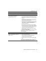
Troubleshooting . . . . . . . . . . . . . . . . . . . . . . . 85
Introduction . . . . . . . . . . . . . . . . . . . . . . . .
Problems and Solutions . . . . . . . . . . . . . . . . . .
Troubleshooting Flowcharts . . . . . . . . . . . . . . .
System Hardware and Power Troubleshooting Flowchart
GPS Reception Troubleshooting Flowchart . . . . . . .
OmniSTAR Troubleshooting Flowchart . . . . . . . . .
Thales Troubleshooting Flowchart . . . . . . . . . . . .
.
.
.
.
.
.
.
.
.
.
.
.
.
.
.
.
.
.
.
.
.
.
.
.
.
.
.
.
.
.
.
.
.
.
.
.
.
.
.
.
.
.
.
.
.
.
.
.
.
.
.
.
.
.
.
.
.
.
.
.
.
.
.
DSM 132/132RS Receiver User Guide
86
86
92
93
94
95
96
vii
Contents
B
Cables and Connectors . . . . . . . . . . . . . . . . . . . 97
Introduction . . . . . . . . . . . . . . . . . . . . . . . . . . . . . . . . . 98
Port A and Port B Connectors . . . . . . . . . . . . . . . . . . . . . . . 98
Standard Power/Data Cable . . . . . . . . . . . . . . . . . . . . . . . . . 99
C
NMEA-0183 Messages. . . . . . . . . . . . . . . . . . . 101
Introduction . . . . . . . . . . . . . . . . . . . . . . .
NMEA-0183 Message Structure . . . . . . . . . . . .
Symbols and delimiters . . . . . . . . . . . . .
Checksum values . . . . . . . . . . . . . . . . .
Field formats . . . . . . . . . . . . . . . . . . .
Null fields . . . . . . . . . . . . . . . . . . . .
Talker ID codes. . . . . . . . . . . . . . . . . .
Latitude and longitude values . . . . . . . . . .
Time values. . . . . . . . . . . . . . . . . . . .
Reading NMEA string format . . . . . . . . . .
NMEA Message Summary . . . . . . . . . . . . . . .
GGA (GPS Fix Data) . . . . . . . . . . . . . . . . . .
GLL (Position Data) . . . . . . . . . . . . . . . . . .
GRS (GPS Range Residuals) . . . . . . . . . . . . . .
GSA (GPS DOP and Active Satellites) . . . . . . . . .
GST (GPS PRN) . . . . . . . . . . . . . . . . . . . .
GSV (GPS Satellites in View) . . . . . . . . . . . . .
MSS (Beacon Receiver Signal Status) . . . . . . . . .
RMC (Recommended Minimum Specific GPS Data) .
VTG (Course Over Ground and Ground Speed) . . . .
XTE (Cross-Track Error) . . . . . . . . . . . . . . . .
ZDA (Time and Date). . . . . . . . . . . . . . . . . .
PTNLEV Proprietary (Event Marker). . . . . . . . . .
PTNLID Proprietary (Trimble Receiver ID) . . . . . .
PTNLDG Proprietary (Trimble DGPS Receiver Status)
PTNL,GGK (Time, Position, Position Type, and DOP)
viii
DSM 132/132RS Receiver User Guide
.
.
.
.
.
.
.
.
.
.
.
.
.
.
.
.
.
.
.
.
.
.
.
.
.
.
.
.
.
.
.
.
.
.
.
.
.
.
.
.
.
.
.
.
.
.
.
.
.
.
.
.
.
.
.
.
.
.
.
.
.
.
.
.
.
.
.
.
.
.
.
.
.
.
.
.
.
.
.
.
.
.
.
.
.
.
.
.
.
.
.
.
.
.
.
.
.
.
.
.
.
.
.
.
.
.
.
.
.
.
.
.
.
.
.
.
.
.
.
.
.
.
.
.
.
.
.
.
.
.
.
.
.
.
.
.
.
.
.
.
.
.
.
.
.
.
.
.
.
.
.
.
.
.
.
.
.
.
.
.
.
.
.
.
.
.
.
.
.
.
.
.
.
.
.
.
.
.
.
.
.
.
.
.
.
.
.
.
.
.
.
.
.
.
.
.
.
.
.
.
.
.
.
.
.
.
.
.
.
.
.
.
.
.
.
.
.
.
.
.
.
.
.
.
.
.
.
.
.
.
.
.
.
.
103
104
105
105
106
106
106
107
107
107
107
109
.111
.112
.113
.114
.115
.116
.117
.119
120
120
121
122
123
124
Contents
PTNLSM Proprietary (RTCM Special) . . . . . . . . . . . . . . . . . . 125
D
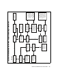
Navigation Maps . . . . . . . . . . . . . . . . . . . . . . 127
DSM132 Menu System . . . . . . . . . . . . . . . . . . . . . . . . . . 128
Navigation map for DSM 132 Receiver — Home,
Field Operations, and Status menus . . . . . . . . . . . . . 129
Navigation map for DSM 132 Receivers — Configuration
menu. . . . . . . . . . . . . . . . . . . . . . . . . . . . . 130
E
Specifications . . . . . . . . . . . . . . . . . . . . . . . 131
DMS 132 Receiver . . . . . . . . . . . . . . . .
Combined Antenna . . . . . . . . . . . . . . . .
GPS Channels . . . . . . . . . . . . . . . . . . .
Beacon Channels . . . . . . . . . . . . . . . . .
L-Band Satellite Differential Correction Receiver
Receiver Default Settings . . . . . . . . . . . . .
.
.
.
.
.
.
.
.
.
.
.
.
.
.
.
.
.
.
.
.
.
.
.
.
.
.
.
.
.
.
.
.
.
.
.
.
.
.
.
.
.
.
.
.
.
.
.
.
.
.
.
.
.
.
.
.
.
.
.
.
.
.
.
.
.
.
.
.
.
.
.
.
132
132
133
133
134
134
Index . . . . . . . . . . . . . . . . . . . . . . . . . . . . 137
DSM 132/132RS Receiver User Guide
ix
Contents
x
DSM 132/132RS Receiver User Guide
CHAPTER
1
Welcome
1
This manual describes how to install and configure the DSM™ 132
receiver. It provides guidelines for using the AgRemote utility to view
and configure receiver DGPS and communication operating
parameters. The manual also provides guidelines for connecting the
receiver to a variety of external devices, information about NMEA
messages supported by the receiver, and pin-out diagrams for data
cable connections.
Even if you have used other Global Positioning System (GPS)
products before, Trimble recommends that you spend some time
reading this manual to learn about the special features of this product.
If you are not familiar with GPS, go to the Trimble website
(www.trimble.com) for an interactive look at Trimble and GPS.
1.1
Related Information
Other sources of related information are:
•
Release notes – the release notes describe new features of the
product, information that is not included in the manuals, and
any changes to the manuals. You can download release notes
from the Trimble website.
DSM 132/132RS Receiver User Guide
11
1
1.2
Welcome
Technical Assistance
If you have a problem and cannot find the information you need in the
product documentation, contact your local dealer. Alternatively, do
one of the following:
•
1.3
Request technical support using the Trimble website at
www.trimble.com/support.html
Your Comments
Your feedback about the supporting documentation helps us to
improve it with each revision. E-mail your comments to
[email protected] you have a problem and cannot find
the information you need in the product documentation, contact your
local Trimble Reseller.
12
DSM 132/132RS Receiver User Guide
CHAPTER
2
Overview
2
In this chapter:
■
Introduction
■
The DSM 132 Receiver
■
Differential GPS (DGPS)
DSM 132/132RS Receiver User Guide
13
2
2.1
Overview
Introduction
This chapter describes the DSM 132 receiver and gives an overview of
GPS, DGPS, and related information. For details of the receiver
physical specifications, see Appendix E, Specifications.
2.2
The DSM 132 Receiver
The DSM 132 receiver combines high-performance GPS reception
with a DGPS-capable receiver in a lightweight, durable, waterproof
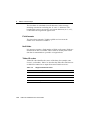
housing. The DSM 132 receiver also contains technology which
enables WAAS/EGNOS, OmniSTAR, Thales, or Coast Guard Beacon
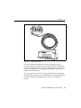
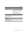
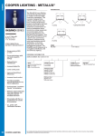
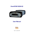
(MSK) real-time differential capabilities. See Figure 2.1.
When the connections described above are not available, the
DSM 132RS receiver has the capability to be used as a base station for
the generation of Differential GPS (DGPS) corrections. A radio link is
needed to broadcast the corrections to rover DSM 132 units.
14
DSM 132/132RS Receiver User Guide
Overview
Figure 2.1
2
DSM 132 receiver
As part of a marine construction or survey system, the receiver
provides submeter (less than 3.28 ft) precision whenever differential
corrections are applied. You can use a 1 PPS (pulse per second) strobe
signal to synchronize time for logging event markers when you are
using external instruments.
You can use the receiver with a variety of marine survey equipment,
including office software such as HYDROpro™, which also interfaces
with echo sounders and magnetometers, for use on waterborne
projects.
DSM 132/132RS Receiver User Guide
15
2
22.1
Overview
Standard features
A standard DSM 132 system provides:
•
12-channel L1 1575.42 MHz (C/A code) GPS receiver with
carrier phase filtering
•
Combined L1 GPS, Satellite differential, and beacon antenna
•
L-Band satellite differential correction capable receiver
Note – For the DSM 132 to operate with the L-Band
corrections, the client must subscribe to a satellite differential
service.
16
•
Dual-channel digital medium frequency beacon receiver
•
EVEREST™ technology for multipath rejection (firmware
version 1.73 and greater)
•
Differential correction input from other RTCM SC-104 sources
•
WAAS (U.S.A.) and EGNOS (Europe) differential capable
•
Sub-meter differential accuracy
•
2 line, 16 character liquid crystal display
•
4 button keyboard
•
1, 2, 5, and 10 Hz (10 positions per second) output messages
•
Operation manual
•
15m antenna cable
•
GPS receiver to PC cable
•
Magnetic mount for antenna
•
Two programmable RS-232 serial ports:
– NMEA-0183 output
– RTCM SC-104 input
– TSIP I/O
– Baud Rate 2400-38400
– 1 PPS (pulse per second) output
DSM 132/132RS Receiver User Guide
Overview
22.2
2
Standard Features DSM 132RS
A DSM 132RS system provides all the features of the DSM 132
except:
22.3
•
the L1 Geodetic antenna with ground plane is supplied
•
the 30 meter antenna cable is supplied
•
the RTCM SC-104 output (base station corrections) is available
Receiver enhancements
Table 2.1 lists the receiver options that you can purchase with the
DSM 132 receiver.
Table 2.1
Receiver enhancement options
Option (PN)
Description
Use
Differential
Base Station
(36429-30)
If a radio link is attached, enables the
Outputs RTCM differential
corrections. (This option is installed receiver to broadcast corrections for
use by other DGPS receivers. This
in the DSM 132RS.)
provides submeter positioning.
EVEREST
Technology
(36429-20)
Reduces multipath interference.
Improves DGPS receiver accuracy.
(This option is installed in receivers
with firmware version 1.73 and
greater.)
RTS/CTS
Flow Control
Negotiation
(36429-50)
Provides hardware flow control
When attached to third-party modems,
provides RTS/CTS flow control for
correct operation.
DSM 132/132RS Receiver User Guide
17
2
22.4
Overview
Receiver input / output
The DSM 132 standard power/data cable (PN 30945) connects to the
receiver ports to supply power. It also enables the following data
exchanges:
•
ASCII, TSIP, and RTCM input from an external device.
The receiver is able to receive ASCII data from an external
device, convert this data into an NMEA message, and export
that message to another device. TSIP command packets
configure and monitor GPS and DGPS parameters. The receiver
is also able to accept RTCM data from an external device, such
as a pager.
•
RTCM, TSIP, and NMEA to an external device.
The receiver is able to output RTCM in base station mode
(requires the base station option). When you are using an
external radio, it can also receive DGPS corrections. TSIP is
input/output when communicating with HYDROpro. NMEA is
output when the receiver is exporting GPS position information
to an external device or navigation software.
For more information on the NMEA (National Marine
Electronics Association) and RTCM (Radio Technical
Commission for Maritime Services) communication standard
for GPS receivers, go to the following websites:
•
–
www.nmea.org
–
www.rtcm.org
1 PPS output
To synchronize timing between external instruments and the
receiver’s internal clock, either one of the connection ports
outputs a strobe signal at 1 PPS (pulse per second). To output
this signal, the receiver must be tracking satellites and
computing GPS positions.
18
DSM 132/132RS Receiver User Guide
Overview
2.3
2
Differential GPS (DGPS)
The DSM 132 receiver uses DGPS to achieve high accuracy. You can
have a DSM 132RS (this is called the reference or base station)
located at a known point. This receiver is used to determine GPS
signal measurement errors. One or more mobile receivers (called
rovers) collect data at unknown locations, while remaining within
range of the reference station. The reference station broadcasts
correction values, which are applied to the receiver positions. In this
way, errors common to the reference and rover receivers are corrected.
For more information about DGPS and the different DGPS signals
available, visit the Trimble website
(www.trimble.com/gps/dgps.html).
23.1
Sources of GPS error
Autonomous (GPS only) horizontal accuracy for the Trimble
DSM 132 receiver ranges from approximately 2–9 meters (about 6–
30 ft).
The errors that cause this reduced accuracy are produced mainly by
atmospheric conditions, multipath error (that is, GPS signals bouncing
off objects before reaching the antenna), and electronic or GPS
frequency noise interference.
DGPS removes most of the errors caused by atmospheric conditions,
errors which are further minimized by the advanced design of the
DSM 132 receiver. For more information, see the section on Error
Correction on the Trimble website at
www.trimble.com/gps/errors1.html
DSM 132/132RS Receiver User Guide
19
2
Overview
DGPS accuracy
23.2
Submeter accuracy from the DSM 132 receiver utilizing differential
correction is best achieved under the conditions described in
Table 2.2.
Table 2.2
DGPS accuracy
Condition
Optimum
Value
Description
Number of
satellites used
>5
To calculate a 3D position (latitude and longitude, altitude,
and time), four or more satellites must be visible.
To calculate a 2D position (latitude and longitude, and time),
three or more satellites must be visible.
The number of visible satellites constantly changes and is
typically in the range 5–9. The DSM 132 receiver can track
up to 12 satellites simultaneously.
Note – To see when the maximum number of GPS satellites are
available, use the Quickplan utility and a current ephemeris
(satellite history) file. Both files are available free from:
www.trimble.com/support_trl.asp?Nav=Collection-3627
Maximum
PDOP
<4
Position Dilution of Precision (PDOP) is a unitless, computed
measurement of the geometry of satellites above the
receiver’s current location.
Note – In some agricultural applications that do not require high
accuracy, a maximum PDOP of 12 or more can be used.
Signal to Noise
Ratio
>6
Signal-to-Noise ratio (SNR) is a measure of the satellite
signal strength against electrical background noise. A high
SNR gives better accuracy.
Minimum
Elevation
> 7.5
Satellite that are low on the horizon typically produce weak
and noisy signals and are more difficult for the receiver to
track. Satellites below the minimum elevation angle are not
tracked.
Multipath
environment
Low
Multipath errors are caused when GPS signals are reflected
off nearby objects and reach the receiver by two or more
different paths. The receiver incorporates the EVEREST
multipath rejection option.
RTCMcompatible
corrections
20
These corrections are broadcast from a DSM 132RS or
equivalent reference station.
DSM 132/132RS Receiver User Guide
Overview
23.3
2
Position Output
Geographic data obtained from different sources must be referenced to
the same datum, ellipsoid, and coordinate format. Different formats
provide different coordinate values for any geographic location. In
North America, the datums NAD-27 and NAD-83 are commonly used
in marine applications.
The DSM 132 receiver outputs position coordinates in several datums
and ellipsoids depending on the source of DGPS being used. See
Table 2.3.
Table 2.3
DGPS source
Differential Source
Datum
Ellipsoid
1
None – Autonomous mode
WGS-84
WGS-84
OmniSTAR 3 North American Beams
NAD-832
–
OmniSTAR Rest of World Beams
ITRF3
GRS-80
Thales Beams
ITRF
GRS-80
WAAS Beams
WGS-84
WGS-84
1
World Geodetic System 1984. Datum and ellipsoid.
2
North American Datum 1983. Equivalent to WGS-84.
3
International Terrestrial Reference Frame. Contact the DGPS provider for details.
For more information, go to the National Geodetic Survey website:
www.ngs.noaa.gov/faq.shtml#WhatDatum.
Note – To convert GPS positions in the NAD-83 datum to background
maps for the old NAD-27 datum, use the conversion program
Corpscon. This is available free from the Topographic Engineering
Center (http://crunch.tec.army.mil/software/corpscon/corpscon.html).
DSM 132/132RS Receiver User Guide
21
2
Overview
Position Output Format
The DSM 132 receiver outputs positions in Degrees, Minutes, and
Decimal Minutes (DDD°MM.m'). This is the NMEA (National
Marine Electronic Association) standard format and is commonly
used worldwide for data transfer between electronic equipment.
23.4
Receiving beacon DGPS
To obtain free radiobeacon differential signals, the DSM 132 receiver
uses dual-channel, fully-automatic beacon receiver electronics and
tracks broadcasts that conform to the IALA (International Association
of Lighthouse Authorities) Standard. When you use beacon DGPS, the
receiver selects the closest of the 10 most powerful radiobeacons in
the vicinity. You can configure the receiver to search for particular
station frequencies, or use the EZ beacon feature to select local
beacons.
The receiver continuously monitors the integrity of the data received
from the differential radiobeacons. If it finds unacceptable errors in
the data stream, the receiver automatically switches to a different
radiobeacon, if one is available.
Radiobeacon signal reception is generally not affected by:
•
hilly or mountainous terrain
•
tree canopy
•
location of the receiver inside a canyon (the signal reception
depends on the proximity of the receiver to the transmitter)
Radiobeacon signal reception is affected to varying degrees, by:
22
•
natural “noise”, such as lightning
•
human-made “noise”, such as alternators, electric fan motors,
radio speakers, and high voltage power lines
•
Sky wave interference with ground wave
DSM 132/132RS Receiver User Guide
Overview
2
During darkness, when the beacon tower is more than
240–480 kilometers (150–300 miles) from the receiver, the sky
wave beacon signal may be reflected off the ionosphere. This
causes interference with the ground wave beacon signal. Selfjamming at night may be a problem with stronger beacon
stations.
•
Geographic de-correlation
This phenomenon causes radiobeacon signal accuracy to
decrease as the distance between the beacon tower and the base
station increases. Ionospheric conditions can affect accuracy by
as much as 1 meter (3 feet) for every 100 km (60 miles).
23.5
Receiving satellite DGPS
The DSM 132 receiver supports subscription-based OmniSTAR, and
Thales, satellite differential technology. Contact the service provider
for service activation or an encrypted activation passcode.
Note – For the DSM 132 to operate with these corrections, you must
subscribe to one of these services. The service provider may set
geographic limits on the use of its service.
In addition, the WAAS/EGNOS service is available free in North
America and Europe. For more information, see Configuring
Differential GPS, page 62, or go to the following websites:
•
OmniSTAR (www.omnistar.com)
•
Thales (www.landstar-dgps.com)
•
WAAS (http://gps.faa.gov/Programs/WAAS/waas.htm)
•
EGNOS (www.esa.int/export/esaSA/)
DSM 132/132RS Receiver User Guide
23
2
23.6
Overview
Receiving DGPS Corrections from Other Sources
The DSM 132 can also receive RTCM SC-104 corrections from
sources such as:
23.7
•
AM/FM carrier services
•
Your own radio data link (from a DSM 132RS reference
station)
Generating DGPS Corrections
In locations where MSK beacons or WAAS/EGNOS are not available,
or if you decide not to subscribe to L-band correction services, you
can install your own reference station and broadcast your own
corrections. The DSM 132RS or the firmware option for the DSM 132
allow corrections to be generated. A radio data link (UHF, VHF, and
so on) is required to transmit the corrections.
24
DSM 132/132RS Receiver User Guide
CHAPTER
3
Installing the Receiver
3
In this chapter:
■
System Components
■
Mounting the Receiver and Antenna
■
Routing and Connecting the Antenna Cable
■
Connecting to an External Device
■
Laptop Computer
DSM 132/132RS Receiver User Guide
25
3
3.4
Installing the Receiver
System Components
Check that you have received all the appropriate components for the
DSM 132 system that you have purchased. If any containers or
components are damaged, immediately notify the shipping carrier, or
Trimble Construction Division at the address given in the front of this
manual. Components for each system are listed in the following
tables.
Table 3.4
DSM 132 Receiver (PN 49086-00)
Qty
P/N
Description
1
33302-33
132 Receiver
1
33580-00
132 Antenna
1
12920-00
Magnetic Mount for Antenna
1
21555
15 m (50 ft) Ruggedized Antenna Cable
1
30945
Power/data Cable
1
50984-00
DSM Support CD (manuals, utilities)
Table 3.5
26
DSM 132RS Receiver (PN 49086-10)
Qty
P/N
Description
1
33302-33
DSM 132RS Receiver
1
36654-00
Compact L1 Antenna
1
11820-10
30 m (10 ft) Antenna Cable (N-N)
1
30945
Power/data cable
1
50984-00
DSM Support CD (manuals, utilities)
DSM 132/132RS Receiver User Guide
Installing the Receiver
34.1
Optional extras (if ordered)
Table 3.6
3.5
3
DSM 132 Receiver options
Qty
P/N
Description
1
36429-30
DGPS Base station Capability
1
36429-20
EVEREST Multipath Rejection Technology
1
36429-50
RTS/CTS Flow Control
Mounting the Receiver and Antenna
Mount the antenna in a clear position free from obstructions.
For some short term installations you can place the antenna upright
with the magnetic base on a flat metal surface.
35.1
Choosing a location
When choosing a location, consider the following:
Do mount the antenna:
•
on a flat surface along the centerline of the vessel.
•
in any convenient location within 15 meters (50 feet) of the
GPS receiver.
•
at the highest point of the vessel with no metal surfaces
blocking its view of the sky. Trimble recommends that you
position the antenna on the top of a mast or pole.
•
in such a way that it is not damaged when you sail under a
bridge.
Do not mount the antenna:
•
close to stays, electrical cables, metal masts, CB radio antennas,
cellular phone antennas, air-conditioning units, active TV
antennas, or machine accessory lights.
DSM 132/132RS Receiver User Guide
27
3
35.2
Installing the Receiver
•
near transmitting antennas, radar arrays, or satellite
communication equipment.
•
near areas that experience high vibration, excessive heat,
electrical interference, and strong magnetic fields.
The receiver
To mount the DSM 132 receiver:
4.
Drill four holes in the mounting surface. Use the slotted holes in
the mounting brackets as a template.
5.
Use screws to secure the brackets to the mounting surface.
Note – If you use machine screws, tap the mounting holes to
fasten the receiver to the mounting surface. Trimble
recommends that you use 8-32 UNF socket head cap screws.
Alternatively, use self-tapping screws.
30.1
The antenna
Mount the GPS antenna so that it has a clear view of the sky even
when the vessel is rolling. Ensure that it is safe from damage during
normal operation; that is, mount the antenna solidly for the worst-case
pitch, roll, and heave of the vessel.
The base of the rover antenna has a 1" UNC female thread. A steel
pipe with a male 1" UNC thread is a suitable pole mounting for the
antenna.
28
DSM 132/132RS Receiver User Guide
Installing the Receiver
30.2
3
Environmental conditions
Although the receiver has a waterproof housing, you should install it
in a dry location. To improve the performance and long-term
reliability of the receiver, avoid exposure to extreme environmental
conditions, including:
30.3
•
water
•
excessive heat (> 65°C or 149°F)
•
excessive cold (< –20°C or –4°F)
•
high vibration
•
corrosive fluids and gases
Electrical interference
As far as possible, when you install the receiver and antenna, you
should avoid placing them near sources of electrical and magnetic
noise, such as:
•
gasoline engines (spark plugs)
•
PC monitor screens
•
alternators, generators, or magnetos
•
electric motors (blower fans)
•
equipment with DC-to-AC converters
•
switching power supplies
•
radars
•
active marine TV antennas
•
CB radio antennas
•
cellular phone antennas
•
machine accessory lights
DSM 132/132RS Receiver User Guide
29
3
3.1
Installing the Receiver
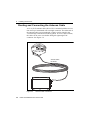
Routing and Connecting the Antenna Cable
A 15 m (50 ft) antenna cable (PN 21555) is included with the receiver.
One end is pre-terminated with a straight connector. The other end of
the antenna cable is not terminated, so that it can be routed in the
vessel through a minimal-sized hole (gland). If excess cable remains,
the cable can be cut to size before fitting the right-angle TNC
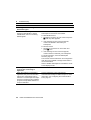
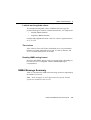
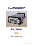
connector. See Figure 3.2.
Antenna cable
PN 21555
Figure 3.2
30
Antenna cable connections
DSM 132/132RS Receiver User Guide
Installing the Receiver
3
When routing the antenna cable, avoid the following hazards:
•
sharp objects
•
kinks in the cable
•
hot surfaces (exhaust manifolds or stacks)
•
rotating or moving machinery parts
•
sharp or abrasive surfaces
•
door and window jams
•
corrosive fluids or gases
After routing the cable, connect it to the receiver. Use tie-wraps to
secure the cable at several points along the route. One tie-wrap is
required to secure the cable near the base of the antenna. This provides
strain relief for the antenna cable connection.
When the cable is secured, coil any slack. Secure the coil with a
tie-wrap and tuck it into a safe place.
B
Tip – Use the tape (coax tape seal) that is provided with the antenna to
seal the antenna connector at the antenna. The tape prevents moisture
from entering the connection.
DSM 132/132RS Receiver User Guide
31
3
3.2
Installing the Receiver
Connecting to an External Device
After installing the receiver and antenna, connect and route the
power/data cable (PN 30945). The receiver can be powered by a
vehicle or by a customer-supplied 10–32 VDC power source.
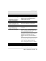
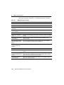
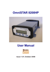
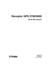
Figure 3.3 shows how to connect the receiver to an external device
using the 5.5 m (18 ft) standard power/data cable.
9–pin port
Antenna cable
DSM 132 receiver
AgGPS
124/
13
2
Cable 30945
Power
+ve
Red
Connect cable 30945
to Port A
Figure 3.3
32
Ground
–ve
Black
-
Standard power/data cable connections
DSM 132/132RS Receiver User Guide
Installing the Receiver
3
Plug the:
•
right-angle connector into the receiver
•
straight 9-pin connector into the external device (such as a PC
running HYDROpro software).
When routing the cable from the receiver to the external device, avoid
the hazards listed on page 31.
When the cable is safely routed and connected to the receiver, use
tie-wraps to secure it at several points, particularly near the base of the
receiver to prevent straining the connection. Coil any slack cable,
secure it with a tie-wrap, and tuck it into a safe place.
DSM 132/132RS Receiver User Guide
33
3
3.3
Installing the Receiver
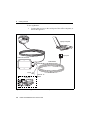
Laptop Computer
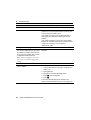
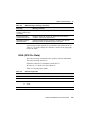
Figure 3.4 shows how to connect the receiver power/data cable to a
laptop computer.
Laptop computer
9–pin port
DSM132 Receiver
AgGPS
124/
13
2
Cable 30945
Power
+ve
Red
Connect cable 30945
to Port A
Figure 3.4
34
Ground
–ve
Black
Connecting the receiver to a laptop computer
DSM 132/132RS Receiver User Guide
CHAPTER
4
Getting Started
4
In this chapter:
■
Introduction
■
Front Panel
■
The AgRemote Menu System
■
Using AgRemote
■
Navigating the Menus and Screens
■
Menu System Fields
■
The Home Screen
■
Updating the Firmware
DSM 132/132RS Receiver User Guide
35
4
4.1
Getting Started
Introduction
This chapter describes how to set up and begin using the DSM 132
receiver.
4.2
Front Panel
The DSM 132 receiver includes an integrated display and keypad for
accessing the internal menu system. Use the menus and screens in this
system to configure the receiver settings and review receiver status. To
view the entire menu system, see Appendix D, Navigation Maps. You
can also access the menu system using office computer software, such
as AgRemote.
Figure 4.1 shows the LCD display and keypad on the DSM 132
receiver front panel.
LCD display
Enter
Up
Down
Keys
Figure 4.1
36
DSM 132 receiver front panel
DSM 132/132RS Receiver User Guide
Right
Getting Started
42.1
4
Installing AgRemote
AgRemote requires Microsoft® Windows® 95, 98, Me,
Windows 2000, or XP.
To install the latest version of AgRemote:
1.
Download the AgRemote software from the Trimble website
(www.trimble.com/aggps132_ts.asp?Nav=Collection-4361).
2.
Follow the prompts provided by the File Download wizard:
a.
Select Save this program to disk.
b.
Click OK.
Save the AgRemote file to My Documents, or to another folder
of your choice on the hard drive of your computer. Click Save.
The download takes about a minute, depending on your Internet
connection speed.
3.
Select the folder where you saved the AgRemote file.
4.
Double-click the downloaded file to start installing AgRemote.
5.
In the InstallShield dialog, click Yes.
6.
Follow the instructions provided by the installation wizard.
When completed, click Finish.
DSM 132/132RS Receiver User Guide
37
4
Getting Started
To use AgRemote:
1.
Connect the receiver to the serial port of the office computer, as
shown in Figure 4.2.
Laptop computer
9–pin port
DSM 132 Receiver
AgGPS
124/
13
2
Cable 30945
Power +ve
Red
Connect cable 30945
to Port A
Figure 4.2
38
Ground -ve
Black
Connecting the receiver to an office computer
DSM 132/132RS Receiver User Guide
Getting Started
2.
From the
3.
When the program starts, select File / Connect.
4
menu, select Programs / AgRemote / AgRemote.
AgRemote establishes communication with the receiver and
displays the Home screen of the AgGPS menu system, as shown
in Figure 4.3.
Home screen
S
V08 DOP02
D 3D
S
S 1554.4970 /N 10
Esc
Enter
Up
Down
Right Left
Keys
Figure 4.3
4.
AgRemote window and navigation keys.
Navigate to the required screen. Use the display to configure the
communication ports, differential correction source, and/or
AgGPS® lightbar communication settings. For a map showing
the full menu system, see Appendix D, Navigation Maps. For
more information, see Chapter 5, Configuring the Receiver.
DSM 132/132RS Receiver User Guide
39
4
4.1
Getting Started
The AgRemote Menu System
Use the commands provided by the AgGPS menu system to:
•
monitor the receiver status
•
change the receiver configuration
This section describes the menu system and the setting display
options. Chapter 5, Configuring the Receiver, describes how to
configure the receiver using the menu system.
4.2
Using AgRemote
To configure and monitor the receiver:
1.
Connect the receiver to the office computer running AgRemote.
See page 38.
2.
Switch on the receiver.
3.
Click
, then select Programs / AgRemote / AgRemote.
When the Home screen appears, you can press 1 or 3 to access
other screens in the AgGPS menu system.
Srch í00 DOP00
S 1556.0000 Srch
B
40
Tip – Use the navigation maps in Appendix D, Navigation Maps as a
reference when navigating the DSM 132 menu system.
DSM 132/132RS Receiver User Guide
Getting Started
40.1
4
The AgRemote keys
The actions of the AgRemote keys depend on whether a menu or
screen is displayed. Table 4.1 describes the key actions.
Table 4.1
Key actions
Key
Action if menu displayed
Action if screen displayed
Return to the top of the menu when an
Exit screen appears after the last
screen in a menu.
From the Home screen, change Satellite
DGPS source mode.
From the Lock Display Cfg screen, display
the Enter Password screen.
From other screens, perform an action
associated with that screen.
Move down a menu level.
Display the first screen from a lower
level menu.
Move up a menu level.
Move downward through the screens in a
menu.
Move downward through the list of options in
multiple-choice fields.
Move upward through the screens in a
menu.
Move upward through the list of options in
multiple-choice fields.
Move horizontally through the upperand lower-level menus.
Select the next alphanumeric or
multiple-choice field on a screen. When
Move from the last upper-level menu to alphanumeric or multiple-choice fields are
available, the
symbol appears in the
the Home screen.
corner of the screen.
Move to the next letter or digit of a field.
Move up one menu level.
Ultimately, return to the Home screen.
Move from a screen to the screen’s menu.
Press again to return to the previous level.
Press again to return to the Home screen.
DSM 132/132RS Receiver User Guide
41
4
4.1
Getting Started
Navigating the Menus and Screens
Note – Use a menu to navigate to screens or other menus. Use a
screen to view the receiver status or to change a configuration setting.
The top level of the AgRemote menu system consists of the Home,
Field Operations, Status, and Configuration menus. Each of these has
one or more lower level menus (sub-menus), which you can use to
access screens for selecting options, viewing status information, and
entering data. For a map showing the full menu system, see
Appendix D, Navigation Maps.
When you are using the receiver front panel keypad to navigate the
menu system, press 2+1 simultaneously to move to the previous
menu. Press and hold (or press repeatedly) 2+1 simultaneously to
return to the Home screen.
42
DSM 132/132RS Receiver User Guide
Getting Started
4
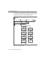
Figure 4.4 shows the structure of a typical sub-menu, such as Display
Options.
Home
Top-level menu screen
1
2
Display
Options
Sub-menu screen
2
1
Units
Contrast
Screens
1
2
1
Clear
Memory
Lock
Display
1
2
1
Exit screen indicates
end of the menu
Figure 4.4
2
2
Update
Receiver
Language
1
2
1
2
Exit
Typical menu structure
Press 2 or 1 to move between screens.
Within screens, select options, view receiver status, or enter data.
When Ð appears in a screen, press 4 to perform the action specified
for that screen.
DSM 132/132RS Receiver User Guide
43
4
4.2
Getting Started
Menu System Fields
Fields in a screen contain status information or configuration settings.
Information or settings can appear in fields that are:
42.1
•
display-only
•
multiple-choice
•
alpha, numeric, or alphanumeric
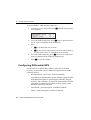
Display-only fields
A display-only field shows status information and other data that is
automatically generated by the receiver or acquired from satellite
signals. You cannot edit this field. Examples include fields that display
the DGPS data on the Home screen and the fields in the screen in
Figure 4.5, which show details of the current receiver options.
Receiver option details field
Figure 4.5
42.2
Example of a display-only field
Multiple-choice fields
In a mulitple-choice field, you select one option from a list. Only one
option can appear in the field at one time. Press 3 to select a
multiple-choice field, the press 2 or 1 to move through the list.
When the required option appears, press 4 to select it and save the
changes.
44
DSM 132/132RS Receiver User Guide
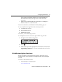
Getting Started
4
Examples include the two multiple-choice fields that appear in the EZ
Sat DGPS Configuration screen (see Figure 4.6). These are the fields
which list available satellite providers and satellite coverage beams.
Service Provider field
Satellite Coverage Beam field
Figure 4.6
42.3
Example of a multiple-choice field
Alpha, numeric, and alphanumeric fields
In these fields, you can enter only letters (alpha screens), only
numbers (numeric screens), or a combination of the two
(alphanumeric screens):
1.
Press 3 to select the field and activate the cursor on the first
letter or number.
2.
Press 1 or 2 to move through the list of letters or numbers
until the required letter or number appears.
3.
Press 3 to move to the next place in the field.
4.
Repeat steps 2 and 3 to enter all required characters.
5.
Press 4 to save the changes.
DSM 132/132RS Receiver User Guide
45
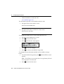
4
Getting Started
One example of a numeric field appears in the Satellite Freq screen. In
this field, you manually enter the broadcast frequency of a satellite
service provider. See Figure 4.7.
Satellite Frequency field
Figure 4.7
4.1
Example of a numeric field
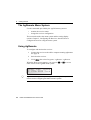
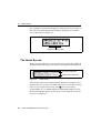
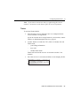
The Home Screen
When you start AgRemote, or access the receiver using the AgGPS 70
Remote Display and Logger, the Home screen appears. See Figure 4.8.
Srch í00 DOP00
S 1556.0000 Srch
Figure 4.8
GPS status indicators
Satellite DGPS indicators
Home screen
You can leave this screen running during operation. It enables you to
monitor the receiver status. To return to the Home screen after viewing
other receiver menus and screens, press 5 one or more times.
As the DSM 132 is a combined Beacon and Satellite DGPS receiver,
the information that appears on the Home screen depends on how the
receiver is configured.
46
DSM 132/132RS Receiver User Guide
Getting Started
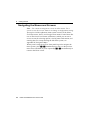
41.1
4
Satellite DGPS mode
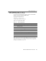
In this manual, references to Satellite DGPS apply only to the
DSM 132 receiver. When the receiver is in Beacon DGPS mode, a B,
Beacon Searching, Beacon Tracking, or Beacon FFT message appears in the
lower-left corner of the screen. To change between modes, press 4
and hold for five seconds. To display satellite differential information,
press 4 until an S appears in the lower left corner of the screen.
41.2
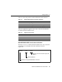
Satellite and WAAS/EGNOS DGPS mode
The DSM 132 can receive Beacon, L-band, and WAAS/EGNOS
DGPS signals. The Home screen indicates which mode the receiver is
in for differential correction.
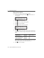
Figure 4.9 explains the GPS status indicators that can appear on the
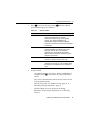
first line of the Home screen display.
D/3D í07
DOP03
Current PDOP value
Number of GPS satellite vehicles (SVs) being
tracked
Position Type
Figure 4.9
GPS status
DSM 132/132RS Receiver User Guide
47
4
Getting Started
Table 4.2 explains the indicators that can appear in the Position Type
field.
Table 4.2
Position types
Display
Description
SRCH
Searching for satellites.
TRCK
Tracking satellites.
G/2D
Outputting 2-dimensional autonomous positions.
G/3D
Outputting 3-dimensional autonomous positions.
D/2D
Outputting 2-dimensional differential positions.
D/3D
Outputting 3-dimensional differential positions.
Note – The “/” symbol in the position type spins when the receiver is
operating correctly.
Satellite DGPS mode status indicators
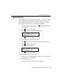
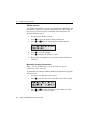
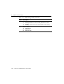
When the receiver is in Satellite mode, the second line of the Home
screen displays the status indicators shown in Figure 4.10.
S
1556.2550 ÷ø10
Signal-to-noise ratio of DGPS
signal, see Table 4.4
Frequency for tracked DGPS satellite. Available
frequencies vary according to your location and
DGPS service provider.
Receiver is using Satellite DGPS corrections.
Figure 4.10
48
Satellite DGPS mode status indicators
DSM 132/132RS Receiver User Guide
Getting Started
4
Table 4.3 shows the possible satellite differential mode indicators.
Table 4.3
Satellite differential mode status indicators
Indicator
Description
S ####.### S/N ##
Operating in Satellite Differential mode.
S SRCH ###.##
Searching for Satellite Differential signal.
S TRCK ####.##
Tracking satellite without acquiring signal lock.
Table 4.4 explains the signal-to-noise ratio values for both Satellite
and WAAS/EGNOS DGPS modes.
Table 4.4
Signal-to-noise values
Value
Description
Below 4
Unusable
4–8
Fair
>8
Excellent
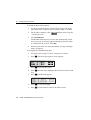
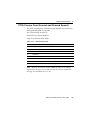
WAAS/EGNOS DGPS mode status indicators
When the receiver is in WAAS/EGNOS DGPS mode, the second line
of the Home screen displays the status indicators shown in
Figure 4.11.
WAAS
122
÷ø07
Signal-to-noise ratio of DGPS signal, see
Table 4.4
WAAS satellite ID
Receiver is using WAAS/EGNOS corrections.
Figure 4.11
WAAS DGPS mode status indicators
DSM 132/132RS Receiver User Guide
49
4
41.3
Getting Started
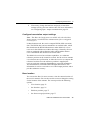
Beacon DGPS mode
When in Beacon DGPS mode, the Home screen displays “B” (Beacon
DGPS) in the lower left corner. Figure 4.12 explains the status
indicators that appear on the first line of the Home screen display
when the receiver is in this mode.
B
B
A-R
÷ø15
A-R 310.0
310.0
÷ø15
The beacon signal-to-noise
ratio. S/N values range from 0
to 30. High numbers are best.
Above 6 is acceptable.
The beacon frequency. Frequency varies
depending upon the beacon used.
The beacon operating mode.
Indicates the receiver is using beacon DGPS.
Figure 4.12
Beacon DGPS status
Table 4.5 describes messages that can appear when the receiver is in
Beacon DGPS mode.
Table 4.5
50
Beacon DGPS operating mode messages
Message
Description
B
The receiver is operating in Beacon mode.
Beacon Searching
The receiver is searching for beacon signals.
Beacon Tracking
The receiver is tracking beacon signals and is
attempting to gain lock.
Beacon Idle
Beacon DGPS is not active.
DSM 132/132RS Receiver User Guide
Getting Started
Table 4.5
4.2
4
Beacon DGPS operating mode messages (continued)
Message
Description
Beacon FFT
The receiver is looking for a beacon across the
signal spectrum.
Beacon Disabled
Beacon DGPS is disabled in the receiver. You will
need to change configuration settings to enable
Beacon DGPS.
External RTCM
Differential corrections are being provided by an
external source, through port A or port B.
Battery is Low
This warning replaces the DGPS information when
the input voltage is low.
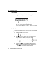
Updating the Firmware
To update the receiver firmware when a new version is released:
1.
Download the upgrade files.
2.
Install the FlashLoader100 utility.
3.
Connect the receiver to an office computer.
4.
Upgrade the firmware from the office computer, using the
upgrade files.
For full details of how to do this, refer to the Release Notes provided
with your receiver firmware.
If you have problems when you update the firmware, see Appendix A,
Troubleshooting. For further assistance, contact your local Trimble
Reseller.
DSM 132/132RS Receiver User Guide
51
4
52
Getting Started
DSM 132/132RS Receiver User Guide
CHAPTER
5
Configuring the Receiver
5
In this chapter:
■
Introduction
■
Display Options
■
Configuring the Communication Ports
■
Configuring Differential GPS
■
Paid Subscription Services
■
WAAS/EGNOS
■
Configuring Beacon DGPS
■
Configuring Other DGPS Corrections
■
Configuring DGPS Base Station
DSM 132/132RS Receiver User Guide
53
5
5.1
Configuring the Receiver
Introduction
The Display Options, Satellite Differential Source, and Port
Communication parameters must be specific to your particular use, so
they are not preset. You only need to configure the receiver once, as
the settings you choose are saved to permanent memory.
B
Tip – Refer to Appendix D, Navigation Maps while navigating the
DSM 132 menu system.
To change the receiver configuration settings, connect the receiver to
AgRemote. For more information, see Getting Started, page 35
The following sections describe how to change the receiver settings.
5.2
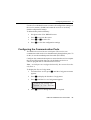
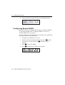
Display Options
Use the Display Options menu to control how information is displayed
in the screens that you can access from the Field Operations, Status
and Configuration menus.
To view the Display Options menu:
•
54
From the Home screen (see page 46), press 2:
DSM 132/132RS Receiver User Guide
Configuring the Receiver
5
Setting the language
To change the language used for display:
1.
Navigate to the Language screen:
2.
Press 3 to select the Language field.
3.
Press 1 or 2 until the required language is displayed.
4.
Press 4 to select it and save the changes.
5.
Press 5 to return to the Display Options menu.
The screen automatically displays the selected language.
Setting the units
The Units screen displays U.S., Metric, or Nautical units in the screens
that you access from the Field Operation, Status, and Configuration
menus.
Note – This setting does not affect GPS position data output.
1.
Navigate to the Units screen:
2.
Press 3 to select the Units field.
3.
Press 1 or 2 until the required unit is displayed.
4.
Press 4 to select it and save the changes.
5.
Press 5 to return to the Display Options menu.
6.
Press 5 again to return to the Home screen.
DSM 132/132RS Receiver User Guide
55
5
Configuring the Receiver
Locking the Configuration menus
To prevent unauthorized changes to the configuration, you can lock
the Configuration menus:
1.
Navigate to the Lock Display Cfg screen.
2.
Press 4 to display the Enter Password screen. The cursor is
active on the first digit:
3.
Use the last five numbers of the receiver serial number as the
password (“passcode”).
Press 1 or 2 until the first digit of the serial number appears.
4.
Press 3 to select the next digit. Repeat step 3 until all five
digits are entered.
5.
Press 4 to save the changes.
The Valid Password message appears, and the Configuration
menus are no longer displayed when you navigate the menus.
If the message Invalid Password appears, enter the password again.
B
Tip – When the Configuration menus are locked, you can view most
Configuration menu settings from the Status menus.
To unlock the Configuration menus, repeat the above procedure.
Clearing battery-backed RAM
C
56
Warning – When you select the Clear BB Ram option, any changes that
you have made in the Configuration menus are deleted and cannot be
restored.
DSM 132/132RS Receiver User Guide
Configuring the Receiver
5
Use the Clear BB RAM screen to remove all configuration settings in
the receiver memory (RAM) and return the receiver to its factory
default configuration settings:
To delete battery-backed memory:
5.1
1.
Navigate to the Clear BB RAM screen:
2.
Press 3 to activate the cursor.
3.
Press 1 or 2 to select Yes.
4.
Press 4 to clear the configuration settings.
Configuring the Communication Ports
The DSM 132 receiver has two serial ports. The receiver can
communicate with two devices simultaneously through these ports. To
do this, it uses the standard power/data cable (PN 30945).
Configure the communication ports to ensure that the receiver outputs
the correct GPS position data type, for the hardware device or
software program that is connected to the receiver.
Note – As both ports are configured identically, this section describes
only Port A.
To display the Port A Config menu:
1.
From the Home screen, press 3 until the Configuration menu
appears.
2.
Press 2 to display the Guidance Config menu.
3.
Press 3 until the Port A Config menu appears:
Port A Config
Press v to Enter
4.
Press 2 to move through the screens as required.
DSM 132/132RS Receiver User Guide
57
5
Configuring the Receiver
The following section describes how to configure the appropriate Port
A Config screens. The menu for Port B is identical. Figure 5.13 shows
the menu that you use to access the configuration screens.
Configuration
2
(Guidance Config
3 Lightbar Config 3 ) Func Key Config 3
Log Config (RDL) 3 GPS Config 3
Port A
Config
DGPS Config 3
2
1
Port A
In/Out
1
NMEA 3
Messages
2
Port A Out
RTS/CTS
1
2
NMEA 1
Messages
1
2
NMEA 2
Messages
1
Figure 5.13
58
Port A Config menu
DSM 132/132RS Receiver User Guide
2
2
1
NMEA/TSIP
Output Rate
1
2
1 Hz NMEA
1
2
Exit
Configuring the Receiver
50.1
5
Configuring input / output communication
Configure the Port Input/Output communication settings for
communicating with other external hardware devices, and software
programs. Table 5.6 describes the input settings.
Table 5.6
Port input settings
Setting
Description
None
Inputs nothing to the receiver.
TEXTB
The receiver can accept ASCII data from an external device,
such as a chlorophyll meter, on Port A, merge it with NMEA GPS
data, and output the combined data on Port B. The incoming data
must be limited to 66 ASCII characters and must be terminated
by a carriage return and line feed (hex characters 0x0D 0x0A).
The NMEA string outputs as $PTNLAG001,<up to 66 ASCII
characters>*<2 digit checksum><CR><LF>. For the receiver to
output the combined NMEA string, NMEA must be selected as
the output protocol on Port B.
TEXTA
See the description for the TEXTB setting. TEXTA outputs on
Port A, not Port B.
RTCM
The receiver can accept RTCM data from an external DGPS
device, such as an FM pager, or DSM 132RS and radio data link.
TSIP
The receiver can accept or output TSIP data packets from the
port when using the optional AgRemote program or HYDROpro
software.
LBAR
Not used for marine applications.
The default values for the other port settings are:
Port A
Baud rate
In
RTCM 9600
Out
NMEA 4800
Port B
Data bits
8
8
Parity
None
None
Stop bits
1
1
DSM 132/132RS Receiver User Guide
59
5
Configuring the Receiver
When setting the baud rate, note the following:
•
If you are using 19.2 k or 38.4 k, the input rate must match the
output rate.
•
If Port A is operating at 19.2 k, Port B can operate at 1200,
2400, 9600, or 19.2k (not 38.4 k).
•
If Port B is operating at 38.4k, Port A can operate at 1200, 2400,
9600 and 38.4k (not 19.2k).
To change the input or output settings:
1.
From the Port A Config screen, press 2 until the Port-A
Input/Output screen appears:
åæ
8N1
I RTCM 9600
0 NMEA 4800
2.
Press 3 to activate the cursor.
3.
Press 1 or 2 to change the value.
4.
Press 3.
5.
Repeat steps 3 and 4 until you have set all the required values.
6.
Press 4 to save all the changes.
7.
Press 2 to move to the next screen.
Selecting NMEA messages for output
Use this screen to select the NMEA messages output from the current
port. Only upper-case NMEA message types are output. The default
messages are GGA, GSA, VTG, and RMC.
60
DSM 132/132RS Receiver User Guide
Configuring the Receiver
5
To select the NMEA messages for output:
1.
From the Port A Config menu, press 2 until the NMEA1
screen appears:
åæ NMEA1 GGA gll
grs GSA gst gsv
2.
Press 3 to activate the cursor on the first NMEA message
type.
3.
Press 1 or 2 until the NMEA message type appears in upper
case.
4.
Press 3 to select the next message type.
5.
Repeat steps 4 and 5 until all the message types that you want to
output appear in upper-case.
6.
Press 4 to save the changes.
7.
Repeat this operation as required in the other NMEA screens.
For detailed information about the content and structure of NMEA
messages, see Appendix C, NMEA-0183 Messages.
Port output rate
Use the Message Rate screen to vary the NMEA and TSIP output rate.
The default setting is 01 (1 Hz, or 1 position per second).
You can select faster output rates, such as 2, 5, or 10 positions per
second.
Note – Select ASAP if you want the output rate to be the same as the
output rate selected on the Position Rate screen under the GPS Config
menu.
DSM 132/132RS Receiver User Guide
61
5
Configuring the Receiver
To set the NMEA / TSIP message output rate:
1.
From the Port A Config menu, press 2 until the Message Rate
screen appears:
åæNMEA out
TSIP out
5.1
01 s
01 s
2.
To set the NMEA output rate, press 3 twice to place the active
cursor on the second digit of the NMEA line.
3.
Press:
a.
2 to set the output rate to ASAP.
b.
1 to increase the output rate by one second. Press this key
as often as necessary, to a maximum of 99 seconds.
4.
To set the TSIP output rate, press 3 twice to move the cursor
to the second digit of the TSIP line. Repeat step 3.
5.
Press 4 to save the changes.
Configuring Differential GPS
For the receiver to output GPS position coordinates of submeter
accuracy, you must first select a differential signal from one of the
following sources:
•
WAAS/EGNOS – free service, limited availability
The Wide Area Augmentation System (WAAS) augments GPS
with additional signals for increasing the reliability, integrity,
accuracy, and availability of GPS in the United States. EGNOS
(European Geostationary Navigation Overlay System) is the
European equivalent of WAAS.
62
•
OmniSTAR – paid subscription, available worldwide
•
Thales – paid subscription, available worldwide
DSM 132/132RS Receiver User Guide
Configuring the Receiver
5
You can use one of these paid services as an alternative to
WAAS/EGNOS. They both provide over-the-air DGPS
activation.
•
Other source of RTCM SC-104 corrections; for example, a
DSM 132RS over a radio data link.
For more information, see Differential GPS (DGPS), page 19.
To use the differential signal from the selected provider:
1.
Configure the receiver.
2.
Activate the receiver.
3.
Enable the receiver.
For details, see the following sections.
To configure the receiver to receive signals from any provider:
5.1
1.
Navigate to the DGPS Config menu:
2.
Press 2.
3.
Follow the steps in the appropriate section below. Each section
describes how to configure, activate, and enable the receiver for
a particular provider.
Paid Subscription Services
When you obtain a paid satellite subscription, contact the service
provider for the correct satellite coverage beam for your geographic
location.
In the U.S. and Canada, contact:
•
OmniSTAR at 1- 888-883-8476
www.omnistar.com
DSM 132/132RS Receiver User Guide
63
5
Configuring the Receiver
•
Thales-LandStar at 1-888-434-7757
www.landstar-dgps.com/
You will need to provide a serial number and user code:
1.
Navigate to the Serial number screen.
Note the serial number here:
2.
Navigate to the Omni* or Thales Srv Info screen.
Note the user code here:
To configure the DGPS Source for the subscription service:
1.
Navigate to the DGPS Source screen.
2.
Press 3 to activate the cursor.
3.
Press 2 until Satellite Only appears:
4.
Press 4 to save the changes.
5.
Press 5 to return to the DGPS Config menu.
To configure the provider name and the correct satellite coverage
beam:
1.
From the DGPS Config menu, press 2 until the EZ Sat screen
appears.
Note – The EZ Sat screen includes the Coverage Beam field and
the Geographic Location field.
2.
64
Press 3 to activate the cursor.
DSM 132/132RS Receiver User Guide
Configuring the Receiver
50.1
5
3.
Press 2 until the required provider appears (Omni* or Thales).
4.
Press 3 to move to the next field.
5.
Press 2 until the coverage beam for your location appears.
6.
Press 4 to save the changes.
7.
Press 5 to return to the DGPS Config menu.
OmniSTAR
To activate OmniSTAR DGPS:
1.
Switch on the receiver and make sure it is configured for the
correct satellite coverage beam.
If you do not know the coverage beam for your location, contact
OmniSTAR, see Paid Subscription Services, page 63.
2.
Contact OmniSTAR on 1-888-883-8476 (USA or Canada).
Provide OmniSTAR with:
–
your billing information
–
user code
–
satellite beam name
OmniSTAR will activate the receiver. Activation can take
5–30 minutes.
3.
Once the receiver is activated, the Home screen displays D/3D:
DSM 132/132RS Receiver User Guide
65
5
Configuring the Receiver
If automatic activation fails, try to activate OmniSTAR DGPS
manually, as described below. If you cannot activate the OmniSTAR
differential service, contact your local Trimble Reseller.
Activating OmniSTAR manually
Note – If the receiver is activated automatically, this option is not
available.
If over-the-air activation fails, or if you want to activate the
OmniSTAR differential service manually, obtain an activation code
from OmniSTAR:
1.
Contact OmniSTAR for the activation code and satellite
coverage beam for your location. See Paid Subscription
Services, page 63. You will need to provide a serial number.
Note the activation number here:
Note the satellite coverage beam here:
2.
From the DGPS Config screen, press 2 until the Omni* screen
appears:
åæ Press Ð for
Omni* Activation
66
3.
Press 4 twice. In the screen that appears, the active cursor
highlights the first digit.
4.
Press 1 or 2 to change the number.
5.
Press 3 to select the next digit.
6.
Repeat steps Step 4 and Step 5 to enter all 24 numbers.
7.
Press 4 to save the changes.
8.
Press 5 to return to the DGPS Config menu.
DSM 132/132RS Receiver User Guide
Configuring the Receiver
5
Note – If you enter an incorrect code, try again using the correct
numbers. An incorrect code has no effect on receiver operation.
50.1
Thales
To activate Thales DGPS:
1.
Switch on the receiver and make sure it is configured for the
correct satellite coverage beam.
If you do no know the coverage beam for your location, contact
Thales, see Paid Subscription Services, page 63.
2.
Contact Thales at 1-888-434-7757 (USA or Canada). Provide
Thales with:
–
your billing information
–
user code
–
satellite beam name
Thales will activate the receiver. Activation can take 5–60
minutes.
3.
Once the receiver is activated, the Home screen displays D/3D:
D/3D ß07 DOP03
S 1556.2550 ÷ø10
DSM 132/132RS Receiver User Guide
67
5
Configuring the Receiver
Thales reference stations
To manually select a Thales network reference station:
1.
From the DGPS Config screen, press 2 until the Thales Stn
screen appears:
åæ Thales Stns
Use Network Stn
2.
Press 3 to activate the cursor.
3.
Press 2 until Use Manual Mode appears.
4.
Press 4 to save the changes.
5.
Press 2 until Thales Man Stns appears:
åæThales Man Stn
565
No access
6.
Press 3 to activate the cursor.
7.
Press 2 until the correct station appears for the satellite beam
you are using. Trimble strongly recommends the stations listed
below.
If you are using the
satellite beam ...
with this
frequency ...
select this
reference station ...
North American West
1556.255
565
North American Mountain
1554.350
555
North American East
1553.345
555
Note – Before you can select a reference station, you must have
a current subscription to the Thales DGPS service.
8.
68
Press 4 to save the changes.
DSM 132/132RS Receiver User Guide
Configuring the Receiver
5.1
5
WAAS/EGNOS
WAAS/EGNOS is a free satellite-based DGPS service that is available
only in North America (WAAS) or Europe (EGNOS). To use the
WAAS/EGNOS DGPS signal, you must first configure the receiver.
To configure the receiver to use WAAS/EGNOS DGPS:
1.
From the DGPS Config menu, press 2 until the DGPS Source
screen appears.
2.
Press 3 to activate the cursor.
3.
Press 2 until WAAS/EGNOS ONLY appears:
åæ DGPS Source
WAAS/EGNOS ONLY
4.
Press 4 to save the changes.
To enable the WAAS/EGNOS DGPS signal:
1.
Press 2 until the WAAS/EGNOS T2 Remap screen appears.
2.
Press 3 to activate the cursor.
3.
Press 2 until On appears:
åæ WAAS/EGNOS
T2 Remap On
4.
Press 4 to save the changes.
To enable WAAS reception in the field:
1.
Take the receiver outside. Make sure that it has a clear southeast
and southwest view of the sky.
2.
Switch on the receiver.
WAAS activation can take two or more minutes.
DSM 132/132RS Receiver User Guide
69
5
Configuring the Receiver
3.
Once activation succeeds, the Home screen displays D/3D:
D/3D
WAAS
5.1
í07 DOP03
122 ÷ø04
Configuring Beacon DGPS
DSM 132 receivers are configured by default to use WAAS/EGNOS
in Auto Range DGPS mode. To change a DSM 132 receiver to
Satellite DGPS mode, see page 66.
Select the frequency of the channels to be used when receiving RTCM
SC-104 broadcasts from radiobeacons:
70
1.
Navigate to the DGPS Source screen.
2.
If the screen does not display Beacon Only, press 3 to select
the Data Source field. Then press 2 until Beacon Only
appears.
3.
Press 4 to save the changes.
4.
Press 2 until the Beacon Mode screen appears:
DSM 132/132RS Receiver User Guide
Configuring the Receiver
5.
Press 3 to activate the cursor. Press 2 until the required
beacon mode appears. See Table 5.7.
Table 5.7
6.
5
Beacon modes
Mode name
Description
Auto Range mode
Reads the incoming RTCM SC-104 message
stream and selects the two closest
radiobeacons within range of the AgGPS
receiver. The closest radiobeacon is
automatically assigned to Beacon DGPS
Channel 0, and the second closest is assigned
to Channel 1.
Auto Power mode
Detects the signal strength of the two most
powerful radiobeacons within range of the
DSM 132 receiver. The most powerful
radiobeacon is automatically assigned to
Beacon DGPS Channel 0, and the second is
assigned to Channel 1.
Disabled mode
Disables DGPS and forces the DSM 132
receiver to operate in GPS mode only.
Manual Freq mode
Disables the automatic selection of
radiobeacons so that you can manually select
the frequency of radiobeacons for Channel 0
and 1.
If you selected:
–
Auto Range Mode or Auto Power Mode, configuration is
complete. Press 5 several times to return to the Home
screen.
The receiver automatically detects the two closest or two
most powerful beacons.
–
Manual Freq Mode, see EZ Bcn screens, page 72, or
Manually selecting frequencies, page 72
–
Disabled Mode, the receiver ignores incoming
RTCM SC-104 messages and operates as a GPS-only
receiver.
DSM 132/132RS Receiver User Guide
71
5
Configuring the Receiver
EZ Bcn screens
The EZ Bcn 0 and EZ Bcn 1 screens use information in RTCM SC-104
broadcasts to create a list of beacon stations that are within range of
the receiver. Use these screens to manually select frequencies for
Beacon Channels 0 and 1:
1.
Navigate to the EZ Bcn 0 screen.
2.
Press 3 to select the field for Beacon Channel 0.
3.
Press 2 or 1 until the required beacon station appears:
4.
Press 4 to save the changes.
5.
Press 2 to display the EZ Bcn 1 screen.
6.
Repeat Step 2 through Step 4 to select the station for Beacon
Channel 1.
Manually selecting frequencies
Note – Use this method only if you cannot find the required
radiobeacon name in the list.
To manually select Beacon DGPS radiobeacon frequencies using the
EZ Bcn screens:
72
1.
Navigate to the Man Bcn Freqs screen.
2.
Press 3 to activate the cursor in the Beacon Channel 0 field:
3.
Press 2 or 1 to enter the frequency one number at a time.
Press 3 to move to the next digit.
DSM 132/132RS Receiver User Guide
Configuring the Receiver
5.1
4.
Press 4 to save the changes.
5.
Press 3 to select the Beacon Channel 1 field.
6.
Repeat step 3 to enter the other required frequency.
7.
Press 4 to save changes.
5
Configuring Other DGPS Corrections
To configure for RTCM SC104 Differential corrections to be received
on Port A or Port B:
1.
Navigate to the Configuration menu.
2.
Navigate to the Port A Config screen (or Port B Config screen).
3.
Select a suitable port (for example, Port A In/Out) and then use
the menu keys to specify RTCM as the input (I).
4.
The DSM 132 is now configured to use any incoming DGPS
corrections on the selected port.
Note – This happens even though the data displayed by the
DGPS Source screen shows the source of the DGPS to be either
Beacon, L-band, or WAAS/EGNOS.
5.1
Configuring DGPS Base Station
You may need this option when working in a remote location where
satellite differential correction and/or beacon tower differential
correction is not available.
If you have not yet done so, install the latest version of
FlashLoader 100 on the office computer. See page 56.
DSM 132/132RS Receiver User Guide
73
5
Configuring the Receiver
To install the Base Station option:
1.
Use the power/data cable to connect the receiver to the serial
port on the office computer (this is usually COM1 or COM2).
2.
On the office computer, click
/ FlashLoader100.
3.
Click Find Device.
and then select Programs
FlashLoader100 detects the receiver and automatically selects
the correct port. A message appears identifying the port which
is connected to the receiver. Click OK.
4.
Enter the password. For more information, see Step 2 through
Step 6 on page 82.
To configure the communication port:
1.
Navigate to the Config Port B (or Config Port A) menu.
2.
Press 2. The Port Input/Output screen appears:
3.
Press 3 to activate the cursor.
4.
Press 3 until the cursor highlights the third item on the second
line.
5.
Press 2 until RTCMI appears:
åæ I TSIP 9600
801 0 RTCMI 9600
74
6.
Press 4 to save the settings.
7.
Press 5 several times to return to the Home screen.
DSM 132/132RS Receiver User Guide
Configuring the Receiver
8.
50.1
5
If necessary, change the baud rate and parity to match the
settings used by your base station radio. For more information,
see Configuring input / output communication, page 59.
Configure base station output settings
Note – The Base Stn Config menu is available only when the Base
Station option is installed and a communication port is configured
correctly for it.
In Base Station mode, the receiver outputs RTCM (GPS correction)
data. The RTCM data can be transmitted to an external radio, which
then broadcasts the RTCM information to other DSM 132 “rover”
receivers in the field that are within radio range. Generally, all rover
units are equipped with an identical radio which enables them to
receive the RTCM data from the base station radio.
The DSM 132 receiver has real-time capabilities, so a submeter
reference position can be created in seconds. Set the receiver antenna
over a known surveyed location, or allow the receiver to compute the
reference location. Once the reference position is supplied, the
receiver can begin computing PseudoRange correction information.
The information is converted to RTCM output data format. This
information is used to correct the rover’s final output position, and so
provides submeter accuracy.
50.2
Base location
You can use the Base Location screen to view the current location of
the receiver antenna. You can also use this screen to change the setting
for the location of the antenna. The screen provides the following
options:
•
View location, page 76
•
Set from here, page 76
•
Edit base position, page 77
•
Set from averaged positions, page 77
DSM 132/132RS Receiver User Guide
75
5
50.3
Configuring the Receiver
View location
To view the current location of the receiver antenna:
1.
Navigate to the Configuration / Base Stn Config / Base Location
screen:
2.
Press 4 one or more times to view the current computed
reference position, latitude, longitude, and altitude.
Note – The reference position coordinates are in
latitude/longitude; the datum is WGS-84; altitude is referenced
to Mean Sea Level (MSL).
50.1
Set from here
To set the receiver antenna location, select the current computed GPS
position as follows:
1.
Navigate to the Base Location screen.
2.
Press 3 to activate the cursor.
3.
Press 1 or 2 until Set From Here is displayed.
4.
Press 4. The receiver displays three screens in succession,
showing the current latitude, longitude, and altitude:
5.
–
To save the current coordinate value, press 4.
–
To change the reference coordinate value, press 1 or 2.
Press 3 to move between characters. Press 4 to save the
changes.
When you press 4 to accept the altitude, the receiver asks
whether you want to accept the new reference position or not:
–
76
Press 4 to accept the new reference position.
DSM 132/132RS Receiver User Guide
Configuring the Receiver
–
50.1
5
Press 1 or 2 to reject the new reference position. Press
4 to finish.
Edit base position
Set the receiver antenna to a particular location. Do this when the
antenna is on a surveyed location with known coordinates:
1.
Navigate to the Base Location screen.
2.
Press 3 to activate the cursor.
3.
Press 1 or 2 until Edit Base Pos is displayed.
4.
Press 4. The receiver displays three screens in succession,
showing the current latitude, longitude, and altitude:
5.
50.1
–
To save the current coordinate value, press 4.
–
To change the reference coordinate value, press 1 or 2.
Press 3 to move between characters. Press 4 to save the
changes.
Once you press 4 to accept the altitude, the receiver asks
whether or you want to accept the new reference position or not:
–
Press 4 to accept the new reference position.
–
Press 1 or 2 to reject the new reference position. Press
4 to finish.
Set from averaged positions
To determine the location of the receiver antenna, you can configure
the receiver to average the computed position over a period of time:
1.
Navigate to the Base Location screen.
2.
Press 3 to activate the cursor.
3.
Press 1 or 2 until Set From Ave is displayed.
4.
Press 3 to move the cursor to the right.
DSM 132/132RS Receiver User Guide
77
5
Configuring the Receiver
5.
Press 1 or 2 to select the number of positions required to
determine the average current location.
6.
Press 4.
The receiver begins to average positions.
7.
50.1
Do one of the following:
–
When all calculated positions are collected, press 4 to
accept the averaged position.
–
Press 3 to cancel.
Setting the base station mode
To operate the receiver as a base station, set the base position, then
select Base Station mode:
50.1
1.
Navigate to the Base Stn Config menu.
2.
Press 2 until the Base Station Mode screen appears.
3.
Press 3 to activate the cursor.
4.
Press 1 or 2 to select ON.
5.
Press 4 to save the change.
Setting the PRC mode
Use the PRC Interval screen (PseudoRange Correction) to set the
calculation interval. PseudoRange Correction is applied to the rover
receiver’s computed GPS position to correct the final position output:
78
1.
Navigate to the Base Stn Config menu.
2.
Press 2 until the PRC Interval screen appears:
DSM 132/132RS Receiver User Guide
Configuring the Receiver
3.
Press 3 to activate the cursor.
4.
Press 1 or 2 to change the PRC interval.
5.
Press 4 to save the changes.
DSM 132/132RS Receiver User Guide
5
79
5
80
Configuring the Receiver
DSM 132/132RS Receiver User Guide
CHAPTER
6
Activating Firmware Options
6
In this chapter:
■
Introduction
■
Installing an Option
■
Using an Option
DSM 132/132RS Receiver User Guide
81
6
6.1
Activating Firmware Options
Introduction
This chapter describes how to activate and use the firmware options
that you can purchase with the DSM 132 receiver (see Table 6.8).
Table 6.8
Firmware options
Part Number
Option
36429-30
Differential Base Station
36429-20
EVEREST Multipath Rejection
36429-50
RTS/CTS Flow Control Negotiation
For more information, see Receiver enhancements, page 17.
6.2
Installing an Option
To install and activate an option, use one of the following methods:
62.1
•
Enter a password
•
Use Flashloader100
Enter a password
When you purchase an option, your Trimble Reseller provides the
necessary password. Once entered, the password is stored in
permanent memory and remains even when the receiver is switched
off.
Use the Update receiver screen of the DSM 132 menu system to enter
the password directly into the receiver and activate the option for
immediate field use.
1.
If you are using AgRemote, connect the receiver to an office
computer.
2.
Navigate to the Update receiver screen. Press 4.
The active cursor highlights the first digit.
82
DSM 132/132RS Receiver User Guide
Activating Firmware Options
3.
Press 1 or 2 to enter the first number of the password.
4.
Press 3 to move to the next digit.
5.
Repeat steps 3 and 4 until all numbers are entered.
6.
Press 4 to save changes.
6
The screen displays the selected option as enabled.
If an error message appears, enter the password again. If you are still
unsuccessful, contact your local Trimble Reseller for assistance.
60.1
FlashLoader100
If you have not yet done so, install the latest version of
FlashLoader 100 on the office computer. See page 51. Use
FlashLoader100 to enter one or more passwords:
1.
On the office computer, click
Flashloader100.
, then select Programs /
2.
In the dialog that appears, select the Update receiver with
password check box. Click Proceed.
3.
The Flash Progress dialog appears while FlashLoader100
attempts to find the receiver. When FlashLoader100 finds the
receiver, the Enter Passwords dialog appears.
If FlashLoader100 cannot find the receiver, check that the
cables are properly connected and try again.
4.
In the Enter Passwords dialog, enter the 10-digit password into
the first blank line. If you have more than one option, enter each
password on a separate line. Click OK.
The process takes a few seconds and a message appears when
completed.
5.
In the dialog that appears, click Yes to continue.
6.
When the successful operation message appears, click OK.
The option is successfully installed.
DSM 132/132RS Receiver User Guide
83
6
Activating Firmware Options
If any password operation fails, FlashLoader100 displays a message
that identifies the failed option. Disconnect the receiver, then
reconnect it and try again. For more information, see FlashLoader100,
page 91. If you are still unsuccessful, contact your local Trimble
Reseller for assistance.
6.1
Using an Option
This section describes how to use AgRemote to configure the receiver
for each option.
In each case, first connect to the receiver and start AgRemote.
61.1
Fast Rate Output
To configure the receiver:
1.
Navigate to the Configuration / GPS Config / Position Rate
screen.
2.
Press 3 to activate the cursor.
3.
Press 1 or 2 to set the output rate (1, 2, 5, or 10 Hz).
4.
Press 4 to save the settings.
5.
Press 5 several times to return to the Home screen.
To configure the communication port:
84
1.
Navigate to the Port A Config (or Port B Config) NMEA out
screen.
2.
Press 3 to activate the cursor in the top line.
3.
Press 3 to move the cursor to the second digit.
4.
Press 2 until ASAP appears.
5.
Press 4 to save the settings.
6.
Press 5 several times to return to the Home screen.
DSM 132/132RS Receiver User Guide
APPENDIX
A
Troubleshooting
A
In this appendix:
■
Introduction
■
Problems and Solutions
■
Troubleshooting Flowcharts
DSM 132/132RS Receiver User Quide
85
A
A.1
Troubleshooting
Introduction
This appendix describes some issues or problems that can occur and
explains how to solve them. It also contains a series of troubleshooting
flowcharts to help in problem solving
A.2
Problems and Solutions
This table lists some problems that can occur and suggests possible
solutions.
Problem / issue
Possible solution
GPS
Poor accuracy
The accuracy of GPS positions is
poor because the receiver is picking
up poor quality signals from the
satellites.
The receiver always calculates the
most accurate position it can given
the current GPS satellite differential
operating conditions.
Change some or all of the following GPS settings:
Minimum elevation – Increase the setting
(the default is 8°).
Minimum Signal Strength – Increase the System
Mask AMU setting
(the default is 3).
Maximum PDOP – Decrease the setting
(the default is 13).
GPS Mode – Change to Manual 3D
(the default is Auto 2D/3D).
DGPS Mode – Change to DGPS
(the default is DGPS Auto/On/Off).
GPS signals are reflecting off nearby
trees and/or metal buildings and
horizontal surfaces.
86
To reduce multipath noise, mount the GPS receiver
so that it has a clear view of the sky. The receiver
must be away from trees and large metal objects.
DSM 132/132RS Receiver User Quide
Troubleshooting
Problem / issue
A
Possible solution
Intermittent loss of lock
The receiver loses the satellite signal
from time to time.
Check that all cable connections are secure and
free of moisture. If necessary, disconnect the cables
and allow them to dry. Then reconnect the cables.
Make sure that the receiver is mounted on the
highest point of the vessel, and is clear of metal
surfaces.
Try traveling in a different direction.
Check Maximum PDOP and Minimum Signal
Strength settings (see Poor accuracy above).
Intermittent DGPS signal
The correction signal strength can be
reduced to unusable levels. Causes
include tree canopy cover between
the receiver and the differential
satellite, radar sets, and microwave
transmitters.
Make sure that the receiver is mounted away from
overhead trees and sources of electromagnetic
interference.
Not tracking satellites or
differential signal
The receiver is not tracking satellites,
and the Home screen displays
(Sv:00). The receiver is searching for
a satellite or beacon signal.
Check the cable connections at the receiver and
antenna.
DSM 132/132RS Receiver User Quide
87
A
Troubleshooting
Problem / issue
Possible solution
Tracking but not receiving a
differential signal
The receiver is tracking satellites and
tracking an OmniSTAR or Thales
satellite beam, but is not receiving
DGPS signals.
You need to check that your DGPS service
subscription is still current and enabled.
For OmniSTAR service:
1. Navigate to the Omni Srv Info screen and press
4 until Stop Date appears.
2. If the message Access Unknown appears,
contact OmniSTAR to reactivate your
subscription.
For Thales service:
1. Navigate to the Thales Srv Info screen and
press 4 once.
2. If the message Access Unknown appears,
contact Thales to reactivate your subscription.
For more information, see Paid Subscription
Services, page 63.
The receiver must be switched on and configured to
track the correct satellite coverage beam before it
can be reactivated.
When a satellite subscription is activated the Home
screen displays D/3D.
No GPS position output from the
receiver after connecting to
AgRemote
When the receiver is connected to
AgRemote, the port communication
settings are automatically reset to
TSIP 8-O-1 for both input and output.
However most devices and software
programs accept NMEA 4800-8-N-1
output as standard.
88
Connect AgRemote. Then reset the port
communication settings to NMEA output. For more
information, see Configuring the Communication
Ports, page 57.
DSM 132/132RS Receiver User Quide
Troubleshooting
Problem / issue
A
Possible solution
Interference
Strong magnetic fields
Strong magnetic fields have no effect
on GPS or satellite DGPS signals.
However, some computers and other
electric equipment radiate
electromagnetic energy that can
interfere with a GPS receiver.
If you suspect interference from a local magnetic
field, move the receiver away from, or turn off the
suspect electronics while observing the GPS
receiver’s number of satellites being tracked or
satellite’s signal-to-noise ratio.
FM 2-way radios
Transmitting FM 2-way radios can
interfere with OmniSTAR, Racal,
WAAS and GPS signal reception.
Make sure that there is at least 1 m (3 ft) between
the FM 2-way radio antenna and the receiver.
Engine Noise
An unshielded ignition system can
cause enough noise to block
reception of a beacon signal.
Use resistor spark plug wires on the ignition system
of the vessel.
An alternator can cause noise that
interferes with a beacon signal.
Use bypass capacitors, commonly available in
automotive stores for cleaning up interference to
CB and other radios. If the problem persists, shield
engine components with aluminum foil.
Relocate the antenna on the machine.
Determine the optimal antenna location by watching
the signal-to-noise ratio (SNR) value on the
AgRemote Home screen. When using a beacon
differential correction signal, aim for a value of 10 or
higher.
Note – Before replacing engine parts in an attempt to
solve this problem, make sure that the problem is not
caused by a computer or power source near the
receiver. Some office computers and their power
sources cause noise that is disruptive to the GPS and
satellite DGPS signals.
Receiver
Mounting location
The receiver is not picking up a clear
signal.
Mount the receiver on the centerline of the vehicle,
away from any sources of interference and with a
clear view of the sky (see page 27).
DSM 132/132RS Receiver User Quide
89
A
Troubleshooting
Problem / issue
Possible solution
Cables
One of the cables seems faulty.
Use an ohmmeter to check the cable. The
resistance of a good cable between connector pins
at each end of the cable is zero.
If the cable is sound, but the problem persists, try
exchanging the cable with one that you know is
working.
If the cable is defective, contact your local Trimble
Reseller for an RMA number (if the Trimble product
is still under warranty), or to purchase a
replacement cable.
Configuration settings
The receiver configuration settings
are stored in RAM, which is supported
by a lithium-ion battery that has a life
of 10 years. If the battery fails, custom
configuration settings are lost.
Contact your local Trimble reseller for replacement
batteries.
Note – When this happens, the receiver
starts to use the default configuration
settings.
Factory defaults
You need to restore the receiver
factory defaults.
To restore receiver factory default settings:
1. Connect the receiver to an office computer and
switch it on.
2. Run AgRemote.
3. Navigate to the Clear BB RAM screen.
4. Press 2 until Yes appears.
5. Press 4.
The factory default settings are restored. The
DGPS service subscription is not lost. See page 63.
90
DSM 132/132RS Receiver User Quide
Troubleshooting
Problem / issue
A
Possible solution
FlashLoader100
The FlashLoader100 upgrade utility
cannot detect the receiver or
download the firmware.
Make sure that:
• the receiver is using the latest firmware version
• the receiver is connected to a 12–32 VDC power
source
• all cables are connected correctly between the
device and the office computer
• FlashLoader100 is attempting to connect to the
correct device. (From the FlashLoader100 menu,
select Options / Settings. Then select the
Receiver check box).
• the receiver is connected to the correct office
computer COM port. (From the FlashLoader100
menu, select Options / Settings. Then select the
check box for the required COM port.)
• other programs are not using the same COM
port as the office computer
Once you have checked this, switch off the receiver
then switch it on again. Try again to connect
FlashLoader100.
AgRemote
AgRemote cannot to communicate
with the receiver (all you see is a
blank screen).
• Make sure that the receiver is connected to a
12–32 VDC power source.
• Check all cable connections between the
receiver and the office computer.
• Make sure that you are using the correct COM
port.
Once you have checked this, switch off the receiver,
then switch it on again. Select File / Connect.
DSM 132/132RS Receiver User Quide
91
A
A.1
Troubleshooting
Troubleshooting Flowcharts
This section contains flowcharts for troubleshooting the following
areas:
•
System hardware and power
•
GPS reception
•
OmniSTAR
•
Thales
As you proceed through these guides, you may need to view the
receiver status or change values in some fields. For information on
how to do this, see Menu System Fields, page 44.
In addition, you may find it useful to review Chapter 3, Installing the
Receiver.
92
DSM 132/132RS Receiver User Quide
Figure A.1
System hardware and power troubleshooting flowchart
DSM 132/132RS Receiver User Guide
93
A.1
There may be a fault
with the machine
power. Contact your
local farm implement
dealer.
Connect the red and
black power leads of
the data/power cable to
machine 10-32 VDC
power.
No
Is the data/power cable
securely connected to
the receiver antenna.
No
Is the receiver or
AgRemote screen
light on?
START HERE
No
Continue
Yes
Recheck the
data/power cable
connections. If the
problem persists,
contact your local
Trimble Reseller.
Yes
Can you turn on
the machine
(combine or tractor)?
No
Is the receiver or
AgRemote screen
light on?
Yes
The antenna cable may
be faulty. Contact your
local Trimble Reseller.
The receiver is connected
and has sufficient power
for operation.
Yes
Is automatic gain
control (AGC)
1 or less?
Yes
Check the battery
power. Is the battery
voltage between
10-32 volts?
Yes
Is the text visible on the
receiver or AgRemote
screen?
No
No
No
Yes
Yes
Was the coax cable
securely fastened when
you checked earlier?
No
Check the system
voltage. Is the AGC
1 or less?
Continue
Make sure that there is no
excess antenna cable wrapped
around the antenna base.
Use a tie strap to secure any
excess cable away from the
receiver / antenna.
Yes
Check the cable connection
to the antenna. Is the coax
tape securely fastened at
the antenna connection?
The receiver has insufficient
power. Contact your local
Trimble Reseller.
Check the screen contrast.
Is the text now visible?
No
Continue
No
No
System Hardware and Power Troubleshooting Flowchart
Disconnect the antenna
cable and allow it to dry
in the air. This may
take several hours.
When the cable is dry,
reconnect it and secure it
with coax tape.
If the problem persists,
contact your local
Trimble Reseller.
The antenna cable
connection is vulnerable
to water.
Complete the remaining
checks with the
understanding that there
may be moisture
in the cable.
Blow out the antenna
connections with
compressed air.
Contact your local
Trimble Reseller.
Figure A.2
94
GPS reception troubleshooting flowchart
DSM 132/132RS Receiver User Guide
A.1
The GPS reception
appears to be working
correctly. If the problem
persists, contact your
local Trimble Reseller.
Yes
Does the Home screen
display D/3D (for a 3D
position)?
Yes
Check the Home
screen for GPS
reception. Is the
receiver tracking at
least 4 satellites?
Yes
Is the screen
text visible?
Yes
Is the receiver or
AgRemote screen
light on?
START HERE
No
No
No
No
See the OmniSTAR or Thales
Troubleshooting Guide.
If the problem persists,
contact your local
Trimble Reseller.
Yes
Make sure that the
receiver / antenna is
located with a clear
view of the sky.
Are you receiving
satellites now?
Check the
screen contrast.
Is the screen
text visible?
See the System
Hardware and Power
Check Guide. When
GPS satellite reception
is resolved. Return to
this guide.
No
No
Return to the Home
screen and check
GPS reception.
Is the receiver tracking
at least 4 satellites?
Continue
Restore GPS
default values.
Contact your local
Trimble Reseller.
No
GPS Reception Troubleshooting Flowchart
The GPS reception appears
to be working correctly. If
the problem persists,
contact your local Trimble
Reseller.
No
Turn on the machine engine
and check the Home
screen. Do the satellites
disappear?
Yes
Turn off the machine
engine (combine or tractor)
but maintain power to the
GPS receiver.
Return to the Home screen
and check GPS reception.
Is the receiver tracking at
least 4 satellites?
Yes
No
The problem may be
caused by excessive
engine noise.
For information on
reducing engine noise,
see Chapter 2.
If the problem persists,
contact your local
Trimble Reseller.
The problem is unresolved.
Contact your local Trimble
Reseller.
Figure A.3
OmniSTAR troubleshooting flowchart
DSM 132/132RS Receiver User Guide
95
A.1
If the problem
persists, contact
your local Trimble
Reseller.
Continue
Make sure that your
OmniSTAR subscription
service is current,
activated and correctly
configured.
No
Does the receiver or
AgRemote Home
screen display S for
DGPS satellite mode?
Yes
Check the receiver or
AgRemote Home
screen for GPS
reception. Is the
receiver tracking at
least 4 satellites?
START HERE
Continue
No
Yes
The system appears
to be working
correctly. If the
problem persists,
contact your local
Trimble Reseller.
Yes
Wait one minute.
Does the receiver or
AgRemote Home
screen now display
D/3D (3D position)?
See the GPS Reception
Troubleshooting Guide.
When GPS satellite
reception is resolved,
return to this guide.
No
No
Press 4 until you see
Stop and a date.
Has the date expired?
No
Check the Omni* Srv
Info screen. Press 4.
Is OmniSTAR
enabled?
Yes
Check the Home
screen for satellite
signal strength. Is the
S/N (signal to noise
ratio) 6 or more?
Yes
No
The OmniSTAR almanac
may be out of date. Set up
the receiver and track
satellites for 1-2 hours to
acquire a new almanac.
If the problem persists,
contact your local Trimble
Reseller.
Yes
Is the status message
one of the following?
Init Decoder (1-4)
Decoder Ready
Access Confirmed
No
Press 4 again to check
OmniSTAR status.
Do you see either of the
following messages?
Received Data
No Recent Data
Something may be
interfering with the
OmniSTAR satellite signal.
Check the Age of DGPS /
Age of Synch screen. Is the
DGPS age 10 or more? Is
the Synch age 3 or less?
OmniSTAR Troubleshooting Flowchart
No
No
Contact your local
Trimble Reseller.
Turn on the machine
engine and check the
Home screen. Do the
satellites disappear?
The received or old data
is not sufficient for good
DGPS positioning.
Contact OmniSTAR.
Yes
No
Yes
Yes
The receiver is tracking
GPS satellites but not
receiving the OmniSTAR
signal. Contact your local
Trimble Reseller.
The problem may be
caused by excessive
engine noise.
For information on reducing
engine noise, see XREF.
If the problem persists,
contact your local
Trimble Reseller.
The problem is unresolved.
Contact your local
Trimble Reseller.
No
Turn off the machine
engine (combine or tractor)
but maintain power to the
GPS receiver. Wait
five minutes.
Return to the Home screen
and check GPS reception.
Are you receiving at least
4 satellites?
Figure A.4
96
Thales troubleshooting flowchart
DSM 132/132RS Receiver User Guide
A.1
The system appears
to be working
correctly. If the
problem persists,
contact your local
Trimble Reseller.
Yes
Wait one minute.
Does the receiver or
AgRemote Home
screen now display
D/3D (3D position)?
Continue
Make sure that your
Thales subscription
service is current and
correctly configured.
No
Does the receiver or
AgRemote Home
screen display S for
DGPS satellite only
mode?
Yes
Check the receiver or
AgRemote Home
screen for GPS
reception. Is the
receiver tracking at
least 4 satellites?
START HERE
No
The problem is
unresolved.
Contact Thales for
assistance with
activating the system.
No
Does the screen display
Access Unkown?
No
Check the Thales Srv
Info screen. Does it
display User Enabled?
Yes
Check the Home
screen for satellite
signal strength. Is the
S/N (signal to noise
ratio) 6 or more?
See the GPS Reception
Troubleshooting Guide.
When GPS satellite
reception is resolved,
return to this guide.
Yes
Yes
No
The problem is
unresolved. Contact your
local Trimble Reseller.
Set up and switch on the
receiver. Wait 45 minutes
for communication from
Thales.
If the problem persists,
contact your local Trimble
Reseller.
No
Press 4 again. Does the
screen display No Decoder
Available?
Press 2 until the Thales
Srv Info screen appears.
Does the screen display
either:
Access Confirmed
Received Data
Navigate to the Thales
Srv Info screen appears.
Press 4 until Merit
Figure appears. Is Merit
Figure greater than 90%?
No
Something may be
interfering with the Thales
satellite signal.
Check the Age of DGPS /
Age of Synch screen. Is
the DGPS age 10 or more?
Is the Synch age 3 or less?
Thales Troubleshooting Flowchart
No
Yes
Yes
The receiver does not have
enough corrections to
compute a position.
Navigate to the Thales Stns
screen. Change to Use
Closest Station.
If the problem persists,
contact your local
Trimble Reseller.
No
Check the Ch Sv S/N E I
Azm screen.
Does the screen display * for
satellite corrections?
Press 4 one or more times to
view each satellite in turn.
Is the receiver tracking least 4
satellites with corrections?
See Ch 4 to reconfigure the
coverage beam.
If the problem persists, contact
your local Trimble Reseller.
The Thales signal is good but
the receiver may be on the edge
of geographic coverage.
No
Yes
No
Yes
You are receiving GPS
satillite signals but you are
not receiving Thales
corrections.
Contact your local Trimble
Reseller.
The problem may be
caused by excessive
engine noise.
If the problem persists,
contact your local Trimble
Reseller.
Yes
Turn on the machine
engine and check the
Home screen. Do the
satellites disappear?
The problem is
unresolved.
Contact your local
Trimble Reseller.
No
Turn off the machine
engine (combine or tractor)
but maintain power to the
GPS receiver. Wait
five minutes.
Return to the Home screen
and check GPS reception.
Are you receiving at least
4 satellites?
APPENDIX
B
Cables and Connectors
B
In this chapter:
■
Introduction
■
Port A and Port B Connectors
■
Standard Power/Data Cable
DSM 132/132RS Receiver User Guide
97
B
B.2
Cables and Connectors
Introduction
This appendix contains pin-out information for the DSM 132 receiver
standard and optional cables. Use the information to troubleshoot
communication problems with the receiver and devices not supported
by the standard and optional cables.
B.3
Port A and Port B Connectors
Table B.1 gives pin-out requirements for the DSM 132 receiver Port A
and Port B connectors.
Table B.1
98
DSM 132 Port A and Port B
Pin
Port A connector
Port B connector
1
Event In
Event In
2
RS-232 B Out
RS-232 A Out
3
RS-232 B In
RS-232 A In
4
CAN Hi
CAN Hi
5
Ground
Ground
6
RTS Out
RTS Out
7
Power On/Off
Power On/Off
8
CTS In
CTS In
9
CAN Low
CAN Low
10
Battery +V
Battery +V
11
Battery –V
Battery –V
12
1 PPS Output
1 PPS Output
DSM 132/132RS Receiver User Guide
Cables and Connectors
B.4
B
Standard Power/Data Cable
Table B.2 gives pin-out information for the standard power/data cable
(PN 30945).
Table B.2
Standard power/data cable
To receiver
7 cond
To computer
To DC power
P1 connector
cable
P2 connector
DE9 (female)
2 conductor
cable
Color
Pin
Signal
Color
Signal
12-pin (female)
Pin
Signal
1
Event In
←
Black
4
DTR
2
TXD
→
Orange
2
RXD
3
RXD
←
Red
3
TXD
5
SIG GND
↔
Shield
5
SIG
GND
6
RTS
→
Yellow
8
RTS
8
CTS
←
Green
7
CTS
PWR ON
←
V+ IN
←
Red
Red
V+ IN
11
V– IN
←
Black
Black
V– OUT
12
PPS
→
Blue
4
9
71
10
1
9
PPS
1
Pins 7 and 10 of the P1 connector are jumpered with a 5 kOhm, 5% resistor
DSM 132/132RS Receiver User Guide
99
B
100
Cables and Connectors
DSM 132/132RS Receiver User Guide
APPENDIX
C
NMEA-0183 Messages
C
In this appendix:
■
Introduction
■
NMEA-0183 Message Structure
■
NMEA Message Summary
■
GGA (GPS Fix Data)
■
GLL (Position Data)
■
GRS (GPS Range Residuals)
■
GSA (GPS DOP and Active Satellites)
■
GST (GPS PRN)
■
GSV (GPS Satellites in View)
■
MSS (Beacon Receiver Signal Status)
■
RMC (Recommended Minimum Specific GPS Data)
■
VTG (Course Over Ground and Ground Speed)
■
XTE (Cross-Track Error)
■
ZDA (Time and Date)
■
PTNLEV Proprietary (Event Marker)
DSM 132/132RS Receiver User Guide
101
C
102
NMEA-0183 Messages
■
PTNLID Proprietary (Trimble Receiver ID)
■
PTNLDG Proprietary (Trimble DGPS Receiver Status)
■
PTNL,GGK (Time, Position, Position Type, and DOP)
■
PTNLSM Proprietary (RTCM Special)
DSM 132/132RS Receiver User Guide
NMEA-0183 Messages
C.5
C
Introduction
Trimble DSM 132 receivers output NMEA (National Marine
Electronic Association) messages for GPS position data transfer
between electronics equipment. Information on the NMEA-0183
communication standard for GPS receivers is available at:
www.nmea.org.
This appendix describes NMEA-0183 standard messages that are
configured using TSIP command packets.
Other messages are supported only when specific Trimble options are
installed on the receiver. Messages beginning with PTNL are Trimble
proprietary messages.
DSM 132/132RS Receiver User Guide
103
C
C.6
NMEA-0183 Messages
NMEA-0183 Message Structure
NMEA-0183 messages are strings of comma-delimited text.
Figure C.5 shows the structure of an NMEA-0183 message.
Asterisk Delimiter
Comma Delimiter
$GPZDA,220320.0,26,06,1997,00,00*52
Sentence ID
Field 1
Field 2
Field 3
Field 4
Field 5
Field 6
Checksum
Figure C.5
Example showing NMEA-0183 message structure — ZDA
Each NMEA message includes:
104
•
an identifier to distinguish it from other messages in the data
stream
•
one or more fields of data, separated by a comma
•
a checksum (preceded by *) to validate the data
DSM 132/132RS Receiver User Guide
NMEA-0183 Messages
C
Table C.3 explains the fields in the ZDA example shown in
Figure C.5.
Table C.3
Fields in an NMEA-0183 message — ZDA
Field
Data
Description
1
220320.0
Time in UTC
2
26
Day (01 to 31)
3
06
Month (01 to 12)
4
1997
Year
5
-5
Local time zone offset from GMT
(in hours 00 to ±13 hours)
6
15
Local time zone offset from GMT (in minutes)
Fields 5 and 6 together give the total offset. Local time is 5 hours and
15 minutes earlier than GMT.
C6.1
Symbols and delimiters
All messages follow the NMEA-0183 Version 2.1 format, in which
symbols and delimiters identify or separate the message data.
NMEA-0183 messages always:
C6.2
•
begin with a dollar sign ($) followed by a talker ID code (for
example GP) and a message ID code (for example, ZDA)
•
end with a carriage return and line feed
Checksum values
Newer Trimble receivers conform to the NMEA-0183 Version 2.1
format, in which checksums are mandatory for all messages.
DSM 132/132RS Receiver User Guide
105
C
NMEA-0183 Messages
The checksum is calculated from all characters in the message,
including commas but excluding the “$” and “*” delimiters. The
hexadecimal result is converted to two ASCII characters (0–9, A–F),
of which the most significant appears first.
C6.3
Field formats
The data values output by Trimble AgGPS receivers meet the
NMEA-0183 Version 2.1 standard.
C6.4
Null fields
If a message contains a fixed number of fields, null (empty) fields are
included if no data is available. These fields are usually reserved for
data that is transmitted on a periodic or irregular basis.
C6.5
Talker ID codes
Talker ID code identifies the source of the data (for example, GPS,
Loran C, or Sounder). Table C.4 describes the Talker ID codes that are
available for NMEA-0183 output from most Trimble receivers.
Table C.4
106
Supported Talker ID codes
Code
Description
GP
GPS
LG
Loran C/ GPS
LC
Loran C
II
Integrated Instrumentation
DSM 132/132RS Receiver User Guide
NMEA-0183 Messages
C6.6
C
Latitude and longitude values
The latitude and longitude values in NMEA-0183 messages are
presented in degrees, minutes, and decimal minutes, in a single field:
•
latitude (ddmm.mmmm)
•
longitude (dddmm.mmmm)
Latitude and longitude direction values are sent in a separate field as
N, S, E, or W.
C6.7
Time values
Time values in Universal Time Coordinated (UTC) are presented in
hhmmss.ss format, where hh is hours (00–23), mm is minutes, and
ss.ss is seconds and fractions of seconds.
C6.8
Reading NMEA string format
Be aware that NMEA strings can be of varying length, depending on
how the receiver is configured. Comma delimited parsing is
recommended.
C.7
NMEA Message Summary
Table C.5 describes the NMEA-0183 message set that is supported by
the DSM 132 receivers.
Note – Some messages are only supported when specific Trimble
options are installed on the receiver.
DSM 132/132RS Receiver User Guide
107
C
NMEA-0183 Messages
Messages beginning with PTNL are Trimble proprietary messages.
Table C.5
NMEA message summary
Message
Message Contents
GGA (GPS Fix Data)
Time, position, and fix related data
GLL (Position Data)
Position fix, time of position fix, and status
GRS (GPS Range
Residuals)
GPS range residuals
GSA (GPS DOP and
Active Satellites)
GPS position fix mode, SVs used for navigation and DOP values
GST (GPS PRN)
GPS Pseudorange Noise (PRN) statistics
GSV (GPS Satellites in
View)
Number of SVs visible, PRN numbers, elevation, azimuth and SNR
values
MSS (Beacon Receiver
Signal Status)
Signal strength, signal-to-noise ratio, beacon frequency, and
beacon bit rate
RMC (Recommended
Minimum Specific GPS
Data)
UTC time, status, latitude, longitude, speed over ground (SOG),
date, and magnetic variation of the position fix
VTG (Course Over
Ground and Ground
Speed)
Actual track made good and speed over ground
XTE (Cross-Track Error)
Cross-track error
ZDA (Time and Date)
UTC time, day, month, and year, local zone number and local zone
minutes
Beacon channel strength, channel SNR, channel frequency,
PTNLDG Proprietary
(Trimble DGPS Receiver channel bit rate, channel number, channel tracking status, RTCM
source, and channel performance indicator
Status)
PTNLEV Proprietary
(Event Marker)
108
Time, event number, and event line state for time-tagging change of
state on an event input line
DSM 132/132RS Receiver User Guide
NMEA-0183 Messages
Table C.5
C
NMEA message summary (continued)
Message
Message Contents
PTNL,GGK (Time,
Position, Position Type,
and DOP)
Time, Position, Position Type and DOP values
PTNLID Proprietary
(Trimble Receiver ID)
Receiver machine ID, product ID, major and minor release
numbers, and firmware release date
PTNLSM Proprietary
(RTCM Special)
Reference Station Number ID and the contents of the Special
Message included in valid RTCM Type 16 records
All messages in this appendix are presented in the format shown in
Table C.3. In each example, the structure is shown in the paragraph
before the table.
C.8
GGA (GPS Fix Data)
The GGA message contains the time, position, and fix related data.
The GGA message structure is:
$GPGGA,151924,3723.454444,N,12202.269777,
W,2,09,1.9,–17.49,M,–25.67,M,1,0000*57
Table C.6 describes these fields.
Table C.6
GGA message fields
Field
Description
1
UTC of position fix in HHMMSS.SS format
2
Latitude in DD MM,MMMM format (0-7 decimal places)
3
Direction of latitude
N:
S:
4
North
South
Longitude in DDD MM,MMMM format (0-7 decimal places)
DSM 132/132RS Receiver User Guide
109
C
NMEA-0183 Messages
Table C.6
GGA message fields (continued)
Field
Description
5
Direction of longitude
E:
W:
East
West
6
GPS Quality indicator
0:
fix not valid
1:
GPS fix
2:
DGPS fix
7
Number of SVs in use, 00-12
8
HDOP
9
Antenna height, MSL reference
10
“M” indicates that the altitude is in meters
11
Geoidal separation
12
“M” indicates that the geoidal separation is in meters
13
Age of differential GPS data record, Type 1; Null when DGPS not used
14
Base station ID, 0000-1023
11 0
DSM 132/132RS Receiver User Guide
NMEA-0183 Messages
C.9
C
GLL (Position Data)
The GLL message specifies the position fix, time of position fix, and
status.
The GLL message structure is:
$GPGLL,3723.4543,N,12202.2696,W,151933,
A*3E
Table C.7 describes these fields.
Table C.7
GLL message fields
Field
Description
1
Latitude in dd mm,mmmm format (0-7 decimal places)
2
Direction of latitude
N:
S:
North
South
3
Longitude in ddd mm,mmmm format (0-7 decimal places)
4
Direction of longitude
E:
W:
East
West
5
UTC of position in hhmmss.ss format
6
Fixed text “A” shows that data is valid
DSM 132/132RS Receiver User Guide
111
C
C.10
NMEA-0183 Messages
GRS (GPS Range Residuals)
The GRS message is used to support the Receiver Autonomous
Integrity Monitoring (RAIM).
The GRS message structure is:
$GPGRS,220320.0,0,-0.8,-0.2,-0.1,
-0.2,0.8,0.6,,,,,,,*55
Table C.8 describes these fields.
Table C.8
GRS message fields
Field
Description
1
UTC time of GGA position fix
2
Residuals
0:
1:
3-14
Residuals used to calculate position given in the matching
GGA line
Residuals recomputed after the GGA position was computed
Range residuals for satellites used in the navigation solution, in
meters
Note – Because the contents of this NMEA message do not change
significantly during a one-second interval, the receiver outputs this
message at a maximum rate of 1 Hz.
11 2
DSM 132/132RS Receiver User Guide
NMEA-0183 Messages
C.11
C
GSA (GPS DOP and Active Satellites)
The GSA message identifies the GPS position fix mode, the SVs used
for navigation, and the Dilution of Precision values.
The GSA message structure is:
$GPGSA,A,3,19,28,14,18,27,22,31,29,,,,,
1.7,1.0,1.3*35
Table C.9 describes these fields.
Table C.9
GSA message fields
Field
Description
1
Mode
M:
A:
2
Manual, forced to operate in 2D or 3D
Automatic, 3D/2D
Mode
1:
2:
3:
Fix not available
2D
3D
3–14
IDs of SVs used in position fix (null for unused fields)
15
PDOP
16
HDOP
17
VDOP
DSM 132/132RS Receiver User Guide
11 3
C
C.12
NMEA-0183 Messages
GST (GPS PRN)
The GST message is used to support Receiver Autonomous Integrity
Monitoring (RAIM).
The GST message structure is:
$GPGST,220320.0,1.3,0.8,0.5,166.1,0.8,0.5,1.6,*4F
Table C.10 describes these fields.
Table C.10
GST message fields
Field
Description
1
UTC time of GGA fix
2
RMS value of the standard deviation of the range inputs to the
navigation process (range inputs include pseudoranges and DGPS
corrections)
3
Standard deviation of semi-major axis of error ellipse, in meters
4
Standard deviation of semi-minor axis of error ellipse, in meters
5
Orientation of semi-major axis of error ellipse, in degrees from true
north
6
Standard deviation of latitude error, in meters
7
Standard deviation of longitude error, in meters
8
Standard deviation of altitude error, in meters
Note – Because the contents of this NMEA message do not change
significantly during a one-second interval, the receiver outputs this
message at a maximum rate of 1 Hz.
11 4
DSM 132/132RS Receiver User Guide
NMEA-0183 Messages
C.13
C
GSV (GPS Satellites in View)
The GSV message identifies the number of SVs in view, the PRN
numbers, elevation, azimuth and SNR values.
The GSV message structure is:
$GPGSV,4,1,13,02,02,213,,03,
-3,000,,11,00,121,,14,13,172,05*67
Table C.11 describes these fields.
Table C.11
GSV message fields
Field
Description
1
Total number of messages of this type in this cycle
2
Message number
3
Total number of SVs visible
4
SV PRN number
5
Elevation in degrees, 900 maximum
6
Azimuth, degrees from true north, 0000 to 3590
7
SNR, 00-99 dB (null when not tracking)
8–11
Information about second SV, same format as fields 4–7
12–15
Information about third SV, same format as fields 4–7
16–19
Information about fourth SV, same format as fields 4–7
Note – Because the contents of this NMEA message do not change
significantly during a one-second interval, the receiver outputs this
message at a maximum rate of 1 Hz.
DSM 132/132RS Receiver User Guide
11 5
C
C.14
NMEA-0183 Messages
MSS (Beacon Receiver Signal Status)
The MSS message identifies the status of the beacon signal, including
the beacon signal strength, beacon signal-to-noise ratio (SNR), beacon
frequency, and beacon bit rate.
The MSS message structure is:
$GPMSS,52.5,23.7,287.0,100*4C
Table C.12 describes these fields.
Table C.12
MSS message fields
Field
Description
1
Signal strength (SS), dB ref: 1 υV/m
2
Signal-to-Noise Ratio (SNR), dB
3
Beacon frequency, 283.5–325.0 kHz
4
Beacon bit rate (25, 50, 100, 200), bits per second
5
Channel number
Note – Because the contents of this NMEA message do not change
significantly during a one-second interval, the receiver outputs this
message at a maximum rate of 1 Hz.
11 6
DSM 132/132RS Receiver User Guide
NMEA-0183 Messages
C.15
C
RMC (Recommended Minimum Specific GPS Data)
The RMC message identifies the UTC time, status, latitude, longitude,
speed over ground (SOG), date, and magnetic variation of the position
fix.
The RMC message structure is:
$GPRMC,184804.00,A,3723.476543,N,
12202.239745,W,000.0,0.0,051196,15.6,E*7C
Table C.13 describes these fields.
Table C.13
RMC message fields
Field
Description
1
Time: UTC time of the position fix in hhmmss.ss format
2
Status
A:
V:
3
4
Valid
Navigation Receiver Warning (V is output whenever the
receiver suspects something is wrong)
Latitude coordinate (the number of decimal places, 0–7, is
programmable and determined by the numeric precision selected in
TSIP Talker for a RMC message)
Latitude direction
N = North, S = South
5
6
Longitude coordinate (the number of decimal places, 0–7, is
programmable and determined by the numeric precision selected in
TSIP Talker for a RMC message)
Longitude direction
W:
E:
West
East
7
Speed Over Ground (SOG) in knots (0–3 decimal places)
8
Track Made Good, True, in degrees
9
Date in dd/mm/yy format
10
Magnetic Variation in degrees
DSM 132/132RS Receiver User Guide
11 7
C
NMEA-0183 Messages
Table C.13
Field
Description
11
Direction of magnetic variation
E:
W:
12
Easterly variation from True course (subtracts from True
course)
Westerly variation from True course (adds to True course)
Mode indication
A:
D:
N:
11 8
RMC message fields (continued)
Autonomous
Differential
Data not valid
DSM 132/132RS Receiver User Guide
NMEA-0183 Messages
C.16
C
VTG (Course Over Ground and Ground Speed)
The VTG (Velocity True Ground) message identifies the actual track
made good and speed over ground.
The VTG message structure is:
$GPVTG,0,T,,,0.00,N,0.00,K*33
Table C.14 describes these fields.
Table C.14
VTG message fields
Field
Description
1
Track made good
2
Fixed text “T” shows that track made good is relative to true north
3
Not used
4
Not used
5
Speed over ground in knots (0–3 decimal places)
6
Fixed text “N” shows that speed over ground is in knots
7
Speed over ground in kilometers/hour (0–3 decimal places)
8
Fixed text “K” shows that speed over ground is in kilometers/hour
Note – Because the contents of this NMEA message do not change
significantly during a one-second interval, the receiver outputs this
message at a maximum rate of 1 Hz.
DSM 132/132RS Receiver User Guide
11 9
C
C.17
NMEA-0183 Messages
XTE (Cross-Track Error)
The XTE message reports the cross-track error of the vessel.
The XTE message structure is:
$GPXTE,A,A,0.050,L,N*5E
Table C.15 describes these fields.
Table C.15
Field
Description
1
A:
Valid (fixed)
2
A:
Valid (fixed)
3
Cross-track error, in nautical miles
4
Direction to steer
5
C.18
XTE message fields
L:
R:
Left
Right
N:
Nautical mile units
ZDA (Time and Date)
The ZDA message identifies UTC time, day, month, and year, local
zone number and local zone minutes.
The ZDA message structure is:
$GPZDA,184830.15,05,11,1996,00,00*66
Table C.16 describes these fields.
Table C.16
120
ZDA message fields
Field
Description
1
UTC time
2
Day
3
Month
DSM 132/132RS Receiver User Guide
NMEA-0183 Messages
Table C.16
C
ZDA message fields (continued)
Field
Description
4
Year
5
Local zone number (– for East Longitude)
6
Local zone minutes
Note – Because the contents of this NMEA message do not change
significantly during a one-second interval, the receiver outputs this
message at a maximum rate of 1 Hz.
C.19
PTNLEV Proprietary (Event Marker)
The PTNLEV message is a Trimble proprietary message for
time-tagging and marking when an event input occurs. If enabled, this
event message is output whenever an event is detected.
The PTNLEV message structure is:
$PTNLEV,184804.00,0*XX
Table C.17 describes these fields.
Table C.17
PTNLEV message fields
Field
Description
1
Time: UTC time of the position fix in hhmmss.ss format
2
Event number, starting with event 0
DSM 132/132RS Receiver User Guide
121
C
C.20
NMEA-0183 Messages
PTNLID Proprietary (Trimble Receiver ID)
The PTNLID message is a Trimble proprietary message for
identifying the machine ID, product ID, major and minor release
numbers, and firmware release date of the receiver.
The PTNLID message structure is:
$PTNLID,097,01,XXX,XXX,DD/MM/YY*XX
Table C.18 describes these fields.
Table C.18
PTNLID message fields
Field
Description
1
Machine ID
2
Product ID
3
Major firmware release number
4
Minor firmware release number
5
Firmware release date, in dd/mm/yy format
The PTNLID message, if enabled, is output every 30 seconds.
122
DSM 132/132RS Receiver User Guide
NMEA-0183 Messages
C.21
C
PTNLDG Proprietary (Trimble DGPS Receiver
Status)
The PTNLDG message is a Trimble proprietary message for
identifying the DGPS receiver channel strength, channel SNR,
channel frequency, channel bit rate, channel number, channel tracking
status, RTCM source, and channel performance indicator for either
beacon DGPS or satellite DGPS.
The PTNLDG message structure is:
$PTNLDG,87.0,5.2,1558510.0,1200,2,4,1,25,,,*01
Table C.19 describes these fields.
Table C.19
PTNLDG message fields
Field
Description
1
Channel signal strength, in 1 dBuV/m. For beacon, this is the
electromagnetic field intensity level. For satellite, this is the ADC
input voltage level.
2
Channel signal to noise (SNR) level, in dB
3
Channel frequency, in kHz
4
Channel bit rate, in bits per second (bps)
5
Channel number, 0–99
6
Channel tracking status
0:
1:
2:
3:
4:
5:
7
Specified channel is used as RTCM source
0:
1:
8
Channel idle
Wideband FFT search
Searching for signal
Channel has acquired signal
Channel has locked on signal
Channel disabled
Not used
Used
Channel tracking performance indicator. For beacon, this is the
number of errors in the last 255 words. For satellite, this is the time
since last sync, in tenths of seconds ranging from 0–255.
DSM 132/132RS Receiver User Guide
123
C
NMEA-0183 Messages
The PTNLDG message fields are defined in free format.
The maximum number of characters in each field is indicated above
(for example, 25 bps displayed as xxx,25,xxx instead of
xxx,00025,xxx).
If a channel is disabled, the channel fields can be null fields (showing
commas only). If more than one channel is available, the message
should be repeated for each channel.
This message can be enabled using TSIP. If enabled, it is output at the
NMEA report rate.
Note – Because the contents of this NMEA message do not change
significantly during a one-second interval, the receiver outputs this
message at a maximum rate of 1 Hz.
C.22
PTNL,GGK (Time, Position, Position Type, and
DOP)
The PTNL,GGK message structure is:
$PTNL,GGK,172814.00,071296,3723.46587704,
N,12202.26957864,W,3,06,1.7,EHT-6.777,M*48
Table C.20 describes these fields.
Table C.20
In this appendix:Description
Field
1
UTC of position fix, in hhmmss.ss format
2
UTC Date of position, in mmddyy format
3
Latitude, in degrees and decimal minutes (for example,
dddmm.mmmmmmm)
4
Direction of latitude
N:
S:
5
124
PTNL,GGK message fields
North
South
Longitude, in degrees and decimal minutes (for example,
dddmm.mmmmmmm)
DSM 132/132RS Receiver User Guide
NMEA-0183 Messages
Table C.20
Direction of longitude
E:
W:
7
East
West
GPS quality indicator
0:
1:
4:
C.23
PTNL,GGK message fields (continued)
In this appendix:Description
Field
6
C
Fix not available or invalid
Autonomous GPS fix
Differential, code phase only solution (DGPS)
8
Number of satellites used in GPS solution
9
DOP of fix
10
Ellipsoidal height of fix (antenna height above ellipsoid)
11
M:
Ellipsoidal height is measured in meters
PTNLSM Proprietary (RTCM Special)
The PTNLSM message is a Trimble proprietary message for
identifying the Reference Station ID and the ASCII Text message that
is included in an RTCM Type 16 Special Message. The PTNLSM
message is generated anytime an RTCM stream receives a valid Type
16 Special Message.
The PTNLSM message structure is:
$PTNLSM,0022,This is a message,*.XX
Table C.21 describes these fields.
Table C.21
PTNLSM message fields
Field
Description
1
Reference station ID number, ranging from 0 to 1023. Leading
zeros must be added to fill four-digit field.
2
ASCII text message contained within the Type 16 RTCM message.
DSM 132/132RS Receiver User Guide
125
C
126
NMEA-0183 Messages
DSM 132/132RS Receiver User Guide
APPENDIX
D
Navigation Maps
D
In this appendix:
■
DSM132 Menu System
■
Navigation map for DSM 132 receiver — Home, Field Operations, and
Status menu
■
Navigation map for DSM 132 receivers — Configuration menu
DSM 132/132RS Receiver User Guide
127
D
D.24
Navigation Maps
DSM132 Menu System
The figures in this appendix show the navigation maps for the
DSM132 Menu System, and relate to firmware version 1.7.
Basic instructions for navigating through the menu system are
included in Chapter 4, Getting Started.
Basic instructions for configuring the receiver for operation are
included in Chapter 5, Configuring the Receiver.
128
DSM 132/132RS Receiver User Guide
Figure D.6
Navigation map for DSM 132 receiver — Home, Field Operations, and Status
menu
DSM 132/132RS Receiver User Guide
129
2
2
Display
Options
Home
Lock
Display
2
2
Units
2
2
2
2
1
2
File
Status
2
2
2
2
2
2
Info
File
2
2
Note #2
2
Note #1
Rate
2
Material
Name
Crop
Name
Farm
Name
Client
Name
2
1
Exit
2
Read RDL
Names List
1
1
1
1
1
1
1
1
1
Logging
Open/Close
1
1
Log Ops
(RDL)
1
Field
Operations
3
2
2
Path
Length
2
2
2
1
Exit
3
2
2
2
2
Pause
2
2
2
1
Exit
2
Reset
Guidance
1
Add
Headland Pts
1
1
Change
Set Point C
Swath #
1
Set Point B
1
Set Point A
1
Guidance
Status
1
Guidance
Ops
GPS
Status
2
2
2
Altitude
2
2
1
1
Exit
DOPs
2
2
Channel
Status 1-12
1
Speed
Heading
1
1
Lat/Long
1
1
Status
Available only when
guidance is enabled
2
Segment
Length
1
Perimeter
Length
1
1
Adjusted
Area
1
Add Area
Points
1
Utilities
3
3
2
2
2
2
1
Exit
2
Age of
DGPS/Sync
1
DGPS Data
Source
1
Beacon
Channel 1
1
Beacon
Channel 0
1
DGPS
Status
2
2
2
2
2
2
1
Exit
2
Svc ID / IV
1
OmniSTAR
Svc Info
1
Thales Svc
Info
1
Age of
DGPS/Sync
1
DGPS Data
Source
1
Service ID
Provider
1
Sat. Freq.
Status
3
2
2
2
2
Serial
Number
1
1
1
1
Exit
2
Incident
Code
2
System
Voltages
2
Receiver
Options
2
Firmware
Version
1
1
UTC Date
GPS Week
1
UTC
Time/Day
1
Receiver
Status
3
2
2
2
TPCAN
Chan B
2
1
Exit
2
ChB TPCAN
conns
1
ChA TPCAN
conns
1
1
J1939 Addr
Claim
1
CAN
Status
3
3
2
See Next Page
1
Configuration
3
Navigation map for DSM 132 Receiver — Home, Field Operations, and Status
Not used in Marine
Exit
2
Update
Receiver
1
Clear
Memory
1
Guidence UI
1
1
Language
1
1
Contrast
1
1
D0.1
Figure D.6
130
Navigation map for DSM 132 receivers — Configuration menu
DSM 132/132RS Receiver User Guide
Create
Swaths
Pattern
Type
2
2
2
2
Curve
Logging
Boom
Offset
Look
Ahead
2
2
2
2
Exit
2
3
2
2
Lightbar
Text
2
2
LED
Spacing
Display
Mode
2
2
Lightbar
Mount
2
1
1
Exit
Alarms
On/Off
2
2
LBAR
Brightness
1
1
1
Approach
LED
1
1
LED Space
Mode
1
1
Lightbar
Config
3
Exit
Key
Assign
Set All
Keys
2
2
2
3
2
2
1
1
1
Exit
Event
Polarity
Event
Trigger
2
2
2
Application
Width
1
Track Logging
Interval
1
Log Config
(RDL)
3
Not used in Marine
1
1
1
Func Key
Config
2
1
1
1
2
2
2
2
Exit
2
Dynamic
Mode
Position
Rate
2
CC Filter
2
2
PDOP
Settings
System
Masks
GPS
Mode
PV Filter
1
1
1
1
1
Restore GPS
Defaults
1
GPS
Config
3
DGPS
Mode
2
2
DGPS
Source
2
2
Beacon
Mode
EGNOS
Sat
WAAS
Sat
2
2
2
2
2
2
1
1
EZ Sat
2
2
Man Ben
Freq
1
EZ
Beacon 1
1
EZ
Beacon 0
1
1
1
1
WAAS/EGNOS
T2 Remap
1
1
DGPS Corr.
Age
1
1
DGPS
Config
3
Satellite
Baud
2
2
2
2
1
Exit
2
Thales
Manual Stn.
1
Thales Stn.
Selection
1
Omni*
Activation
1
1
Satellite
Frequency
Port A
In/Out
2
2
2
2
2
2
2
1
Exit
2
1 Hz NMEA
1
NMEA/TSIP
Output Rate
1
NMEA 3
Messages
1
NMEA 2
Messages
1
NMEA 1
Messages
1
Port A Out
RTS/CTS
1
1
Port A
Config
3
Port B
In/Out
2
2
2
2
2
2
2
1
Exit
2
1 Hz NMEA
1
NMEA/TSIP
Output Rate
1
NMEA 3
Messages
1
NMEA 2
Messages
1
NMEA 1
Messages
1
Port B Out
RTS/CTS
1
1
Port B
Config
3
2
2
2
CAN
Address
CAN
Baud
2
2
2
2
1
1
1
1
2
Exit
2
Self CFG
Address
2
InterMsg
Delay
TPCAN
Protos
2
CAN Msg
Interval
1
NMEA 2000
Msg Rate
1
NMEA 2000
Messages
1
CAN Msg
Rate
1
CAN
Messages
1
1
1
CAN A
Config
Navigation map for DSM 132 Receivers — Configuration menu
Not used in Marine
1
GPS/DGPS
Guidance
1
1
1
1
Headland
Type
1
1
1
Swath
Width
Guidance
Config
1
1
Configuration
D0.1
2
2
2
CAN B
Address
CAN B
Baud
2
1
1
Exit
TPCAN
On/Off
2
2
CAN B Msg
Interval
1
CAN B
Messages
1
1
1
CAN B
Config
3
Available only
when the
Base Station
option is
enabled and
configured,
or on
DSM 132RS
3
2
2
Base
Location
1
1
Exit
PRC
Interval
2
2
Base Station
Mode
1
1
Base Station
Config
APPENDIX
E
Specifications
E
In this appendix:
■
DMS 132 Receiver
■
Combined Antenna
■
GPS Channels
■
Beacon Channels
■
L-Band Satellite Differential Correction Receiver
■
Receiver Default Settings
DSM 132/132RS Receiver User Guide
131
E
E.1
Specifications
DMS 132 Receiver
Table E.1 lists the characteristics of the DSM 132.
Table E.1
E.2
DMS 132 Receiver characteristics
Size
14.5 cm W x 5.1 cm H x 19.5 cm D
(5.7 in W x 2.0 in H x 7.7 in D)
Weight
0.76 kg (1.68 lb)
Power
7 Watts (max), 10–32 VDC
Operating temperature
–20 °C to +65 °C (–4 °F to +149 °F)
Storage temperature
–30 °C to +85 °C (–22 °F to +185 °F)
Humidity
100% condensing, unit fully sealed
Casing
Dust-proof, waterproof, shock resistant
Combined Antenna
Table E.2 lists the physical characteristics of the combined antenna.
Table E.2
Combined antenna characteristics
DSM 132 Receiver
132
Size
15.5 cm D x 14.0 cm H
(6.1 in D x 5.5 in H)
Weight
0.55 Kg (1.2 lb)
Operating temperature
–30 °C to +65 °C (–22 °F to +149 °F)
Storage temperature
–40°C to +80°C (–40 °F to +176 °F)
Humidity
100% condensing, unit fully sealed
Casing
Dust-proof, waterproof, shock
resistant
DSM 132/132RS Receiver User Guide
Specifications
E.3
E
GPS Channels
Table E.3 lists the performance characteristics of GPS channels.
Table E.3
GPS channels performance characteristics
General
12-channel, parallel tracking L1 1571.42 MHz C/A code and carrier
phase filtered measurements and multi-bit digitizer
Update rate
Selectable 1, 2, 5, or 10 Hz output rate)
Differential speed
accuracy
0.16 kph (0.1 mph)
Differential position
accuracy
Less than 1 m horizontal RMS if all the following criteria are met;
At least 5 satellites,
PDOP < 4
RTCM SC-104
Standard format broadcast from a Trimble DSM 132RS or
equivalent reference station
Time to first fix
< 30 seconds, typical
NMEA messages
GGA,1 GLL, GSR, GSA1, GST, GSV, MSS, PTNLDG, PTNL,
PTNLEV, PTNLID, PTNLSM, RMC1, VTG1, XTE, ZDA
1
By default, the receiver is configured to output GGA, GSA, RMC, and VTG messages at an 1 Hz (1
position/second) update rate.
E.4
Beacon Channels
Table E.4 lists the characteristics of the beacon channels.
Table E.4
Beacon Channels
Frequency range
283.5 kHz to 325.0 kHz
Channel Spacing
500 Hz
Beacon modulation
50, 100, and 200 bits/second
Signal strength
10 µV/meter minimum
Dynamic range
100 dB
Channel selectivity
70 dB @ > 500 Hz offset
DSM 132/132RS Receiver User Guide
133
E
Specifications
Table E.4
E.5
Beacon Channels (continued)
Frequency offset
17 ppm maximum
3rd order intercept
+15 dBm @ RF input (min. AGC
setting)
Beacon acquisition time
<5 seconds, typical
Operating modes
Auto Power, Auto Range, and Manual
L-Band Satellite Differential Correction Receiver
Table E.5 lists the characteristics of the L-band satellite differential
correction receiver with multiple vendor support.
Table E.5
E.6
L-Band satellite differential correction receiver with
multiple vendor support characteristics
Bit error rate
10-5 for Eb/N of >5.5 dB
Acquisition and reacquisition time
<5 seconds, typical
Frequency band
1525–1560 MHz
Channel spacing
5 kHz
Receiver Default Settings
Table E.6 lists the receiver default settings.
Table E.6
134
Receiver default settings
DGPS Source
WAAS/EGNOS
Dynamics
Land
Minimum elevation
8°
AMU mask
3
PDOP Mask
13°
PDOP 2D/3D switch
11
PV Filter
D&S (Dynamic and Static mode)
DSM 132/132RS Receiver User Guide
Specifications
Table E.6
E
Receiver default settings (continued)
C.C. Filter
Enhanced
DGPS mode
Auto On/Off
DGPS correction age limit 30 seconds
Pos fix rate
1 Hz
DSM 132/132RS Receiver User Guide
135
E
136
Specifications
DSM 132/132RS Receiver User Guide
Index
modes 71
Beacon Channel 0 72
Beacon Channel 1 73
beacon DGPS 22
Numerics
1 pps output 18
C
cable
A
accuracy of receiver 15
AgGPS menu system 39, 128
AgRemote utility 40, 88
altitude 20
antenna
connecting cable 30
electrical interference 29
location of 27
mounting 27, 28, 29
physical characteristics 132
B
Base Location screen 76
base station 19
editing position 77
mode 78
PRC mode 78
Set From Here 76
setting from averaged positions 77
Base Station mode screen 78
Base Station Option firmware 73
Base Stn Config menu 75, 78
Base Stn Config screen 76, 78
beacon
3rd order interception 134
channel selectivity 133
channel spacing 133
dynamic range of 133
data interface 99
Windows CE 34
Windows CE with cigarette power
adaptor 34
characteristics
beacon channels 133
L-band receiver 134
clearing battery-backed RAM 56
COM port 91
Config Port B menu 74
configuration
port output rate 61
WAAS DGPS 69
Configuration menu 54, 57
Configuration menus
locking 56
configuring
DGPS configuration 62
DGPS Source screen 70
Display Options menu 55
DSM 132 53
EZ Bcn 0 72
EZ Bcn 1 72
Man Bcn Freqs 72
satellite subscription service 64
connecting
antenna cable 30
optional Windows CE cable 34
optional Windows CE with cigarette
power adaptor cable 34
Index
D
D/2D position type 48
D/3D position type 48
datum
WGS-84 76
DGPS 19
DGPS accuracy 20
DGPS Config menu 63, 69
DGPS Config screen 64, 66, 68
DGPS configuration 62
DGPS mode 86
DGPS satellite 23
DGPS Source screen 69, 70
DGPS, beacon 22
differential base station 17
differential base station option 82
differential GPS see DGPS
Display Options 43, 54
Clear BB RAM screen 56
DSM 132 receiver
accuracy of 15
configuring 53
connections 18
features of 16
input (ASCII, TSIP, RTCM) 18
overview 13, 14
physical characteristics 132, 134
receiver options 17
standard features 16
DSM 132RS
corrections 20
standard features 17
E
Edit Base Pos 77
electrical interference, sources of 29
elevation 20
Elevation mask 86
138
DSM 132/132RS Receiver User Guide
environmental conditions for receiver 29
ephemeris (satellite history) file 20
EVEREST multipath rejection
technology 17, 82
EZ Bcn 0 screen 72
EZ Bcn 1 screen 72
EZ Sat DGPS Configuration screen 45
EZ Sat screen 64
F
Fast Rate Output option 84
fast rate, position output 84
Field Operations menu 54
firmware
additional options available 82
Base Station Option 73
Fast Rate Output 84
Flash Progress dialog 83
FlashLoader 100 software 83
FM 2-way radios 89
G
G/2D position type 48
G/3D position type 48
geographic de-correlation 23
GGA message 109
GLL sentence 111
GP Talker ID 106
GPS Config menu 61
GPS error, sources of 19
GPS Mode 86
GPS positions
output format 22
output of 21
GRS message 112
GSA message 113
GST message 114
Index
GSV message 115
H
mounting
the antenna 27, 28
the receiver 28
multipath 19, 20
Home screen 65
N
I
IALA (International Association of
Lighthouse Authorities) 22
II Talker ID 106
input, ASCII, RTCM, TSIP 18
installing the receiver/antenna
environmental conditions 29
K
keypad, key actions 41
L
Language screen 55
latitude 20
LC Talker ID 106
LG Talker ID 106
location of antenna 27
location of receiver 27
locking Configuration menus 56
longitude 20
M
Man Bcn Freqs screen 72
menu system
DSM 132 128
Message Rate screen 62
National Geodetic Survey website 21
National Marine Electronic Association
(NMEA) 103
navigation maps 128
NMEA out screen 84
NMEA-0183 messages 103
checksum values 105
description 101
field formats 106
GGA 109
GLL 111
GRS 112
GSA 113
GST 114
GSV 115
latitude and longitude values 107
null fields 106
PTNL,GGK 124
PTNLDG 123
PTNLEV 121
PTNLID 122
PTNLSM 125
reading NMEA string format 107
RMC 117
sample structure 105
selecting for output 60
structure 104
summary 107
symbols and delimiters 105
Talker ID Codes 106
time values 107
VTG 119
DSM 132/132RS Receiver User Guide
139
Index
XTE 120
ZDA 104, 120
NMEA1 screen 61
O
Omni*
activation screen 66
Srv Info screen 64, 88
OmniSTAR
activating 65
configuring 64
contacting 63
manual service activation 66
satellite beam 88
OmniSTAR website 23
output
1 pps 18
outputting
2D autonomous positions 48
2D differential positions 48
3D autonomous positions 48
3D differential positions 48
P
password
for FlashLoader 100 83
PDOP 20
PDOP Mask 86
performance characteristics
GPS channels 133
physical characteristics
combined antenna 132
DSM 132 receivers 132
pin-out diagrams
dual interface cable 99
Port A 98
Port B 98
140
DSM 132/132RS Receiver User Guide
tables 97
Port A Config menu 57, 61, 62
Port A Config screen 84
Port A Input/Output screen 60
Port B Config screen 84
Port Input/Output screen 74
port output rate, configuration 61
Position Rate screen 61
position types 48
positions see GPS positions
PRC Interval screen 78
PRC mode, setting 78
PTNL 103
PTNL,GGK message 124
PTNLDG message 123
PTNLEV message 121
PTNLID message 122
PTNLSM message 125
R
radio beacon signals 22
radio, base station 75
RAIM
GAST sentence 114
GRS output sentence 112
receiver
accuracy of 15
additional options available 17
components of 26
environmental conditions for 29
inputs 18
location of 27
mounting 28
outputs 18
position output formats 22
position outputs 21
receiver connections 18
receiver enhancements 17
Differential Base Station 17
Index
EVEREST technology 17
RTS/CTS Flow Control
Negotiation 17
receiving DGPS
satellite 23
reference position
coordinates 76
reference station 19
RMC message 117
rover 19, 75
RTCM website 18
RTS/CTS Flow Control Negotiation 17, 82
software see also firmware
sources of electrical interference 29
sources of GPS error 19
Special Message 125
specifications 131
SRCH position type 48
standard features 16
status
satellite DGPS 48
WAAS/EGNOS DGPS 49
Status menu 54
support 12
S
T
satellite DGPS 23
status information 48
satellite differential signal
OmniStar subscription service 23
Thales subscription service 23
satellite history (ephemeris) file 20
satellites
free radiobeacon differential
signals 22
numbers used 20
searching 48
tracking 48
screens 42
configuration, Base Station Mode 78
configuration, PRC Interval screen 78
Home 46
searching, for satellites 48
selecting, NMEA messages for output 60
Set From Averages 77
Set From Here 76
Signal Strength Mask 86
signal-to-noise ratio (SNR) 20, 49, 89
software
FlashLoader100 83
technical assistance 12
technical support 12
Thales
activating 67
configuring 64
contact 64
selecting a reference station
manually 68
Srv Info screen 88
Thales website 23
time, in 3D position 20
Time, Position, Position Type, and DOP
Values 124
Topographic Engineering Center website 21
tracking satellites 48
TRCK position type 48
Trimble proprietary messages 103
Trimble website 11
troubleshooting 85
U
Units screen 55
DSM 132/132RS Receiver User Guide
141
Index
upgrade options
activating 81
method, AgGPS 70 RDL 82
method, AgRemote software 82
method, Flashloader 100 82
UTC
GRS sentence 112
GST sentence 114
websites
EGNOS 23
National Geodetic Survey 21
OmniSTAR 23
RTCM 18
Thales 23
Topographic Engineering Center 21
Trimble 11
WAAS 23
V
Valid Password message 56
VTG sentence 119
W
WAAS website 23
WAAS/EGNOS DGPS
status information 49
WAAS/EGNOS DGPS configuration 69
WAAS/EGNOS T2 Remap screen 69
142
DSM 132/132RS Receiver User Guide
X
XTE message 120