1
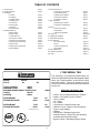
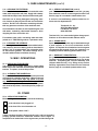
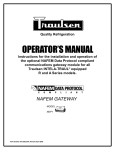
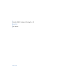
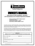
Traulsen & Co., Inc.
Quality Refrigeration
OWNER’S MANUAL
Instructions for the installation, operation,
and maintenance of all VPS* Pizza Prep Table Models:
*U.S. Patent No. 6,089,036
VPS48S
VPS54S
VPS66S
VPS72S
VPS90S
VPS114S
This Traulsen unit is built to our highest quality standards. We build our refrigerators, freezers and heated
cabinets this way as a matter of pride. This philosophy has made Traulsen the leader in commercial refrigeration since 1938. We thank you for your choice and confidence in Traulsen equipment and we know you
will receive many years of utility from this equipment.
All Traulsen units are placed on a permanent record file with the service department. In the event of any
future questions you may have, please refer to the model and serial number found on the name tag affixed
to the unit. Should you need service, however, call us on our toll free number, 800-825-8220 between 7:30
a.m. and 4:30 p.m. CST, Monday thru Friday. It is our pleasure to help and assist you in every possible way.
INSTALLER
COMPLETE THE FOLLOWING INFORMATION PRIOR TO UNIT INSTALLATION
INITIAL START DATE:
SERIAL NO.
MODEL TYPE:
COMPANY/INDIVIDUAL NAME:
INSTALLER:
VPS DOC REV. 7/02
P/N 375-60178-00
TABLE OF CONTENTS
I. The Serial Tag
II. Receipt Inspection
III. Installation
a-Location
b-Packaging
c-Installing Casters
d-Installing Legs
e-Cord & Plug
f-Power Supply
g-Clearance
h-Wiring Diagram
IV. Operation/Start-Up
a-Master Switch
b-Power Supply
c-Condensing Unit
d-Turning The Unit ON
e-Checking The Temperature
f-Optional LCD Thermometer
g-Defrost Timer
h-Adjusting The Temperature
i-Error Messages
Page 1
Page 2
V. Care & Maintenance
a-Cleaning The Condenser
b-Hinge Replacement
c-Replacing The Gaskets
d-Cleaning The Exterior
e-Cleaning The Interior
VI. Misc. Operations
a-Replacing The Shelves
b-Cleaning The Raised Rail
VII. Other
a-Service Information
b-Spare Parts
c-Warranty Registration
VIII. Parts List
IX. Operational Guidelines
X. Trouble Shooting Guide
XI. Pan Capacities
a-The VPS System
b-Pans
c-Interior Arrangements
d-Lift-Up Rail
XII. Plan & Elevations
XIII. Warranty Information
XIV. Index
Page 2
Page 2
Page 2
Page 2
Page 2
Page 2
Page 2
Page 2
Page 3
Page 3
Page 3
Page 3
Page 3
Page 3
Page 3
Page 3/4
Page 4
Page 4
Page 4
Page 4
Page 5
Page 5
Page 5
Page 5
Page 5
Page 5
Page 5
Page 6/7/8
Page 8
Page 9
Page 10
Page 10
Page 10
Page 10
Page 11/12
Page 13
Page 14
I. THE SERIAL TAG
The serial tag is a permanently affixed sticker on
which is recorded vital electrical and refrigeration data
about your Traulsen product, as well as the model
and serial number. This tag is located on the left
interior wall of the compressor compartment, behind
the louvers.
FORT WORTH, TX.
SERIAL
VOLTS
MODEL
Hz
PH
TOTAL CURRENT
AMPS
MINIMUM CIRCUIT
AMPS
MAXIMUM OVERCURRENT PROTECTION
LIGHTS
WATTS
HEATERS
AMPS
AMPS
REFRIGERANT
DESIGN PRESSURE
TYPE
HIGH
OZ
LOW
REFRIGERANT
DESIGN PRESSURE
TYPE
HIGH
OZ
LOW
370-60294-00 REV (A)
NSF
®
C
UL
®
US
LISTED
-1-
READING THE SERIAL TAG
• Serial = The permanent ID# of your Traulsen
• Model = The model # of your Traulsen
• Volts = Voltage
• Hz = Cycle
• PH = Phase
• Total Current = Maximum amp draw
• Minimum Circuit = Minimum circuit ampacity
• Lights = Light wattage
• Heaters
• Refrigerant = Refrigerant type used
• Design Pressure = High & low side operating
pressures and refrigerant charge
• Agency Labels = Designates agency listings
II. RECEIPT INSPECTION
III. INSTALLATION (continued)
All Traulsen products are factory tested for performance and are free from defects when shipped. The
utmost care has been taken in crating this product to
protect against damage in transit. All legs or casters
are boxed inside to prevent damage.
III. c - INSTALLING CASTERS (cont’d):
or compartment, for proper support. See drawing on
page 6 for correct placement.
III. d - INSTALLING LEGS:
Optional legs are installed in the same manner as casters (see figure 1). When the unit is set in its
finalposition it is important for proper operation that
the unit be leveled. The legs are adjustable for this
purpose.
You should carefully inspect your Traulsen unit for
damage during delivery. If damage is detected, you
should save all the crating materials and make note
on the carrier’s Bill Of Lading describing this. A freight
claim should be filed immediately. If damage is subsequently noted during or immediately after installation, contact the respective carrier and file a freight
claim. Under no condition may a damaged unit be returned to Traulsen & Co. without first obtaining written permission (return authorization).
Please note that Traulsen units are not designed to be
moved while on legs. If the unit requires moving, a
pallet jack or forklift should be used to prevent damage.
III. INSTALLATION
Fig. 1
III. a - LOCATION:
Select a proper location for your Traulsen unit, away
from extreme heat or cold. Allow enough clearance
between the unit and the side wall so that the door (s)
may open a minimum of 90°.
III. e - CORD & PLUG:
All self-contained models are supplied with a cord &
plug attached. It is shipped coiled at the bottom of the
cabinet, secured by a nylon strip. For your safety and
protection, all units supplied with a cord and plug include a special three-prong grounding plug on the service cord. Select only a certified electrical outlet with
grounding plug for power source. NOTE: Do not under any circumstances, cut or remove the round
grounding prong from the plug, or use an extension
cord.
III. b - PACKAGING:
All Traulsen VPS units are shipped from the factory
on a sturdy wooden pallet and packaged in a durable
crate with staples. These should first be removed to
avoid scratching the unit when lifting off the crate.
Avoid laying the unit on its front, side or back for removal of the pallet.
NOTE: Traulsen does not recommend laying the unit
down on its front, side or back. However, if you must
please be certain to allow the unit to remain in an upright position afterwards for 24 hours before plugging
it in so that the compressor oils and refrigerant may
settle.
III. f - POWER SUPPLY:
It is recommended that the supply voltage be checked
prior to connection to be certain that proper voltage
for the cabinet wiring is available (refer to the serial
tag to determine correct unit voltage). Make connections in accordance with local electrical codes. Use
qualified electricians.
III. c - INSTALLING CASTERS:
Six (6) 8” high casters are supplied standard for all
VPS units. These are shipped from the factory packed
inside a cardboard box, contained within the unit.
Use of a separate, dedicated circuit is required. Size
wiring to handle indicated load and provide necessary
overcurrent protector in circuit.
WARNING: THE CABINET MUST BE BLOCKED AND
STABLE BEFORE INSTALLING LEGS OR CASTERS.
III. g - CLEARANCE:
It is important for the proper operation and longevity
of your Traulsen unit that it have adequate provisions
for air supply to the compressor. Do not store materials within 31” of the condensing unit louvers. Inadequate air flow circulation and heating will result if the
air flow is obstructed.
To install the legs or casters, first raise and block the
unit a minimum of 9” from the floor. The casters slide
into the two leg channels on the front and back of the
cabinet. These are fully adjustable along the unit’s
entire length to allow for avoiding floor obstructions,
such as drains and outlet boxes. Be certain that all
casters are tightly secured; to do this, tighten the two
bolts located at the base of each caster assembly.
III. h - WIRING DIAGRAM:
Refer to the wiring diagram for any service work performed on the unit. Should you require one, please
contact Traulsen Service at (800) 825-8220, and provide the model and serial number of the unit involved.
NOTE: Casters or legs must be installed towards the
four corners of the unit, as well under the compress-2-
IV. OPERATION/START-UP
IV. a - MASTER SWITCH:
The master switch is located at main electrical box
behind the louver panel and should be in the OFF position.
IV. h - ADJUSTING THE TEMPERATURE (cont’d):
the bottom (see figure 2). To disable the keypad, slide
the switch to left (LOCK) position. To enable the keypad, slide the switch to the right (UNLOCK) position.
Please note that the control is shipped from the factory in the locked position.
IV. b - POWER SUPPLY:
Connect the power supply cord to the proper fused
receptacle in accordance with state and local codes.
IV. c - CONDENSING UNIT:
The condensing unit is cycled by a low pressure control set at approximately 52 lbs. cut-in, 18 lbs. cut-out.
LOCKOUT: LOCK
All valves on the condensing unit are open when
shipped. Check all connections for leaks with an electronic detector before starting unit.
R
IV. d - TURNING THE UNIT ON:
Turn the master switch to the ON position.
UNLOCK
DISPLAY CODES
F
FAHRENHEIT
C
CELCIUS
H1
HEAT SATGE 1
C1
COOL STAGE 1
EP
PROBE FAILURE/
OUT OF RANGE
EE
EEPROM ERROR
E1
IMPROPER SET
E2
MEMORY ERROR
Fig. 2
IV. e - CHECKING THE TEMPERATURE:
Check the temperature of the refrigerated unit to insure cooling is being obtained, and adjust the temp
control as needed. Re-check operation after several
hours and again after two or three days.
Once the control is set to the UNLOCK position, it can
then be programmed in four simple steps using the
LCD display and the three keys on the control face.
STEP 1- To start programming, press the SET key once
to access the Fahrenheit/Celsius mode. The display
will show the current status, either F for degrees Fahrenheit or C for degrees Celsius. Press the up or down
arrow keys to toggle between the F and C designation.
IV. f - OPTIONAL LCD THERMOMETER:
If supplied with an optional LCD thermometer, to activate remove paper film from LCD thermometer battery contacts by opening the louver panel and reaching behind the thermometer to access batteries (AA
batteries included).
STEP 2- Press the SET key again to access the setpoint.
The LCD will display the current setpoint and the S1
annunciator will be blinking on and off to indicate that
the control is in the setpoint mode. Press the up and
down arrow keys to increase or decrease the setpoint
to the desired temperature.
IV. g - DEFROST TIMER:
Set defrost timer to correct time of day after unit is
plugged in. Pins are set from the factory, EXAMPLE:
10am, 2pm, 8pm, 2am and 6am. A minimum of five (5)
defrost cycles are required per day.
STEP 3- Press the SET key again to access the differential. The LCD will display the current setpoint and
the DIF1 annunciator will be blinking on and off to indicate that the control is in the differential mode. Press
the up and down arrow keys to increase or decrease
the differential to the desired setting.
IV. h - ADJUSTING THE TEMPERATURE:
The refrigeration system has been properly charged
and tested at the factory. It is regulated by an electronic control.
All control settings are retained in a non-volatile
memory. If the power supply is interrupted for any
reason, re-programming is not necessary unless different control settings are required.
STEP 4- Press the SET key to access the cooling or
heating mode. The LCD will display the current mode,
either C1 for cooling or H1 for heating. Press the up
and down arrow keys to toggle between the C1 or H1
designation. Press the SET key once more and programming is complete.
The control is equipped with a lock-out switch to prevent unauthorized tampering. When placed in the LOCK
position, the keypad is disabled and no changes to
the settings can be made. When placed in the UNLOCK position, the keypad will function normally.
NOTE: The control will automatically end programming
if no keys are depressed for a period of thirty seconds.
Any settings that have been input to the control will
be accepted at that point.
To access the lock-out switch, first disconnect the
power supply, then open the control. The switch is
located on the inside cover about two inches above
-3-
IV. OPERATION (continued)
V. CARE & MAINTENANCE
IV. h - ADJUSTING THE TEMPERATURE (cont’d):
The proper control settings for the VPS models are:
STEP ANNUNCIATOR
DESCRIPTION
1
F or C
Fahrenheit or Celsius Scale
2
S1 (blinking)
Setpoint Temperature
3
DIF1 (blinking)
Differential Temperature
4
C1/H1
Cooling or Heating Mode
V. a - CLEANING THE CONDENSER:
The most important thing you can do to insure a long,
reliable service life for your Traulsen is to regularly clean
the condenser coil.
DISPLAY
The condensing unit requires regularly scheduled cleaning to keep the finned condenser clean of lint and dust
accumulation. The frequency of cleaning will depend
on jobsite conditions; however, at least once a month
is strongly recommended. Keeping the condenser clean
allows the cabinet to operate more efficiently and use
less energy.
35
3
To clean the condenser, first disconnect electrical power
to the cabinet and remove the front louver assembly.
To remove this, lift the louver assembly out of the lower
cradle and then slide it down away from this out of the
top bracket. Vacuum or brush any dirt, lint or dust from
the finned condenser coil, the compressor and other
cooling system parts. If significant dirt is clogging the
condenser fins, use compressed air to blow this clear.
IV. i - ERROR MESSAGES:
In the event of an error message, please refer below for
troubleshooting:
E1- Appears when either the UP or DOWN arrow keys
are pressed when not in programming mode. To correct, allow the control to reset in 30 seconds. If an E1
message appears when no keys are being depressed,
contact an authorized service agent to replace the control.
After cleaning replace the louver assembly.
V. b - HINGE REPLACEMENT:
Both the door and hinge can be easily removed from
the cabinet. To remove the door, remove the screw at
the bottom of the upper hinge. To remove the door half
of the hinge from the door, slide hinge cover off and
then remove the three Phillips head screws which secure the hinge in place on the door.
E2- Appears if the control settings are not properly
stored in memory. To correct, check all settings and
correct if necessary (see section IV. a).
EP- Appears when the probe is open, shorted or sensing a temperature that is out of range. To correct, first
verify if the temperature is truly out of range, if so correct this setting. If not, contact an authorized service
agent for repair or replacement.
To remove the cabinet half of the hinge, remove the three
Phillips head screws which hold it in place.
EE- Appears if the EEPROM has been corrupted. Contact an authorized service agent to replace the control.
To reassemble the hinge reverse the previous procedure.
CL- Appears if calibration mode has been entered. To
correct, shut off the power supply to the unit for at least
five seconds. If after doing so the CL message still
apppears, contact an authorized service agent to replace
the control.
V. c - REPLACING THE GASKETS:
Before attempting to install a new gasket, both the unit
and the gasket itself must be at room temperature. To
replace a gasket, first lift-up the gasket to expose the
door liner mounting screws. Remove the Phillips head
screws which secure the interior door liner. Next, remove the door liner, and the gasket to be replaced. Then,
align the new gasket with the door and replace the door
liner. Insert the Phillips head screws into the door liner
holes and tighten to secure both the gasket and door
liner to the door.
WARNING: DISCONNECT ELECTRICAL POWER
SUPPLY BEFORE CLEANING ANY PARTS OF THE
UNIT.
-4-
V. CARE & MAINTENANCE (cont’d)
V. d - CLEANING THE EXTERIOR:
Exterior stainless steel should be cleaned with warm
water, mild soap and a soft cloth. Apply with a dampened cloth and wipe in the direction of the metal grain.
VII. a - SERVICE INFORMATION (cont’d):
your Traulsen unit. If you cannot locate this, you may
also obtain the name of a service agent from the Tech
Service page of our website: www.traulsen.com.
Avoid the use of strong detergents and gritty, abrasive cleaners as they may tend to mar and scratch the
surface. Do NOT use cleansers containing chlorine,
this may promote corrosion of the stainless steel.
If service is not satisfactory, please contact our inhouse service department at:
Traulsen & Co., Inc.
4401 Blue Mound Road
Fort Worth, TX 76106
(800) 825-8220
Care should also be taken to avoid splashing the unit
with water, containing chlorinated cleansers, when
mopping the floor around the unit.
Traulsen & Co., Inc. reserves the right to change specifications or discontinue models without notice.
For stubborn odor spills, use baking soda and water
(mixed to a 1 TBSP baking soda to 1 pint water ratio).
VII. b - SPARE PARTS:
Spare or replacement parts may be obtained through
a parts supplier or one of our authorized service
agents. A complete list of authorized service agents
accompanies this manual and is also posted on our
company’s official website @ www.traulsen.com.
V. e - CLEANING THE INTERIOR:
For cleaning both stainless steel and anodized aluminum interiors, the use of baking soda as described in
section “V. d” is recommended. Use on breaker strips
as well as door gaskets. All interior fittings are removable without tools to facilitate cleaning.
VII. c - WARRANTY REGISTRATION:
For your convenience, the warranties on your new
Traulsen unit may be registered with us by one of two
methods. Completing the enclosed warranty card
(shipped with the unit), or by filling out the on-line
warranty registration form located on the Technical
Service page of our website (www.traulsen.com).
VI. MISC. OPERATIONS
VI. a - REPLACING THE SHELVES:
The shelves can be readily removed by simply lifting
them clear of the side wall mounted pins and mullion
bracket. To replace, reverse the process.
VI. b - CLEANING THE RAISED RAIL:
To clean the rail area, first remove all food pans and
rail inserts (for cleaning separately). Wipe out the rail
area being careful not to wipe any debris on or into
any of the raised openings in the rail bottom. These
are air discharge and air returns for the VPS system,
and must be kept clean, clear and open for proper operation.
VII. OTHER
VII. a - SERVICE INFORMATION:
Before calling for service, please check the following:
Is the electrical cord plugged in?
Is the fuse OK or circuit breaker on?
Is the power switch “ON”?
If after checking the above items and the unit is still not operating
properly, please contact an authorized Traulsen service agent. A
complete list of authorized service agents was provided along with
-5-
VIII. PARTS LIST
VPS48S & VPS54S
KEY
DESCRIPTION
PART NUMBER
1
2
3
4
5
6
7
8
9
10
11
12
13
14
15
16
17
18
19
20
21
LOUVER
8” CASTER ASS’Y W/O BRAKES
8” CASTER ASS’Y W/BRAKES
DOOR HANDLE
LCD THERMOMETER (OPTIONAL)
CORD & PLUG (NOT SHOWN)
RH DOOR ASS’Y (INCLUDING GASKET & HARDWARE)
LH DOOR ASS’Y (INCLUDING GASKET & HARDWARE)
DOOR GASKET (16-1/8” x 22-1/8”)
DOOR HINGE
DOOR HINGE SPRING KIT
AIR DEFLECTOR
AIR DIFFUSER ASS’Y
40 WATT COATED BULB (OPTIONAL)
LAMP SOCKET (OPTIONAL)
BLOWER COIL (EVAPORATOR)
CLEAR DRAIN TUBE
PLASTIC SHELF SUPPORT
WIRE SHELF
LIFT LID BRACKET
LIFT LID
6132004
409-010-310-000
409-010-311-000
6051000
403-130-079-600
401-130-079-600
VPS-18R
VPS-18L
418-130-105-200
409-130-056-200
409-130-056-300
133-202
133-203
401-130-079-700
409-010-019-000
403-009-766-000
944075
409-009-515-000
410-130-104-900
6005018RH, 6005019LH
056-903 (VPS54S only)
-6-
VIII. PARTS LIST (CONTINUED)
VPS66S, VPS72S, VPS90S & VPS114S
KEY
DESCRIPTION
PART NUMBER
1
2
3
4
5
6
7
8
9
10
11
12
13
14
15
16
17
18
LOUVER
LOUVER (VPS72S)
8” CASTER ASS’Y W/O BRAKES
8” CASTER ASS’Y W/BRAKES
DOOR HANDLE
LCD THERMOMETER (OPTIONAL)
CORD & PLUG (NOT SHOWN)
DOOR GASKET (22-1/8” x 22-1/8”)
DOOR HINGE
DOOR HINGE SPRING KIT
LIFT LID (VPS66S)
LIFT LID (VPS72S)
LIFT LID (VPS90S)
LIFT LID (VPS114S)
LIFT LID SPACER
LH DOOR ASS’Y (INCLUDING GASKET & HARDWARE)
RH DOOR ASS’Y (INCLUDING GASKET & HARDWARE)
AIR DEFLECTOR (VPS66S)
AIR DEFLECTOR (VPS72S)
AIR DEFLECTOR (VPS90S)
AIR DEFLECTOR (VPS114S)
AIR DIFFUSER (VPS66S)
AIR DIFFUSER (VPS72S)
AIR DIFFUSER (VPS90S)
AIR DIFFUSER (VPS114S)
40 WATT COATED BULB (OPTIONAL)
LAMP SOCKET (OPTIONAL)
BLOWER COIL (EVAPORATOR FOR VPS66,72 & 114S)
BLOWER COIL (EVAPORATOR FOR VPS90S)
CLEAR DRAIN TUBE
PLASTIC SHELF SUPPORT
WIRE SHELF
LIFT LID BRACKET
6132004
6132005
409-010-310-000
409-010-311-000
6051000
403-130-079-600
401-010-304-000
418-130-105-300
409-130-056-200
409-130-056-300
056-246
056-288
056-266
056-210
056-209
VPS-24L
VPS-24R
056-260
056-297
056-280
056-237
056-100
265-204
243-100
056-600
401-130-079-700
409-010-019-000
403-130-084-300
403-009-766-000
944075
409-009-515-000
410-130-104-800
6005018RH, 6005019LH
19
20
21
22
23
24
25
26
-7-
IX. OPERATIONAL GUIDELINES
Please follow these simple guidelines for proper VPS operation:
•
The defrost timer must be set to the proper time of day. If the unit is shut
down at any time, the clock must be reset.
•
Rail inserts must be in place (under pans) before loading any pans.
•
For best results in holding product temperatures, stainless steel pans should
be used in the rail, rather than plastic pans.
•
The rail area must have a full complement of pans in place at all times. This
is true even when the unit is not in use with the lid closed, but operational,
especially overnight.
•
These units have been designed to operate in an ambient room environment of 86°F (30°C) or less.
•
Do not allow air drafts (such as heat or A/C ceiling registers) to blow on, or
over, the rail area. This will disrupt the air blanket over the product area,
resulting in uneven to poor holding temperatures.
•
Rail covers should be closed over the rail whenever slow times of operations allow.
•
Product should be loaded into the rail at a minimum temperature of
35° to 36°F. The VPS unit was not designed to pull down product
temperature, but rather to maintain it.
•
Do not allow blockage of blower fans located in lower base storage
area, such as by stacking boxes, etc. under fans or allowing materials such
as plastic wrap to be sucked into the fan guards.
•
Do not block open base refrigerator doors open while loading or unloading.
•
When cleaning the rail area, do not wipe any debris on or into the any of the
raised openings in the rail bottom. These are air discharge and air returns
for the VPS system, and must be kept clean, clear and open.
-8-
X. TROUBLE SHOOTING GUIDE
FIND YOUR PROBLEM HERE
REMEDY
1.Condensing unit fails to start.
a.
b.
c.
Check if line has been disconnected.
Check T-Stat setting and operation.
Check switch behind louvers.
2. Condensing unit operates for
prolonged periods or continuously.
a.
Shortage of refrigerant, locate and repair
leak, evacuate and recharge per the
manufacturer’s requirements.
Dirty condenser or filter. Clean properly.
Are doors closing properly?
Evaporator coil iced. Check defrost clock and
heating element.
Check to see if there are any restrictions in
refrigeration system.
b.
c.
d.
e.
3. Food compartment is too warm.
a.
Thermostat setting too high, readjust
thermostat.
Perhaps a large quantity of food has
recently been added or the door was kept
open for a long period of time, in both
cases, allow adequate time for the cabinet
to recover its normal operating temperature.
Check door gasket for proper seal.
b.
c.
4. Food compartment is too cold.
a.
Adjust the thermostat to a warmer
setting.
5. Condensation on the exterior surface.
a.
Condensation on the exterior surface of the
unit is perfectly normal during periods of
high humidity.
Check door alignment and gaskets for
proper seal.
b.
-9-
XI. PAN CAPACITIES
XI. a - THE VPS SYSTEM:
The Venturi Plenum System (VPS) pizza prep tables
are designed to keep all foods fresh, at an even temperature, without freezing. The VPS system accomplishes this task by surrounding product with cold air,
top to bottom, and on all sides without drying the ingredients. This extends shelf life, eliminating the need to
stir products or rotate pans. It has the added benefit of
eliminating clean-up associated with the frost build-up
and condensation found in “wrapped rail” designs. The
standard 12" front to back raised rail places pans in full
view, where they are both easy to use, and can be
completely filled, further reducing labor required to
operate.
Third Size Pan Capacity
Std. Rail Models (w/o adapter bars)
Full Size Pan Capacity
(w/o adapter bars)
VPS48S
6
2
VPS54S
7
2-1/3
VPS66S
9
3
VPS72S
10
3-1/3
VPS90S
12
4
VPS114S
16
5-1/3
XI. b - PANS:
The VPS models are all designed to accommodate either full size (12” x 20”), half or third size pans without
the use of adapter bars (pans supplied by others). See
chart top right for pan capacities.
XI. c - INTERIOR ARRANGEMENTS:
One (1) powder coated shelf is mounted behind each
door. Optional angle type or chrome rod type tray slides
may be ordered in place of these, however please note
that tray slides are not available for either 48” or 54”
long models.
XI. d - RAIL COVER:
Each VPS Prep Table includes a stainless steel lift-up
rail cover, which can be set in either the 45° or fully
opened position. Opened at 45°, the rail cover extends
to a height of 12-1/2” (31.75 cm) above the unit.
Opened at 90°, the rail cover extends to a height of 161/2” (41.91 cm) above the unit.
-10-
XI. PLAN & ELEVATIONS
VPS48S
VPS54S
VPS66S
-11-
XI. PLAN & ELEVATIONS (cont’d)
VPS72S
VPS90S
VPS114S
(drawings not to scale with those of other models)
-12-
XIII. WARRANTY INFORMATION
STANDARD DOMESTIC WARRANTY
TRAULSEN & CO., INC. warrants new equipment to the original purchaser, when installed within the United States against
defective material and workmanship for one (1) year from the date of original installation, not to exceed 15 months from
date of shipment. Under this warranty, TRAULSEN & CO., INC. will repair or replace, at its option, including service and
labor, all parts found to be defective and subject to this warranty. The compressor part is warranted for an additional
four (4) years. During this period TRAULSEN & CO., INC. will supply replacement compressor(s) if deemed defective,
however, all installation, recharging and repair costs will remain the responsibility of the owner.
This warranty does not apply to damage resulting from fire, water, burglary, accident, abuse, misuse, transit, acts of
God, terrorism, attempted repairs, improper installation by unauthorized persons, and will not apply to food loss.
THERE ARE NO ORAL, STATUTORY OR IMPLIED WARRANTIES APPLICABLE TO TRAULSEN, INCLUDING BUT NOT LIMITED TO, ANY IMPLIED WARRANTY OF MERCHANTABILITY OR FITNESS FOR ANY PARTICULAR PURPOSE WHICH EXTEND BEYOND THE DESCRIPTION ON THE FACE HEREOF. TRAULSEN SHALL HAVE NO OBLIGATION OR LIABILITY FOR
CONSEQUENTIAL OR SPECIAL DAMAGES, GROWING OUT OF OR WITH RESPECT TO THE EQUIPMENT OR ITS SALE,
OPERATION OR USE, AND TRAULSEN NEITHER ASSUMES NOR AUTHORIZES ANYONE ELSE TO ASSUME FOR IT ANY
OBLIGATION OR LIABILITY IN CONNECTION WITH THE EQUIPMENT OR ITS SALE, OPERATION OR USE OTHER THAN
AS STATED HEREIN.
INTERNATIONAL COMMERCIAL WARRANTY
(for Canadian warranties see domestic US warranty)
TRAULSEN & CO., INC. warrants to the original purchaser the Refrigeration Equipment manufactured and sold by it to be free
from defects in material and workmanship under normal use and service for a period of one (1) year from date of shipment. Under
this warranty, TRAULSEN & CO., INC. will reimburse the purchaser for the replacement of any part of said equipment (excluding
dryers & refrigerant gas) which then proves to be defective. This warranty does not apply to damage resulting from fire,
water, burglary, accident, abuse, misuse, transit, acts of God, terrorism, attempted repairs, improper installation by
unauthorized persons, and will not apply to food loss.
TRAULSEN’S standard warranty does not apply to Export Sales. Rather, for a period of one (1) year from date of original
installation not to exceed Fifteen (15) months from date of shipment from factory, TRAULSEN:
will replace, F.O.B. factory, any defective parts normally subject to warranty.
will not cover the cost of packing, freight or labor such costs being the sole responsibility of the dealer.
THIS WARRANTY IS IN LIEU OF ALL OTHER WARRANTIES EITHER EXPRESSED OR IMPLIED AND CONSTITUTES
TRAULSEN’S FULL OBLIGATION AND LIABILITY. WARRANTIES NOT AVAILABLE ON REMOTE MODELS.
-13-
XIV. INDEX
A
Adapter Bars
Adjusting The Temperature
N
11
3, 4
O
B
C
Calibration - Mode
Casters
Celsius
Cleaning - The Condenser
Cleaning - The Exterior
Cleaning - The Interior
Clearance
Compressor - Oil
Condensing Unit
Control - Electronic
Cord & Plug
4
2
3, 4
4
5
5
2
2
3, 4
3
2
D
Damage - Freight
Differential - Setting
Door Liner
2
3
4
E
Error - Message
4
F
Fans
Fahrenheit
Freight Claim
9
3, 4
2
G
Gaskets
4, 5
H
Hinge - Replacement
4
P
Pallet - Shipping
Pans
Power Supply
2
11
2
R
Rail Inserts
Rail - Refrigerated
Refrigerant
Return Authorization
9
5
2
2
S
Serial Tag
Setpoint - Setting
Shelves
Standard (12” Front to Back) Rail
1
3
5
11
T
Temperature - Adjustment
Thermometer - LCD
3, 4
3
U
V
Venturi Plenum System (VPS)
11
W
Warranty
Warranty, Registration
Wiring Diagram
13
5
2
X
Y
I
Z
J
K
L
Legs
Leg Channels
Louver Panel
2
2
1, 3, 4
M
Master Switch
3
-14-
HOURS OF OPERATION:
Monday thru Friday 7:30 a.m. - 4:30 p.m. CST
EXTENDED WARRANTY SERVICE HOURS
Monday thru Friday 4:30 p.m. - 6:00 p.m. CST
Traulsen & Co., Inc.
4401 Blue Mound Road Fort Worth, TX 76106
Phone: (800) 825-8220 Fax-Svce: (817) 740-6757
Website: www.traulsen.com
Quality Refrigeration