1
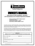
Quality Refrigeration
OWNER’S MANUAL
Instructions for the installation, operation
and maintenance of Traulsen:
RMC Milk Cooler
RMC34, RMC49 & RMC58 Models
This Traulsen unit is built to our highest quality standards. We build our refrigerators and freezers this way as a matter of pride.
This philosophy has made Traulsen the leader in commercial refrigeration since 1938. We thank you for your choice and confidence in Traulsen equipment and we know you will receive many years of utility from this equipment.
All Traulsen units are placed on a permanent record file with the service department. In the event of any future questions you
may have, please refer to the model and serial number found on the name tag affixed to the unit. Should you need service, call
us on our toll free number, 800-825-8220 between 7:30 am - 4:30 pm CST, Monday thru Friday. You may also log onto www.
traulsen.com for further information. It is our pleasure to help and assist you in every possible way.
INSTALLER
COMPLETE THE FOLLOWING INFORMATION PRIOR TO UNIT INSTALLATION
INITIAL START DATE:SERIAL NO.
MODEL TYPE:
COMPANY/INDIVIDUAL NAME:
INSTALLER: FORM NUMBER TR35944 (REV. 02-04-14) P/N 375-60324-00
TABLE OF CONTENTS
I. THE SERIAL TAG
Page 1
II. RECEIPT INSPECTION
Page 2
III. INSTALLATION
a-LocationPage 2
b-PackagingPage 2
c-Installing/Adjusting the Casters Page 2
d-Cord & PlugPage 2
e-Power SupplyPage 2
IV. OPERATION
a-Temperature ControlPage 2
V. CARE & MAINTENANCE
a-Cleaning The Condenser/Filter
Page 3
b-Replacing The Door Gaskets
Page 3
c-Cleaning The Cabinet Surface
Page 3
VI. WIRING DIAGRAM
Page 4
VII. TROUBLE SHOOTING GUIDE
Page 5
VIII. SERVICE ASSISTANCE
a-Service Check List
Page 5
b-Service InformationPage 5
IX. WARRANTIESPage 6
X. SERVICE PARTS LIST
Page 7-8
I. THE SERIAL TAG
The serial tag is a permanently affixed label on which is
recorded vital electrical and refrigeration data about your
Traulsen product, as well as the model and serial number.
This tag is located in the left interior compartment on all
standard milk cooler models.
FORT WORTH, TX.
SERIAL VOLTS MODEL
Hz TOTAL CURRENT
AMPS
MINIMUM CIRCUIT
AMPS
MAXIMUM OVERCURRENT PROTECTION
LIGHTS
WATTS
HEATERS
AMPS
PH
READING THE SERIAL TAG
AMPS
REFRIGERANT
DESIGN PRESSURE
TYPE
HIGH
OZ
LOW
REFRIGERANT
DESIGN PRESSURE
TYPE
HIGH
OZ
LOW
370-60294-00 REV (A)
-1-
• Serial = The permanent ID# of your Traulsen unit
• Model = The model # of your Traulsen unit
• Volts = Voltage
• Hz = Cycle
• PH = Phase
• Total Current = Maximum amp draw
• Minimum Circuit = Minimum circuit ampacity
• Lights = Light wattage
• Heaters = Heater amperage (Hot Food units only)
• Refrigerant = Refrigerant type used
• Design Pressure = High & low side operating
pressures and refrigerant charge
• Agency Labels = Designates agency listings
II. RECEIPT INSPECTION
III. INSTALLATION (continued)
All Traulsen products are factory tested for performance
and are free from defects when shipped. The utmost care
has been taken in crating this product to protect against
damage in transit.
III. c - INSTALLING/ADJUSTING LEGS OR CASTERS:
You should carefully inspect your unit for damage during
delivery. If damage is detected, you should save all the
crating materials and make note on the carrier’s Bill Of
Lading describing the damage. A freight claim should be
filed immediately. If damage is subsequently noted during or immediately after installation, contact our customer
care team to file a freight claim. There is a fifteen (15)
day limit to file freight damage with the carrier. Under no
condition may a damaged unit be returned to Traulsen
without first obtaining written permission (return authorization). You may contact Hobart/Traulsen customer
care at 800-333-7447 to request a return or file a claim.
III. INSTALLATION
III. a - LOCATION:
Select a proper location for your unit, away from extreme
heat or cold.
III. b - PACKAGING:
Your Traulsen unit is shipped from the factory bolted to a
sturdy wooden pallet in stretch wrapped material.
III. d - CORD & PLUG:
All self-contained models are shipped standard with a NEMA
5-15P plug and 9 foot cord . Select only a dedicated electrical
outlet for power source.
NOTE: Do not under any circumstances, cut or remove the
round grounding prong from the plug, or use an extension
cord.
III. e - POWER SUPPLY:
The supply voltage should be checked prior to connection to
be certain that proper voltage for the cabinet wiring is available
(refer to the serial tag to determine correct unit voltage, see page
1). Make connections in accordance with local electrical codes.
Use qualified electricians.
Most exterior stainless steel surfaces have a protective
vinyl covering to prevent scratching during manufacturing, shipping and installation. After the unit is installed
in place of application peel, remove and discard the
covering from all surfaces.
Use of a separate, dedicated circuit is required. Size wiring to
handle indicated load and provide necessary over current protector in circuit (see amperage requirements on the unit’s serial tag).
To remove the wooden pallet, first if at all possible, we
suggest that the cabinet remain bolted to the pallet during all transportation to the point of final installation. The
bolts can then be removed with a 1/2” socket wrench.
Avoid laying the unit on its back for removal of the pallet.
IV. a - TEMPERATURE CONTROL:
IV. OPERATION
The temperature is set at the factory but local conditions may
necessitate slight adjustment.
NOTE: Traulsen does not recommend laying the unit
on its back. If you must, please allow the unit to remain in an upright position for 24 hours before plugging it in so that the compressor oils and refrigerant
may settle.
III. c - INSTALLING/ADJUSTING LEGS OR
CASTERS:
Casters are installed at the factory but will require adjustment upon installation.
To adjust the legs or casters, loosen the two bolts and
move leg or caster to desired location, spacing between
leg or caster not to exceed 48 inches. Leg or caster on
each end of the unit can not exceed 8 inches from the
end of the cabinet.
The temperature control is located behind the silver plug on the
front side of the system area (dial thermometer side). To adjust,
remove the plug turn the adjustment screw with a pair of pliers
a small amount at a time; turning clockwise lowers the temperature. An “OFF” position is fully counterclockwise and interrupts
power to the compressor and condenser fan only, not the entire
refrigerator.
-2-
IV. OPERATION (continued)
V. CARE & MAINTENANCE (continued)
IV. a - TEMPERATURE CONTROL: (continued)
F
V. b - REPLACING THE DOOR GASKETS:
Colder
R
Top Door
Gasket
O
N
T
Temperature
Adjustment
Shaft
V. CARE & MAINTENANCE
V. c - CLEANING THE CABINET SURFACES:
V. a - CLEANING THE CONDENSER/FILTER:
The most important thing you can do to insure a long, reliable
service life for your Traulsen is to regularly clean the condenser
coil and or filter.
WARNING: DISCONNECT ELECTRICAL POWER SUPPLY
BEFORE CLEANING ANY PARTS OF THE UNIT.
To clean the condenser/filter, first disconnect electrical power to
the cabinet and remove the system side cover.
Proceed to vacuum or brush any dirt, lint or dust from the finned
condenser coil/filter, the compressor and other cooling system
parts. If significant dirt is clogging the condenser fins or filter,
use compressed air to blow this clear.To replace the system side
cover reverse the process.
V. b - REPLACING THE DOOR GASKETS:
To remove the gasket to be replaced, grasp it firmly by one corner
and pull it out. Before attempting to install a new gasket, both
the unit and the gasket itself must be at room temperature. Insert
the four corners first by using a rubber mallet (or hammer with
a block of wood). After the corners are properly inserted, work
your way towards the center from both ends by gently hitting
with a mallet until the gasket is completely seated in place (see
figure below for proper gasket placement).
WARNING: DISCONNECT ELECTRICAL POWER
SUPPLY BEFORE CLEANING ANY PARTS OF THE
UNIT.
Exterior stainless steel should be cleaned with warm water, mild soap and a soft cloth. Apply with a dampened
cloth and wipe in the direction of the metal grain.
Avoid the use of strong detergents and gritty, abrasive
cleaners as they may tend to mar and scratch the surface. Do NOT use cleansers containing chlorine, such as
bleach, this may promote corrosion of the stainless steel.
Care should also be taken to avoid splashing the unit with
water, containing chlorinated cleansers, when mopping
the floor around the unit.
For stubborn odor or spills, use baking soda and water
(mixed to a 1 tbsp baking soda to 1 pint water ratio).
A stainless steel polish is recommended for shining of
unit.
NOTE: The gasket may appear too large, but if it is installed
as indicated above it will slip into place.
Front Door
Gasket
The unit is equipped with a drain for cleaning the inside
of the unit.
NOTE: System gasket attached with screw.
-3-
VI. WIRING DIAGRAM
NOTE: Refer to the wiring diagram below for any service work performed by a qualified technician.
-4-
VII. TROUBLE SHOOTING GUIDE
PROBLEM
POSSIBLE SOLUTION
1. Condensing unit fails to start.
a. Check if cord & plug has been disconnected.
b. Clean Condenser
2. Condensing unit operates for prolonged
periods or continuously.
a. Are doors closed properly?
b. Dirty condenser or filter. Clean properly.
c. Evaporator coils iced. Needs to defrost.
3. Food Compartment is too warm.
a. Check door(s) and gasket(s) for proper seal.
b. Check if a large quantity of warm food was recently added or the
door was kept open for a long period of time.
c. Clean Condenser
(NOTE: Compressor may be cycling ON/OFF
frequently)
4. Food Compartment is too cold.
a. Check if a large quantity of very cold or frozen food has recently
been added. Allow adequate time for the cabinet to recover its normal operating temperature.
5. Condensation on exterior surface.
a. Check door(s) alignment and gaskets for proper seal.
b. Condensation on the exterior surface of the unit is perfectly normal during periods of high humidity.
6. Compressor hums & does not start.
a. Call for service.
VII. SERVICE ASSISTANCE
VII. a - SERVICE CHECK LIST:
Before calling for service, please check the following:
Is the electrical cord plugged in?
Is the fuse OK or circuit breaker on?
Clean condenser coil
Is the power switch on?
If after checking the above items and the unit is still not operating properly, please contact an authorized Traulsen service
agent. A complete list of authorized service agents was provided along with your Traulsen unit. If you cannot locate this,
you may also obtain the name of a service agent from the Tech Service page at traulsen.com. If service is not satisfactory,
please contact our in-house service department at:
Traulsen
4401 Blue Mound Road Fort Worth, TX 76106
800.825.8220
Traulsen reserves the right to change specifications or discontinue models without notice.
VII. b - SERVICE INFORMATION:
To purchase replacement parts or to speak to service support for Traulsen and most Hobart Refrigeration units please
contact our Ft. Worth facility by phone at 800.825.8220 or fax to 817.740.6748 (parts) or 817.740.6757 (service).
To obtain other service informaiton you may log onto:
1. traulsen.com
2. Select Service & Parts Tab (upper right of screen)
3. Select one of the following: Service Finder, Service Parts Manuals, Parts Pricing & Warranty Registration
NOTE: When calling for service support, please make sure you have model and serial number of unit available.
-5-
IX. WARRANTIES
STANDARD DOMESTIC WARRANTY
TRAULSEN warrants new equipment to the original purchaser, when installed within the United States against
defective material and workmanship for three (3) years from the date of original installation. Under this
warranty, TRAULSEN will repair or replace, at its option, including service and labor, all parts found to be
defective and subject to this warranty. Warranty term begins upon the date of Installation, the date of End User
Invoice or the date of Dealer Invoice, whichever is proven to occur latest, not to exceed 18 months from Dealer
Invoice date (the “Warranty Period”). Warranty excludes components that are removable without tools.
The compressor part is warranted for an additional t w o (2) years. During this period TRAULSEN will supply
replacement compressor(s) if deemed defective, however all installation, recharging and repair costs will remain
the responsibility of the owner.
This warranty does not apply to damage resulting from fire, water, burglary, accident, abuse, misuse, transit, acts
of God, terrorism, attempted repairs, improper installation by unauthorized persons, and does not apply to food
loss.
For Traulsen units purchased with a remote feature, standard warranty will apply only to those components
contained within the unit to the point of connection of the refrigeration lines leading to the remote condenser.
“Defective Part Return” – All claimed defective r e p l a c e m e n t part(s) must be returned to TRAULSEN for
i n s p e c t i o n within 30 days from the date of the repair. Failure to return all claimed defective part(s) to
TRAULSEN will invalidate the warranty claim, this warranty statement, and forfeit payment for those repairs
affected.
INTERNATIONAL COMMERCIAL WARRANTY
TRAULSEN warrants to the original purchaser the Refrigeration Equipment shall be manufactured free from
defects in material and workmanship under normal use and service for a period of one (1) year from date of
shipment. Under this warranty, TRAULSEN will reimburse the purchaser for the replacement of any part of said
equipment (excluding dryers & refrigerant gas) which then proves to be defective. This warranty does not
apply to damage resulting from fire, water, burglary, accident, abuse, misuse, transit, acts of God, terrorism,
attempted repairs, improper installation by unauthorized persons, and will not apply to food loss.
TRAULSEN’S standard warranty does not apply to Export Sales. Rather, for a period of one (1) year from date
of original installation not to exceed Fifteen (15) months from date of shipment from factory, TRAULSEN: will, at
Traulsen’s sole discretion, replace or repair, F.O.B. factory, any defective parts normally subject to warranty and
will not cover the cost of packing, freight or labor, such costs being the sole responsibility of the dealer.
THERE ARE NO ORAL, STATUTORY OR IMPLIED WARRANTIES APPLICABLE TO TRAULSEN, INCLUDING BUT NOT
LIMITED TO, ANY IMPLIED WARRANTY OF MERCHANTABILITY OR FITNESS FOR ANY PARTICULAR PURPOSE WHICH
EXTEND BEYOND THE DESCRIPTION ON THE FACE HEREOF. TRAULSEN SHALL HAVE NO OBLIGATION OR LIABILITY
FOR CONSEQUENTIAL OR SPECIAL DAMAGES, INCLUDING, BUT NOT LIMITED TO, INDIRECT, PUNITIVE
DAMAGES, LOSS OF USE, LOSS OF PRODUCT, DOWN TIME OR LOST PROFITS, GROWING OUT OF OR WITH
RESPECT TO THE EQUIPMENT OR ITS SALE, OPERATION OR USE, AND TRAULSEN NEITHER ASSUMES NOR
AUTHORIZES ANYONE ELSE TO ASSUME FOR IT ANY OBLIGATION OR LIABILITY IN CONNECTION WITH THE
EQUIPMENT OR ITS SALE, OPERATION OR USE OTHER THAN AS STATED HEREIN.
THIS WARRANTY IS IN LIEU OF ALL OTHER WARRANTIES EITHER EXPRESSED OR IMPLIED AND CONSTITUTES
TRAULSEN’S FULL OBLIGATION AND LIABILITY. WARRANTIES NOT AVAILABLE ON REMOTE MODELS.
-6-
X. SERVICE PARTS LIST
ITEM
DESCRIPTION
CASTER
ALL MODELS
LEG
PART NUMBER
6" ADJUSTABLE CASTER NO LOCK
SER-60538-00
6" ADJUSTABLE CASTER WITH LOCK
SER-60538-01
4" ADJUSTABLE CASTER NO LOCK
SER-60536-00
4" ADJUSTABLE CASTER WITH LOCK
SER-60536-01
ALL MODELS
6" LEG
DOOR
SER-60542-00
MODELS RMC34
TOP DOOR ASSEMBLY
200-60899-02
FRONT DOOR ASSEMBLY
200-60899-03
MODELS RMC49
TOP DOOR ASSEMBLY
200-60899-00
FRONT DOOR ASSEMBLY
200-60899-01
MODELS RMC58
FLOOR RACKS
TOP DOOR ASSEMBLY
200-60899-04
FRONT DOOR ASSEMBLY
200-60899-05
GASKET TOP DOOR RMC34
341-60267-00
GASKET TOP DOOR RMC49
341-60267-01
GASKET TOP DOOR RMC58
341-60267-02
GASKET FRONT DOOR RMC34
341-60262-00
GASKET FRONT DOOR RMC49
341-60262-01
GASKET FRONT DOOR RMC58
341-60262-02
GASKET SYSTEM RMC34
341-60268-00
GASKET SYSTEM RMC49
341-60268-01
GASKET SYSTEM RMC58
341-60268-02
DOOR CATCH
3801100
BUMPER
358-60247-00
DOOR SLIDE LH
560-10280-00
DOOR SLIDE RH
560-10280-01
PIN FRONT DOOR
SER-60620-00
HINGE
409-130-056-200
ALL MODELS
FLOOR RACK 14-3/4"
701-61633-00
MODELS RMC58
FLOOR RACK 8-3/4"
AIR DUCT
701-61634-00
MODELS RMC34
AIR DUCT ASSEMBLY
600-70050-00
MODELS RMC49 & RMC58
AIR DUCT ASSEMBLY
DRAIN
600-70050-01
ALL MODELS
STOPPER 1"
358-10077-00
-7-
X. SERVICE PARTS LIST (continued)
ITEM
DESCRIPTION
REF SYSTEM
MODELS RMC34S
PART NUMBER
REPLACEMENT REFRIGERATION SYSTEM SINGLE ACCESS
SER-60617-00
MODELS RMC34D
REPLACEMENT REFRIGERATION SYSTEM DUAL ACCESS
SER-60617-01
MODELS RMC49S
REPLACEMENT REFRIGERATION SYSTEM SINGLE ACCESS
SER-60618-00
MODELS RMC49D
REPLACEMENT REFRIGERATION SYSTEM DUAL ACCESS
SER-60618-01
MODELS RMC58S
REPLACEMENT REFRIGERATION SYSTEM SINGLE ACCESS
SER-60619-00
MODELS RMC58D
REPLACEMENT REFRIGERATION SYSTEM DUAL ACCESS
CONTROL
SER-60619-01
ALL MODELS
MICROPROCESSOR CONTROL
337-60445-00
MICROPROCESSOR COIL TEMPERATURE SENSOR
337-60447-00
MICROPROCESSOR CABINET TEMPERATURE SENSOR
337-60448-00
THERMOMETER DIAL
344-60249-00
NOTE: Part numbers listed are for standard products as currently manufactured. For products manufactured as
other than standard, please contact the factory.
-8-
HOURS OF OPERATION:
Monday thru Friday 7:30 am - 4:30 pm CST
Quality Refrigeration
Traulsen
4401 Blue Mound Road Fort Worth, TX 76106
Phone 800.825.8220 Fax 817.740.6757
traulsen.com
© 2014 Traulsen - All Rights Reserved