1
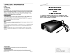
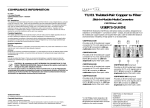
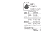
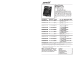
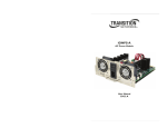
User’s Guide
CPSMP-120
AC Power Supply Module
• PointSystem™
• CPSMC13xx-100 Accessory
I
0
The Transition Networks CPSMP-120
power supply is an AC slide-in-module
that provides optional, redundant
power to the CPSMC13xx-100
PointSystem™ 13-slot chassis and any
installed media converter slide-inmodules and management modules.
The figure below illustrates the components of the CPSMP-120 power supply:
•
An On/Off switch that, when set to “I”, allows the power supply module
to supply power to the chassis, and any installed modules.
•
A panel fastener screw that secures the power supply module to the
chassis.
•
A power LED indicator.
•
A handle for installing and removing the power supply module to/from
the chassis.
•
A fuse installed in a fuse holder.
•
An external power connector that supplies power from a standard AC
wall outlet.
On/Off Switch
Panel Fastener Screw
I
0
Power LED
Handle
Fuse Holder
External Power Connector
Install the CPSMP-120 . . . . . . . . .3
Connect to External Power . . . . . .4
Replace the CPSMP-120 . . . . . . . .5
Replace the Fuse . . . . . . . . . . . . .7
Technical Specifications . . . . . . . .8
Troubleshooting . . . . . . . . . . . . . .9
Compliance Information . . . . . . .11
CPSMP-120
CAUTION: Wear a grounding device and observe electrostatic discharge
precautions when installing or servicing the power supply module. Failure to
observe this caution could result in damage to, and subsequent failure of, the
power supply module.
CPSMP-120 in the 13-Slot Chassis
The CPSMP-120 power supply module may replace an existing CPSMP-120
module or be installed in the second installation slot (see drawing below) of the
CPSMC1300-100 13-slot chassis to become the optional, redundant power
supply.
Install the CPSMP-120
CAUTION: Ensure that the power supply module has been disconnected
from the external power source and the module’s On/Off switch has been
set to “0”. Failure to observe this caution could result in damage to, and
subsequent failure of, the power supply module.
NOTE: The CPSMP-120 power supply module may be “hot swapped” (i.e.,
installed in the chassis while the chassis is in operation) provided the module
to be installed has been disconnected from its external power source and the
module’s On/Off switch has been set to “0”.
I
0
AC Power
Second
Supply Installation Slot
WARNING: Do not connect the power supply module to the external power
source before installing it into the chassis. Failure to observe this caution could
result in equipment damage and/or personal injury or death.
To install the CPSMP-120 power supply module into the CPSMC13xx-100
chassis:
1.
Loosen the screw that secures the protective plate to the chassis and pull
the plate away from the chassis.
2.
Ensure the On/Off switch on the power supply module is set to “0”.
3.
Carefully slide the power supply module into the installation slot,
aligning the module with the installation guides.
CPSMC1310-100 (48-VDC chassis)
•
CPSMC1320-100 (24-VDC chassis)
I
0
I
0
For more information, see the user’s guide for the CPSMC13xx-100 13-slot
chassis on-line at: www.transition.com.
I
•
0
NOTE: The CPSMP-120 power supply module may also be installed as the
redundant power supply in either DC-powered 13-slot chassis:
2
24-hour Technical Support: 1-800-260-1312 -- International: 00-1-952-941-7600
Panel
Fastener
Screw
4.
Ensure that the power supply module is firmly seated inside the chassis.
5.
Rotate the attached panel fastener screw clockwise to secure the power
supply module to the chassis.
[email protected] -- Click the “Transition Now” link for a live Web chat.
3
CPSMP-120
Connect to External Power
CAUTION: Ensure that the On/Off switch on the power supply module is set
to “0” when connecting to the external power source. Failure to observe
this caution could result in damage to, and subsequent failure of, the power
supply module.
To power the CPSMP-120 power supply module:
1.
Set the On/Off switch on the power supply module to “0”.
2.
Connect the female end of the AC power cord to the male end of the
external power connector.
3.
Connect the male end of the AC power cord into the correct voltage AC
rack or wall socket.
4.
Set the power supply module power switch to “I”.
5.
Verify that the CPSMP-120 power supply module is powered by
observing the illuminated power LED.
Panel Fastener Screw
WARNING: Do not connect the power supply module to the external power
source before installing it into the chassis. Failure to observe this caution could
result in equipment damage and/or personal injury or death.
Replace the CPSMP-120
CAUTION: Ensure that the power supply module has been disconnected
from the external power source and the module’s On/Off switch has been
set to “0”. Failure to observe this caution could result in damage to, and
subsequent failure of, the power supply module.
NOTE: The CPSMP-120 power supply module may be “hot swapped” (i.e.,
replaced while the chassis is in operation) provided the module to be
replaced has been disconnected from its external power source and the
module’s On/Off switch has been set to “0”.
To replace the CPSMP-120 power supply module:
1.
Ensure the On/Off switch on the power supply module is set to “0”.
2.
Disconnect the the male end of the AC power cord from the AC rack or
wall socket.
3.
Disconnect the female end of the AC power cord from the external power
connector.
4.
Rotate the attached panel fastener screw counter-clockwise.
I
0
Power LED
On/Off
Switch
I
0
External Power Connector
I
0
AC Power Cord
5.
4
24-hour Technical Support: 1-800-260-1312 -- International: 00-1-952-941-7600
Panel
Fastener
Screw
Carefully slide the power supply module to be replaced out of the
chassis.
[email protected] -- Click the “Transition Now” link for a live Web chat.
5
CPSMP-120
Replace the CPSMP-120 -- Continued
Carefully slide the replacement power supply module into the installation
slot, aligning the module with the installation guides.
I
0
I
0
6.
Replace the Fuse
Panel
Fastener
Screw
CAUTION: Ensure that the power supply module has been disconnected
from the external power source and the module’s On/Off switch has been
set to “0”. Failure to observe this caution could result in damage to, and
subsequent failure of, the power supply module.
NOTE: The CPSMP-120 power supply module may be “hot swapped” (i.e.,
serviced while the chassis is in operation) provided the module to be serviced
has been disconnected from its external power supply and the module’s
On/Off switch has been set to “0”.
To replace the fuse in the CPSMP-120 power supply module:
1.
Ensure the On/Off switch on the power supply module is set to “0”.
7.
Ensure that the power supply module is firmly seated inside the chassis.
2.
8.
Rotate the attached panel fastener screw clockwise to secure the power
supply module to the chassis.
Disconnect the the male end of the AC power cord from the AC rack or
wall socket.
3.
9.
See the “Connect to External Power” section (page 4) for instructions on
re-connecting the power supply module to the external power source.
Disconnect the female end of the AC power cord from the external power
connector.
Power
LED
I
0
I
0
On/Off
Switch
Fuse Holder
Fuse
6
24-hour Technical Support: 1-800-260-1312 -- International: 00-1-952-941-7600
4.
From the inside edge of the power receptacle, insert a small flat blade
screwdriver into the groove on the front, inside edge of the fuse holder
and carefully pry the fuse holder from the power supply module.
5.
Carefully remove the fuse from the fuse holder.
6.
Install a same size and rating replacement fuse in the fuse holder.
7.
Return the fuse holder and fuse to the installation position in the power
supply module. Snap the fuse holder into place.
8.
See the “Connect to External Power” section (page 4) for instructions on
re-connecting the power supply module to the external power source.
[email protected] -- Click the “Transition Now” link for a live Web chat.
7
CPSMP-120
Technical Specification
Troubleshooting
For use with Transition Networks Model CPSMP-120 or equivalent.
Standards
UL Listed; FCC & CISPR Class A; CE Mark
If the power supply module fails, isolate and correct the failure by determining
the answers to the following questions and then taking the indicated action:
Dimensions
3.4" x 2.5" x 11.0" (86 mm x 64 mm x 279 mm)
1.
Weight
1.8 lb (0.82 kg) (approximate)
Power Input
100-240 V, 50/60Hz, 0.4 to 1.0 Amp
(typical with a fully-loaded chassis)
Power Output
12VDC at 10.83 Amp (maximum)
Fuse
4 Amp, 250V
MTBF
220,000 hours (MIL217F2 V5.0) (MIL-HDBK-217F)
538,224 hours (Bellcore7 V5.0)
Environment
Tmra*:
Storage Temp:
Humidity:
Altitude:
Warranty
8
0 to 50°C (32 to 122°F )
-20 to 85°C (-4 to 185°F)
10 to 90%, non condensing
0 to 10,000 feet
Lifetime
Is the power LED on the CPSMP-120 power supply module
illuminated?
NO
•
•
•
•
YES
•
2.
Proceed to step 2.
Is the fuse on the CPSMP-120 power supply intact?
NO
•
*Manufacturer’s rated ambient temperature: Tmra range for this power supply
module depends on the physical characteristics and the installation configuration
of the Transition Networks PointSystem™ chassis in which this power supply will
be installed.
•
For the most up-to-date information on the CPSMP-120 power supply module,
view the user’s guide on-line at: www.transition.com.
•
24-hour Technical Support: 1-800-260-1312 -- International: 00-1-952-941-7600
Is the power supply module inserted properly into the chassis?
Is the power supply module properly connected to the external
power source?
Does the external power source provide power?
Contact Technical Support: US/Canada: 1-800-260-1312,
International: 00-1-952-941-7600.
CAUTION: See the “Replace the Fuse” section (page 7) for the
proper method for replacing the fuse to the CPSMP-120 power
supply module.
Contact Technical Support: US/Canada: 1-800-260-1312,
International: 00-1-952-941-7600.
YES
Contact Technical Support: US/Canada: 1-800-260-1312,
International: 00-1-952-941-7600.
[email protected] -- Click the “Transition Now” link for a live Web chat.
9
CPSMP-120
Contact Us
Compliance Information
UL Listed
C-UL Listed (Canada)
CISPR22/EN55022 Class A
CE Mark1
Technical Support
Technical support is available 24 hours a day.
US and Canada:
1-800-260-1312
International:
00-1-952-941-7600
FCC Regulations
Transition Now
Chat live via the Web with Transition Networks Technical Support.
Log onto www.transition.com and click the Transition Now link.
Web-Based Seminars
Transition Networks provides seminars via live web-based training.
Log onto www.transition.com and click the Learning Center link.
This equipment has been tested and found to comply with the limits for a Class A digital
device, pursuant to part 15 of the FCC rules. These limits are designed to provide reasonable
protection against harmful interference when the equipment is operated in a commercial
environment. This equipment generates, uses, and can radiate radio frequency energy and, if
not installed and used in accordance with the instruction manual, may cause harmful
interference to radio communications. Operation of this equipment in a residential area is
likely to cause harmful interference, in which case the user will be required to correct the
interference at the user's own expense.
Canadian Regulations
E-Mail
Ask a question anytime by sending an e-mail to our technical support staff.
[email protected]
Address
Transition Networks
6475 City West Parkway
Minneapolis, MN 55344, USA
telephone:
952-941-7600
toll free:
800-526-9267
fax:
952-941-2322
This digital apparatus does not exceed the Class A limits for radio noise for digital apparatus
set out on the radio interference regulations of the Canadian Department of Communications.
Le présent appareil numérique n'émet pas de bruits radioélectriques dépassant les limites
applicables aux appareils numériques de la Class A prescrites dans le Règlement sur le
brouillage radioélectrique édicté par le ministère des Communications du Canada.
European Regulations
Warning This is a Class A product. In a domestic environment this product may cause radio
interference in which case the user may be required to take adequate measures.
Achtung! Dieses ist ein Gerät der Funkstörgrenzwertklasse A. In Wohnbereichen können
bei Betrieb dieses Gerätes Rundfunkstörungen auftreten, in weichen Fällen der Benutzer für
entsprechende Gegenmaßnahmen werantwortlich ist.
Attention! Ceci est un produit de Classe A. Dans un environment domestique, ce produit
risque de créer des interférences radioélectriques, il appartiendra alors à l'utilsateur de
prende les measures spécifiques appropriées.
DECLARATION OF CONFORMITY
Name of Mfg:
Transition Networks
6475 City West Parkway, Minneapolis MN 55344 USA
Model:
CPSMP-120 Redundant Power Supply 120/240 VAC
Part Number(s):
CPSMP-120
Regulation:
EMC Directive 89/336/EEC
Purpose: To declare that the CPSMP-120 to which this declaration refers is in
conformity with the following standards.
EN 55022:1998+A1:2000 Class A; EN 55024:1998; FCC Part 15 Subpart B; UL 1950;
EN 61000-3-2:2000; EN 61000-3-3:1995+A1:2001; 21CFR Subpart J
I, the undersigned, hereby declare that the equipment specified above conforms to the above
Directive(s) and Standard(s).
_June 8, 2001_____
Stephen Anderson, Vice-President of Engineering
10
Date
24-hour Technical Support: 1-800-260-1312 -- International: 00-1-952-941-7600
[email protected] -- Click the “Transition Now” link for a live Web chat.
11
Trademark Notice
All trademarks and registered trademarks are the property of their respective owners.
Copyright Restrictions
© 2001, 2004 Transition Networks.
All rights reserved. No part of this work may be reproduced or used in any form or by any
means - graphic, electronic, or mechanical - without written permission from Transition
Networks.
Printed in the U.S.A.
33209.C