1
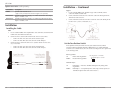
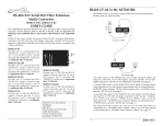
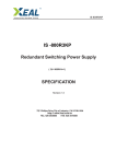
USER’S GUIDE
J/FE-CF-03
Stand-Alone media converter
• Fast Ethernet™
• Copper to Fiber
• 100Base-TX to 100Base-FX
Transition Networks J/FE-CF-03 Fast
Ethernet™ media converter connects 100
Mb/s twisted-pair copper cable to a duplex
100 Mb/s fiber-optic cable.
Use the J/FE-CF-03 series media converter
(or up to two media converters in series)
to extend over fiber, the distance between two 100BASE-TX devices (hub, switch,
workstation, etc.).
Part Number
Port One - Copper
Port Two - Duplex Fiber-Optic
J/FE-CF-03
RJ-45, 100Base-TX
100 m (328 ft)*
ST, 100Base-FX, 1300 nm multimode
2 km (1.2 miles)*
J/FE-CF-03(SC) RJ-45, 100Base-TX
100 m (328 ft)*
SC , 100Base-FX, 1300 nm multimode
2 km (1.2 miles)*
J/FE-CF-03(SM) RJ-45, 100Base-TX
100 m (328 ft)*
SC, 100Base-FX, 1300 nm singlemode
20 km (12.4 miles)*
J/FE-CF-03(LH) RJ-45, 100Base-TX
100 m (328 ft)*
SC, 100Base-FX, 1300 nm singlemode
40 km (24.9 miles)*
Single Fiber Optic (install as a pair)
Part Number
Port One - Copper
Port Two - Duplex Fiber-Optic
J/FE-CF-03-100 RJ-45, 100Base-TX
100 m (328 ft)*
SC, 1310 mn TX/1550 nm RX, 20 km
(12.4 miles)*
J/FE-CF-03-101 RJ-45, 100Base-TX
100 m (328 ft)*
SC, 1550 mn TX/1310 nm RX, 20 km
(12.4 miles)*
Note: Install the J/FE-CF-03-100 and the J/FE-CF-03-101 in the same network as local
and remote peers.
*Typical maximum cable distance. Actual distance is dependent upon the physical
characteristics of the network installation.
Installation . . . . . . . . . . . . . . . . . . . . .2
Operation . . . . . . . . . . . . . . . . . . . . . .5
Cable Specifications . . . . . . . . . . . . .6
Technical Specifications . . . . . . . . . .7
Troubleshooting . . . . . . . . . . . . . . . .8
Contact Us . . . . . . . . . . . . . . . . . . . . .9
Compliance Information . . . . . . . . .11
J/FE-CF-03
Options Accessories (sold separately)
Installation -- Continued
Part Number
Description
Copper
WMBS
Optional Wall Mount Brackets
Length: 3.2 in. (81 mm), Fits converter length: 3.9 in. (99 mm)
1.
Locate or build 100Base-TX compliant copper cables with male, RJ-45
connectors installed at both ends.
SPS-1872-SA
Optional External Power Supply; 18-72VDC Stand-Alone Wide-Input;
Output: 12.6VDC, 1.0 A
2.
Connect the RJ-45 connector at one end of the cable to the RJ-45 port on the
J/FE-CF-03 media converter.
SPS-1872-CC
Optional External Power Supply; 18-72VDC Piggy-Back Wide-Input;
Output: 12.6VDC, 1.0 A
3.
Connect the RJ-45 connector at the other end of the cable to the RJ-45 port on
the other device (switch, workstation, etc.).
Installation
Installing the Cable
Fiber
1.
Locate or build 100Base-FX compliant fiber cable with male, two-stranded TX
to RX connectors installed at both ends.
2.
Connect the fiber cables to J/FE-CF-03 media converter as described:
3.
•
Connect the male TX cable connector the female TX port.
•
Connect the male RX cable connector to the female RX port.
Connect the fiber cables to the other device (another media converter, hub,
etc.) as described:
•
•
Connect the male TX cable connector the female RX port.
Connect the male RX cable connector to the female TX port.
Set the Two-Position Switch
A two-position switch (located on the back of the media monverter) allows
selection of Auto-Negotiation and Full- or Half-Duplex. Use a small, flat-blade
screwdriver (or a similar device) to set the switch according to the site requirements
see the drawing below.
Auto-Negotiation:
UP
Enable Auto-Negotiation
DOWN
Disable Auto-Negotiation
Auto-Negotiation - UP=Enable
Full/Half Duplex - UP=Full
Full/Half Duplex:
2
24-hour Technical Support: 1-800-260-1312 -- International: 00-1-952-941-7600
UP
Full Duplex -- Advertises 100 Mb/s full-duplex only during AutoNegotiation.
DOWN
Half Duplex -- Used primarily when connecting to a hub. Operates at
100 Mb/s in duplex mode of the attached device.
[email protected] -- Click the “Transition Now” link for a live Web chat.
3
J/FE-CF-03
Installation -- Continued
Power the media converter
Operation
Using status LEDs
AC power:
Use the status LEDs to monitor the media converter operation in the network.
1.
Install the power adapter cord to the back of the media converter.
Power
Steady LED indicates connection to external AC power.
2.
Connect the power adapter plug to AC power.
Fiber
Steady LED indicates fiber link connection.
3.
Verify that the media converter is powered by observing the illuminated LED
power indicator light.
Copper
Steady LED indicates copper link connection.
DC power:
Consult the User’s Guide for the Transition Networks SPS1872-xx DC External
Power Supply for powering the media converter.
TX
RX
Fiber
Copper
100Base-FX
Power
100Base-TX
Auto-Negotiation
The Auto-Negotiation feature allows the media converter to be used with 100BaseTX ports. Using Auto-Negotiation, the media converter brings up the copper links
in the highest speed and mode possible for all attached network devices.
Full-Duplex network
In a full-duplex network, maximum cable lengths are determined by the type of
cables that are used. See page 1 (front cover) for the cable specifications for the
different J/FE-CF-03 models. (The 512-Bit Rule does not apply in a full-duplex
network.)
Half-Duplex network (512-Bit Rule)
In a half-duplex network, the maximum cable lengths are determined by the round
trip delay limitations of each Fast Ethernet™ collision domain. (A collision domain
is the longest path between any two terminal devices, e.g. a terminal, switch, or
router.)
The 512-Bit Rule determines the maximum length of cable permitted by calculating
the round-trip delay in bit-times (BT) of a particular collision domain. If the result
is less than or equal to 512 BT, the path is good.
For more information on the 512-Bit Rule, see the white paper titled “Collision
Domains” on the Transition Networks website at:
http://www.transition.com/learning/whitepapers/colldom_wp.htm
4
24-hour Technical Support: 1-800-260-1312 -- International: 00-1-952-941-7600
[email protected] -- Click the “Transition Now” link for a live Web chat.
5
J/FE-CF-03
Cable Specifications
Technical Specifications
The physical characteristics must meet or exceed IEEE 802.3™ specifications.
For use with Transition Networks Model J/FE-CF-03 or equivalent
Fiber cable
Product is certified by the manufacturer to comply with DHHS Rule 21/CFR,
Subchapter J applicable at the date of manufacture.
Bit Error Rate:
Singlemode fiber (recommended):
Multimode fiber (recommended):
Multimode fiber (optional):
<10-9
9 μm
62.5/125 μm
100/140, 85/140, 50/125 μm
J/FE-CF-03
Fiber Optic Transmitter Power:
Fiber Optic Receiver Sensitivity:
Link Budget:
1300 nm multimode
min: -19.0 dBm
max: -14.0 dBm
min: -30.0 dBm
max: -14.0 dBm
11.0 dB
J/FE-CF-03(SC)
Fiber Optic Transmitter Power:
Fiber Optic Receiver Sensitivity:
Link Budget:
1300 nm multimode
min: -19.0 dBm
max: -14.0 dBm
min: -30.0 dBm
max: -14.0 dBm
11.0 dB
J/FE-CF-03(SM) & (LH)
Fiber-optic Transmitter Power:
Fiber-optic Receiver Sensitivity:
Link Budget:
1300 nm singlemode
min: -15.0 dBm
max: -8.0 dBm
min: -31.0 dBm
max: -8.0 dBm
16.0 dB
J/FE-CF-03-100
J/FE-CF-03-101
Fiber-optic Transmitter Power:
Fiber-optic Receiver Sensitivity:
Link Budget:
1310 nm (TX)/1550 nm (RX) simplex
1550 nm (TX)/1310 nm (RX) simplex
min: -13.0 dBm
max: -6.0 dBm
min: -32.0 dBm
max: -3.0 dBm
19.0 dB
IEEE 802.3™
Data Rate:
100 Mb/s
Case Dimensions:
3.9" x 3.0" x 1.0" (100mm x 76mm x 25mm)
Shipping Weight:
2 pounds (0.9 kilograms)
Power Consumption:
2.8 watts, 200 mA @ 13.9 VDC
Power Supply DC Output:
12 VDC, 0.4 A (minimum)
minimum output regulation: 5%
Connector: 2.1mm barrel, center pin positive
MTBF*
48,135 hours
(MIL217F2 V5.0) (MIL-HDBK-217F)
128,553 hours (Bellcore7 V5.0)
Environment:
Tmra**:
0 to 60°C (32 to 140°F)
Storage Temp:
-20 to 85°C (-4 to 185°F)
Humidity:
5-95%, non-condensing
Altitude:
0-10,000 feet
Warranty:
Lifetime
**Manufacturer’s rated ambient temperature.
WARNING: Visible and invisible laser radiation when open. Do not stare into the
beam or view the beam directly with optical instruments. Failure to observe this
warning could result in an eye injury or blindness.
Copper cable
Category 5:
Gauge:
Attenuation:
Maximum Cable Distance:
Standards:
24 to 22 AWG
22.0 dB/100m @ 100 MHz
100 meters
• Straight-Through or Crossover cable may be used.
• Shielded Twisted-Pair (STP) or Unshielded Twisted-Pair (UTP) may be used.
• Pins 1&2 and 3&6 are the two active pairs in an Ethernet™ network .
• Use only dedicated wire pairs for the active pins:
(e.g., blue/white & white/blue, orange/white & white/orange, etc.)
• Do not use flat or silver satin wire.
WARNING: Use of controls, adjustments or the performance of procedures other than
those specified herein may result in hazardous radiation exposure.
CAUTION: Copper based media ports, e.g., Twisted Pair (TP) Ethernet, USB, RS232,
RS422, RS485, DS1, DS3, Video Coax, etc., are intended to be connected to intrabuilding (inside plant) link segments that are not subject to lightening transients or
power faults. Copper based media ports, e.g., Twisted Pair (TP) Ethernet, USB,
RS232, RS422, RS485, DS1, DS3, Video Coax, etc., are NOT to be connected to interbuilding (outside plant) link segments that are subject to lightening transients or power
faults. Failure to observe this caution could result in damage to equipment.
*MTBF is estimated using the predictability method. This method is based on MIL217F at 25°C ambient temperature, typical enclosure heat rise of 10°C, and nominal
operating conditions and parameters. Installation and configuration specific MTBF
estimates are available upon request. Contact Technical Support.
6
24-hour Technical Support: 1-800-260-1312 -- International: 00-1-952-941-7600
[email protected] -- Click the “Transition Now” link for a live Web chat.
7
J/FE-CF-03
Troubleshooting
If the media converter fails, isolate and correct the failure by determining the answers
to the following questions and then taking the indicated action:
1.
Is the Power LED on the media converter illuminated?
NO
•
Is the power adapter the proper type of voltage and cycle frequency for
the AC outlet?
•
Is the power adapter properly installed in the media converter and in the
outlet?
•
Contact Technical Support at (800) 260-1312.
YES
•
Proceed to step 2.
2.
Is the Fiber LED illuminated?
NO
•
Check the fiber cables for proper connection.
•
Verify that the TX and RX cables on the media converter are connected to
the RX and TX ports, respectively, on the other 100BASE-FX device.
•
Contact Technical Support at (800) 260-1312.
YES
•
Contact Technical Support at (800) 260-1312.
8
Technical support
Technical support is available 24 hours a day.
US and Canada:
1-800-260-1312
International:
00-1-952-941-7600
Transition NOW
Chat live via the Web with Transition Networks Technical Support.
Log onto www.transition.com and click the Transition Now link.
Web-Based seminars
Transition Networks provides seminars via live web-based training.
Log onto www.transition.com and click the Learning Center link.
Is the Copper LED illuminated?
NO
•
Check the copper cable for proper connection.
•
Contact Technical Support at (800) 260-1312.
YES
•
Proceed to step 3.
3.
Contact Us
24-hour Technical Support: 1-800-260-1312 -- International: 00-1-952-941-7600
E-Mail
Ask a question anytime by sending an e-mail to our technical support staff.
[email protected]
Address
Transition Networks
6475 City West Parkway
Minneapolis, MN 55344, U.S.A.
telephone:
952-941-7600
toll free:
800-526-9267
fax:
952-941-2322
[email protected] -- Click the “Transition Now” link for a live Web chat.
9
J/FE-CF-03
Declaration Of Conformity
Name of Mfg:
Transition Networks
6475 City West Parkway, Minneapolis MN 55344 U.S.A.
Model:
J/FE-CF-03 Series Media Converters
Part Number(s):
J/FE-CF-03, J/FE-CF-03(SC), J/FE-CF-03(SM), J/FE-CF-03(SH),
J/FE-CF-03(LH), J/FE-CF-03-100, J/FE-CF-03-101
Regulation:
EMC Directive 89/336/EEC
Purpose: To declare that the J/FE-CF-03 to which this declaration refers is in conformity
with the following standards.
EN 55022:1994; EN 55024:1998; FCC Part 15 Class A; EN 60950 A4:1997; UL 1950 (Power
Supply); 21 CFR subpart J
I, the undersigned, hereby declare that the equipment specified above conforms to the
above Directive(s) and Standard(s).
July 18, 2006_____
Stephen Anderson, Vice-President of Engineering
Date
Compliance Information
Power Supply is UL Listed
Power Supply is C-UL Listed (Canada)
CISPR22/EN55022 Class A + EN55204
CE Mark
FCC Regulations
This equipment has been tested and found to comply with the limits for a class A digital device,
pursuant to part 15 of the FCC rules. These limits are designed to provide reasonable protection
against harmful interference when the equipment is operated in a commercial environment. This
equipment generates, uses, and can radiate radio frequency energy and, if not installed and used in
accordance with the instruction manual, may cause harmful interference to radio communications.
Operation of this equipment in a residential area is likely to cause harmful interference, in which
case the user will be required to correct the interference at the user's own expense.
Canadian Regulations
This digital apparatus does not exceed the Class A limits for radio noise for digital apparatus set out
on the radio interference regulations of the Canadian Department of Communications.
Le présent appareil numérique n'émet pas de bruits radioélectriques dépassant les limites applicables
aux appareils numériques de la class A prescrites dans le Règlement sur le brouillage
radioélectrique édicté par le ministère des Communications du Canada.
European Regulations
Warning
This is a Class A product. In a domestic environment this product may cause radio interference in
which case the user may be required to take adequate measures.
Achtung !
Dieses ist ein Gerät der Funkstörgrenzwertklasse A. In Wohnbereichen können bei Betrieb dieses
Gerätes Rundfunkstörungen auftreten, in weichen Fällen der Benutzer für entsprechende
Gegenmaßnahmen werantwortlich ist.
Attention !
Ceci est un produit de Classe A. Dans un environment domestique, ce produit risque de créer des
interférences radioélectriques, il appartiendra alors à l'utilsateur de prende les measures spécifiques
appropriées.
In accordance with European Union Directive 2002/96/EC of the European Parliament
and of the Council of 27 January 2003, Transition Networks will accept post usage
returns of this product for proper disposal. The contact information for this activity can
be found in the 'Contact Us' portion of this document.
CAUTION: RJ connectors are NOT INTENDED FOR CONNECTION TO THE
PUBLIC TELEPHONE NETWORK. Failure to observe this caution could result in
damage to the public telephone network.
Der Anschluss dieses Gerätes an ein öffentlickes Telekommunikationsnetz in den EGMitgliedstaaten verstösst gegen die jeweligen einzelstaatlichen Gesetze zur Anwendung der
Richtlinie 91/263/EWG zur Angleichung der Rechtsvorschriften der Mitgliedstaaten über
Telekommunikationsendeinrichtungen einschliesslich der gegenseitigen Anerkennung ihrer
Konformität.
10
24-hour Technical Support: 1-800-260-1312 -- International: 00-1-952-941-7600
[email protected] -- Click the “Transition Now” link for a live Web chat.
11
J/FE-CF-03
Trademark Notice
All trademarks and registered trademarks are the property of their respective owners.
Copyright Restrictions
© 2003 Transition Networks.
All rights reserved. No part of this work may be reproduced or used in any form or by any means graphic, electronic, or mechanical - without written permission from Transition Networks.
12
Printed in the U.S.A.
33254.D