1
Operating Instruction Manual
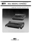
TOA MIXING CONSOLE
Model RX-208, RX-212, RX-216
RX-208
RX-212
RX-216
TOA ELECTRIC CO, LTD
KOBE, JAPAN
Contents
General Description . . . . . . . . . . . . . . . . . . . . . . . . . . . . . . . . . . . . . . . . . 2
Features . . . . . . . . . . . . . . . . . . . . . . . . . . . . . . . . . . . . . . . . . . . . . . . . . . . 2
Front Panel, Input Section . . . . . . . . . . . . . . . . . . . . . . . . . . . . . . . . . . . 3
Front Panel, Output Section . . . . . . . . . . . . . . . . . . . . . . . . . . . . . . . . . . 4
Meter Panel . . . . . . . . . . . . . . . . . . . . . . . . . . . . . . . . . . . . . . . . . . . . . . . . 5
Rear Panel (RX-208) . . . . . . . . . . . . . . . . . . . . . . . . . . . . . . . . . . . . . . . . . 6
Rear Panel (RX-212, RX-216) . . . . . . . . . . . . . . . . . . . . . . . . . . . . . . . . .
7
Connection Examples . . . . . . . . . . . . . . . . . . . . . . . . . . . . . . . . . . . . . . 8~10
How to use "channel patching" accessory jack . . . . . . . . . . . . . . . . . . 11
How to get a good mixing . . . . . . . . . . . . . . . . . . . . . . . . . . . . . . . . . . . . 12
Channel and Graphic Equalizers . . . . . . . . . . . . . . . . . . . . . . . . . . . 13~14
General Specification . . . . . . . . . . . . . . . . . . . . . . . . . . . . . . . . . . . . . . . . 14
Input & Output Specifications . . . . . . . . . . . . . . . . . . . . . . . . . . . . . . . . 15
Characteristic Diagrams . . . . . . . . . . . . . . . . . . . . . . . . . . . . . . . . . . . . . 16
Block Diagram . . . . . . . . . . . . . . . . . . . . . . . . . . . . . . . . . . . . . . . . . . . . . . 17
Level Diagram . . . . . . . . . . . . . . . . . . . . . . . . . . . . . . . . . . . . . . . . . . . . . . 18
Dimensional Diagrams . . . . . . . . . . . . . . . . . . . . . . . . . . . . . . . . . . . . . . . 18
Precautions
1. Each model of the RX-208, RX-212 and RX-216 has two
versions, 120V AC operation only and 220/240V AC operation
with a voltage selector. The voltage selector on the rear panel
of the 220/240V version should be check for proper setting
prior to operation as improper setting causes trouble. The
voltage selector is set for 240V operation at the factory.
VOLTAGE SELECTOR
AC220V
2. Power Switch
The power switch should be on after all connections have been completed.
3. XLR (Cannon) Connectors
The connectors are wired in the following manner: Pin 1 is ground (shield); pin 2 is
cold (low, minus); pin 3 is hot (high, plus).
4. Description of components and functions on the RX-208, RX-212 and RX-216.
In our Operating and Instruction Manual explanation of components and functions
is made according to our usage for them.
-1-
AC240V
General Description
The RX-208, 212 and 216, are mixing consoles with 8, 12 and 16 inputs respectively, 2
program outputs, 2 foldback outputs, and 1 echo output. Each input channel and line
output has a balanced, low impedance, transformer-isolated, XLR connector, and an
unbalanced, 1/4" jack. Each input channel includes an accessory send/receive jack for
inserting a signal processing device into the signal path, and a phantom power
ON/OFF switch for permitting use of a condenser microphone. An input level switch
and trim control on each input channel are provided to permit optimum settings. A
four-band equalizer is included on each input channel. A peak indicator LED on each
input detects excessive inputs and helps avoid clipping. A pan control on each input
channel assigns the fader output signal of the channel to programs L and R. A cue
switch on each input channel, stereo input, aux/echo input, program output, foldback
output and echo send allows monitoring the respective, pre-fader (pre-volume)
signals through the phones output. All faders are log-linear type with 60mm of travel.
Additional stereo inputs are used to connect a stereo playback deck, disk player and
other auxiliary equipment. Two independent foldback outputs are included, (prefader, pre-EQ) signals. An analog, electronic echo is built in, but can be bypassed (via
Echo Send/Return for external delay, reverb or special effects). Dual Graphic
Equalizers (1/1 octave, 9 bands) are switchable to either the program outputs or
foldback outputs. A fluorescent bargraph peak meter (2-color, vertical type) monitors
the outputs of the programs L and R, and foldbacks 1 and 2. These consoles are
designed for use in professional sound reinforcement systems, and provide versatile
functions to meet a wide range of requirements. The high performance and modular
construction assures reliability, easy maintenance, and serviceability.
Features
1. Balanced, low impedance, (transformer-isolated) XLR connector with an
unbalanced 1/4" jack on each input channel and line input.
2. An accessory send/receive jack on each input channel.
3. A phantom power switch on each input channel.
4. Input level switch and trim control on each input channel.
5. Four-band equalizer on each input channel.
6. Peak indicator LED on each input channel.
7. Cue switch on each input channel, stereo input, aux/echo input, program output,
foldback output and echo send.
8. All faders are log-linear type with 60mm travel.
9. Built-in, electronic analog echo unit.
10. Dual graphic equalizers (1/1 octave, 9 bands) are switchable to either the program
or foldback outputs.
11. Additional, stereo inputs for connecting a stereo playback deck, disk player and
other auxiliary equipment.
12. Fluorescent bargraph peak meters for monitoring the programs L and R, and
foldbacks 1 and 2.
-2-
Front Panel, Input Section
Peak Indicator
The peak indicator lights if clipping occurs in the pre-amp stage of the corresponding input
channel. When the light comes on, an adjustment must be made with the Input Level Selector
Switch and/or the Input Trim control.
Input Level Selector Switch (INPUT)
Selection is made in accordance with the output of the microphone or other equipment
connected to each input channel (XLR connector and phone jack). (—20, —40 and —60) dB
indicates the input sensitivity of the XLR connector input when the trim control is set at the "0"
position. The "UN-BAL" position permits using the phone jack input. The unbalanced input
sensitivity is —30dB when the trim control is set at the "0" position.
Input Trim Control (TRIM)
The input trim varies the gain of the pre-amplifier stage of each input channel, providing a
continuously variable control of gain in the range of 0 to —30dB from the input level switch
position. For instance, with the input level selector switch set at —60dB, the variable range is
between -60dB and -30dB.
High Equalizer Control (HIGH EQ)
The high control in each input channel alters the frequency response of the channel input,
allowing a variety of high frequency characteristics. The high control provides ±15dB of
continuously variable shelving equalization at 10kHz, having flat audio response at the
detented "0" position.
High-Mid Equalizer Control (HI-MID EQ)
The high-mid control provides ±15dB of continuously variable peaking equalization at 3kHz.
The detented "0" position is flat.
Low-Mid Equalizer Control (LOW MID EQ)
The low-mid control provides ±15dB of continuously variable peaking equalization at 300Hz,
having flat audio response at the detented "0" position.
Low Equalizer Control (LOW EQ)
The low control provides ±15dB of continuously variable shelving equalization at 100Hz,
having flat audio response at the detented "0" position.
Foldback Control 1 (FB 1)
The Foldback 1 control assigns the pre-equalizer, pre-fader input signal to the foldback 1
mixing bus. This control is used to route the input signal to stage monitor systems.
Foldback Control 2 (FB 2)
The Foldback 2 control assigns the pre-equalizer, pre-fader signal to the foldback 2 mixing
bus.
Echo Control (ECHO)
The echo control assigns the post-equalizer, post-fader signal to the echo bus.
Pan Pot (PAN)
This control assigns the fader output signal of the channel to the Program L, R mixing busses.
At the center position, the pan pot routes the signal equally to the L and R mixing busses.
Panning from one side to the other gradually assigns the input signal to either the Program L or
R mixing busses exclusively.
Writing Block
The name of the input equipment or microphone setting can be written in with an eraseable
felt pen or a wax pencil.
Input Fader
The fader provides continuously variable adjustment of the channel's output to the program L
and R mixing busses, and to the echo mixing bus. The nominal level is at the "0" position, with
the fader retaining a 10dB margin.
Cue Switch (CUE)
The cue switch is for monitoring the post-EQ, pre-fader signal in each input channel through
headphones. The switch is a "push-on push-off type. When more than two switches are "on",
the signals are combined.
-3-
Front Panel, Output Section
FB 1 Volume Control (FB1)
This control attenuates the echoreturn signals from the built-in echo
or an external echo unit and assigns
them to the FB 1 mixing bus.
Echo Time Control (T1 DELAY)
This control permits continuously
variable adjustment of the echo time
in either short or long ranges. The
short range is from 14m to 40m
Regeneration Control (T2 REGEN)
The T2 control is provided to adjust
the echo pattern (number of repeats)
of the internal analog delay.
seconds; the long range is from 40m
FB 2 Volume Control (FB2)
This control attenuates the echoreturn signals from the built-in echo
or an external echo unit and assigns
them to the FB 2 mixing bus.
to 140m seconds.
Echo Time Switch
(SHORT, LONG)
The switch changes the echo time to
either the short or the long range.
Stereo Input Switches (INPUT)
Each switch has two positions, aux
and phono. The aux position accepts
Headphone Jack
The headphone jack will accept any
stereo headphone with 8 ohms
impedance, or higher.
Phones Level Control (PHONES)
The phones level control adjusts
both the program L and R signals fed
line level signals such as tape
recorders. The phono position
provides direct input and RIAA
equalization for a turntable.
to the phones output and permits
stereo monitoring when the cue
switch is off. When the cue switch is
on, the control adjusts the corresponding cue signal. When two or
more of the cue switches are on, the
control adjusts the corresponding
combined cue signals.
FB 1 Volume Control (FB1)
This control attenuates the stereo
input signals, mixes them to a
monaural signal, and assigns them
to the FB 1 mixing bus.
FB2 Volume Control (FB2)
This control attenuates the stereo
input signals, mixes them to a
Pan Pot (PAN)
The pan pot control assigns the
signals from the built-in echo or
external echo unit to the program L
and R.
monaural signal, and assigns them
to the FB 2 mixing bus.
Balance Control (BALANCE)
control adjusts the level
This
balance of the stereo input signals
fed to the program L & R mixing
busses.
Echo Return Volume Control
(ECHO RETURN)
This control sets the signal level
from the built-in echo or from an
external echo unit and sends it
(through the pan control) to the program L and R.
Writing Block
The name of the input equipment
can be written in with an eraseable
felt pen or a wax pencil.
Stereo Input Volume Controls
(STEREO 1, STEREO 2)
These controls adjust the level of the
Echo Send Volume Control
(ECHO SEND)
This control is provided to adjust
the overall signal level of the echo
mix to the echo send output, or to the
internal analog delay.
stereo in 1 and 2 signals to be fed to
the program L and R mixing busses.
Cue Switch (CUE)
The cue switch is for monitoring the
pre-fader signal in each stereo input
channel through headphone. This
feature is useful for cueing the start
Cue Switch (CUE)
The cue switch is used for monitoring the signal prior to the Echo/Send
volume control.
of a tape or record.
Writing Block
The name of the input equipment or
microphone setting can be written in
with an eraseable felt pen or a wax
pencil.
Cue Switch (CUE)
The cue switch is used for monitor-
Program Fader L and R
(PGM L, PGM R)
The program faders control the
overall signal level of the program
mixes which are fed to the program
L & R outputs, and thus the output
level of the assigned internal power
amplifier.
ing the signal prior to
Echo/Return volume control.
the
FB Fader 1 and 2 (FB1, FB2)
These faders control the overall
signal level of the mixes which are
fed to FB outputs 1 and 2.
Cue Switches (CUE)
The cue switch is for monitoring the
pre-fader program signals through
headphone. This is useful for
independent
audition of the
program mixes.
Cue Switch (CUE)
The cue switch is used for monitor-
ing the signals prior to the FB 1 and 2
outputs.
-4-
Meter Panel
Program L Output Meter (PGM L)
The meter indicates the program L output
level.
RX-208, RX-212
Graphic Equalizer (EQUALIZATION)
Two channel, 1/1 octave graphic equalizer
with 9 bands (filters) enables 12dB of boost
and attenuation at each center frequency
with the "0" position of each filter providing
Program R Output Meter (PGM R)
The meter indicates the program R output
level.
FB 1 Output Meter (FB 1)
The meter indicates the FB 1 output level.
flat response. The graphic equalizer is
switchable to either the program or foldback
outputs, or "off for A-B comparison.
FB 2 Output Meter (FB 2)
The meter indicates the FB 2 output level.
Graphic Equalizer Selector Switch
Graphic Equalizer Selector Switch
(PGML, FB 1, OFF)
The 3-position switch assigns the equalizer
(PGM R, FB 2, OFF)
The 3-position switch assigns the equalizer
to either the program L or FB 1 circuits, with
to either the program R or FB 2 circuits, with
the "off" position completely removing the
equalizer from the signal flow path.
the "off" position completely removing the
equalizer from the signal flow path.
Caution
The graphic equalizer is normally used for either the PGM or FB mix. For normal operation, only one
button should be pressed. If the equalizer is not being used, the "OFF" button should be depressed.
RX-216
*The RX-216 is the same in its meter panel functions as the
RX-208 and RX-212.
FB 2 Output Meter
FB 1 Output Meter
Graphic Equalizer (EQUALIZATION)
Program R Output Meter
Program L Output Meter
Graphic Equalizer Selector Switch
Graphic Equalizer Selector Switch
(PGM L, FB 1, off)
(PGM R, FB 2, off)
-5-
Rear Panel (RX-208)
RX-208
Accessory Send/Receive Jacks
(ACCESSORY 1~8)
These jacks are provided as patching points
for inserting signal processing equipment
such as compressor/limiters, noise gate, etc.
An output impedance of the accessory send
and an input impedance of the accessory
receive are 10k ohms. Both nominal signals
levels are 0dB. Please refer to the detailed
explanation on page 11.
Program Line Output Connectors and Jacks
(LINE OUT, PGM L, R)
These connectors and jacks are the outputs
of the console deriving the signals after each
program master fader. The XLR connectors
are balanced, transformer-isolated, floating,
with an output impedance and nominal level
of 600 ohms and +4dB, respectively. The
phone jacks are unbalanced, with an output
impedance and nominal level of 600 ohms
and +4dB, respectively.
Channel Input, Unbalanced Jacks
(CHANNEL IN UN-BAL 1~8)
Phantom Power Switches
(PHANTOM 1~8)
The phantom power switch on
each input channel permits the
user to supply 48V DC through
the input connectors to a condenser microphone. If phantom
power is not required, the
switch must be in the "off" position.
Power Switch (POWER)
This switch provides AC power to the
console. Power should only be applied after
all audio connections have been completed.
Power Fuse
These 8 standard 1/4" phone jacks are
unbalanced with an input level of —30dB and
input impedance of 10k ohms. They will
accept low or high impedance sources. When
plugs are inserted into these jacks, the input
level switch must be set to the "UN-BAL"
position.
Channel Input, Balanced Connectors
(CHANNEL IN BAL 1~8)
The XLR connectors are balanced, transformer-isolated, floating, with an input impedance of 600 ohms, and will accept low impedance microphones as well as other impedance sources. When the XLR connectors
are employed, the input level switch on the
front panel must be set at the "BAL" posi-
tions. Proper adjustment of both input level
switch and trim control make it possible to
provide the optimum setting for each input.
Power Cord
Ground Terminal (GND)
The chassis must be grounded.
Ground Terminals (GND)
These may be used to provide ground connection
Foldback Line Output Connectors and Jacks
for tape decks or turntables.
(LINE OUT FB 1, 2)
These connectors and jacks are the foldback
outputs deriving the signals after each
foldback master fader. The XLR connectors
Stereo Input Pin Jacks (STEREO IN 1, 2)
Each stereo input has both AUX input and
PHONO input pin jacks that are switchable on the
front panel. RIAA equalization is provided on the
phono input for accepting turntables with
magnetic cartridges.
are balanced, transformer-isolated, floating,
with an output impedance and nominal level
of 600 ohms and +4dB, respectively. The
phone jacks are unbalanced, with an output
impedance and nominal level of 600 ohms
Recording Output Pin Jacks
and +4dB, respectively.
(REC OUT, PGM L, R)
The jacks are unbalanced and provide pre-graphic
EQ, pre-program fader signals for connection to
tape recorders.
Echo Output Jacks (ECHO SEND)
These jacks are unbalanced, with an output
impedance of 600 ohms. One jack is for +4dB
output and the other is for —20dB output. The
jacks are provided for connection to external
Auxiliary Echo Input Jack (AUX ECHO IN)
This standard phone jack is unbalanced and
echo machines. The +4dB jack can be used for
output cascading.
accepts low or high impedance sources at nominal
—20dB level. The jack sends an echo or reverb
return signal directly to the program L and R
Sub Input Jacks
These five jacks are directly connected to the
mixing busses. Inserting a plug in the jack
interrupts the return signal from the built-in echo
unit. The echo or reverb return signal can be
corresponding mixing busses (program L, R,
controlled by the echo return volume on the front
FB1, 2, and echo), and are provided for
panel.
(SUB IN PGM L, R, FB 1 , 2, ECHO)
cascade connection to expand the input
capacity.
–6–
Rear Panel (RX-212, RX-216)
The RX-212 and RX-216 are the same as the RX-208 in functions, except that the RX-212 has
12 input channels and the RX-216 has 16 input channels.
RX-212
Accessory Send/Receive Jacks
(ACCESSORY 1~12)
Program Line Output Connectors and lacks
(LINE OUT, PGM L, R)
Power Switch (POWER)
Phantom Power Switches
(PHANTOM 1~12)
Channel Input, Unbalanced Jacks
(CHANNEL IN UN-BAL 1~12)
Channel Input, Balanced Connectors
Power Fuse
(CHANNEL IN BAL 1~12)
Ground Terminals
(GND)
Stereo Input Pin Jacks (STEREO IN 1, 2)
Power Cord
Ground Terminal (GND)
Recording Output Pin Jacks
(REC OUT PGM L, PGM R)
Foldback Line Output Connectors and Jacks
Auxiliary Echo Input Jack (AUX ECHO IN)
(LINE OUT, FB1, 2)
Sub Input Jacks
Echo Output Jacks (ECHO SEND)
(SUB IN, PGM L, R, FB1 2, ECHO)
RX-216
Accessory Send/Receive Jacks
Program Line Out Connectors and Jacks
(ACCESSORY 1~16)
(LINE OUT, PGM L, R)
Power Switch (POWER)
Phantom Power Switches
(PHANTOM 1~16)
Power Fuse
Channel Input, Unbalanced Jacks
(CHANNEL IN UN-BAL 1~16)
Channel Input, Balanced Connectors
(CHANNEL IN BAL 1~16)
Power Cord
Ground Terminals (GND)
Ground Terminal (GND)
Stereo Input Pin Jacks (STEREO IN 1, 2)
Foldback Line Output Connectors
Recording Output Pin Jacks
and Jacks (LINE OUT, FB1, 2)
(REC OUT PGM L, PGM R)
Echo Output Jacks (ECHO SEND)
Auxiliary Echo Input Jack (AUX ECHO IN)
Sub Input Jacks
(SUB IN, PGM L, R, FB1 2, ECHO)
-7-
Connection Example
Main Speaker Systems (Right)
Main Speaker Systems (Left)
These XLR connectors are balanced,
transformer-isolated,
floating and accept low impedance sources of from +10dB to
—60dB nominal level. The input
level must be adjusted by the input level selector switch and
trim control.
Dual Power
Amplifier
Dual Power
Amplifier
Wireless Tuner
Keyboard
RX-208
Unbalanced input jacks accept
high
impedance
sources of from —30dB to
0dB nominal level. The input level switch on the
front panel must be set at
the "UN-BAL" position.
Ground for turntables
Record player with magnetic cartridge
The stereo input switch on the
front panel must be set at the
"PHONO" position.
Power Amplifier
Foldback Speaker Systems
(Self-Powered Speaker Systems)
Playback Tape Deck
The stereo input switch must
be set at the "AUX" position
with the nominal level of
-20dB
Foldback Speaker Systems
(Stage Monitor Speaker Systems)
Foldback Speaker Systems
(Self-Powered Speaker Systems)
Tape Deck for recording
-8-
Connection Example
Main Speaker Systems (Right)
4-way multiple driving
RX-216
-9-
Main Speaker Systems (Left)
4-way multiple driving
STAGE LAYOUT EXAMPLE
RX-212
- 10 -
How to use ''channel patching" accessory jack
The accessory jack (Tip, Ring, Sleeve) is provided on each input channel to allow insertion of
outboard signal processing devices (example: compressor/limiters, noise gate, equalizer, etc.)
into the signal path. The jack functions as both an output and an input (Tip=Receive,
Ring=Send, Sleeve=Shield). Connection cables for this purpose should be wired as illustrated
in Fig. 2.
Inserting a plug into the jack interrupts normal signal flow and places the external device into
the circuitry just prior to the input equalizer section. (See Fig. 1.)
Figure 1
*The connection marked of the shield
and sleeve is determined by the type of
equipment to be connected.
Figure 2
The accessory jacks may also be used as a direct output for each input channel, allowing direct
connection to a multi-track tape deck or use as an additional effects mix.
To unbalanced input of
other input channels to
mix dry signals with
processed signals.
Figure 3
Normal impedance of the accessory send is greater than 10k ohms and the receive impedance
is 10k ohms. Both nominal levels are at 0dB (0.775V).
- 11 -
How to get a good mixing
• Before connecting the equipment to the mixing console, check the impedance and level of
both. If the impedances and levels do not match, mixing will be very difficult and the S/N
ratio will also be adversely affected.
• Each input channel of the RX-208, RX-212 and RX-216 is provided with a Trim control.
Thorough understanding of the function of a Trim control will make mixing easier.
TRIM
• The
function of the Trim control is that the negative
feedback volume of the head amp is changed so that the
gain of the head amp can also be changed. Because of this,
OUTPUT
HEAD AMP
INPUT
enough dynamic range even for the high level signals is
ensured. Also, S/N ratio will be better by decreasing the
gain of the head amp proper.
For example, a microphone (balanced) with an output level of —50dB, a tape deck (balanced)
with an output level of 0dB, and a wireless tuner with an output level of —20dB are connected
to the console.
Microphone in
-50dB level
Tape Deck in Wireless tuner in
0dB level
-20dB level
First the Trim control must be turned down so that the
peak indicator will not be lit if an excessive signal comes in.
Nevertheless, if it is still on, the input level switch must be
rotated to the left 1 step. This can be applied to the "BAL"
inputs only, not to the "UN-BAL" inputs.
The input selector switch is set as shown in the left figure.
Trim control is set as shown in the left figure. Also, if the
volume balance of each instrument (microphone) is kept by
the Trim control the position of each channel fader will be
uniform, thus mixing becomes easier.
The faders in each channel are used in general between 0
and 10. If the hall is full and there is not enough volume, the
master fader must be turned up.
- 12 -
Channel and Graphic Equalizers
Equalization for music
The Graphic Equalizer is designed not only for use in preventing feedback and equalizing
uneven room frequency response to be flat, but also for equalizing frequency response to your
tastes and producing favourable sound for you. Fig. 1 shows each frequency band and its
corresponding auditory feeling. Fig. 2 and Table 1 show the relation between each musical
instrument and its frequency band. They can be of great help in the equalizer operation. (They
are referenced from a book entitled "Practical Guide for Concert".)
EQUALIZATION CHART
These sounds
The rhythm
are felt more
than really
heard. They
give a sense of
power. Too
much produces
section appears
here. Either a fat
or thin sound can
a muddy
sound.
Bass guitar-SnareToms.
be heard by misEQ here. Too much
becomes boomy.
Probably the most
important of all. Most
Upper vocal region.
Too much here will
all instruments
cause great fatigue,
contain harmonics
here.
300Hz boosting can
cause horn-like
sounds. 1k to 2k
sounds tinny. Too
and loss of speech
intelligence. Reducing
3k can bring vocals
on top.
much here sounds
like the telephone.
INSTRUMENT CHART
Presence range.
Sibilance
Great achievement
in overall level can
levels can be
controlled
be had here. Too
little causes a "far
away" sound.
here. Bright,
clean definition.
Figure 1
INSTRUMENT EQUALIZATION CHART
Acoustic guitar
Bass strings resonate between 70 to 120Hz, body around 300Hz.
Avoid boosting these to stop feedback. 3kHz and 5kHz give great
"clarity".
Electric guitar
Resonances differ— depending on type. Good full sounds around
300 to 500Hz. Clarity at 3kHz.
Bass guitar
Extreme lows are at 60 to 90Hz. "Pick" or "pluck" sounds are
around 800 to 1200Hz. Upper harmonics clarified about 3kHz.
Human voice
Good fullness at 150Hz. Watch for "boominess" around 250Hz.
Mid-range 10kHz.
Piano (Acoustic)
Bass strings resonate around 100Hz. Watch for sub-harmonics at
30 to 50Hz.
Piano (Electric)
Good mid-clarity at 3kHz to 5kHz thins out rapidly in high end. Be
careful around 1.5kHz to 2.5kHz to avoid the "bar room sound."
Organ
Usually dies under 200Hz. Has great mid-sounds around 1200 to
2000Hz. Top end cuts off at 6kHz.
Violin
Rich fullness at 400Hz. Natural raids around 1500 to 2500Hz.
Avoid "scratch" sounds at 8kHz.
Brass instruments
Watch for "hot" mids around 2kHz. Low end boost around 400Hz.
Top end clarity at 6kHz.
Bass drum
Great low "kick" at 40Hz. The mids at 2kHz gives the familiar
"punch."
Snare drum
Good fullness at 100Hz. The "crack" is boosted at 2kHz. The
snares extend to above 4kHz.
Tom Tom
The main fullness is around 200Hz. The mid punch extends to
4kHz.
Floor Tom
Same as tom, but extends down to 80Hz.
Hi Hat
Watch for the "gong" sound around 300Hz. Good "shimmer"
sounds are around 8kHz to 10kHz.
Cymbal overhead
Talk Box
About the same as hi-hat but has more low end around 150Hz.
Depending on the guitar sound driving it and the resonance of each
player's mouth, should have great "bite" around 1200Hz and dies
above 6kHz.
Table 1
Figure 2
- 13 -
Channel and Graphic Equalizers
Feedback Prevention
When the overall gain of a sound system is increased, feedback will occur at frequencies where
the system response has peaks. Suppose the system has uneven frequency response like that
shown in the following diagram.
The frequency at which feedback will occur when gain is increased is about 500Hz. In this
case, feedback may be prevented by attenuating levels at 500Hz by 3dB to 5dB with an
equalizer. If the overall gain is again gradually increased, feedback will occur next at about
125Hz. It may be stopped by attenuating the levels 3dB to 5dB at that frequency. In this
procedure, sufficient gain in the sound system is obtained before feedback.
General Specifications
Frequency Response
+0dB, -0.5dB
+0.5dB, -3dB
50Hz to 15kHz
20Hz to 30 kHz
Total Harmonic Distortion
0.5% at +4dB*/600 ohms at 1kHz
Hum and Noise
(20Hz to 20kHz, input termination of 150 ohms, Input level
switch at "BAL -60", Trim at "0", output termination of 600
ohms)
Equivalent Input Noise
-124dB* (20Hz — 20kHz)
-127dB* (IHF-A weighted)
S/N
64dB; PROGRAM OUT
(PGM Fader and one Input Fader at nominal
level)
64dB; FB OUT
(FB Fader and one FB control at nominal level)
Crosstalk
-60dB at 1kHz, input to output
Maximum Voltage Gain
84dB CH IN to PGM LINE OUT
84dB CH IN to FB LINE OUT
94dB CH IN to ECHO SEND
60dB CH IN to REC OUT
60dB CH IN to ACCESSORY SEND
44dB STEREO IN (AUX) to PGM LINE OUT
74dB STEREO IN (PHONO) to PGM LINE OUT
44dB AUX ECHO IN to PGM LINE OUT
24dB ACCESSORY RCV to PGM LINE OUT
10dB SUB IN to LINE OUT
Channel Equalizer (±15dB maximum)
LOW
100Hz
Shelving
LOW MID
300Hz Peaking
HI-MID
3kHz
Peaking
HIGH
10kHz
Shelving
Graphic Equalizer (±12dB maximum)
Center Frequency
63Hz, 125Hz, 250Hz, 500Hz, 1kHz, 2kHz,
4kHz, 8kHz, 16kHz
Internal Echo Unit
Delay Time SHORT 12msec—40msec
LONG
40msec—140msec
Peak Indicator
LED turns on when the pre-fader, post EQ signal reaches
6 dB before clip.
Phantom Power
48V DC is applied to balanced input transformer for
powering condenser microphones
Meter ("0" = +4dB* output at LINE OUT)
2 pairs of fluorescent bargraph meter for PGM L, R and FB 1,
2.
AC Line Voltage
AC Mains 50 Hz or 60 Hz
Power Consumption
RX-208
44W
RX-212
49W
RX-216
54W
Finish
Black panel, rosewood trim
Dimensions (W×D×H)
RX-208
564 × 687 × 206 mm (22-1/4" × 27" × 8-1/8")
RX-212
564 × 687 × 206 mm (22-1/4" × 27" × 8-1/8")
RX-216
684 × 687 × 206 mm (26-7/8" × 27" × 8-1/8")
Weight
RX-208
21kg (46.3 lbs)
RX-212
RX-216
Accessory
22kg (48.5 lbs)
26kg (57.3 lbs)
Fuse
*0dB is referenced to 0.775V RMS
Specifications are subject to change without notice.
- 14 -
Input & Output Specifications
INPUT SPECIFICATIONS
0dB is referenced to 0.775V RMS.
Actual
Load
Impedance
Input
For Use
With
Nominal
Input Level (Trim "0" to Trim "–30")
Connector
Sensitivity*
MAX. Before Clip
Nominal
50 to 600
ohms
–80dB (0.08mV) –60dB (0.78mV) to –30dB (25mV)
–60dB (0.78mV) –40dB (7.8mV) to –10dB (250mV)
–40dB (7.8mV) –20dB (78mV) to +10dB (2.5V)
–40dB (7.8mV) to –10dB (250mV)
–20dB (78mV) to +10dB (2.5V)
0dB (775V) to +30dB (25V)
10k ohms
–50dB (2.5mV)
–10dB (250mV) to +20dB (7.8V)
PHONE JACK
10k ohms
10k ohms
-20dB (78mV)
–0dB (775mV)
20dB (7.8mV)
3P PHONE
JACK***
10k ohms
PHONO 47k ohms
10k ohms
4 7k ohms
–40dB (7.8mV)
–70dB (0.25mV)
–20dB (78mV)
–50dB (2.5mV)
+10dB (2.5V)
–20dB (78mV)
PIN JACK
AUX ECHO IN
10k ohms
10k ohms
-40dB (7.8mV)
-20dB (78mV)
0dB (775mV)
PHONE JACK
SUB IN
10k ohms
10k ohms
–10dB (250mV)
+4dB (1.23mV)
+24dB (12.3mV)
PHONE JACK
BAL –60 550 ohms
BAL –40 800 ohms
BAL –20 900 ohms
CHANNEL IN
UN-BAL 25k ohms
ACCESSORY (RCV)
AUX
STEREO IN
–30dB (25mV) to 0dB (775mV)
OUTPUT SPECIFICATIONS
XLR-3-31
type**
RCA
0dB is referenced to 0.775V RMS.
Output Level
Output
Actual Source Impedance
Connector
For Use With Nominal
Nominal
MAX Before Clip
100 ohms
600 ohms
+4dB (1.23V)
+20dB (7.8V)
XLR-3-32
type**
and
PHONE JACK
90 ohms
64 ohms
600 ohms
+4dB (1.23V)
–20dB (78mV)
+20dB (7.8V)
-4dB (490mV)
PHONE JACK
PHONE JACK
REC OUT
1k ohms
10k ohms
–10dB (250mV)
+10dB (2.5V)
RCA PIN JACK
ACCESSORY (SEND)
1k ohms
10k ohms
0dB (775mV)
+20dB (7.8V)
3P PHONE JACK***
PHONES
18 ohms
8 ohms or higher
75mW/8 ohms,
0dB (775mV)
370mW/8 ohms,
+7dB (1.7V)
STEREO
PHONE JACK****
PGM L
PGM R
LINE OUT
FBl
FB2
ECHO SEND
+4
-20
*Sensitivity is the level required to produce a nominal speaker output level.
**All XLR type connectors are floating, balanced and transformer-isolated.
***ACCESSORY jacks (3P PHONE JACK) are wired: Tip=Receive, Ring=Send and Sleeve =Common
****Stereo phone jack is wired: Tip=Left, Ring=Right and Sleave=Common
Note:
As is described in the beginning of the operation manual, the XLR type connectors of the RX-208, RX-212 and RX-216 are wired as follows.
Pin No. 1 — Ground
Pin No. 2 — Cold (Low)
Pin No. 3 — Hot (High)
Specifications are subject to change without notice.
Caution:
The fuse rating for 120V AC operation is 2 amps., and 1 amp. for 220/240V AC operation. The fuse must always be replaced
with same type and rating.
- 15 -
Characteristic Diagrams
Frequency Response
Input EQ Characteristics
Graphic EQ Characteristics
- 16 -
- 17 NUMBER IN PARENTHESES=NOMINAL LOSS OR GAIN IN dB
NUMBER IN SQUARE BRACKETS=NOMINAL SIGNAL LEVEL
NUMBER IN TRIANSLE=GAIN OF AMPLIFIER IN dB
NUMBER IN RECTANGLE—LOSS OF ATTENUATOR IN dB
TRANSFORMER
AMPLIFIER
SWITCH
FADER OR LEVEL CONTROL
Level Diagram
Dimensional Diagrams
RX-208, RX-212
RX-216
The above dimensional diagram is for the RX-212.
Overall dimensional of the RX-208 is the same as the RX-212.
- 18 -
TOA ELECTRIC CO., LTD.
KOBE, JAPAN
Printed in Japan
133-02-573-2A