1
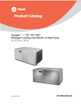
Packaged Rooftop
Air Conditioners
27 ½ to 50Ton - 60 Hz
Voyager™ Commercial
October 2001
RT-PRC007-EN
Introduction
Packaged Rooftop
Air Conditioners
Through the years,Trane has designed
and developed the most complete line of
Packaged Rooftop products available in
the market today.Trane was the first to
introduce the Micro —microelectronic
unit controls— and again moved ahead
with the introduction of the Voyager
Commercial products.
The Voyager Commercial line offers 27½
to 50 ton models; five sizes to meet the
changing demands of the commercial
rooftop market.
Voyager Commercial features cutting
edge technologies like the reliable 3-D®
Scroll compressors,Trane engineered
microprocessor controls, computeraided run testing, and Integrated
Comfort™ Systems. So, whether you’re
the contractor, the engineer, or the
owner you can be certain Voyager
Commercial Products are built to meet
your needs.
It’s HardTo Stop ATrane®.
Our customers demand thatTrane
products provide exceptional reliability,
meet stringent performance
requirements, and to be competitively
priced. Trane delivers with Voyager
Commercial.
©American Standard Inc. 2001
RT-PRC007-EN
Contents
Introduction
Features and Benefits
2
4
Application Considerations
10
Selection Procedure
12
Model Number Description
General Data
14
15
Performance Data
19
Performance Adjustment Factors
RT-PRC007-EN
Controls
18
28
Electric Power
32
Dimension and Weights
34
Mechanical Specifications
41
3
Features and
Benefits
Standard Features
• Factory installed and commissioned
microelectronic controls
• Trane 3-D™ Scroll Compressors
• Dedicated downflow or horizontal
configuration
• CV or VAV control
• FROSTAT™ coil frost protection on all
units
• Supply air overpressurization
protection on VAV units
• Supply airflow proving
• Emergency stop input
• Compressor lead-lag
• Occupied-Unoccupied switching
• Timed override activation
• FC supply fans
• UL and CSA listing on standard options
• Two inch standard efficiency filters
• Finish exceeds salt spray requirements
of ASTM B117
• Sloped condensate drain pan
4
Optional Features
• Electric heat
• Natural gas heat
• LP gas heat (kit only)
• Power Exhaust
• Barometric Relief
• High Efficiency 2”Throwaway Filters
• High Efficiency 4”Throwaway Filters
• High Efficiency supply fan motors
• Manual fresh air damper
• Economizer with dry bulb control
• Economizer with reference enthalpy
control
• Economizer with differential
(comparative) enthalpy control
• Inlet guide vanes on VAV units
• Variable frequency drives on VAV
units (with or without bypass)
• Service Valves
• Through-the-base electrical provision
• Factory mounted disconnect with
external handle (non-fused)
• Factory powered 15A GFI
convenience outlet
• Field powered 15A GFI convenience
outlet
• Integrated Comfort™ System Control
Option
• Ventilation Override
• Hinged Service Access
• Factory installed condenser coil
guards
• Black epoxy coated condenser coil
• Sloped stainless steel evaporator coil
drain pans
RT-PRC007-EN
Features and
Benefits
Trane 3-D® Scroll Compressor
Simple Design with 70% Fewer Parts
Fewer parts than an equal capacity
reciprocating compressor means
significant reliability and efficiency
benefits.The single orbiting scroll
eliminates the need for pistons,
connecting rods, wrist pins and valves.
Fewer parts lead to increased reliability.
Fewer moving parts, less rotating mass
and less internal friction means greater
efficiency than reciprocating
compressors.
Proven Design Through Testing and
Research
With over twenty years of development
and testing,Trane 3-D Scroll
compressors have undergone more
than 400,000 hours of laboratory testing
and field operation.This work combined
with over 25 patents makesTrane the
worldwide leader in air conditioning
scroll compressor technology.
One of two matched scroll plates —
the distinguishing feature of the scroll
compressor.
Chart illustrates low torque variation of
3-D Scroll compressor vs
reciprocating compressor.
TheTrane 3-D Scroll provides important
reliability and efficiency benefits.The 3-D
Scroll allows the orbiting scrolls to touch
in all three dimensions, forming a
completely enclosed compression
chamber which leads to increased
efficiency. In addition, the orbiting scrolls
only touch with enough force to create a
seal; there is no wear between the scroll
plates.The fixed and orbiting scrolls are
made of high strength cast iron which
results in less thermal distortion, less
leakage, and higher efficiencies. The
most outstanding feature of the 3-D
Scroll compressor is that slugging will
not cause failure. In a reciprocating
compressor, however, the liquid or dirt
can cause serious damage.
Low Torque Variation
The 3-D Scroll compressor has a very
smooth compression cycle; torque
variations are only 30 percent of that
produced by a reciprocating compressor.
This means that the scroll compressor
imposes very little stress on the motor
resulting in greater reliability. Low torque
variation reduces noise and vibration.
Suction Gas Cooled Motor
Compressor motor efficiency and
reliability is further optimized with the
latest scroll design. Cool suction gas
keeps the motor cooler for longer life and
better efficiency.
RT-PRC007-EN
5
Features and
Benefits
Quality and Reliability
Forced Combustion Blower
Negative Pressure Gas Valve
Hot Surface Ignitor
Drum and Tube Heat Exchanger
Micro Controls
Drum and Tube Heat Exchanger
The Micro provides unit control for
heating, cooling and ventilating utilizing
input from sensors that measure outdoor
and indoor temperature.
The drum and tube heat exchanger is
designed for increased efficiency and
reliability and has utilized improved
technology incorporated in the large roof
top commercial units for almost
20 years.
Quality and Reliability are enhanced
through the use of time-tested microprocessor controls and logic.
The Micro:
• prevents the unit from short cycling,
considerably improving
compressor life.
• ensures that the compressor will run
for a specific amount of time which
allows oil to return for better
lubrication, enhancing the reliability
of the commercial compressor.
The Voyager with the Micro reduces the
number of components required to
operate the unit, thereby reducing
possibilities for component failure.
6
The heat exchanger is manufactured
using aluminized steel with stainless
steel components for maximum
durability.The requirement for cycle
testing of heat exchangers is 10,000
cycles by ANSI Z21.47.This is the
standard required by both UL and AGA
for cycle test requirements.Trane
requires the design to be tested to 21/2
times this current standard.The drum
and tube design has been tested and
passed over 150,000 cycles which is over
15 times the current ANSI cycling
requirements.
The negative pressure gas valve will not
allow gas flow unless the combustion
blower is operating.This is one of our
unique safety features.
The forced combustion blower supplies
pre-mixed fuel through a single stainless
steel burner screen into a sealed drum
where ignition takes place. It is more
reliable to operate and maintain than a
multiple burner system.
The hot surface ignitor is a gas ignition
device which doubles as a safety device
utilizing a continuous test to prove the
flame.The design is cycle tested at the
factory for quality and reliability.
All the gas/electric rooftops exceed all
California seasonal efficiency
requirements.They also perform better
than required to meet the California NOx
emission requirements.
RT-PRC007-EN
Features and
Benefits
FC Fans with Inlet Guide Vanes
Ease of Installation
Trane’s forward-curved fans with inlet
guide vanes pre-rotate the air in the
direction of the fan wheel, decreasing
static pressure and horsepower,
essentially unloading the fan wheel.The
unloading characteristics of aTrane FC
fan with inlet guide vanes result in
superior part load performance.
Contractors look for lower installation
(jobsite) costs. Voyager’s conversionless
units provide many time and money
saving features.
Conversionless Units
The dedicated design units (either
downflow or horizontal) require no panel
removal or alteration time to convert in
the field — a major cost savings during
installation.
Improved Airflow
Excellent Part-Load Efficiency
The Scroll compressor’s unique design
allows it to be applied in a passive
parallel manifolded piping scheme,
something that a “recip” just doesn’t do
very well.
When the unit begins stage back at part
load it still has the full area and circuitry
of its evaporator and condenser coils
available to transfer heat. In simple
terms this means superior part-load
efficiencies (IPLV) and lower unit
operating costs.
Rigorous Testing
All of Voyager’s designs were rigorously
rain tested at the factory to ensure water
integrity.
Actual shipping tests are performed to
determine packaging requirements.
Units are test shipped around the
country. Factory shake and drop tested
as part of the package design process to
help assure that the unit will arrive at
your job site in top condition.
U-shaped airflow allows for improved
static capabilities.The need for high static
motor conversion is minimized and time
isn’t spent changing to high static
oversized motors.
Single Point Power
A single electrical connection powers the
unit.
Micro™
The function of the Micro replaces the
need for field installed anti-shortcycle
timer and time delay relays.The Micro
ensures that these controls are integral
to the unit.The contractor no longer has
to purchase these controls as options
and pay to install them.
The wiring of the low voltage
connections to the unit and the zone
sensors is as easy as 1-1, 2-2, and 3-3.
This simplified system makes it easier
for the installer to wire.
Rigging tests include lifting a unit into
the air and letting it drop one foot,
assuring that the lifting lugs and rails
hold up under stress.
We perform a 100% coil leak test at the
factory.The evaporator and condenser
coils are leak tested at 200 psig and
pressure tested to 450 psig.
All parts are inspected at the point of
final assembly. Sub-standard parts are
identified and rejected immediately.
Every unit receives a 100% unit run test
before leaving the production line to
make sure it lives up to rigorousTrane
requirements.
RT-PRC007-EN
7
Features and
Benefits
Easy to Service
Easy Access Low Voltage Terminal Board
Because today’s owners are very costconscious when it comes to service and
maintenance, theTrane Voyager was
designed with direct input from service
contractors.This valuable information
helped to design a product that would
get the serviceman off the job quicker
and save the owner money. Voyager
does this by offering:
Voyager’s Low VoltageTerminal Board is
external to the electrical control cabinet.
It is extremely easy to locate and attach
the thermostat wire.This is another cost
and time-saving installation feature.
A Simpler Design
The Voyager design uses fewer parts
than previous units. Since it is simpler in
design, it is easier to diagnose.
Micro
The Micro requires no special tools to
run the Voyager unit through its paces.
Simply place a jumper betweenTest 1
andTest 2 terminals on the Low Voltage
Terminal Board and the unit will walk
through its operational steps
automatically.
—The unit automatically returns
control to the zone sensor after
stepping through the test mode a
single time, even if the jumper is
left on the unit.
As long as the unit has power and the
“system on” LED is lit, the Micro is
operational.The light indicates that the
Micro is functioning properly.
The Micro features expanded diagnostic
capabilities when utilized withTrane’s
Integrated Comfort™ Systems.
Some Zone Sensor options have central
control panel lights which indicate the
mode the unit is in and possible
diagnostic information (dirty filters for
example).
8
Value
Low Ambient Cooling
All Voyager Commercial units have
cooling capabilities down to 0 F as
standard.
Power Exhaust Option
Provides exhaust of the return air when
using an economizer to maintain proper
building pressurization. Great for
relieving most building
overpressurization problems.
Micro Benefits
The Micro in the Voyager units has builtin anti-short-cycle timer, time delay relay
and minimum “on” time controls.These
controls are functions of the Micro and
are factory tested to assure proper
operation.
The Micro softens electrical “spikes” by
staging on fans, compressors and
heaters.
Intelligent Fallback is a benefit to the
building occupant. If a component goes
astray, the unit will continue to operate
at predetermined temperature setpoint.
Horizontal Discharge with
Power Exhaust Option
Intelligent Anticipation is a standard
feature of the Micro. It functions
constantly as the Micro and zone sensor
work together in harmony to provide
tighter comfort control than conventional
electro-mechanical thermostats.
RT-PRC007-EN
Features and
Benefits
VariTrac
Downflow and Horizontal Economizers
Trane’s changeover VAV System for light
commercial applications is also
available. Coupled with Voyager
Commercial, it provides the latest in
technological advances for comfort
management systems and can allow
thermostat control in every zone served
by VariTrac™.
The economizers come with three
control options dry bulb, enthalpy and
differential enthalpy. (Photo above
shows the three fresh air hoods on the
Horizontal Discharge Configuration).
VariTrac®
Central
Control Panel
Trane Communication Interface (TCI)
Available factory or field installed.This
module when applied with the Micro
easily interfaces withTrane’s Integrated
Comfort™ System.
Variable Frequency Drives (VFD)
TIME
CLOCK
INPUT/
STATUS
PANEL
EDIT
TERMINAL
Variable Frequency Drives are factory
installed and tested to provide supply fan
motor speed modulation. VFD’s, as
compared to inlet guide vanes or
discharge dampers, are quieter, more
efficient, and are eligible for utility
rebates.The VFD’s are available with or
without a bypass option. Bypass control
will simply provide full nominal airflow
in the event of drive failure.
Trane factory built roof curbs
Available for all units.
One of Our Finest Assets
Trane Commercial Sales Engineers are a
support group that can assist you with:
— Product
— Application
— Service
—Training
— Special Applications
— Specifications
— Computer Programs and more
RT-PRC007-EN
9
Application
Considerations
Exhaust Air Options
amounts of outdoor air into the building.
If, however, building pressure is not of a
critical nature, the non-modulating
exhaust fan may be sized for more than
50 percent of design supply airflow.
ConsultTable PD-16 for specific exhaust
fan capabilities with Voyager Commercial
units.
3
Barometric Relief Dampers
5
Bhp must be multiplied by the air density
ratio to obtain the actual operating bhp.
Voyager Commercial rooftop units offer
two types of exhaust systems:
Barometric relief dampers consist of
gravity dampers which open with
increased building pressure. As the
building pressure increases, the pressure
in the unit return section also increases,
opening the dampers and relieving air.
Barometric relief may be used to provide
relief for single story buildings with no
return ductwork and exhaust
requirements less than 25 percent.
1
Altitude Corrections
Power exhaust fan.
The rooftop performance tables and
curves of this catalog are based on
standard air (.075 lbs/ft). If the rooftop
airflow requirements are at other than
standard conditions (sea level), an air
density correction is needed to project
accurate unit performance.
From Figure PD-1, the air density ratio is
0.86.
When is it necessary to provide building
exhaust?
Whenever an outdoor air economizer is
used, a building generally requires an
exhaust system.The purpose of the
exhaust system is to exhaust the proper
amount of air to prevent over or underpressurization of the building.
A building may have all or part of its
exhaust system in the rooftop unit. Often,
a building provides exhaust external to
the air conditioning equipment.This
external exhaust must be considered
when selecting the rooftop exhaust
system.
2
Barometric relief dampers.
Application Recommendations
Power Exhaust Fan
The exhaust fan option is a dual,
nonmodulating exhaust fan with
approximately half the air-moving
capabilities of the supply fan system.The
experience ofTheTrane Company is that
a non-modulating exhaust fan selected
for 40 to 50 percent of nominal supply
cfm can be applied successfully.
The power exhaust fan generally should
not be selected for more than 40 to 50
percent of design supply airflow. Since it
is an on/off nonmodulating fan, it does
not vary exhaust cfm with the amount of
outside air entering the building.
Therefore, if selected for more than 40 to
50 percent of supply airflow, the building
may become underpressurized when
economizer operation is allowing lesser
10
Figure PD-1 shows the air density ratio at
various temperatures and elevations.
Trane rooftops are designed to operate
between 40 and 90 degrees Fahrenheit
leaving air temperature.
The procedure to use when selecting a
supply or exhaust fan on a rooftop for
elevations and temperatures other than
standard is as follows:
1
First, determine the air density ratio
using Figure PD-1.
2
Divide the static pressure at the
nonstandard condition by the air density
ratio to obtain the corrected static
pressure.
Use the actual cfm and the corrected
static pressure to determine the fan rpm
and bhp from the rooftop performance
tables or curves.
4
The fan rpm is correct as selected.
In order to better illustrate this procedure,
the following example is used:
Consider a 30-ton rooftop unit that is to
deliver 11,000 actual cfm at 1.50 inches
total static pressure (tsp), 55 F leaving air
temperature, at an elevation of 5,000 ft.
1
2
Tsp=1.50 inches/0.86=1.74 inches tsp.
3
From the performance tables: a 30-ton
rooftop will deliver 11,000 cfm at 1.74
inches tsp at 668 rpm and 6.93 bhp.
4
The rpm is correct as selected — 668
rpm.
5
Bhp = 6.93 x 0.86 = 5.96 .
Compressor MBh, SHR, and kw should
be calculated at standard and then
converted to actual using the correction
factors inTable PD-2. Apply these factors
to the capacities selected at standard cfm
so as to correct for the reduced mass
flow rate across the condenser.
RT-PRC007-EN
Application
Considerations
Heat selections other than gas heat will
not be affected by altitude. Nominal gas
capacity (output) should be multiplied by
the factors given inTable PD-3 before
calculating the heating supply air
temperature.
Acoustical Considerations
Proper placement of rooftops is critical to
reducing transmitted sound levels to the
building.The ideal time to make
provisions to reduce sound
transmissions is during the design
phase. And the most economical means
of avoiding an acoustical problem is to
place the rooftop(s) away from
acoustically critical areas. If possible,
rooftops should not be located directly
above areas such as: offices, conference
rooms, executive office areas and
classrooms. Instead, ideal locations
might be over corridors, utility rooms,
toilets or other areas where higher
sound levels directly below the unit(s)
are acceptable.
Several basic guidelines for unit
placement should be followed to
minimize sound transmission through
the building structure:
1
Never cantilever the compressor end of
the unit. A structural cross member must
support this end of the unit.
2
Locate the unit’s center of gravity which
is close to, or over, a column or main
support beam.
3
If the roof structure is very light, roof
joists must be replaced by a structural
shape in the critical areas described
above.
RT-PRC007-EN
4
If several units are to be placed on one
span, they should be staggered to
reduce deflection over that span.
It is impossible to totally quantify the
effect of building structure on sound
transmission, since this depends on the
response of the roof and building
members to the sound and vibration of
the unit components. However, the
guidelines listed above are experienceproven guidelines which will help reduce
sound transmissions.
Clearance Requirements
The recommended clearances identified
with unit dimensions should be
maintained to assure adequate
serviceability, maximum capacity and
peak operating efficiency. A reduction in
unit clearance could result in condenser
coil starvation or warm condenser air
recirculation. If the clearances shown are
not possible on a particular job, consider
the following:
Do the clearances available allow for
major service work such as changing
compressors or coils?
Do the clearances available allow for
proper outside air intake, exhaust air
removal and condenser airflow?
If screening around the unit is being
used, is there a possibility of air
recirculation from the exhaust to the
outside air intake or from condenser
exhaust to condenser intake?
Actual clearances which appear
inadequate should be reviewed with a
localTrane sales engineer.
When two or more units are to be placed
side by side, the distance between the
units should be increased to 150 percent
of the recommended single unit
clearance.The units should also be
staggered for two reasons:
1
To reduce span deflection if more than
one unit is placed on a single span.
Reducing deflection discourages sound
transmission.
2
To assure proper diffusion of exhaust air
before contact with the outside air intake
of adjacent unit.
Duct Design
It is important to note that the rated
capacities of the rooftop can be met only
if the rooftop is properly installed in the
field. A well designed duct system is
essential in meeting these capacities.
The satisfactory distribution of air
throughout the system requires that
there be an unrestricted and uniform
airflow from the rooftop discharge duct.
This discharge section should be straight
for at least several duct diameters to
allow the conversion of fan energy from
velocity pressure to static pressure.
However, when job conditions dictate
elbows be installed near the rooftop
outlet, the loss of capacity and static
pressure may be reduced through the
use of guide vanes and proper direction
of the bend in the elbow.The high
velocity side of the rooftop outlet should
be directed at the outside radius of the
elbow rather than the inside.
11
Selection
Procedure
Selection ofTrane commercial air
conditioners is divided into five basic
areas:
1
Cooling capacity
2
Heating capacity
3
Air delivery
4
Unit electrical requirements
5
Unit designation
b
2” Hi-efficiency throwaway filters.
c
Step 4 — Determine total required unit
cooling capacity:
Exhaust fan.
d
Required capacity = total peak load +
O.A. load + supply air fan motor heat.
Economizer cycle.
Step 1 — A summation of the peak
cooling load and the outside air
ventilation load shows: 27.75 tons + 1.52
tons = 29.27 required unit capacity. From
Table 18-2, 30-ton unit capacity at 80 DB/
67 WB, 95 F entering the condenser and
12,000 total peak supply cfm, is 30.0 tons.
Thus, a nominal 30-ton unit is selected.
1
Step 2 — Having selected a nominal 30ton unit, the supply fan and exhaust fan
motor bhp must be determined.
Summer design conditions — 95 DB/
Supply Air Fan:
76 WB, 95 F entering air to condenser.
Determine unit static pressure at design
supply cfm:
Factors Used In Unit Cooling Selection:
2
Summer room design conditions —
76 DB/66 WB.
External static pressure
1.20 inches
Heat exchanger
.14 inches
3
(Table PD-14)
Total peak cooling load — 321 MBh (27.75
tons).
High efficiency filter 2”
4
Economizer
Total peak supply cfm — 12,000 cfm.
.09 inches
(Table PD-14)
8
Outside air ventilation cfm and load —
1200 cfm and 18.23 MBh (1.52 tons).
9
Unit accessories include:
a
Aluminized heat exchanger — high heat
module.
12
FromTable PD-4 unit capacity at 81.5 DB.
67 WB entering the evaporator, 12000
supply air cfm, 95 F entering the
condenser is 361 MBh (30.1 tons) 279
sensible MBh.
Step 6 — Determine leaving air
temperature:
Unit sensible heat capacity, corrected for
supply air fan motor heat 279 - 20.6 =
258.4 MBh.
Supply air dry bulb temperature
difference = 258.4 MBh ÷ (1.085 x 12,000
cfm) = 19.8 F.
Supply air dry bulb: 81.5 - 19.8 = 61.7.
Btu/lb leaving enthalpy = h (ent WB) =
31.62
Using total cfm of 12,000 and total
static pressure of 1.50 inches, enterTable
PD-12.Table PD-12 shows 7.27 bhp with
652 rpm.
Return air cfm — 4250 cfm.
Step 5 — Determine unit capacity:
1.50 inches
(Table PD-14)
External static pressure — 1.0 inches.
7
Capacity = 321 + 18.23 + 20.6 =
359.8 MBh (30 tons)
Unit enthalpy difference = 361 ÷ (4.5 x
12,000) = 6.7
Unit total static pressure
Return air temperatures — 80 DB/66 WB.
From Figure SP-1, the supply air fan
motor heat for 7.27 bhp = 20.6 MBh.
.076 inches
5
6
A psychrometric chart can be used to
more accurately determine the mixture
temperature to the evaporator coil.
Step 3 — Determine evaporator coil
entering air conditions. Mixed air dry
bulb temperature determination.
Leaving enthalpy = 31.62 Btu/lb 6.7 Btu/lb = 24.9 Btu/lb.
FromTable PD-1, the leaving air wet bulb
temperature corresponding to an
enthalpy of 24.9 Btu/lb = 57.5.
Leaving air temperatures =
61.7 DB/57.5 WB
Using the minimum percent of OA (1,200
cfm ÷ 12,000 cfm = 10 percent),
determine the mixture dry bulb to the
evaporator. RADB + %OA (OADB - RADB)
= 80 + (0.10) (95 - 80) = 80 + 1.5 = 81.5F
Approximate wet bulb mixture
temperature:
RAWB + OA (OAWB - RAWB) = 66 + (0.10)
(76-66) = 68 + 1 = 67 F.
RT-PRC007-EN
Selection
Procedure
Heating capacity selection:
1
Winter outdoor design conditions—5 F.
2
Total return air temperature — 72 F.
3
Winter outside air minimum ventilation
load and cfm — 1,200 cfm and 87.2 MBh.
4
Peak heating load 225 MBh.
Utilizing unit selection in the cooling
capacity procedure.
Mixed air temperature = RADB + %O.A.
(OADB - RADB) = 72
+ (0.10) (0-72) = 64.8 F.
Supply air fan motor heat temperature
rise = 20,600 BTU ÷ (1.085 x 12,000) cfm
= 1.6 F.
Mixed air temperature entering heat
module = 64.8 + 1.6 = 66.4 F.
Total winter heating load = peak heating
+ ventilation load - total fan motor heat =
225 + 87.2 - 20.6 = 291.6 MBh.
Electric Heating System
Unit operating on 480/60/3 power supply.
FromTable PD-9, kw may be selected for
a nominal 30-ton unit operating on 480volt power.The high heat module — 90
KW or 307 MBh will satisfy the winter
heating load of 291.6 MBh.
Table PD-9 also shows an air
temperature rise of 23.6 F for 12,000 cfm
through the 90 kw heat module.
Unit supply temperature at design
heating conditions = mixed air
temperature + air temperature rise = 66.4
+ 23.6 = 90 F.
Natural Gas Heating System
Assume natural gas supply — 1000 Btu/
ft3. FromTable PD-11, select the high heat
module (486 MBh output) to satisfy 291.6
at unit cfm.
Table PD-11 also shows air temperature
rise of 37.3 F for 12,000 cfm through
heating module.
The supply air fan motor selected in the
previous cooling capacity determination
example was 7.27 bhp with 652 rpm.
Thus, the supply fan motor selected is 7.5
hp.
To select the drive, enterTable PD-15 for
a 30-ton unit. Select the appropriate
drive for the applicable rpm range. Drive
selection letter C with a range of 650
rpm, is required for 652 rpm. Where
altitude is significantly above sea level,
useTable PD-2 and PD-3, and Figure PD-1
for applicable correction factors.
Unit Electrical Requirements
Unit supply temperature design heating
conditions = mixed air temperature + air
temperature rise = 66.4 + 37.3 = 103.7 F.
Selection procedures for electrical
requirements for wire sizing amps,
maximum fuse sizing and dual element
fuses are given in the electrical service
selection of this catalog.
Air Delivery Procedure
Unit Designation
Supply air fan bhp and rpm selection.
Unit supply air fan performance shown
inTable PD-12 includes pressure drops
for dampers and casing losses. Static
pressure drops of accessory
components such as heating systems,
and filters if used, must be added to
external unit static pressure for total
static pressure determination.
After determining specific unit
characteristics utilizing the selection
procedure and additional job
information, the complete unit model
number can be developed. Use the
model number nomenclature on page
14.
STANDARD MOTOR
HIGH EFFICIENCY MOTOR
Figure SP-1 — Fan Motor Heat
120
FAN MOTOR HEAT - MBH
110
100
90
80
70
60
50
40
30
20
10
0
0
5
10
15
20
25
30
35
40
MOTOR BRAKE HORSE POWER
RT-PRC007-EN
13
Model
Number
Description
YC
12
D
3
480
456
A
7
4
8
H
9
A 1
10 11
A 4
12 13
F
14
D 1 A
15 16 17
0 0 0 0 0 0 0
18 19 20 21 22 23 24
0 0
25 26
0 0 05
27 28 29
Digit 1, 2 — Unit Function
Digit 13 — Supply Fan Motor, HP
Digit 16 — System Control
TC = DX Cooling, No Heat
TE = DX Cooling, Electric Heat
YC = DX Cooling, Natural Gas Heat
1 = 7.5 Hp Std. Eff.
2 = 10 Hp Std. Eff.
3 = 15 Hp Std. Eff.
4 = 20 Hp Std. Eff.
5 = 7.5 Hp Hi. Eff.
6 = 10 Hp Hi. Eff.
7 = 15 Hp Hi. Eff.
8 = 20 Hp Hi. Eff.
1 = Constant Volume
2 = VAV Supply Air Temperature Control
w/o Inlet Guide Vanes
3 = VAV Supply Air Temperature Control
w/Inlet Guide Vanes
4 = VAV Supply Air Temperature Control
w/Variable Frequency Drive w/o Bypass
5 = VAV Supply Air Temperature Control
w/Variable Frequency Drive and Bypass
Note: Zone sensors are not included with
option and must be ordered as a separate
accessory.
Digit 3 — Unit Airflow Design
D = Downflow Configuration
H = Horizontal Configuration
Digit 4, 5, 6 — Nominal Cooling Capacity
330 = 27½ Tons
360 = 30 Tons
420 = 35 Tons
480 = 40 Tons
600 = 50 Tons
Digit 7 — Major Development Sequence
A = First
Digit 8 — Power Supply (See Note 1)
E = 208/60/3
F = 230/60/3
4 = 460/60/3
5 = 575/60/3
Digit 9 — Heating Capacity (See Note 4)
0 = No Heat (TC only)
L = Low Heat (YC only)
H = High Heat (YC only)
Note: When second digit is “E” for Electric
Heat, the following values apply in the ninth
digit.
A = 36 KW
B = 54 KW
C = 72 KW
D = 90 KW
E = 108 KW
Digit 14 — Supply Air Fan Drive
Selections (See Note 3)
A
B
C
D
E
F
G
=
=
=
=
=
=
=
550 RPM
600 RPM
650 RPM
700 RPM
750 RPM
790 RPM
800 RPM
H
J
K
L
M
N
=
=
=
=
=
=
500 RPM
525 RPM
575 RPM
625 RPM
675 RPM
725 RPM
Digit 15 — Fresh Air Selection
A
B
C
D
=
=
=
=
E =
F =
G =
H =
No Fresh Air
0-25% Manual Damper
0-100% Economizer, Dry Bulb Control
0-100% Economizer, Reference
Enthalpy Control
0-100% Economizer, Differential
Enthalpy Control
“C” Option and Low Leak Fresh
Air Damper
“D” Option and Low Leak Fresh
Air Damper
“E” Option and Low Leak Fresh
Air Damper
Digit 17 - 29 — Miscellaneous
A = Service Valves (See Note 2)
B = Through the Base Electrical Provision
C = Non-Fused Disconnect Switch with
External Handle
D = Factory-Powered 15A GFI
Convenience Outlet and Non-Fused
Disconnect Switch with
External Handle
E = Field-Powered 15A GFI
Convenience Outlet
F = ICS Control Option — Trane
Communication Interface, Supply Air
Sensing and Clogged Filter Switch
G = Ventilation Override
H = Hinged Service Access
J = Condenser Coil Guards
K = LonTalk Communication Interface
L = Special
M = Stainless Steel Drain Pans
N = Black Epoxy Coated Condenser Coil
Digit 10 Design Sequence
A = First
Digit 11 — Exhaust
0 = None
1 = Barometric Relief
(Available w/Economizer only)
2 = Power Exhaust Fan
(Available w/Economizer only)
Digit 12 — Filter
A = Standard 2” Throwaway Filters
B = High Efficiency 2” Throwaway Filters
C = High Efficiency 4” Throwaway Filters
Note:
1. All voltages are across the line starting only.
2. Option includes Liquid, Discharge, Suction Valves.
3. Supply air fan drives A thru G are used with 27½-35 ton units only and drives H thru N are used with 40 & 50
ton units only.
4. Electric Heat KW ratings are based upon voltage ratings of 240/480/600 V. Voltage offerings are as follows (see
table PD-9 for additional information):
Tons
27½ to 35
40 and 50
Voltage
240
480
600
240
480
600
36
x
x
54
x
x
x
x
x
x
KW
72
90
x
x
x
x
x
x
x
x
108
x
x
5. The service digit for each model number contains 29 digits; all 29 digits must be referenced.
14
RT-PRC007-EN
General Data
Table GD-1 — General Data — 27 1/2 - 30 Tons
27 1/2 Ton
Cooling Performance1
Nominal Gross Capacity
Natural Gas Heat2
Heating Input (BTUH)
First Stage
Heating Output (BTUH)
First Stage
Steady State Efficiency (%)3
No. Burners
No. Stages
Gas Connection Pipe Size (in.)
Electric Heat
KW Range5
Capacity Steps:
Compressor
Number/Type
Size (Nominal)
Unit Capacity Steps (%)
Motor RPM
Outdoor Coil — Type
Tube Size (in.) OD
Face Area (sq. ft.)
Rows/Fins Per Inch
Indoor Coil — Type
Tube Size (in.) OD
Face Area (sq. ft.)
Rows/Fins Per Foot
Refrigerant Control
No. of Circuits
Drain Connection No./Size (in)
Type
Outdoor Fan Type
No. Used/Diameter
Drive Type/No. Speeds
CFM
No. Motors/HP/RPM
Indoor Fan Type
No. Used
Diameter/Width (in)
Drive Type/No. Speeds
No. Motors/HP
Motor RPM
Motor Frame Size
Exhaust Fan Type
No. Used/Diameter (in)
Drive Type/No. Speeds/Motors
Motor HP/RPM
Motor Frame Size
Filters — Type Furnished
No./ Recommended Size (in)6
Refrigerant Charge (Lbs of R-22)4
Minimum Outside Air Temperature
For Mechanical Cooling
30 Ton
329,000
363,000
Low
350,000
250,000
283,500
202,500
81.00
1
2
3
/4
High
600,000
425,000
486,000
344,500
81.00
2
2
1
Low
350,000
250,000
283,500
202,500
81.00
1
2
3
/4
High
600,000
425,000
486,000
344,500
81.00
2
2
1
27-90
2
27-90
2
2/Scroll
10/15
100/40
3450
Lanced
3
/8
51.33
2/16
Hi-Performance
1
/2
31.67
2/180
TXV
1
1/1.25
PVC
Propeller
3/28.00
Direct/1
24,800
3/1.10/1125
FC
1
22.38/22.00
Belt/1
1/7.50/10.00
1760
213/215T
Propeller
2/26.00
Direct/2/2
1.0/1075
48
Throwaway
16/16 x 20 x 2
46.00
2/Scroll
15
100/50
3450
Lanced
3
/8
51.33
2/16
Hi-Performance
1
/2
31.67
2/180
TXV
1
1/1.25
PVC
Propeller
3/28.00
Direct/1
24,800
3/1.10/1125
FC
1
22.38/22.00
Belt/1
1/7.50/10.00
1760
213/215T
Propeller
2/26.00
Direct/2/2
1.0/1075
48
Throwaway
16/16 x 20 x 2
46.60
0F
0F
Notes:
1. Cooling Performance is rated at 95 F ambient, 80 F entering dry bulb, 67 F entering wet bulb. Gross capacity does not include the effect of fan motor heat. Rated and tested in
accordance with the Unitary Large Equipment certification program, which is based on ARI Standard 340/360-93.
2. Heating Performance limit settings and rating data were established and approved under laboratory test conditions using American National Standards Institute standards.
Ratings shown are for elevations up to 4,500 feet.
3. Steady State Efficiency is rated in accordance with DOE test procedures.
4. Refrigerant charge is an approximate value. For a more precise value, see unit nameplate and service instructions.
5. Maximum KW @ 208V = 41, @ 240V = 54.
6. Filter dimensions listed are nominal. For actual filter and rack sizes see the Unit Installation, Operation, Maintenance Guide.
RT-PRC007-EN
15
General Data
Table GD-2— General Data — 35-40 Ton
35 Ton
Cooling Performance1
Nominal Gross Capacity
Natural Gas Heat2
Heating Input (BTUH)
First Stage
Heating Output (BTUH)
First Stage
Steady State Efficiency (%)3
No. Burners
No. Stages
Gas Connection Pipe Size (in.)
Electric Heat
KW Range5
Capacity Steps:
Compressor
Number/Type
Size (nominal)
Unit Capacity Steps (%)
Motor RPM
Outdoor Coil — Type
Tube Size (in.) OD
Face Area
Rows/Fins Per Inch
Indoor Coil — Type
Tube Size (in.) OD
Face Area (sq. ft.)
Rows/Fins Per Foot
Refrigerant Control
No. of Circuits
Drain Connection No./Size (in)
Type
Outdoor Fan Type
No. Used/Diameter
Drive Type/No. Speeds
CFM
No. Motors/HP/RPM
Indoor Fan Type
No. Used
Diameter/Width (in)
Drive Type/No. Speeds
No. Motors/HP
Motor RPM
Motor Frame Size
Exhaust Fan Type
No. Used/Diameter (in)
Drive Type/No. Speeds/Motors
Motor HP/RPM
Motor Frame Size
Filters — Type Furnished
No./Recommended Size (in)6
Refrigerant Charge (Lbs of R-22)4
Minimum Outside Air Temperature
For Mechanical Cooling
40 Ton
417,000
513,000
Low
350,000
250,000
283,500
202,500
81.00
1
2
3
/4
High
600,000
425,000
486,000
344,500
81.00
2
2
1
Low
400,000
300,000
324,000
243,000
81.00
1
2
3
/4
High
800,000
600,000
648,000
486,000
81.00
2
2
1
27-90
2
41-108
2
2/Scroll
15
100/50
3450
Lanced
3
/8
51.33
2/16
Hi-Performance
1
/2
31.67
3/180
TXV
1
1/1.25
PVC
Propeller
3/28.00
Direct/1
24,800
3/1.10/1125
FC
1
22.38/22.00
Belt/1
1/7.50/10.00/15.00
1760
213/215/254T
Propeller
2/26.00
Direct/2/2
1.0/1075
48
Throwaway
16/16 x 20 x 2
51.50
3/Scroll
15/15/10
100/60/40
3450
Lanced
3
/8
69.79
2/16
Hi-Performance
1
/2
37.50
3/180
TXV
2
1/1.25
PVC
Propeller
4/28.00
Direct/1
31,700
4/1.10/1125
FC
1
25.00/25.00
Belt/1
1/10.00/15.00
1760
215/254T
Propeller
2/26.00
Direct/2/2
1.0/1075
48
Throwaway
17/16 x 20 x 2
26.00/47.10 per circuit
0F
0F
Notes:
1. Cooling Performance is rated at 95 F ambient, 80 F entering dry bulb, 67 F entering wet bulb. Gross capacity does not include the effect of fan motor heat. Rated and tested
in accordance with the Unitary Large Equipment certification program, which is based on ARI Standard 340/360-93.
2. Heating Performance limit settings and rating data were established and approved under laboratory test conditions using American National Standards Institute standards.
Ratings shown are for elevations up to 4,500 feet.
3. Steady State Efficiency is rated in accordance with DOE test procedures.
4. Refrigerant charge is an approximate value. For a more precise value, see unit nameplate and service instructions.
5. Maximum KW @ 208V = 41, @ 240V = 54.
6. Filter dimensions listed are nominal. For actual filter and rack sizes see the Unit Installation, Operation, Maintenance Guide.
16
RT-PRC007-EN
General Data
Table GD-3— General Data — 50 Ton
Table GD-4 — Economizer Outdoor Air
Damper Leakage (Of Rated Airflow)
50 Ton
Cooling Performance1
Nominal Gross Capacity
Natural Gas Heat2
Heating Input (BTUH)
First Stage
Heating Output (BTUH)
First Stage
Steady State Efficiency (%)3
No. Burners
No. Stages
Gas Connection Pipe Size (in.)
Electric Heat
KW Range5
Capacity Steps:
Compressor
Number/Type
Size (nominal)
Unit Capacity Steps (%)
Motor RPM
Outdoor Coil — Type
Tube Size (in.) OD
Face Area (sq. ft.)
Rows/Fins Per Inch
Indoor Coil — Type
Tube Size (in.) OD
Face Area (sq. ft.)
Rows/Fins Per Foot
Refrigerant Control
No. of Circuits
Drain Connection No./Size (in)
Type
Outdoor Fan Type
No. Used/Diameter
Drive Type/No. Speeds
CFM
No. Motors/HP/RPM
Indoor Fan Type
No. Used
Diameter/Width (in)
Drive Type/No. Speeds
No. Motors/HP
Motor RPM
Motor Frame Size
Exhaust Fan Type
No. Used/Diameter (in)
Drive Type/No. Speeds/Motors
Motor HP/RPM
Motor Frame Size
Filters — Type Furnished
No./Recommended Size (in)6
Refrigerant Charge (Lbs of R-22)4
Minimum Outside Air Temperature
For Mechanical Cooling
616,000
Low
400,000
300,000
324,000
243,000
81.00
1
2
3
/4
High
800,000
600,000
648,000
486,000
81.00
2
2
1
∆P Across Dampers (In. WC)
0.5 (In.)
1.0 (In.)
Standard
1.5 %
2.5 %
Optional “Low Leak”
0.5 %
1.0 %
Note: Above data based on tests completed in
accordance with AMCA Standard 575.
41-108
2
3/Scroll
14
100/67/33
3450
Lanced
3
/8
69.79
2/16
Hi-Performance
1
/2
37.50
4/164
TXV
2
1/1.25
PVC
Propeller
4/28.00
Direct/1
31,700
4/1.10/1125
FC
1
25.00/25.00
Belt/1
1/10.00/15.00/20.00
1760
215/254/256T
Propeller
2/26.00
Direct/2/2
1.0/1075
48
Throwaway
17/16 x 20 x 2
25.70/54.30 per circuit
0F
Notes:
1. Cooling Performance is rated at 95 F ambient, 80 F entering dry bulb, 67 F entering wet bulb. Gross capacity does
not include the effect of fan motor heat. Rated and tested in accordance with the Unitary Large Equipment
certification program, which is based on ARI Standard 340/360-93.
2. Heating Performance limit settings and rating data were established and approved under laboratory test conditions
using American National Standards Institute standards. Ratings shown are for elevations up to 4,500 feet.
3. Steady State Efficiency is rated in accordance with DOE test procedures.
4. Refrigerant charge is an approximate value. For a more precise value, see unit nameplate and service instructions.
5. Maximum KW @ 208V = 41, @ 240V = 54.
6. Filter dimensions listed are nominal. For actual filter and rack sizes see the Unit Installation, Operation,
Maintenance Guide.
RT-PRC007-EN
17
Performance
Adjustment
Factors
Table PD-1— Enthalpy of Saturated AIR
Wet Bulb Temperature
40
41
Figure PD-1 — Air Density Ratios
Altitude/Temperature Correction
Btu Per Lb.
15.23
15.70
42
16.17
43
16.66
44
45
17.15
17.65
46
18.16
47
18.68
48
19.21
49
50
19.75
20.30
51
20.86
52
21.44
53
22.02
54
55
22.62
23.22
56
23.84
57
24.48
58
25.12
59
60
25.78
26.46
61
27.15
62
27.85
63
28.57
64
65
29.31
30.06
66
30.83
67
31.62
68
32.42
69
70
33.25
34.09
71
34.95
72
35.83
73
36.74
74
37.66
75
38.61
Air Density
Ratio (Density
at New
Air Density)
Condition/Std.
Rooftop Leaving Air Temperature (degrees F)
Table PD-2 — Cooling Capacity Altitude Correction Factors
Altitude (Ft.)
3000
4000
Sea Level
1000
2000
1.00
0.99
0.99
0.98
1.00
1.01
1.02
1.00
.98
115 F
114 F
Cooling Capacity
Multiplier
KW Correction
Multiplier
(Compressors)
SHR Correction
Multiplier
Maximum
Condenser
Ambient
5000
6000
7000
0.97
0.96
0.95
0.94
1.03
1.04
1.05
1.06
1.07
.95
.93
.91
.89
.87
.85
113 F
112 F
111 F
110 F
109 F
108 F
Note:
SHR = Sensible Heat Ratio
Table PD-3 — Gas Heating Capacity Altitude Correction Factors
Capacity
Multiplier
Sea Level
To 2000
2001
To 2500
2501
To 3500
1.00
.92
.88
Altitude (Ft.)
3501
4501
To 4500
To 5500
.84
.80
5501
To 6500
6501
To 7500
.76
.72
Note:
Correction factors are per AGA Std 221.30 — 1964, Part VI, 6.12. Local codes may supersede.
18
RT-PRC007-EN
Performance
Data
Table PD-4 — 27 1/2 Ton Gross Cooling Capacities (MBh)
Ent
DB
61
67
73
(F) TGC SHC TGC SHC TGC SHC
Ambient Temperature — Deg F
95
105
Entering Wet BulbTemperature — Deg F
61
67
73
61
67
73
TGC SHC TGC SHC TGC SHC TGC SHC TGC SHC TGC SHC
61
67
73
TGC SHC TGC SHC TGC SHC
75
80
85
90
291
294
301
317
228
268
301
317
323
324
325
328
185
220
258
297
358
359
360
361
130
171
210
248
278
281
290
306
221 309 174 343 123
261 310 212 343 164
290 311 251 344 203
306 315 290 345 241
265
268
278
294
213
253
278
294
295
296
297
301
167
205
243
283
327 116
327 157
329 196
330 234
251
255
266
282
206
246
266
282
279
280
282
286
159
197
236
275
310 109
311 149
312 188
313 226
75
80
85
90
299
302
314
331
242
286
314
331
331
332
334
338
189
232
275
319
367
367
368
369
133
178
221
264
285
290
302
319
235
279
302
319
316
318
319
324
182
225
268
312
351
351
352
354
126
171
215
256
272
276
290
306
227
272
290
306
301
303
305
310
175
217
260
304
334 119
335 164
336 208
337 249
257
261
277
293
219
261
277
293
286
287
289
293
168
209
252
293
316 112
317 157
319 201
320 241
75
10000 80
85
90
305
310
325
343
255
304
325
343
337
339
341
346
197
244
291
340
373
374
375
376
136
185
233
279
292
297
313
330
248
297
313
330
322
324
326
332
190
237
284
332
357
358
359
360
129
178
226
271
277
283
300
317
240
283
300
317
307
308
311
317
183
229
276
317
339
341
342
343
122
171
219
264
263
270
287
304
232
270
287
304
291
292
295
303
176
221
268
303
322 115
323 164
324 212
326 256
75
11000 80
85
90
311
316
335
353
268
316
335
353
343
344
347
353
205
255
307
353
379
380
381
383
139
192
245
293
297
304
322
340
260
304
322
340
327
329
332
340
198
248
300
340
362
363
364
366
132
185
237
286
282
291
309
327
253
291
309
327
311
313
317
327
191
240
292
327
344
345
347
349
125
178
230
278
268
278
295
313
245
278
295
313
295
297
301
312
183
232
284
312
326 117
327 170
329 220
331 270
75
12100 80
85
90
316
325
344
364
281
325
344
364
348
349
353
363
223
268
324
363
384
385
387
388
142
199
254
309
302
312
331
350
274
312
331
350
332
334
338
350
216
260
317
350
366
368
369
372
135
192
246
301
287
299
317
336
266
299
317
336
316
318
322
336
208
252
309
336
348
350
352
354
128
185
239
294
272
285
303
321
258
285
303
321
299
301
306
321
200
244
301
321
330
331
333
336
85
CFM
8000
9000
115
121
176
231
286
Notes:
1. All capacities shown are gross and have not considered indoor fan heat. To obtain net cooling, subtract indoor fan heat.
2. TGC = Total gross capacity.
3. SHC = Sensible heat capacity.
Table PD-5— 30 Ton Gross Cooling Capacities (Mbh)
85
Ent
DB
CFM
61
67
73
61
Ambient Temperature — Deg F
95
105
Entering Wet Bulb Temperature — Deg F
67
73
61
67
115
73
61
67
73
(F)
TGC SHC TGC SHC TGC SHC
TGC SHC TGC SHC TGC SHC
TGC SHC TGC SHC TGC SHC
TGC SHC TGC SHC TGC SHC
75
80
85
90
323
326
335
352
255
299
335
352
358
359
361
364
207
245
288
332
397
398
399
400
144
190
234
276
309
313
323
340
247
291
323
340
343
344
346
349
194
237
280
324
380
381
382
383
137
182
227
269
295
298
310
327
239
283
310
327
327
328
330
334
186
229
272
316
362
363
364
365
129
175
219
261
279
284
297
313
230
275
297
313
310
311
313
318
178
221
264
308
344
345
345
347
122
167
210
252
75
10000 80
85
90
331
335
347
366
268
317
347
366
366
367
369
374
210
257
304
353
405
406
407
408
147
197
246
292
316
321
334
353
260
309
334
353
350
351
353
358
202
249
296
345
387
388
389
391
140
189
238
284
301
306
321
339
252
301
321
339
333
335
337
342
194
241
288
337
369
370
371
372
132
182
230
276
286
290
307
325
243
290
307
325
316
318
320
324
186
232
280
324
350
351
352
353
125
174
222
267
75
11000 80
85
90
337
343
358
378
281
335
358
378
372
374
376
382
218 411 150
269 412 204
321 413 257
374 415 306
322
328
345
364
273
327
345
364
356
357
360
367
210
261
312
366
393
394
395
397
143
196
249
298
307
312
331
350
265
312
331
350
339
340
343
349
202
252
304
349
374
375
377
378
135
188
241
290
291
298
316
335
256
298
316
335
321
323
326
334
194
244
296
334
355
356
357
359
127
180
233
282
75
12000 80
85
90
343
348
368
388
294
348
368
388
378
379
382
388
225
280
336
388
417
418
419
421
153
210
268
321
328
334
354
374
285
334
354
374
361
362
366
374
218
272
328
374
398
399
401
402
145
203
260
313
312
321
340
359
277
321
340
359
343
345
349
359
210
263
320
359
379
380
382
383
138
195
252
304
295
306
325
343
268
306
325
343
325 201
327 255
331 311
343 343
359
360
362
364
129
187
244
296
75
13200 80
85
90
349
357
378
399
308
357
378
399
383
385
389
399
246
293
354
399
422
423
425
427
156
218
278
337
333
343
364
384
300
343
364
384
366
368
372
384
238
285
346
384
403
405
406
408
149
210
270
329
317
329
349
369
291
329
349
369
348
350
355
369
229
276
338
369
383
385
387
389
141
202
261
321
300
314
333
353
283
314
333
353
329
332
337
352
363
365
366
369
133
194
253
312
9000
221
268
329
352
Notes:
1. All capacities shown are gross and have not considered indoor fan heat. To obtain net cooling, subtract indoor fan heat.
2. TGC = Total gross capacity.
3. SHC = Sensible heat capacity.
RT-PRC007-EN
19
Performance
Data
Table PD-6 — 35 Ton Gross Cooling Capacities (Mbh)
85
CFM
Ent
DB
61
67
73
(F) TGC SHC TGC SHC TGC SHC
AmbientTemperature — Deg F
95
105
Entering Wet Bulb Temperature — Deg F
61
67
73
61
67
73
TGC SHC TGC SHC TGC SHC TGC SHC TGC SHC TGC SHC
61
67
73
TGC SHC TGC SHC TGC SHC
115
75
10500 80
85
90
377
383
398
419
310
367
398
419
416
417
420
426
240
296
351
409
459
460
461
462
166
224
281
336
361
366
383
404
301
359
383
404
398
399
402
408
231
287
343
400
438
439
440
442
158
216
272
327
343
350
368
388
291
349
368
388
379
380
383
388
223
278
333
388
417
418
419
421
150
207
263
317
325
332
352
371
282
332
352
371
359
360
364
371
214
268
324
371
396
397
397
399
141
198
254
308
75
12000 80
85
90
387
393
415
437
332
393
415
437
425
427
431
437
258
315
379
437
468
469
470
472
171
236
300
361
370
378
399
421
322
378
399
421
406
408
412
421
249
306
370
421
447
448
449
451
162
227
290
352
352
362
383
404
313
362
383
404
387
388
393
404
240
297
361
404
425
426
427
430
154
218
281
342
334
346
366
386
303
346
366
386
366
368
373
386
231
288
351
386
403
404
405
408
145
209
271
333
75
13000 80
85
90
393
402
425
448
346
402
425
448
430
432
437
448
261
328
397
448
473
475
476
478
173
243
312
377
375
387
409
431
337 411 253 452
387 413 319 453
409 418 388 454
431 431 431 457
165
234
303
368
357
370
392
413
327
370
392
413
391
393
399
413
244
310
378
413
429
430
432
435
156
225
294
359
339
353
374
395
317
353
374
395
370
372
379
395
234
300
369
395
406
408
409
412
147
216
285
349
75
14000 80
85
90
398
410
434
458
360
410
434
458
435
437
443
457
270
341
414
457
478
479
480
484
176
250
324
393
380
394
417
440
351
394
417
440
415
417
423
440
261
332
405
440
456
457
458
462
167
241
315
384
362
378
400
422
341
378
400
422
395
397
404
422
252
322
396
422
433
434
436
440
159
232
306
375
343
360
381
403
331
360
381
403
373
376
381
403
243
312
381
403
410
411
413
417
150
223
297
365
75
14400 80
85
90
400
413
437
461
365
413
437
461
436
439
445
461
272
346
421
461
479
481
482
486
177
253
326
400
382
397
420
443
356
397
420
443
416
419
426
443
263
336
412
443
457
459
460
464
168
244
317
390
364
380
402
425
346
380
402
425
396
399
406
425
254
327
402
425
434
436
437
442
160
235
308
381
345
363
384
406
337
363
384
406
375
378
384
406
244
317
384
406
411
412
414
419
151
226
298
371
Notes:
1. All capacities shown are gross and have not considered indoor fan heat. To obtain net cooling, subtract indoor fan heat.
2. TGC = Total gross capacity.
3. SHC = Sensible heat capacity.
Table PD-7 — 40 Ton Gross Cooling Capacities (Mbh)
85
CFM
Ent
DB
61
67
73
(F) TGC SHC TGC SHC TGC SHC
AmbientTemperature — Deg F
95
105
Entering Wet Bulb Temperature — Deg F
61
67
73
61
67
73
TGC SHC TGC SHC TGC SHC TGC SHC TGC SHC TGC SHC
61
67
73
TGC SHC TGC SHC TGC SHC
115
75
12000 80
85
90
460
466
480
506
365 510
432 511
480 515
506 521
288
351
415
480
565
566
567
568
202
269
333
398
439
445
461
487
353
419
461
487
486
487
491
498
276
338
402
468
539
540
541
543
190
257
322
385
416
423
441
467
340
406
441
467
462
463
467
475
263
325
390
455
512
513
515
517
178
244
309
373
393
401
421
445
327
393
421
445
436
438
442
450
250
312
376
442
484
486
487
489
75
14000 80
85
90
476
484
506
535
396
473
506
535
304
378
453
529
580
581
582
585
208
284
359
432
453
463
486
514
383
461
486
514
500
502
508
518
291
365
440
517
553
554
556
559
196
272
347
420
430
438
465
492
370
438
465
492
474
477
482
492
279
352
427
492
525
526
528
531
184
260
335
407
406
417
443
470
357
417
443
470
448
450
457
469
266
339
414
469
496 172
497 248
499 321
75
15000 80
85
90
482 411 530 317
489 489 533 391
518 518 539 471
547 547 546 546
586 211
587 292
588 372
591 449
459
469
497
525
398
469
497
525
505
508
514
525
305
379
458
525
558
560
561
565
199
280
360
437
436
448
475
503
385
448
475
503
479
482
489
503
292
366
445
503
530
531
533
537
187
268
346
424
411
426
453
480
371
426
453
480
452
456
463
480
279
352
432
480
75
16000 80
85
90
488
499
528
558
425
499
528
558
536
539
546
558
321
405
489
558
591
592
593
597
213
299
383
466
465
478
507
536
412
478
507
536
510
513
521
536
309
392
477
536
563
565
566
571
202
287
371
453
441
457
485
513
399
457
485
513
484
487
495
513
296
379
463
513
534
536
538
543
189
275
358
440
416
434
461
489
385
434
461
489
456
460
469
489
282
365
450
489
75
17600 80
85
90
497
513
543
574
448
513
543
574
543
547
555
574
335
425
518
574
598 217
599 311
601 401
606 492
473
491
521
551
435
491
521
551
517
521
530
551
322
412
505
551
570
572
574
579
206
299
389
479
449
469
498
527
422
469
498
527
490
495
504
527
308
399
492
527
541
543
545
551
193
286
376
466
424 408
446 446
474 474
525
526
532
541
166
232
297
360
462 295
467 385
474 474
Notes:
1. All capacities shown are gross and have not considered indoor fan heat. To obtain net cooling, subtract indoor fan heat.
2. TGC = Total gross capacity.
3. SHC = Sensible heat capacity.
20
RT-PRC007-EN
Performance
Data
Table PD-8 — 50 Ton Gross Cooling Capacities (MBh)
85
Ent
DB
CFM
(F)
61
67
73
61
Ambient Temperature — Deg F
95
105
Entering Wet Bulb Temperature — Deg F
67
73
61
67
115
73
61
67
73
TGC SHC TGC SHC TGC SHC
TGC SHC TGC SHC TGC SHC
TGC SHC TGC SHC TGC SHC
TGC SHC TGC SHC TGC SHC
75
15000 80
85
90
556
565
590
623
459
547
590
623
614 356 679 244
616 439 680 331
622 524 682 417
631 611 684 500
529
539
567
599
444
533
567
599
585
588
593
604
342
424
509
597
647
649
651
654
230
318
403
486
502 429
511 511
542 542
574 574
555
558
564
574
327
409
494
574
614
616
618
622
216
303
389
471
475
487
517
547
75
17000 80
85
90
570
581
615
650
491
581
615
650
627
630
637
649
373
468
564
649
691
693
694
698
250
348
443
536
543
557
590
624
476
557
590
624
597
601
608
624
359
453
549
624
659
661
662
667
236
334
429
522
515
532
565
597
460
532
565
597
566
570
578
597
344
437
534
597
625
627
629
634
222
320
414
507
486 445
506 506
538 538
533 328
538 422
547 518
75
18000 80
85
90
576
591
626
661
506
591
626
661
633
636
644
661
386
482
583
661
696
698
699
703
252
355
455
554
548
566
601
635
491
566
601
635
602
606
615
635
371
467
568
635
663
666
668
673
239
342
441
540
520
541
574
608
476
541
574
608
570
575
584
607
356
451
553
607
629
632
634
640
224
327
426
525
491 460
514 514
547 547
538 340
543 436
553 537
75
19000 80
85
90
581
600
636
671
522
600
636
671
638
642
651
671
391
495
602
671
701
702
704
709
255
363
467
571
554
575
610
645
507 607 377 668 241
575 611 480 670 350
610 621 587 673 453
645 645 645 678 557
525
549
583
617
491
549
583
617
575
580
590
617
362
465
572
617
633
636
639
645
227
335
438
543
496 475
522 522
555 555
542 345
547 449
559 556
75
20000 80
85
90
587
609
645
681
537
609
645
681
642
647
657
681
400
509
621
681
705
707
708
714
257
371
479
589
559
583
619
654
522 611 386 672
583 616 494 674
619 627 606 677
654 654 654 683
530
557
591
626
506
557
591
626
579
584
596
626
371
478
591
626
637
640
643
650
230
343
450
560
501 490
529 529
563 563
545 353
551 463
562 562
244
357
465
575
414
487
517
547
524
527
534
547
312
394
479
547
Notes:
1. All capacities shown are gross and have not considered indoor fan heat. To obtain net cooling, subtract indoor fan heat.
2. TGC = Total gross capacity.
3. SHC = Sensible heat capacity.
RT-PRC007-EN
21
Performance
Data
Table PD-9 — Electric Heat Air Temperature Rise
KW
Input
36
54
72
90
108
Total
MBH
123
184
246
307
369
8000
14.2
21.2
28.3
35.4
—
9000
12.6
18.9
25.2
31.5
—
10000
11.3
17.0
22.6
28.3
—
11000
10.3
15.4
20.6
25.7
—
12000
9.4
14.2
18.9
23.6
28.3
Cfm
14000
8.1
12.1
16.2
20.2
24.3
13000
8.7
13.1
17.4
21.8
26.1
15000
7.6
11.3
15.1
18.9
22.6
16000
—
10.6
14.2
17.7
21.2
17000
—
10.0
13.3
16.7
20.0
18000
—
9.4
12.6
15.7
18.9
19000
—
8.9
11.9
14.9
17.9
20000
—
8.5
11.3
14.2
17.0
Notes:
1. Air temperature rise = (KW x 3413)/(scfm x 1.085).
2. All heaters on constant volume units provide 2 increments of capacity. All VAV units provide 1 step of heating capacity.
3. Air temperature rise in this table are based on heater operating at 240, 480 or 600 volts.
Table PD-10 — Available Electric Heat KW Ranges
Nominal
Unit Size
Tons
Nominal Voltage
208
240
480
600
27½
27-41
36-54
36-90
54-90
30.0
27-41
36-54
36-90
54-90
35.0
27-41
36-54
36-90
54-90
40.0
41
54
54-108
54-108
50.0
41
54
54-108
54-108
Notes:
1. KW ranges in this table are based on heater operating at 208, 240, 480, and 600 volts.
(
)
Applied Voltage 2 x Rated KW.
Rated Voltage
3. Electric heaters up to 54 KW are single element heaters, those above 54 KW are dual element heaters.
2. For other than rated voltage, KW =
Table PD-11 — Natural Gas Heating Capacities
Tons
Unit Model No.
YCD/YCH330**L
27½-35
YCD/YCH360**L
Heat Input MBH
(See Note 1)
Heating Output MBH
(See Note 1)
AirTemp. Rise, F
350,000/250,000
283,500/202,500
10-40
600,000/425,000
486,000/344,500
25-55
YCD/YCH420**L
YCD/YCH330**H
27½-35
YCD/YCH360**H
YCD/YCH420**H
YCD/YCH480**L
40-50
YCD/YCH600**L
YCD/YCH480**H
400,000/300,000
324,000/243,000
5-35
40-50
YCD/YCH600**H
800,000/600,000
648,000/486,000
20-50
Note:
1. Second stage is total heating capacity. Second Stage/First Stage.
22
RT-PRC007-EN
Performance
Data
Table PD-12 — Supply Fan Performance — 27½ - 35 Ton
SCFM
8000
8500
9000
9500
10000
10500
11000
11500
12000
12500
13000
13500
14000
14500
0.25
RPM BHP
341
1.39
355
1.60
368
1.84
382
2.10
396
2.39
410
2.71
425
3.07
440
3.46
455
3.89
470
4.34
485
4.84
501
5.36
516
5.91
532
6.51
0.50
RPM
BHP
401
1.85
412
2.08
423
2.35
435
2.64
448
2.96
461
3.31
474
3.68
488
4.08
501
4.52
515
4.98
528
5.47
542
6.00
555
6.58
570
7.20
0.75
RPM
BHP
451
2.30
462
2.58
473
2.88
484
3.20
495
3.53
506
3.89
518
4.29
530
4.72
542
5.19
555
5.69
569
6.23
582
6.79
595
7.40
609
8.04
Static Pressure (in. wg)1
1.00
1.25
1.50
RPM
BHP
RPM
BHP RPM
BHP
501
2.84
552
3.45
599
4.11
508
3.09
556
3.71
602
4.38
516
3.39
561
4.00
606
4.68
526
3.73
568
4.32
611
5.00
537
4.12
576
4.69
616
5.36
549
4.53
585
5.10
623
5.76
560
4.95
597
5.57
631
6.20
571
5.39
608
6.08
641
6.71
582
5.86
619
6.60
652
7.27
593
6.38
630
7.13
664
7.87
605
6.94
641
7.69
675
8.49
617
7.54
652
8.29
686
9.12
630
8.18
664
8.95
697
9.78
643
8.85
676
9.65
708
10.48
1.75
RPM
BHP
644
4.80
646
5.09
649
5.41
653
5.74
657
6.11
662
6.50
668
6.93
676
7.41
684
7.95
694
8.55
706
9.21
717
9.91
729
10.64
740
11.38
2.00
RPM BHP
686
5.51
688
5.83
691
6.16
694
6.51
697
6.89
701
7.30
705
7.73
711
8.20
718
8.73
726
9.30
734
9.93
745 10.65
757 11.42
768 12.22
2.25
RPM
BHP
726
6.24
728
6.59
730
6.94
732
7.31
735
7.71
738
8.13
742
8.58
747
9.06
752
9.57
758
10.14
765
10.76
774
11.43
784
12.19
795 13.02
Notes:
1. Fan performance table includes internal resistances of cabinet, and 2” standard filters. For other components refer to component static pressure drop table. Add the
pressure drops from any additional components to the duct (external) static pressure, enter the table, and select motor bhp.
2. The pressure drop from the supply fan to the space cannot exceed 2.25”.
3. Maximum air flow for 27½ ton — 12,100 cfm, 30 ton — 13,200 cfm, 35 ton — 14,400 cfm.
4. Maximum motor horsepower for 27½ ton — 10 hp, 30 ton — 10 hp, 35 ton — 15 hp.
Figure PD-2
4.2
800 rpm
0% wocfm
3.8
750 rpm
STATIC PRESSURE, in. H2O
3.4
15 HP
700 rpm
50% wocfm
3.0
10 HP
650 rpm
60% wocfm
2.6
600 rpm
2.2
7.5 HP
550 rpm
70% wocfm
1.8
500 rpm
5 HP
1.4
3 HP
450 rpm
80% wocfm
1.0
400 rpm
90% wocfm
0.6
0.2
0
2000
4000
6000
8000
10000
12000
14000
16000
18000
20000
22000
24000
CFM
RT-PRC007-EN
23
Performance
Data
Table PD-13 — Supply Fan Performance — 40 and 50 Ton
0.25
SCFM
0.50
0.75
1.00
Static Pressure (in. wg)1
1.25
1.50
1.75
2.00
2.25
2.50
RPM
BHP RPM
BHP
RPM BHP
RPM
BHP
RPM BHP
RPM
BHP
RPM
BHP RPM
BHP
RPM
BHP
RPM BHP
12000
13000
365
388
3.02
3.73
408
427
3.66
4.40
448
468
4.32
5.13
485
501
4.99
5.84
522
536
5.70
6.57
556
569
6.44
7.34
588
601
7.20
8.15
620
631
7.96
8.96
652
660
8.75
9.80
682
690
9.56
10.66
14000
15000
16000
17000
18000
19000
20000
412
436
460
485
509
534
560
4.54
5.46
6.53
7.72
9.06
10.54
12.18
448
471
493
516
540
563
587
5.26
6.25
7.36
8.59
9.97
11.50
13.18
486 6.03
505 7.04
525 8.17
546 9.46
568 10.91
590 12.49
613 14.24
520
540
559
577
596
617
638
6.80
7.89
9.08
10.39
11.84
13.45
15.25
551
569
588
608
627
645
664
7.57
8.70
9.96
11.36
12.88
14.51
16.31
584
599
615
634
654
674
692
8.36
9.54
10.83
12.28
13.86
15.60
17.45
615
629
643
659
678
697
717
9.21 643
10.40 658
11.73 672
13.20 687
14.84 702
16.64 719
18.57 739
10.06
11.31
12.66
14.17
15.83
17.64
19.66
672
685
699
713
728
743
760
10.96
12.21
13.60
15.15
16.85
18.71
20.74
699
711
724
739
753
768
783
11.86
13.15
14.58
16.16
17.88
19.79
21.85
Notes:
1. Fan performance table includes internal resistances of cabinet, and 2” standard filters. For other components refer to component static pressure drop table. Add the
pressure drops from any additional components to the duct (external) static pressure, enter the table, and select motor bhp.
2. The pressure drop from the supply fan to the space cannot exceed 2.50”.
3. Maximum air flow for 40 ton — 17,600 cfm, 50 ton — 20,000 cfm.
4. Maximum motor horsepower for 40 ton — 15 hp, 50 ton — 20 hp.
CF
M
%
W
WO
70
M
%
RP
W
0
O
60
70
40 %
5 0%
M
3.5
CF
M
WO
CFM
RP
PM
0
R
75
0
80
4.0
OC
FM
Figure PD-3
3.0
0
RP
M
0
60
R
PM
Static Presure in. H2O
65
2.5
55
2.0
0
M
HP
M
HP
RP
M
CF
10
1.0
0
RP
M
7. 5
40
0
%
O
HP
45
RP
80
M
15
1.5
RP
W
P
20 H
50
0
9 0%
WO
C FM
0.5
0.0
0
2000
4000
6000
8000
10000
12000
14000
16000
18000
20000
22000
24000
26000
28000
CFM
24
RT-PRC007-EN
Performance
Data
Table PD-14 — Component Static Pressure Drops (in. W.G.)1
Heating System
Nominal
Tons
CFM
Std Air
8000
27½
30
35
40
50
Gas Heat
Electric Heat3
1 Element
2 Element
0.05
0.06
ID Coil
Adder
0.00
Filters2
High Eff. Filters
2”
4”
0.04
0.03
Inlet Guide
Vanes
0.05
Low
0.08
High
0.06
Economizer
0.04
9000
0.10
0.08
0.07
0.07
0.00
0.05
0.04
0.07
0.04
10000
0.13
0.10
0.08
0.09
0.00
0.06
0.05
0.08
0.05
11000
0.15
0.12
0.10
0.11
0.00
0.08
0.05
0.10
0.06
12000
9000
0.18
0.10
0.14
0.08
0.12
0.07
0.13
0.07
0.00
0.00
0.09
0.05
0.07
0.04
0.12
0.07
0.07
0.04
10000
0.13
0.10
0.08
0.09
0.00
0.06
0.05
0.08
0.05
11000
0.15
0.12
0.10
0.11
0.00
0.08
0.05
0.10
0.06
12000
0.18
0.14
0.12
0.13
0.00
0.09
0.07
0.12
0.07
13000
10500
0.21
0.14
0.16
0.11
0.14
0.09
0.15
0.10
0.00
0.11
0.11
0.07
0.08
0.05
0.14
0.09
0.09
0.06
11500
0.17
0.13
0.11
0.12
0.12
0.08
0.06
0.11
0.07
12500
0.20
0.15
0.13
0.14
0.14
0.10
0.07
0.13
0.08
13500
0.23
0.18
0.15
0.16
0.16
0.11
0.08
0.15
0.10
14500
12000
0.26
0.01
0.20
0.03
0.18
0.08
0.19
0.13
0.18
0.00
0.13
0.09
0.10
0.07
0.18
0.04
0.11
0.07
13000
0.01
0.04
0.10
0.15
0.00
0.11
0.08
0.05
0.08
14000
0.02
0.05
0.11
0.18
0.00
0.12
0.09
0.05
0.09
15000
0.02
0.05
0.13
0.20
0.00
0.14
0.10
0.06
0.10
16000
0.02
0.06
0.15
0.23
0.00
0.16
0.12
0.07
0.11
17000
15000
0.02
0.02
0.07
0.05
0.17
0.13
0.26
0.20
0.00
0.12
0.18
0.14
0.13
0.10
0.08
0.06
0.12
0.10
16000
0.02
0.06
0.15
0.23
0.13
0.16
0.12
0.07
0.11
17000
0.02
0.07
0.17
0.26
0.15
0.18
0.13
0.08
0.12
18000
0.03
0.08
0.19
0.29
0.16
0.20
0.15
0.09
0.14
19000
0.03
0.08
0.21
0.32
0.18
0.23
0.16
0.10
0.16
20000
0.03
0.09
0.23
0.36
0.19
0.25
0.18
0.11
0.18
Notes:
1. Static pressure drops of accessory components must be added to external static pressure to enter fan selection tables.
2. Throwaway filter option limited to 300 ft/min face velocity.
3. Electric Heaters 36-54 KW contain 1 element; 72-108 KW 2 elements.
RT-PRC007-EN
25
Performance
Data
Table PD-15 — Supply Air Fan Drive Selections
7.5 HP
Nominal
Tons
27½T
RPM
550
A
RPM
700
700
D
750
750*
E
700
700
D
750
750
E
600
B
650
C
40T
B
650
C
RPM
Drive
No
725
N
B
650
650
C
700
700
D
790
790**
F
800
800*
G
500
500
525
525
H
J
575
575
K
625
625
L
675
675
M
725
N
725
50T
RPM
20 HP
Drive
No
A
600
600
35T
15 HP
Drive
No
550
30T
10 HP
Drive
No
525
525
J
575
575
K
625
625
L
675
675
M
725
Note:
*For YC gas/electrics only.
**For TC and TE Cooling only and with electric heat units only.
26
RT-PRC007-EN
Performance
Data
Table PD-16— Power Exhaust Fan Performance
Exhaust
Airflow
(Cfm)
External Static Pressure — Inches of Water
High Speed
Med Speed
Low Speed
ESP
ESP
ESP
3500
0.900
—
—
4000
0.860
—
—
4500
0.820
—
—
5000
0.780
—
0.400
0.380
5500
0.745
—
6000
0.700
—
0.360
6500
0.660
—
0.330
7000
0.610
0.400
0.300
7500
0.560
0.365
0.260
8000
0.505
0.330
0.215
8500
0.445
0.300
0.170
9000
0.385
0.255
0.120
9500
0.320
0.210
0.070
10000
0.255
0.165
0.020
10500
0.190
0.125
—
11000
0.125
0.060
—
11500
0.065
0.000
—
12000
0.005
—
—
Notes:
1. Performance in table is with both motors operating.
2. High speed = both motors on high speed. Medium speed is one motor on high speed and one on low speed.
Low speed is both motors on low speed.
3. Power Exhaust option is not to be applied on systems that have more return air static pressure drop than the
maximum shown in the table for each motor speed tap.
RT-PRC007-EN
27
Controls
VAV Units Only
Variable Frequency Drives (VFD) Control
Sequence of Operation
Variable frequency drives are driven by a
modulating 0-10 vdc signal from the VAV
module. A pressure transducer
measures duct static pressure, and the
VFD is modulated to maintain the supply
air static pressure within an adjustable
user-defined range. The range is
determined by the supply air pressure
setpoint and supply air pressure
deadband, which are set through a unit
mounted potentiometer. Variable
frequency drives provide supply fan
motor speed modulation. The drive will
accelerate or decelerate as required to
maintain the supply static pressure
setpoint. When subjected to high
ambient return conditions the VFD shall
reduce its output frequency to maintain
operation. Bypass control is offered to
provide full nominal airflow in the event
of drive failure.
1
Supply Air Pressure Control
Inlet Guide Vane Control
Inlet guide vanes are driven by a
modulating 2-10 vdc signal from the VAV
Module. A pressure transducer
measures duct static pressure, and the
inlet guide vanes are modulated to
maintain the supply air static pressure
within an adjustable user-defined range.
The range is determined by the supply
air pressure setpoint and supply air
pressure deadband, which are set
through a unit mounted potentiometer.
Inlet guide vane assemblies installed on
the supply fan inlets regulate fan
capacity and limit horsepower at lower
system air requirements. When in any
position other than full open, the vanes
pre-spin intake air in the same direction
as supply fan rotation. As the vanes
approach the full-closed position, the
amount of “spin” induced by the vanes
increases at the same time that intake
airflow and fan horsepower diminish.
The inlet guide vanes will close when the
supply fan is shut down.
Supply Air Static Pressure Limit
The opening of the inlet guide vanes and
VAV boxes are coordinated, with respect
to time, during unit start up and
transition to/from Occupied/Unoccupied
modes to prevent overpressurization of
the supply air ductwork. However, if for
any reason the supply air pressure
exceeds the fixed supply air static
pressure limit of 3.5” W.C., the supply
fan is shut down and the inlet guide
vanes are closed.The unit is then
allowed to restart four times. If the
overpressurization condition occurs on
the fifth time, the unit is shut down and a
manual reset diagnostic is set and
displayed at any of the remote panels
with LED status lights or communicated
to the Integrated Comfort system.
28
2
Supply Air Temperature Controls
Cooling/Economizer
During occupied cooling mode of
operation, the economizer (if available)
and primary cooling are used to control
the supply air temperature.The supply
air temperature setpoint is user-defined
at the unit mounted VAV Setpoint Panel
or at the remote panel. If the enthalpy of
the outside air is appropriate to use “free
cooling,” the economizer will be used
first to attempt to satisfy the supply
setpoint.
On units with economizer, a call for
cooling will modulate the fresh air
dampers open.The rate of economizer
modulation is based on deviation of the
discharge temperature from setpoint,
i.e., the further away from setpoint, the
faster the fresh air damper will open.
Note that the economizer is only allowed
to function freely if ambient conditions
are below the enthalpy control setting or
below the return air enthalpy if unit has
comparative enthalpy installed. If outside
air is not suitable for “economizing,” the
fresh air dampers drive to the minimum
open position. A field adjustable
potentiometer on the Unitary
Economizer Module,Tracer®, or a
remote potentiometer can provide the
input to establish the minimum damper
position.
At outdoor air conditions above the
enthalpy control setting, primary cooling
only is used and the fresh air dampers
remain at minimum position.
If the unit does not include an
economizer, primary cooling only is used
to satisfy cooling requirements.
Supply Air Setpoint Reset
Supply air reset can be used to adjust
the supply air temperature setpoint on
the basis of a zone temperature, return
air temperature, or on outdoor air
temperature. Supply air reset adjustment
is available on the unit mounted VAV
Setpoint Panel for supply air cooling
control.
a
Reset Based on Outdoor Air Temperature
Outdoor air cooling reset is sometimes
used in applications where the outdoor
temperature has a large effect on
building load. When the outside air
temperature is low and the building
cooling load is low, the supply air
setpoint can be raised, thereby
preventing subcooling of critical zones.
This reset can lower usage of primary
cooling and result in a reduction in
primary cooling energy usage.
There are two user-defined parameters
that are adjustable through the VAV
Setpoint Panel: reset temperature
setpoint and reset amount.The amount
of reset applied is dependent upon how
far the outdoor air temperature is below
the supply air reset setpoint.The amount
is zero where they are equal and
increases linearly toward the value set at
the reset amount input.The maximum
value is 20 F. If the outdoor air
temperature is more than 20 F below the
RT-PRC007-EN
Controls
reset temperature setpoint the amount
of reset is equal to the reset amount
setpoint.
Morning Warm-up setpoint is set at the
unit mounted VAV Setpoint panel or at a
remote panel.
b
Morning Warm-up (MWU)
Reset Based On Zone Or Return
Temperature
Morning warm-up control (MWU) is
activated whenever the unit switches
from unoccupied to occupied and the
zone temperature is at least 1.5 F below
the MWU setpoint. When MWU is
activated the VAV box output will be
energized for at least 6 minutes to drive
all boxes open, the inlet guide vanes are
driven full open, and all stages of heat
(gas or electric) are energized. When
MWU is activated the economizer
damper is driven fully closed. When the
zone temperature meets or exceeds the
MWU setpoint minus 1.5 F, the heat will
be staged down. When the zone
temperature meets or exceeds the MWU
setpoint then MWU will be terminated
and the unit will switch over to VAV
cooling.
Zone or return reset is applied to the
zone(s) in a building that tend to
overcool or overheat. The supply air
temperature setpoint is adjusted based
on the temperature of the critical zone(s)
or the return air temperature.This can
have the effect of improving comfort
and/or lowering energy usage.The userdefined parameters are the same as for
outdoor air reset.
Logic for zone or return reset control is
the same except that the origins of the
temperature inputs are the zone sensor
or return sensor respectively.The
amount of reset applied is dependent
upon how far the zone or return air
temperature is below the supply air reset
setpoint.The amount is zero where they
are equal and increases linearly toward
the value set at the reset amount
potentiometer on the VAV Setpoint
panel.The maximum value is 3 F. If the
return or zone temperature is more than
3 F below the reset temperature setpoint
the amount of reset is equal to the reset
amount setpoint.
3
Zone Temperature Control
Unoccupied Zone Heating and Cooling
During Unoccupied mode, the unit is
operated as a CV unit. Inlet guide vanes
and VAV boxes are driven full open.The
unit controls zone temperature to the
Unoccupied zone cooling and heating
(heating units only) setpoints.
Daytime Warm-up
During occupied mode, if the zone
temperature falls to a temperature three
degrees below the Morning Warm-up
setpoint, Daytime Warm-up is initiated.
The system changes to CV heating (full
unit airflow), the VAV boxes are fully
opened and the CV heating algorithm is
in control until the Morning Warm-up
setpoint is reached.The unit is then
returned to VAV cooling mode.The
RT-PRC007-EN
CV Units Only
Sequence of Operation
1
Occupied Zone Temperature Control
Cooling/Economizer
During occupied cooling mode, the
economizer (if provided) and primary
cooling are used to control zone
temperature. If the enthalpy of outside
air is appropriate to use “free cooling”,
the economizer will be used first to
attempt to satisfy the cooling zone
temperature setpoint; then primary
cooling will be staged up as necessary.
On units with economizer, a call for
cooling will modulate the fresh air
dampers open.The rate of economizer
modulation is based on deviation of the
zone temperature from setpoint, i.e., the
further away from setpoint, the faster the
fresh air damper will open. First stage of
cooling will be allowed to start after the
economizer reaches full open.
Note that the economizer is allowed to
function freely only if ambient conditions
are below the enthalpy control setting or
below the return air enthalpy if unit has
comparative enthalpy. If outside air is
not suitable for “economizing,” the fresh
air dampers drive to the minimum open
position. A field adjustable
potentiometer on the Unitary
Economizer Module (UEM),Tracer or a
remote potentiometer can provide the
input to establish the minimum damper
position.
At outdoor air temperatures above the
enthalpy control setting, primary cooling
only is used and the outdoor air
dampers remain at minimum position.
If the unit does not include an
economizer, primary cooling only is used
to satisfy cooling requirements.
Heating
Gas Heating
When heating is required the UCP
initiates the heating cycle by energizing
the K5 relay, heating relay(s), and the
ignition control module(s).The K5 relay
brings on the combustion fan motor.The
ignition control module(s) begin the
ignition process by preheating the hot
surface ignitor(s). After the hot surface
ignitor is preheated the gas valve is
opened to ignite first stage. If ignition
does not take place the ignition control
module(s) will attempt to ignite 2 more
times before locking out. When ignition
does occur the hot surface ignitor is
deenergized and then functions as a
flame sensor.The UCP will energize the
supply fan contactor 45 seconds after the
initiation of the heat cycle. If more
capacity is needed to satisfy the heating
setpoint, the UCP will call for the second
stage of heat by driving the combustion
blower motor to high speed.
When the space temperature rises above
the heating setpoint, the UCP
deenergizes the K5 relay, the heating
relays, and the ignition control module,
terminating the heat cycle.
Electric Heating
When heat is required, the UCP initiates
first stage heating by energizing the first
stage electric heat contactor.The first
stage electric heater bank(s) will be
energized if the appropriate limits are
closed.The UCP will cycle first stage heat
on and off as required to maintain zone
temperature. If first stage cannot satisfy
29
Controls
the requirement, the UCP will energize
the second stage electric heat
contactor(s) if the appropriate limits are
closed.The UCP will cycle second stage
on and off as required while keeping
stage one energized.
The supply fan is energized
approximately 1 second before the
electric heat contactors. When the space
temperature rises above the heating
setpoint, the UCP deenergizes the supply
fan and all electric heat contactors.
Supply Air Tempering
This feature is available only with
TRACER® or with systems using
programmable zone sensors (CV only
with economizer). For gas and electric
heat units in the Heat mode but not
actively heating, if the supply air
temperature drops to 10 F below the
occupied zone heating temperature
setpoint, one stage of heat will be
brought on to maintain a minimum
supply air temperature.The heat stage is
dropped if the supply air temperature
30
rises to 10 F above the occupied zone
heating temperature setpoint.
Auto Changeover
When the System Mode is “Auto,” the
mode will change to cooling or heating
as necessary to satisfy the zone cooling
and heating setpoints.The zone cooling
and heating setpoints can be as close as
2 F apart.
Unoccupied Zone Temperature Control
Cooling and Heating
Both cooling or heating modes can be
selected to maintain Unoccupied zone
temperature setpoints. For Unoccupied
periods, heating or primary cooling
operation can be selectively locked out at
the remote panels orTRACER.
Conventional Thermostat Interface
An interface is required to use a
conventional thermostat instead of a
zone sensor module with the UCP.The
ConventionalThermostat Interface (CTI)
is connected between conventional
thermostat and the UCP and will allow
only two steps of heating or cooling.The
CTI provides zone temperature control
only and is mutually exclusive of the
Trane Communications Interface.
Control Sequences of
Operation Common to Both
VAV and CV Units
Ventilation override (VOM)
Ventilation override allows an external
system to assume control of the unit for
the purpose of exhaust or pressurization.
There are two inputs associated with
ventilation override, the initiate input and
the select input. When the UCP senses a
continuous closed condition on the
initiate input at the low voltage terminal
board the unit will begin ventilation
override depending on the condition of
the select input.The default condition of
the select input is exhaust (input open).
A closed select input will yield
pressurization.The component state
matrix for ventilation override is
as follows:
System Component Exhaust
Heat/Cool
IGV
Supply Fan
Exhaust Fan
Outside Air Damper
Return Air Damper
VAV Boxes
off
closed
off
on
closed
open
n/a
Pressurization
off
open
on
off
open
closed
open
RT-PRC007-EN
Controls
Coil Freeze Protection FROSTAT™
The FROSTAT system eliminates the
need for hot gas bypass and adds a
suction line surface temperature sensor
to determine if the coil is in a condition
of impending frost. If impending frost is
detected primary cooling capacity is
shed as necessary to prevent icing. All
compressors are turned off after they
have met their minimum 3 minute on
times.The supply fan is forced on until
the FROSTAT device no longer senses a
frosting condition or for 60 seconds after
the last compressor is shut off,
whichever is longer.
Occupied/Unoccupied Switching
There are 3 ways to switch Occupied/
Unoccupied:
Night setback (unoccupied mode) is
operated through the time clock
provided in the sensors with night
setback. When the time clock switches to
night setback operation, the outdoor air
dampers close and heating/cooling can
be enabled or disabled. As the building
load changes, the night setback sensor
communicates the need for the rooftop
heating/cooling (if enabled) function and
the evaporator fan.The rooftop unit will
cycle through the evening as heating/
cooling (if enabled) is required in the
space. When the time clock switches
from night setback to occupied mode, all
heating/cooling functions begin normal
operation.
TRACER
When using the night setback options
with a VAV heating/cooling rooftop,
airflow must be maintained through the
rooftop unit.This can be accomplished
by electrically tying the VAV boxes to the
VAV heat relay contacts on the Low
voltage terminal board or by using
changeover thermostats. Either of these
methods will assure adequate airflow
through the unit and satisfactory
temperature control of the building.
Night Setback Sensors
Timed override Activation—ICS
Trane’s night setback sensors are
programmable with a time clock function
that provides communication to the
rooftop unit through a 2-wire
communications link.The desired
transition times are programmed at
the night setback sensor and
communicated to the unit.
When this function is initiated by
pushing the override button on the ICS
sensor,TRACER will switch the unit to
the occupied mode. Unit operation
(occupied mode) during timed override
is terminated by a signal fromTRACER.
1
NSB Panel
2
Electronic time clock or field-supplied
contact closure
3
RT-PRC007-EN
Timed override Activation—Non-lCS
When this function is initiated by the
push of an override button on the
programmable zone sensor, the unit will
switch to the occupied mode. Automatic
Cancellation of theTimed override Mode
occurs after three hours of operation.
Comparative Enthalpy Control of
Economizer
The Unitary Economizer Module (UEM)
receives inputs from optional return air
humidity and temperature sensors and
determines whether or not it is feasible
to economize. If the outdoor air enthalpy
is greater than the return air enthalpy
then it is not feasible to economize and
the economizer damper will not open
past its minimum position.
Fan Failure Switch
The fan failure switch will disable all unit
functions and “flash” the Service LED on
the zone sensor.
Emergency Stop Input
A binary input is provided on the UCP for
installation of field provided switch or
contacts for immediate shutdown of all
unit functions.The binary input is
brought out to Low VoltageTerminal
Board One (LTB1).
31
Electrical
Data
Electrical Service Sizing
DSS = 1.15 x (LOAD1 + LOAD2 + LOAD4)
To correctly size electrical service
wiring for your unit, find the
appropriate calculations listed below.
Each type of unit has its own set of
calculations for MCA (Minimum Circuit
Ampacity), MOP (Maximum
Overcurrent Protection), and RDE
(Recommended Dual Element fuse
size). Read the load definitions that
follow and then find the appropriate
set of calculations based on your unit
type.
Select a disconnect switch size equal to
or larger than the DSS value calculated.
Set 1 is for cooling only and cooling
with gas heat units, and set 2 is for
cooling with electric heat units.
Load Definitions: (To determine load
values, see the Electrical Service Sizing
DataTables.)
LOAD1 = CURRENT OFTHE LARGEST
MOTOR (COMPRESSOR OR FAN
MOTOR)
LOAD2 = SUM OFTHE CURRENTS OF
ALL REMAINING MOTORS
LOAD3 = CURRENT OF ELECTRIC
HEATERS
LOAD4 = ANY OTHER LOAD RATED AT
1 AMP OR MORE
Set 1. Cooling Only Rooftop Units and
Cooling with Gas Heat Rooftop Units
MCA = (1.25 x LOAD1) + LOAD2 +
LOAD4
MOP = (2.25 x LOAD1) + LOAD2 +
LOAD4
Select a fuse rating equal to the MOP
value. If the MOP value does not equal
a standard fuse size as listed in NEC
240-6, select the next lower standard
fuse rating. NOTE: If selected MOP is
less than the MCA, then reselect the
lowest standard maximum fuse size
which is equal to or larger than the
MCA, provided the reselected fuse size
does not exceed 800 amps.
Set 2. Rooftop units with Electric Heat
To arrive at the correct MCA, MOP, and
RDE values for these units, you must
perform two sets of calculations. First
calculate the MCA, MOP, and RDE values
as if the unit was in cooling mode (use
the equations given in Set 1).Then
calculate the MCA, MOP, and RDE values
as if the unit were in the heating mode as
follows.
(Keep in mind when determining LOADS
that the compressors and condenser
fans don’t run while the unit is in the
heating mode).
Select a fuse rating equal to the MOP
value. If the MOP value does not equal a
standard fuse size as listed in NEC 240-6,
select the next lower standard fuse
rating. NOTE: If selected MOP is less
than the MCA, then reselect the lowest
standard maximum fuse size which is
equal to or larger than the MCA,
provided the reselected fuse size does
not exceed 800 amps.
RDE = (1.5 x LOAD1) + LOAD2 + LOAD3 +
LOAD4
The selection RDE value will be the
larger of the cooling mode RDE value or
the heating mode RDE value calculated
above.
For units using heaters equal to or
greater than 50 kw.
Select a fuse rating equal to the RDE
value. If the RDE value does not equal a
standard fuse size as listed in NEC 240-6,
select the next higher standard fuse
rating. NOTE: If the selected RDE is
greater than the selected MOP value,
then reselect the RDE value to equal the
MOP value.
MCA = 1.25 x (LOAD1 + LOAD2 + LOAD4)
+ LOAD3
DSS = 1.15 x (LOAD1 + LOAD2 + LOAD3 +
LOAD4)
The nameplate MCA value will be the
larger of the cooling mode MCA value or
the heating mode MCA value calculated
above.
NOTE: Keep in mind when determining
LOADS that the compressors and
condenser fans don’t run while the unit
is in the heating mode.
MOP = (2.25 x LOAD1) + LOAD2 + LOAD3
+ LOAD4
The selection DSS value will be the
larger of the cooling mode DSS or the
heating mode DSS calculated above.
For units using heaters less than 50 kw.
MCA = 1.25 x (LOAD1 + LOAD2 + LOAD4)
+ (1.25 x LOAD3)
The selection MOP value will be the
larger of the cooling mode MOP value or
the heating mode MOP value calculated
above.
Select a disconnect switch size equal to
or larger than the DSS value calculated.
Table ED-1 — Ton Electrical Service Sizing Data — Electric Heat Module (Electric Heat Only)
Models: TED/TEH 330 thru 600
Electric Heat FLA
Nominal
Unit Size
(Tons)
Nominal
Unit
Voltage
27½
208
RDE = (1.5 x LOAD1) + LOAD2 + LOAD4
30.0
230
86.6
129.9
—
—
Select a fuse rating equal to the RDE
value. If the RDE value does not equal
a standard fuse size as listed in NEC
240-6, select the next higher standard
fuse rating. NOTE: If the selected RDE
is greater than the selected MOP value,
then reselect the RDE value to equal
the MOP value.
35.0
460
43.3
65.0
86.6
108.3
—
40.0
575
208
—
—
52.0
112.4
69.3
—
86.6
—
—
—
32
50.0
54
FLA
112.4
KW Heater
72
FLA
—
36
FLA
74.9
90
FLA
—
108
FLA
—
—
230
—
129.9
—
—
—
460
—
65.0
86.6
108.3
129.9
575
—
52.0
69.3
86.6
103.9
Notes:
1. All FLA in this table are based on heater operating at 208, 240, 480, and 600 volts.
RT-PRC007-EN
Electrical
Data
Table ED-2 — 27½-50 Ton Electrical Service Sizing Data1
Compressor
Allowable
Electrical
Voltage
Model
Characteristics Range
TC/TE/YC*330
208/60/3
187-229
TC/TE/YC*360
TC/TE/YC*420
TC/TE/YC*480
TC/TE/YC*600
No/Ton
1/10,1/15
RLA
(Ea.)
41.9/62.8
LRA
(Ea.)
269/409
230/60/3
207-253
41.9/62.8
247/376
460/60/3
414-506
18.1/27.3
95/142
575/60/3
517-633
14.6/21.8
76/114
208/60/3
187-229
62.8
409
230/60/3
207-253
62.8
376
460/60/3
414-506
27.3
142
575/60/3
517-633
21.8
114
208/60/3
187-229
62.8
409
230/60/3
207-253
62.8
376
460/60/3
414-506
27.3
142
575/60/3
517-633
21.8
114
208/60/3
187-229
62.8/62.8/41.9
409/409/269
230/60/3
207-253
62.8/62.8/41.9
376/376/247
460/60/3
414-506
27.3/27.3/18.1
142/142/95
575/60/3
517-633
21.8/21.8/14.6
114/114/76
208/60/3
187-229
62.8
409
230/60/3
207-253
62.8
376
460/60/3
414-506
27.3
142
575/60/3
517-633
21.8
114
2/15
2/15
2/15,1/10
3/15
HP
7.5
10.0
7.5
10.0
7.5
10.0
7.5
10.0
7.5
10.0
7.5
10.0
7.5
10.0
7.5
10.0
7.5
10.0
15.0
7.5
10.0
15.0
7.5
10.0
15.0
7.5
10.0
15.0
10.0
15.0
10.0
15.0
10.0
15.0
10.0
15.0
10.0
15.0
20.0
10.0
15.0
20.0
10.0
15.0
20.0
10.0
15.0
20.0
Supply
Standard/
Hi-Efficiency
FLA
22.3/21.5
29.7/29.0
19.6/18.8
26.4/25.2
9.8/9.4
13.2/12.6
7.8/7.5
10.3/10.1
22.3/21.5
29.7/29.0
19.6/18.8
26.4/25.2
9.8/9.4
13.2/12.6
7.8/7.5
10.3/10.1
22.3/21.5
29.7/29.0
44.4/41.5
19.6/18.8
26.4/25.2
38.6/36.0
9.8/9.4
13.2/12.6
19.3/18.0
7.8/7.5
10.3/10.1
15.4/14.5
29.7/29.0
44.4/41.5
26.4/25.2
38.6/36.0
13.2/12.6
19.3/18.0
10.3/10.1
15.4/14.5
29.7/29.0
44.4/41.5
58.7/56.1
26.4/25.2
38.6/36.0
51.0/49.4
13.2/12.6
19.3/18.0
25.5/24.7
10.3/10.1
15.4/14.5
20.4/19.6
Fan Motors
Condenser
No.
3
3
3
4
4
HP
1.1
1.1
1.1
1.1
1.1
FLA
(Ea.)
7.0
Exhaust
No.
2
HP
1.0
FLA
(Ea.)
6.7
7.0
6.7
3.5
2.9
2.8
2.3
7.0
2
1.0
6.7
7.0
6.7
3.5
2.9
2.8
2.3
7.0
2
1.0
6.7
7.0
6.7
3.5
2.9
2.8
2.3
7.0
2
1.0
6.7
7.0
6.7
3.5
2.9
2.8
2.3
7.0
2
1.0
6.7
7.0
6.7
3.5
2.9
2.8
2.3
Notes:
1. All customer wiring and devices must be installed in accordance with local and national electrical codes.
RT-PRC007-EN
33
Dimensional
Data
Figure DD-1 — 27 1/2 - 35 Tons (TC, TE,YC Low Heat)
NOTES:
1. ALL DIMENSIONS INCHES.
2. THRU-BASE ELECTRICAL LOCATIONS
ARE PRESENT ONLY WHEN OPTION
IS ORDERED.
1/16
NOTE: The Two Horizontal Power
Exhaust Hoods and the three
Horizontal Fresh Air Hoods are
located side by side. The Fresh
Air Hoods (not shown) extend only
23 15/16” from the end of the unit.
34
RT-PRC007-EN
Dimensional
Data
Figure DD-2 — 27 1/2 - 35 Tons (YC High Heat)
NOTES:
1. ALL DIMENSIONS INCHES.
2. THRU-BASE ELECTRICAL LOCATIONS
ARE PRESENT ONLY WHEN OPTION
IS ORDERED.
1/16
3”
NOTE: The Two Horizontal Power
Exhaust Hoods and the three
Horizontal Fresh Air Hoods are
located side by side. The Fresh
Air Hoods (not shown) only extend
23 15/16” from the end of the unit.
RT-PRC007-EN
35
Dimensional
Data
NOTES:
1. ALL DIMENSIONS INCHES.
2. THRU-BASE ELECTRICAL LOCATIONS
ARE PRESENT ONLY WHEN OPTION
IS ORDERED.
Figure DD-3 — 40-50 Tons (TC,TE, YC Low & High Heat)
1/16
4”
NOTE: The Two Horizontal Power
Exhaust Hoods and the three
Horizontal Fresh Air Hoods are
located side by side. The Fresh
Air Hoods (not shown) only extend
23 15/16” from the end of the unit.
36
RT-PRC007-EN
Dimensional
Data
(Variable Air
Volume VAV)
Field Installed Sensors
SINGLE SETPOINT SENSOR WITH SYSTEM FUNCTION LIGHTS (BAYSENS021*)
PROGRAMMABLE NIGHT-SETBACK SENSOR (BAYSENS020*)
Note:
1. Remote sensors are available for use with all zone sensors to provide remote sensing capabilities.
RT-PRC007-EN
37
Dimensional
Data
(Constant
Volume CV)
Field Installed Sensors
PROGRAMMABLE NIGHT-SETBACK SENSOR (BAYSENS019*)
DUAL SETPOINT, MANUAL/AUTOMATIC
CHANGEOVER SENSOR WITH SYSTEM
FUNCTION LIGHTS (BAYSENS010*)
WITHOUT LED STATUS INDICATORS
(BAYSENS008*)
SINGLE SETPOINT WITHOUT
LED STATUS INDICATORS (BAYSENS006*)
Note:
1. Remote sensors are available for use with all zone sensors to provide remote sensing capabilities.
38
RT-PRC007-EN
Dimensional
Data
(CV and VAV)
Integrated Comfort™ System Sensors
ZONE TEMPERATURE SENSOR W/TIMED OVERRIDE BUTTON
AND LOCAL SETPOINT ADJUSTMENT (BAYSENS014)1
ZONE TEMPERATURE SENSOR W/TIMED OVERRIDE BUTTONS
(BAYSENS013*) ALSO AVAILABLE SENSOR ONLY (BAYSENS017*)
REMOTE MINIMUM POSITION POTENTIOMETER CONTROL (BAYSTAT023*)
TEMPERATURE SENSOR (BAYSENS016*)
Note:
1. Remote sensors are available for use with all zone sensors to provide remote sensing capabilities.
RT-PRC007-EN
39
Weights
Table W-1 — Approximate Operating Weights — Lbs.2
Basic Unit Weights1
Unit
Model
YC
Low Heat
YC
High Heat
TC
TE
**D330
**H330
**D360
**H360
**D420
**H420
**D480
**H480
**D600
**H600
3650
3650
3730
3730
3815
3815
4765
4790
4935
4960
4012
4077
4092
4142
4177
4227
4885
4915
5055
5085
3520
3565
3600
3600
3685
3685
4540
4540
4710
4710
3553
3598
3633
3633
3718
3718
4575
4575
4745
4745
Notes:
1. Basic unit weight includes minimum HP Supply Fan motor.
2. Optional high static and high efficiency motor weights are in addition to the standard
motor weight included in the basic unit weight.
Table W-2 — Point Loading Average Weight1
A
1196
1209
1238
1242
1265
1269
1527
1532
1598
1602
B
1159
1171
1199
1203
1226
1230
1480
1485
1549
1553
C
673
680
696
699
712
714
859
862
899
902
D
710
718
735
737
751
754
907
910
949
951
E
673
680
696
699
712
714
859
862
899
902
F
710
718
735
737
751
754
907
910
949
951
D
E
F
TOP VIEW
OF UNIT
C
B
COMPRS
A
Note:
1. Point Loading is identified with corner A being the corner with the
compressors. As you move clockwise around the unit as viewed
from the top, mid-point B, corner C, corner D, mid-point E and
corner F.
Table W-3 — Component Weights
Weights of Optional Components
Variable
Factory
Hi-Static/
Frequency
Thru-the Non-Fused
GFI with
Hi-Eff
0-25%
Inlet
Drives (VFD's)
Service Base Disconnect Disconnect
Unit Barometric Power Supply Fan Manual
Guide
Model
Relief
Exhaust Motors (2) Damper Econo Vanes W/O Bypass With Bypass Valves Electric
Switch
Switch
**D330
110
165
120
50
260
55
85
115
11
6
30
85
**H330
145
200
120
50
285
55
85
115
11
6
30
85
**D360
110
165
120
50
260
55
85
115
11
6
30
85
**H360
145
200
120
50
285
55
85
115
11
6
30
85
**D420
110
165
120
50
260
55
115
150
11
6
30
85
**H420
145
200
120
50
285
55
115
150
11
6
30
85
**D480
110
165
125
50
290
70
115
150
18
6
30
85
**H480
145
200
125
50
300
70
115
150
18
6
30
85
**D600
110
165
125
50
290
70
115
150
18
6
30
85
**H600
145
200
125
50
300
70
115
150
18
6
30
85
Roof
Curb
Weights
Lo
Hi
310
330
310
330
310
330
310
330
310
330
310
330
365
365
365
365
Table W-4 — Minimum Operating Clearances for Unit Installation
1
Single Unit
Multiple Unit1,3
Econo/Exhaust End
6 Feet
12 Feet
Condenser Coil2
End / Side
8 Feet / 4 Feet
16 Feet / 8 Feet
Service Side
Access
4 Feet
8 Feet
Notes:
1. Horizontal and Downflow Units, all sizes.
2. Condenser coil is located at the end and side of the unit.
3. Clearances on multiple unit installations are distances between units.
40
RT-PRC007-EN
Mechanical
Specifications
General
The units shall be dedicated downflow
or horizontal airflow.The operating range
shall be between 115 F and 0 F in cooling
as standard from the factory for all units.
Cooling performance shall be rated in
accordance with ARI testing procedures.
All units shall be factory assembled,
internally wired, fully charged with
HCFC-22 and 100% run tested to check
cooling operation, fan and blower
rotation and control sequence before
leaving the factory. Wiring internal to the
unit shall be numbered for simplified
identification. Units shall be UL listed
and labeled, classified in accordance to
UL 1995/CAN/CSA No. 236-M90 for
Central Cooling Air Conditioners.
Canadian units shall be CSA Certified.
Casing
Unit casing shall be constructed of zinc
coated, heavy gauge, galvanized steel.
All components shall be mounted in a
weather resistant steel cabinet with a
painted exterior. Where top cover seams
exist, they shall be double hemmed and
gasket sealed to prevent water leakage.
Cabinet construction shall allow for all
maintenance on one side of the unit.
Service panels shall have handles and
shall be removable while providing a
water and air tight seal. Control box
access shall be hinged.The indoor air
section shall be completely insulated
with fire resistant, permanent, odorless
glass fiber material.The base of the unit
shall have provisions for crane lifting.
chamber which leads to increased
efficiency. Exhaustive testing on the 3-D
Scroll, including start up with the shell
full of liquid, has proven that slugging
does not fail involutes. Direct-drive, 3600
rpm, suction gas-cooled hermetic motor.
Trane 3-D Scroll compressor includes
centrifugal oil pump, oil level sightglass
and oil charging valve. Each compressor
shall have crankcase heaters installed,
properly sized to minimize the amount of
liquid refrigerant present in the oil sump
during off cycles.
Refrigerant Circuits
Each refrigerant circuit shall have
independent thermostatic expansion
devices, service pressure ports and
refrigerant line filter driers factoryinstalled as standard. An area shall be
provided for replacement suction line
driers.
Evaporator and Condenser Coils
Condenser coils shall have 3/8” copper
tubes mechanically bonded to lanced
aluminum plate fins. Evaporator coils
shall be 1/2” internally finned copper
tubes mechanically bonded to high
performance aluminum plate fins. All
coils shall be leak tested at the factory to
ensure pressure integrity. All coils shall
be leak tested to 200 psig and pressure
tested to 450 psig. All dual circuit
evaporator coils shall be of intermingled
configuration. Sloped condensate drain
pans are standard.
Outdoor Fans
Two inch, throwaway filters shall be
standard on all size units.Two inch “high
efficiency”, and four inch “high
efficiency” filters shall be optional.
The outdoor fan shall be direct-drive,
statically and dynamically balanced,
draw through in the vertical discharge
position.The fan motor(s) shall be
permanently lubricated and have built-in
thermal overload protection.
Compressors
Indoor Fan
Trane 3-D® Scroll compressors have a
simple mechanical design with only
three major moving parts. Scroll type
compression provides inherently low
vibration.The 3-D Scroll provides a
completely enclosed compression
Units shall have belt driven, FC,
centrifugal fans with fixed motor
sheaves. All motors shall be circuit
breaker protected. All indoor fan motors
meet the U.S. Energy Policy Act of 1992
(EPACT).
Filters
RT-PRC007-EN
Electric Heaters
Electric heat shall be available for factory
installation within basic unit. Electric
heater elements shall be constructed of
heavy-duty nickel chromium elements
internally delta connected for 240 volt,
wye connected for 480 and 600 volt.
Staging shall be achieved through the
unitary control processor (UCP). Each
heater package shall have automatically
reset high limit control operating
through heating element contactors. All
heaters shall be individually fused from
factory, where required, and meet all
NEC and CEC requirements. Power
assemblies shall provide single-point
connection. Electric heat shall be UL
listed or CSA certified.
Gas Heating Section
The heating section shall have a drum
and tube heat exchanger(s) design using
corrosion resistant steel components. A
forced combustion blower shall supply
premixed fuel to a single burner ignited
by a pilotless hot surface ignition
system. In order to provide reliable
operation, a negative pressure gas valve
shall be used that requires blower
operation to initiate gas flow. On an
initial call for heat, the combustion
blower shall purge the heat exchanger(s)
45 seconds before ignition. After three
unsuccessful ignition attempts, the entire
heating system shall be locked out until
manually reset at the thermostat. Units
shall be suitable for use with natural gas
or propane (field installed kit) and also
comply with California requirements for
low NOx emissions. All units shall have
two stage heating.
Controls
Unit shall be completely factory wired
with necessary controls and terminal
block for power wiring. Units shall
provide an external location for
mounting fused disconnect device.
Microprocessor controls shall be
provided for all 24 volt control functions.
The resident control algorithms shall
41
Mechanical
Specifications
make all heating, cooling and/or
ventilating decisions in response to
electronic signals from sensors
measuring indoor and outdoor
temperatures.The control algorithm
maintains accurate temperature control,
minimizes drift from set point and
provides better building comfort. A
centralized microprocessor shall provide
anti-short cycle timing and time delay
between compressors to provide a
higher level of machine protection.
Control Options
Inlet Guide Vanes shall be installed on
each fan inlet to regulate capacity and
limit horsepower at lower system
requirements. When in any position
other than full open they shall pre-spin
intake air in the same direction as fan
rotation.The inlet guide vanes shall close
when supply fan is off, except in night
setback.
The inlet guide vane actuator motor shall
be driven by a modulating dc signal
from the unit microprocessor. A pressure
transducer shall measure duct static
pressure and modulate the inlet guide
vanes to maintain the required supply air
static pressure within a predetermined
range.
Variable Frequency Drives (VFDs)
VFDs shall be factory installed and tested
to provide supply fan motor speed
modulation.The VFD shall receive a 210 VDC signal from the unit
microprocessor based upon supply
static pressure and shall cause the drive
to accelerate or decelerate as required to
maintain the supply static pressure
setpoint. When subjected to high
ambient return conditions the VFD shall
reduce its output frequency to maintain
operation. Bypass control to provide full
nominal air flow in the event of drive
failure shall be optional.
Ventilation Override
Ventilation Override shall allow a binary
input from the fire/life safety panel to
cause the unit to override standard
operation and assume one of two
factory preset ventilation sequences,
exhaust or pressurization.The two
42
sequences shall be selectable based
open a binary select input.
GFI Convenience Outlet (Factory
Powered)
Outside Air
A manually controllable outside air
damper shall be adjustable for up to 25
percent outside air. Manual damper is
set at desired position at unit start up.
A 15A, 115V Ground Fault Interrupter
convenience outlet shall be factory
installed. It shall be wired and powered
from a factory mounted transformer.
Unit mounted non-fused disconnect with
external handle shall be furnished with
factory powered outlet.
Economizer
GFI Convenience Outlet (Field Powered)
Economizer shall be factory installed.The
assembly includes: fully modulating 0100 percent motor and dampers,
minimum position setting, preset
linkage, wiring harness, and fixed dry
bulb control. Solid state enthalpy and
differential enthalpy control shall be a
factory or field installed option.
A 15A, 115V Ground Fault Interrupter
convenience outlet shall be factory
installed and shall be powered by
customer provided 115V circuit.
Manual Outside Air
Hinged Service Access
Exhaust Air
Filter access panel and supply fan access
panel shall be hinged for ease of unit
service.
Barometric Relief
Condenser Coil Guards
The barometric relief damper shall be
optional with the economizer. Option
shall provide a pressure operated
damper for the purpose of space
pressure equalization and be gravity
closing to prohibit entrance of outside air
during the equipment “off” cycle.
Factory installed condenser vinyl coated
wire mesh coil guards shall be available
to provide full area protection against
debris and vandalism.
Power Exhaust Fan
Power exhaust shall be available on all
units and shall be factory installed. It
shall assist the barometric relief damper
in maintaining building pressurization.
Unit Options
Service Valves
Service valves shall be provided factory
installed and include suction, liquid, and
discharge 3-way shutoff valves.
Through-The-Base Electrical Provision
An electrical service entrance shall be
provided which allows access to route all
high and low voltage electrical wiring
inside the curb, through the bottom of
the outdoor section of the unit and into
the control box area.
Non-Fused Disconnect Switch
LonTalk Communication Interface
Available either field or factory-installed
for constant volume units. When
installed on a constant volume unit, this
LonTalk board will allow the unit to
communicate as aTrane Comm5 device
or directly with generic LonTalk Network
Building Automation System Controls.
Stainless Steel Drain Pans
Sloped stainless steel evaporator coil
drain pans are durable, long-lasting and
highly corrosion resistant.
Black Epoxy Coated Condenser Coil
The coil provides corrosion protection to
condenser coils for seacoast application.
The protection is a factory applied
thermoset vinyl coating, bonded to
normal aluminum fin stock.The uniform
thickness of the bonded vinyl layer
exhibits excellent corrosion protection in
salt spray tests performed in accordance
with ASTM B117.
A factory installed non-fused disconnect
switch with external handle shall be
provided and shall satisfy NEC
requirements for a service disconnect.
The non-fused disconnect shall be
mounted inside the unit control box.
RT-PRC007-EN
Mechanical
Specifications
Accessories
Roof Curb
The roof curb shall be designed to mate
with the unit and provide support and a
water tight installation when installed
properly.The roof curb design shall allow
field-fabricated rectangular supply/return
ductwork to be connected directly to the
curb when used with downflow units.
Curb design shall comply with NRCA
requirements. Curb shall ship knocked
down for field assembly and include
wood nailer strips.
Trane Communication Interface (TCI)
Shall be provided to interface with the
Trane Integrated Comfort™ System and
shall be available factory installed.The
TCI shall allow control and monitoring of
the rooftop unit via a two-wire
communication link.
The following alarm and diagnostic
information shall be available:
UCP Originated Data
• Unit operating mode
• Unit failure status
Cooling failure
Heating failure
Emergency service stop indication
Supply fan proving
Timed override activation
High temperature thermostat status
• Zone temperature
• Supply air temperature
• Cooling status (all stages)
• Stage activated or not
• Stage locked out by UCP
• HPC status for that stage
• Compressor disable inputs
• Heating status
• Number of stages activated
• High temperature limit status
• Economizer status
• Enthalpy favorability status
• Requested minimum position
• Damper position
• Dry bulb/enthalpy input status
RT-PRC007-EN
• Outside air temperature
• Outside relative humidity
• Sensor Failure
Humidity sensor
OAT sensor
SAT sensor
RAT sensor
Zone temperature sensor
Mode input
Cooling/heating setpoints from
sensors
Static pressure transducer
Unit mounted potentiometer
SAT from potentiometer
Air reset setpoint from potentiometer
• Unit Configuration data
Gas or electric heat
Economizer present
• High temp input status
• Local setpoint
• Local mode setting
• Inlet Guide Vane position
Tracer Originated Data
• Command operating mode
• Host controllable functions:
Supply fan
Economizer
Cooling stages enabled
Heating stages enabled
Emergency shutdown
• Minimum damper position
• Heating setpoint
• Cooling setpoint
• Supply air tempering enable/disable
• Slave mode (CV only)
• Tracer/Local operation
• SAT setpoint
• Reset setpoint
• Reset amount
• MWU setpoint
• MWU enable/disable
• SAT Reset type select
• Static pressure setpoint
• Static pressure deadband
• Daytime warm-up enable/disable
• Power exhaust setpoint
Zone Sensors
Shall be provided to interface with the
Micro unit controls and shall be available
in either manual, automatic
programmable with night setback, with
system malfunction lights or remote
sensor options.
Conventional Thermostat Interface (CTI)
This field installed circuit board shall
provide interface with electromechanical
thermostats or automation systems. Not
available with VAV system control.
Differential Pressure Switches
This field installed option allows dirty
filter indication. The dirty filter switch will
light the Service LED on the zone sensor
and will allow continued unit operation.
Remote Potentiometer
A remote potentiometer shall be
available to remotely adjust the unit
economizer minimum position.
High Temperature Thermostats
Field installed, manually resettable high
temperature thermostats shall provide
input to the unit controls to shut down
the system if the temperature sensed at
the return is 135 F or at the discharge
240 F.
Reference Enthalpy Kit
Field installed enthalpy kit shall provide
inputs for economizer control based
upon comparison of the outside air
stream to a definable enthalpy reference
point. May also be factory installed.
Comparative Enthalpy Kit
Field installed enthalpy kit shall provide
inputs for economizer control based
upon comparison of the enthalpies of
the return and outdoor air streams. Also
available factory installed.
43
Mechanical
Specifications
LP Conversion Kit
Field installed conversion kit shall
provide orifice(s) for simplified
conversion to liquefied propane gas. No
change of gas valve shall be required.
BAYSENS006* — Zone Sensor has one
temperature setpoint lever, heat, off or
cool system switch, fan auto or fan on
switch. Manual changeover.These
sensors are for CV units only.
BAYSENS008* — Zone Sensor has two
temperature setpoint levers, heat, auto,
off, or cool system switch, fan auto or fan
on switch. Auto changeover.These
sensors are used with CV units.
BAYSENS010* — Zone Sensor has two
temperature set point levers, heat, auto,
off, or cool system switch, fan auto or fan
on switch. Status indication LED lights,
System on, Heat, Cool, and Service are
provided.These sensors are used with
CV units.
BAYSENS013* — Zone temperature
sensor with timed override buttons used
with Tracer® Integrated Comfort system.
BAYSENS014* — Zone temperature
sensor with local temperature
adjustment control and timed override
buttons used withTracer Integrated
Comfort system. May also be used for
Morning Warm-up setpoint and sensor.
BAYSENS017* — Remote Sensor can be
used for remote zone temperature
sensing capabilities when zone sensors
are used as remote panels or as a
morning warm-up sensor for use with
VAV units or as a zone sensor withTracer
Integrated Comfort system.
BAYSENS019* & BAYSENS020* —
Electronic programmable sensors with
auto or manual changeover with seven
day programming. Keyboard selection of
heat, cool, auto fan or on. All
programmable sensors have System on,
Heat, Cool, Service LED/LCD indicators
as standard. Night setback sensors have
two occupied, and two unoccupied
programs per day. Sensors are available
for CV zone temperature control and VAV
zone temperature control.
BAYSENS021* — Zone Sensor with
supply air single temperature setpoint
and AUTO/OFF system switch. Status
indication LED lights, System ON, Heat,
Cool, and Service are provided. Sensors
are available to be used with VAV units.
BAYSTAT023* — Remote Minimum
Position Potentiometer is used to
remotely specify the minimum
economizer position.
BAYSENS016* —Temperature Sensor is
a bullet or pencil type sensor that could
be used for temperature input such as
return air duct temperature.
44
RT-PRC007-EN
(20-60Ton)
RT-PRC007-EN
45
The Trane Company
An American Standard Company
www.trane.com
For more information contact your
local district office, or e-mail us at
[email protected]
Literature Order Number
RT-PRC007-EN
File Number
PL-RT-TC/TE/YC-27½ - 50-TONS-PRC0007-EN-10-2001
Supersedes
RT-PRC007-EN 02/01
Stocking Location
Inland-LaCrosse
Since The Trane Company has a policy of continuous product and product data improvement, it reserves the
right to change design and specifications without notice.