1
Business Networking Solution
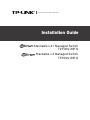
Installation Guide
Stackable L2+ Managed Switch
T2700G-28TQ
Stackable L3 Managed Switch
T3700G-28TQ
COPYRIGHT & TRADEMARKS
Specifications are subject to change without notice.
is a registered trademark of TP-LINK
TECHNOLOGIES CO., LTD. Other brands and product names are trademarks of their respective holders.
No part of the specifications may be reproduced in any form or by any means or used to make any derivative such
as translation, transformation, or adaptation without permission from TP-LINK TECHNOLOGIES CO., LTD. Copyright
© 2015 TP-LINK TECHNOLOGIES CO., LTD. All rights reserved.
http://www.tp-link.com
FCC STATEMENT
This equipment has been tested and found to comply with the limits for a Class A digital device, pursuant to part
15 of the FCC Rules. These limits are designed to provide reasonable protection against harmful interference when
the equipment is operated in a commercial environment. This equipment generates, uses, and can radiate radio
frequency energy and, if not installed and used in accordance with the instruction manual, may cause harmful
interference to radio communications. Operation of this equipment in a residential area is likely to cause harmful
interference in which case the user will be required to correct the interference at his own expense.
This device complies with part 15 of the FCC Rules. Operation is subject to the following two conditions:
1)
This device may not cause harmful interference.
2)
This device must accept any interference received, including interference that may cause undesired operation.
Any changes or modifications not expressly approved by the party responsible for compliance could void the user’s
authority to operate the equipment.
CE Mark Warning
This is a class A product. In a domestic environment, this product may cause radio interference, in which case the
user may be required to take adequate measures.
I
Copyright & Trademarks
Related Document
The User Guide and CLI Reference Guide of the product are provided on the resource
CD.
To obtain the latest product information, please visit the Official Website:
http://www.tp-link.com
About this Installation Guide
This Installation Guide describes the hardware characteristics, installation methods and
the points that should be attended to during installation.
This Installation Guide is structured as follows:
Chapter 1 Introduction. This chapter describes the External Components of the
switch.
Chapter 2 Preparing For Installation. This chapter illustrates the safety precautions
before installing the switch.
Chapter 3 Installation. This chapter illustrates how to install the switch.
Chapter 4 Lightning Protection. This chapter illustrates how to prevent lightning
damage.
Chapter 5 Connection. This chapter illustrates how to do the physical connection of
the switch.
Chapter 6 Configuration. This chapter instructs you to configure the switch via Web
Interface and CLI commands.
Appendix A Troubleshooting.
Appendix B Hardware Specifications.
Related Document
II
Audience
This Installation Guide is for:
Network Engineer
Network Administrator
Conventions
Due to the similarity in structure of TP-LINK Jetstream Stackable Managed Switch
Series, in this Installation Guide we take T3700G-28TQ as an example to illustrate
Chapter 2 Preparing for Installation, Chapter 3 Installation, Chapter 4 Lightening
Protection and Chapter 5 Connection.
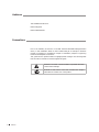
This guide uses the specific formats to highlight special messages. The following table
lists the notice icons that are used throughout this guide.
Remind to be careful. A caution indicates a potential which may
result in device damage.
Remind to take notice. The note contains the helpful
information for a better use of the product.
III
Audience
Contents
Chapter 1 Introduction————————————— 01
1.1 Product Overview..........................................01
1.2Appearance..................................................01
Chapter 2 Preparing For Installation——————— 05
2.1 Package Contents..........................................05
2.2 Safety Precautions.........................................05
2.3 Installation Tools...........................................07
2.4 Installation & Connection Flow.......................07
Chapter 3 Installation—————————————— 09
3.1 Installing the Switch on a Desktop.....................09
3.2 Installing the Switch Into a 19-inch Rack............09
3.3 Installing & Removing the Power Supply Module....10
3.4 Installing & Removing the Interface Card .........11
3.5 Stacking Using Interface Card on Rear Panel .....12
Chapter 4 Lightning Protection————————— 14
4.1 Cabling Reasonably.......................................14
4.2 Connect to Ground........................................16
4.3 Equipotential Bonding....................................17
4.4 Use Lightning Arrester...................................18
Chapter 5 Connection—————————————— 19
5.1 Ethernet Port................................................19
5.2 SFP/SFP+ Port..............................................19
5.3 Console Port.................................................19
5.4 Verify Installation..........................................20
5.5 Power on via Power Supply Module ..............20
5.6 Power on via Redundant Power Supply ..........21
5.7Initialization..................................................22
Chapter 6 Configuration————————————— 23
6.1 Configure the Switch via GUI.........................23
6.2 Configure the Switch Using CLI......................24
Appendix A Troubleshooting——————————— 29
Appendix B Hardware Specifications——————— 30
Contents
IV
Stackable L2+/L3 Managed Switch
Chapter 1 Introduction
1.1 Product Overview
T2700G-28TQ/T3700G-28TQ is TP-LINK’s JetStream Stackable L2+/L3 Managed
Switch, supporting up to 4 SFP+ slots. T2700G-28TQ/T3700G-28TQ is ideal for
large businesses, campuses or SMB networks requiring an outstanding, reliable and
affordable 10 Gigabit solution.
T2700G-28TQ/T3700G-28TQ supports stacking of up to 8 units, thus providing flexible
scalability and protective redundancy for your networks. Moreover, aiming to better
protect your network, T2700G-28TQ/T3700G-28TQ’s main power is removable. With the
help of TP-LINK’s RPS, administrators can easily change its main power if it encounters
some problems without shutting down the switch, thus enabling your network to really
enjoy the benefit of uninterrupted operation.
Supporting advanced features such as OSPF, VRRP, IGMP and PIM DM/SM, T3700G28TQ can fully implement resilient scalable networks, and T2700G-28TQ can be
upgraded with the addition of a layer 3 license to provide these layer 3 routing features
as well.
Note:
Obtain the T2700G-28TQ Layer 3 License T2700G-28TQ-L1000 via the following steps:
1.Buy a license key from a TP-LINK authorized distributor.
2.Go to T2700G-28TQ page on TP-LINK website, use the license key together with the
switch S/N and the MAC address for authentication to download the license T2700G28TQ-L1000.
1.2 Appearance
■■
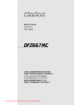
Front Panel
The front panel of T3700G-28TQ is shown as the following figure.
Console Port
LEDs
10/100/1000Mbps RJ45 Port
SFP Port
SFP+ Port
Unit ID LED
Figure 1-1 Front Panel of T3700G-28TQ
Console Port
Designed to connect with the serial port of a computer or terminal for monitoring
and configuring the switch.
01
Introduction
Stackable L2+/L3 Managed Switch
LEDs
LED
Power
System
Status
Indication
On
The switch is powered on
Off
The switch is powered off or power supply is abnormal
Flashing
Power supply is abnormal
Flashing
The switch works properly
On/Off
The switch works improperly
Green
Both the Power Supply Module and the redundant
power supply work properly
Yellow
The Power Supply Module works improperly, but the
redundant power supply works properly
On
RPS
FAN
Master
Module
Off
The switch is not connected to any redundant power
supply
Green
All the fans work properly
Yellow
Not all the fans work properly
On
The switch works as master in the stack system, or
does not join any stack system
Off
The switch works as slave in the stack system
On(green)
An Interface Card is connected to the switch and works
properly
Flashing(yellow)
An Interface Card is connected to the switch, but
works improperly
Off
No Interface Card is connected to the switch
Green
Link/Act
(Port 1-24)
21F-24F
25, 26
Yellow
On
A 1000Mbps device is connected to the corresponding
port, but no activity
Flashing
Data is being transmitted or received
On
A 10/100Mbps device is connected to the corresponding
port, but no activity
Flashing
Data is being transmitted or received
Off
No device is connected to the corresponding port
On
An SFP transceiver is connected to the corresponding
port, and it is connected to a device, but no activity
Flashing
A 1000Mbps device is connected to the corresponding
port and transmitting data
Off
An SFP transceiver is connected to the corresponding
port, but it is not connected to a device, or no SFP
transceiver is connected
On
An SFP+ transceiver/c able is connec ted to the
corresponding port, and it is connected to a 10Gbps
device, but no activity
Flashing
A 10Gbps device is connected to the corresponding
port and transmitting data
Off
An SFP+ transceiver/c able is connec ted to the
corresponding port, but it is not connected to a device,
or no SFP+ transceiver/cable is connected
Introduction
02
Stackable L2+/L3 Managed Switch
LED
Status
Indication
On
An SFP+ transceiver/c able is connec ted to the
corresponding port of the Interface Card, and it is
connected to a 10Gbps device, but no activity
Flashing
A 10Gbps device is connected to the corresponding
port of the Interface Card and transmitting data
Off
1. No Interface Card is connected
2. No SFP+ transceiver/cable is connected to the
installed Interface Card
3. An SFP+ transceiver/cable is connected to the
corresponding port of the Interface Card, but it is
not connected to a device
M1,M2
Port Feature
Model
10/100/1000Mbps
RJ45 Port
Console
Port
1000Mbps
SFP Port
10Gbps SFP+
Port
T2700G-28TQ
24
1
4 (Combo)
4 (2 fixed + 2
optional)
T3700G-28TQ
24
1
4 (Combo)
4 (2 fixed + 2
optional)
10/100/1000Mbps Port
Port 1-24, designed to connect to the device with a bandwidth of 10Mbps, 100Mbps
or 1000Mbps. Each has a corresponding Link/Act LED.
SFP Port
Port 21F-24F, designed to install the SFP transceiver. These four SFP transceiver slots
are shared with the associated RJ45 ports. The associated two ports are referred as
a “Combo” port, which means they cannot be used simultaneously, otherwise only
RJ45 port works. The SFP ports support 1000M SFP module connection only.
SFP+ Port
Port 25-26, designed to install the 10Gbps SFP+ transceiver or SFP+ cables.
T3700G-28TQ also provides an interface card slot on the rear panel to install the
expansion card (TX432 of TP-LINK for example). If TX432 is installed, you get
another two 10Gbps SFP+ ports.
Unit ID LED
Designed to display the stack Unit ID of the switch. For the switch that does
not join any stack system, it displays its default Unit ID. To modify the default
unit number, please logon to the GUI of the switch and go to Stack→Stack
Management→Switch Renumber page.
03
Introduction
Stackable L2+/L3 Managed Switch
■■
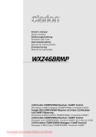
Rear Panel
The rear panel of T3700G-28TQ is shown as the following figure.
Power
PS OK
Fault
PSM150-AC
100-240V~ 50/60Hz 2.5A
Interface Card Slot
Grounding Terminal
RPS Input Connector
Power Supply Module
Figure 1-2 Rear Panel of T3700G-28TQ (1)
Note: The Interface Card Slot and RPS Input Connector are shipped with protective
covers.
Interface Card Slot
Designed to extend the interfaces. You can select a TP-LINK Interface Card (TX432
for example) for your switch if needed. For how to install an Interface Card, please
refer to 3.4 Installing & Removing the Interface Card.
Grounding Terminal
The switch already comes with lightning protection mechanism. You can also ground
the switch through the PE (Protecting Earth) cable of AC cord or with Ground Cable.
For detailed information, please refer to Chapter 4 Lightning Protection.
RPS Input Connector
Designed to connect the RPS (Redundant Power Supply). You can selected an RPS of
TP-LINK (RPS150 for example) for your switch if needed. For how to install an RPS,
please refer to 5.6 Power on via Redundant Power Supply.
Power Supply Module
The AC Power Supply Module PSM150-AC is installled in the switch. The
malfunctioned PSM150-AC can be replaced with a TP-LINK power supply module of
the same model. Its input voltage is 100-240V~ 50/60Hz.
The AC Power Supply Module is fully hot swappable, helping to ensure no system
interruption during installation or replacement. For how to install/remove the Power
Supply Module, please refer to 3.3 Installing & Removing the Power Supply
Module.
Caution: Please use the provided power cord.
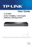
With all the protective covers removed and the Interface Card (TX432 for example)
inserted, the rear panel of T3700G-28TQ is shown as the following figure.
Module
Power
PS OK
Fault
M1
TX432
SFP+
M2
SFP+
CLASS 1 LASER PRODUCT
PSM150-AC
100-240V~ 50/60Hz 2.5A
Figure 1-3 Rear Panel of T3700G-28TQ (2)
Introduction
04
Stackable L2+/L3 Managed Switch
Chapter 2 Preparing For Installation
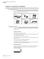
2.1 Package Contents
Make sure that the package contains the following items. If any of the listed items is
damaged or missing, please contact your distributor.
One Switch (One PSM150-AC
included)
O n e Po w e r C o rd a n d o n e
Console Cable
This Installation Guide
One Resource CD
Two mounting brackets and
the fittings
One Power Supply Module
Slot Cover
2.2Safety Precautions
To avoid any device damage and bodily injury caused by improper use, please observe
the following rules.
■■
■■
■■
■■
■■
Safety Precautions
Keep the power off during the installation.
Wear an ESD-preventive wrist strap, and make sure that the wrist strap has a good
skin contact and is well grounded.
Use only the power cord provided with the switch.
Make sure that the supply voltage matches the specifications indicated on the rear
panel of the switch.
■■
Ensure the vent hole is well ventilated and unblocked.
■■
Do not open or remove the cover of the switch.
■■
Before cleaning the device, cut off the power supply. Do not clean it by the waterish
cloth, and never use any other liquid cleaning method.
■■
Site Requirements
To ensure normal operation and long service life of the device, please install it in an
environment that meets the requirements described in the following subsection.
Temperature/Humidity
ȭ
ȭ
05
Preparing For Installation
Stackable L2+/L3 Managed Switch
Please keep a proper temperature and humidity in the equipment room. Too high/low
humidity may lead to bad insulation, electricity leakage, mechanical property changes
and corrosions. Too high temperature may accelerate aging of the insulation materials
and can thus significantly shorten the service life of the device. For normal temperature
and humidity of the device, please check the following table.
Environment
Temperature
Humidity
Operating
0℃ ~ 40℃
10% ~ 90%RH Non-condensing
Storage
-40℃ ~ 70℃
5% ~ 90%RH Non-condensing
Clearness
L5428E
The dust accumulated on the switch can be absorbed by static electricity and result
in poor contact of metal contact points. Some measures have been taken for the
device to prevent static electricity, but too strong static electricity can cause deadly
damage to the electronic elements on the internal circuit board. To avoid the effect of
static electricity on the operation of the switch, please attach much importance to the
following items:
■■
Dust the device regularly, and keep the indoor air clean.
■■
Keep the device well grounded and ensure static electricity has been transferred.
Electromagnetic Interference
Electronic elements including capacitance and inductance on the device can be affected
by external interferences, such as conducted emission by capacitance coupling,
inductance coupling, and impedance coupling. To decrease the interferences, please
make sure to take the following measures:
■■
■■
■■
Use the power supply that can effectively filter interference from the power grid.
eep the device far from high-frequency, strong-current devices, such as radio
K
transmitting station.
Use electromagnetic shielding when necessary.
Lightening Protection
Extremely high voltage currents can be produced instantly when lightning occurs and
the air in the electric discharge path can be instantly heated up to 20,000℃. As this
Preparing For Installation
06
Stackable L2+/L3 Managed Switch
instant current is strong enough to damage electronic devices, more effective lightning
protection measures should be taken.
■■
Ensure the rack and device are well earthed.
■■
Make sure the power socket has a good contact with the ground.
■■
Keep a reasonable cabling system and avoid induced lightning.
■■
Use the signal SPD (Surge Protective Device) when wiring outdoor.
Note: For detailed lightning protection measures, please refer to Chapter 4
Lightning Protection.
Installation Site
When installing the device on a rack or a flat workbench, please note the following
items:
■■
■■
■■
he rack or workbench is flat and stable, and sturdy enough to support the weight of
T
5.5kg at least.
he rack or workbench has a good ventilation system. The equipment room is well
T
ventilated.
he rack is well grounded. Keep the power socket less than 1.5 meters away from the
T
device.
2.3Installation Tools
■■
Phillips screwdriver
■■
ESD-preventive wrist wrap
■■
Cables
Note: These tools are not provided with our product. If needed, please self purchase
them.
2.4Installation & Connection Flow
The switch provides two interfaces to install the swappable Power Supply Module and
Interface Card, and one interface to connect to Redundant Power Supply. The switch
has already been installed with a Power Supply Module PSM150-AC, and you can also
self-purchase the Interface Card/Redundant Power Supply if needed.
07
Preparing For Installation
Stackable L2+/L3 Managed Switch
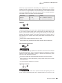
The Installation & Connection flow is shown as the following figure.
Start
Install the switch to the
specified position
Connect to the ground
Install Interface Card?
No
Yes
Install the Interface Card
Verify installation
Power on via Power
Supply Module
Connect to SFP/SFP+
transceivers and cables
Also power on via
RPS?
No
Yes
Connect to RPS
End
Figure 2-1 Installation & Connection Flow
Caution: Make sure the power supply of RPS150 is cut off when connecting or
disconnecting RPS150 and the switch, otherwise both RPS150 and the switch may work
abnormally or even be damaged.
Note: The switch can be powered by the Power Supply Module and Redundant Power
Supply simultaneously or individually. If simultaneously, the Power Supply Module and
Redundant Power Supply together will enable your network to enjoy the benefit of
uninterrupted operation.
Preparing For Installation
08
Stackable L2+/L3 Managed Switch
Chapter 3 Installation
3.1 Installing the Switch on a Desktop
To install the switch on the desktop, please follow the steps below:
1.Set the switch on a flat surface strong enough to support the entire weight of the
device with all fittings.
2.Remove the adhesive backing papers from the rubber feet.
3.Turnover the switch and attach the supplied rubber feet to the recessed areas on
the bottom at each corner of the switch.
Feet
Bottom of the Device
Notch
Figure 3-1 Desktop Installation
3.2Installing the Switch Into a 19-inch Rack
To install the switch in an EIA standard-sized, 19-inch rack, follow the instructions
described below:
1.Check the grounding and stability of the rack.
2.Secure the supplied rack-mounting brackets to each side of the switch with supplied
screws, as illustrated in the following figure.
Rack-mounting Bracket
Screw
Figure 3-2 Bracket Installation
09
Installation
Stackable L2+/L3 Managed Switch
3.After the brackets are attached to the switch, use suitable screws (not provided) to
secure the brackets to the rack, as illustrated in the following figure.
Rack
Figure 3-3 Rack Installation
Caution:
■■
■■
■■
Please set 5~10cm gaps around the device for air circulation.
Please avoid any heavy thing placed on the switch.
Please mount switches in sequence from the bottom to top of the rack and ensure a
certain clearance between switches for the purpose of heat dissipation.
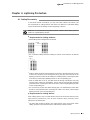
3.3Installing & Removing the Power Supply Module
The Power Supply Module has already been installed in the switch. Operate as the
following steps if you need to replace the Power Supply Module.
■■
Removing the Power Supply Module
1.Wear an ESD-preventive wrist strap, and make sure that it has good skin contact and
is well grounded.
2.Remove the power cord from the power module and the external power supply
system.
3.Use a Phillips screwdriver to loosen the captive screws at both sides of the power
supply module until all spring pressure is released.
4.Pull the handle by one hand towards you along the guide rails, and hold the bottom
of the module by the other hand, until it completely comes out of the switch chassis.
5.In order to better protect the removed power supply module, it is recommended to
package it by an antistatic bag.
6.After removing the PSM150-AC, please install the protective cover as soon as
possible to prevent dust from entering and ensure the normal ventilation in the
switch.
■■
Installing the Power Supply Module
1.Wear an ESD-preventive wrist strap, and make sure that it has good skin contact and
is well grounded.
Installation
10
Stackable L2+/L3 Managed Switch
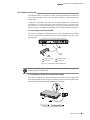
2.If the protective cover has been installed on the power supply module slot of the
switch, use a Phillips screwdriver to loosen the mounting screws of the protective
cover and remove the protective cover, as shown in the following figure.
Figure 3-4 Removing the Protective Cover
3.Grip the handle of the module by one hand, and hold the bottom of the module by
the other hand, as shown in the following figure. Then gently push the module in
along the slot guide rail until the module is flush with the switch.
Note: Do not use too much force in the operation. If resistance is encountered or
positions of the power supply module appear larger deflection in the operation of
installation, you must first remove the module and then reinstall the module.
Switch
Power
PS OK
Fault
AC
PSM150-
Figure 3-5 Installing the Power Supply Module
4.Tighten the captive screws with a Phillips screwdriver to fix the power supply module
in place. If the screws cannot be tighten, probably because the power supply module
is not installed properly due. Please check carefully.
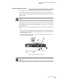
3.4Installing & Removing the Interface Card (Optional)
■■
Installing the Interface Card
1.Wear an ESD-preventive wrist strap, and make sure that it has good skin contact and
is well grounded.
2.Use a Phillips screwdriver to loosen the mounting screws of the protective cover on
the interface card slot of the switch and remove the protective cover, similar to the
procedure shown in Figure 3-4.
11
Installation
Stackable L2+/L3 Managed Switch
3.Hold the captive screws on the front panel of the interface card, and gently push
the interface card in along the slot guide rail until the interface card is flush with the
switch, as shown in the following figure.
Switch
Figure 3-6 Installing the Interface Card
4.Tighten the captive screws with a Phillips screwdriver to fix the interface card in
place.
■■
Removing the Interface Card
1.Wear an ESD-preventive wrist strap, and make sure that it has good skin contact and
is well grounded.
2.Use a Phillips screwdriver to loosen the captive screws at both sides of the interface
card until all spring pressure is released.
3.Pull the interface card towards you along the guide rails, until it completely comes
out of the switch chassis.
4.After removing an interface card, if no new interface card is to be installed, please
install the protective cover as soon as possible to prevent dust from entering and
ensure the normal ventilation in the switch.
Note:
■■
■■
TX432 supports hot plug, so if necessary you can install or remove the interface card
when the switch is operating. However, it is recommended that the power be turned
off during installation.
Do not touch the surface-mounted components directly with your hand while the
switch is in operation.
3.5Stacking Using Interface Card on Rear Panel
You can connect up to 8 switches to form a stack with a single management IP address.
Follow the steps below to connect the switches and configure the stack ports, then the
switches will automatically elect a master unit and establish a stack. Once the stack
is established, you can use any port of any switch in the stack to manage the stack
system.
You can use either the SFP+ ports on the front panel or the Interface Card on the rear
panel to create a stack. These two pairs of stack ports cannot be mixedly used in the
stack connection.
Here we take stacking using Interface Card for example.
1.Install an Interface Card (TX432 for example) into the Interface Card Slot of each
switch, see 3.4 Installing & Removing the Interface Card.
Installation
12
Stackable L2+/L3 Managed Switch
2.Log on to the GUI of each switch, go to Stack→Stack Management→Stack
Config page to enable the stack mode of port M1 and M2 (port 1/1/1 and 1/1/2 on
the GUI). Remember to click Save Config after the configuration.
3.Power off the switches, and then connect a 10G SFP+ cable (TXC432-CU1M/TXC432CU3M of TP-LINK for example) between each pair of Interface Cards among the
switches, thus forming a ring topology as the following figure shows. A ring topology
system provides redundancy and resiliency to the stack.
Module
M2
M1
SFP+
UCT
SFP+
R PROD
S 1 LASE
CLAS
SFP+ cable
TX432
Module
Power
PS OK
Fault
M1
TX432
M2
SFP+
SFP+
CLASS 1 LASER PRODUCT
Module
PSM150-AC
100-240V~ 50/60Hz 2.5A
Power
PS OK
Fault
M1
M2
SFP+
TX432
SFP+
CLASS 1 LASER PRODUCT
Module
PSM150-AC
100-240V~ 50/60Hz 2.5A
Power
PS OK
Fault
M1
TX432
SFP+
M2
SFP+
CLASS 1 LASER PRODUCT
PSM150-AC
100-240V~ 50/60Hz 2.5A
Figure 3-7 Stacking Using Interface Card
4.Power on the switches, then the switches will automatically select a master unit. The
Master LED of the selected switch will be on.
5.You can access to any member of the stack via Web/SSH/Telnet/Console connection,
thus to manage all the switches in the stack.
Caution: In the process of using TP-LINK SFP+ Cables, please never bend them into
a radius of 45mm (1.77 inch) or less, because it may permanently damage the SFP+
Cables.
13
Installation
Stackable L2+/L3 Managed Switch
Chapter 4 Lightning Protection
4.1 Cabling Reasonably
In the actual network environment, you may need cable outdoors and indoors, and
the requirements for cabling outdoors and indoors are different. A reasonable cabling
system can decrease the damage of induced lightning to devices.
Note: It’s not recommended using Ethernet cables outdoors. When cabling outdoors,
please use a signal lightning arrester.
■■
■■
■■
■■
■■
■■
Requirements for Cabling Outdoors
Aerial cabling without safeguard is not allowed.
It’s not allowed cabling down the building to connect network devices in different
floors.
Outdoor cables should be buried and paved to the indoor through basement. A piece
of steel wire should be paved underground along the pipe and connected to the
lightning protection terminal of the building for shielding. Before connecting the cable
to the device, install a signal lightning arrester on the corresponding port.
When an aerial cable is set up, the cable should be through a metal pipe (15m long
at least) before coming into the building. The two ends of this metal pipe should be
grounded. Before connecting the cable to the device, install a signal lightning arrester
on the corresponding port.
It’s not necessary to pave STP cables through pipes. The shielded layer of STP cable
should be well grounded. Before connecting the cable to the device, install a signal
lightning arrester on the corresponding port.
■■
Requirements for Cabling Indoors
When cabling indoors, keep a certain distance away from the devices that may cause
high-frequency interferences, such as down-conductor cable, powerline, power
transformer and electromotor.
■■
The main cable should be paved in the metal raceway of the access shaft. When
cabling, keep the loop area formed by the cable itself as small as possible.
Lightning Protection
14
Stackable L2+/L3 Managed Switch
■■
Requirements for the distance between Ethernet cable and other pipelines are shown
in the table.
Ethernet Cable
Other Pipelines
Min Parallel Net Length Min Parallel-overlapping Net Height
L (mm)
H (mm)
Down-conductor
1000
300
PE
50
20
Service pipe
150
20
Compressed air pipe
150
20
Thermal pipe (not wrapped) 500
500
Thermal pipe (wrapped)
300
300
Gas pipe
300
20
The two diagrams below demonstrate parallel net length and parallel-overlapping net
height.
Note: The above minimum net length/height is required when metal raceway is not
used. If any requirements cannot be met, you can add a steel tube or metal raceway
for shielding.
■■
Requirements for the distance between Ethernet cable and high-power electric
devices are in following tables.
Cable
<2kVA
powerline
2~5kVA
powerline
>5kVA
powerline
15
Lightning Protection
Pave Way
Min Parallel
Length (mm)
Parallel cabling
130
One is in the grounded metal raceway or metal pipe
70
The both are in the grounded metal raceway or metal pipe
10
Parallel cabling
300
One is in the grounded metal raceway or metal pipe
150
The both are in the grounded metal raceway or metal pipe
80
Parallel cabling
600
One is in the grounded metal raceway or metal pipe
300
The both are in the grounded metal raceway or metal pipe
150
Device
Min Distance (m)
Switch case
1.00
Transformer room
2.00
Elevator tower
2.00
Air-conditioner room
2.00
Stackable L2+/L3 Managed Switch
4.2Connect to Ground
Connecting the device to ground is to quickly release the lightning over-voltage and
over-current of the device, which is also a necessary measure to protect the body from
electric shock.
In different environments, the device may be grounded differently. The following
will instruct you to connect the device to the ground in two ways, connecting to the
grounding bar or connecting to the ground via the power cord. Please connect the
device to ground in the optimum way according to your specific operation environment.
■■
Connecting to the Grounding Bar
If the device is installed in the Equipment Room, where a grounding bar is available,
you are recommended to connect the device to the Grounding Bar as shown in the
following figure.
Module
Power
PS OK
Fault
M1
M2
SFP+
TX432
SFP+
CLASS 1 LASER PRODUCT
PSM150-AC
100-240V~ 50/60Hz 2.5A
Switch (Rear Panel)
Grounding Terminal
Ground Cable
Grounding Bar
Figure 4-1 Connecting to the Grounding Bar
Note: The grounding bar and ground cable are not provided with our product. If
needed, please self purchase them.
■■
Connecting to the Ground via the Power Supply
If the device is installed in the normal environment, the device can be grounded via the
PE (Protecting Earth) cable of the AC power supply as shown in the following figure (take
powered by the Power Supply Module PSM150-AC for example).
Modu
le
TX43
2
M1
SFP+
M2
SFP+
CLASS
1 LASER
PRODU
CT
Power
PS OK
Fault
PSM1
50-AC
100-240
V~ 50/60Hz
2.5A
Figure 4-2 Connecting to the Ground
Lightning Protection
16
Stackable L2+/L3 Managed Switch
Note:
■■
■■
The figure is to illustrate the application and principle. The power cord you get from
the package and the socket in your situation will comply with the regulation in your
country, so they may differ from the figure above.
If you intend to connect the device to the ground via the PE (Protecting Earth) cable
of AC power cord, please make sure the PE (Protecting Earth) cable in the electrical
outlet is well grounded in advance.
4.3Equipotential Bonding
Equipotential Bonding is the practice of intentionally electrically connecting all earthed
systems to the same grounding grid or connecting the grounding grids of all the
earthed systems together through the ground or overground metal so as to create
an earthed equipotential zone. When lightning occurs, the high voltage produced by
lightning current in all systems will meanwhile exist in their ground cables, and thus
all ground cables have the same electrical potential and basically eliminate the electric
strikes between the systems.
The figure bellow illustrates how to practice equipotential bonding in a network.
Power
PS OK
Fault
PSM1
50-AC
100-240
V~ 50/60Hz
2.5A
Power
PS OK
Fault
PSM1
50-AC
100-240
V~ 50/60Hz
2.5A
Power
PS OK
Fault
PSM1
50-AC
100-240
V~ 50/60Hz
2.5A
Grounding Terminal
Equipotential Bonding Cable
Ground Cable
Grounding Bar
Figure 4-3 Equipotential Bonding
When equipotential bonding, please note that the cable should be copper wrapped Kelly
with its area being 6mm2 at least. The shorter cable the better, and use a grounding
bar to establish an equipotential bonding point.
Note: The equipotential bonding cable is not provided with our product. If needed,
please self purchase it.
17
Lightning Protection
Stackable L2+/L3 Managed Switch
4.4Use Lightning Arrester
Power lightning arrester and signal lightning arrester are used for lighting protection.
Power lightning arrester is used for limiting the voltage surge due to a lightning. If an
outdoor AC power cord should be directly connected to the device, please use a power
lightning arrester.
Note: Power lightning arrester is not provided with our product. If needed, please self
purchase it.
Signal lightning arrester is used to protect RJ45 ports of the device from lightning.
When cabling outdoors, please install a signal lightning arrester before connecting the
cable to the device.
When purchasing or using a signal lightning arrester, please observe the following
rules:
■■
■■
The port rate of the signal lightning arrester should match the rate of the desired port
on the device. If it is not matched, this signal lighting arrester will not work. Purchase
a standard lightning arrester.
Install signal lightning arrester near the protected device and connect it to the
ground via a shorter ground cable.
Grounding Terminal
Equipotential Bonding Cable
Signal Lightning Arrester
Device
Ethernet Cable
Figure 4-4 Lightning Arrester Connection
Note: Signal lightning arrester is not provided with our product. If needed, please self
purchase it.
Lightning Protection
18
Stackable L2+/L3 Managed Switch
Chapter 5 Connection
5.1 Ethernet Port
Connect the Ethernet ports of the switch to the network devices by RJ45 cable as the
following figure shown.
RJ45 Port
RJ45 Cable
Figure 5-1 Connecting the RJ45 Port
5.2SFP/SFP+ Port
Connect an SFP transceiver to the SFP port, or connect an SFP+ transceiver/cable to
the SFP+ port. For the switch, if an RJ45 port which is combo with SFP port has a valid
link, the associated SFP port will be disabled and cannot be used.
The following takes SFP Transceiver installation as an example.
SFP Port
SFP Transceiver
Figure 5-2 Inserting the SFP Transceiver
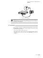
5.3Console Port
CLI (Command Line Interface) enables you to manage the switch, thus you can load
the CLI after connecting the PCs or Terminals to the console port on the switch via the
provided cable.
19
Connection
Stackable L2+/L3 Managed Switch
Connect the console port of the device with your computer by the console cable as the
following figure shown.
Figure 5-3 Connecting the Console Port
You can also manage the device through the console port, for details please refer to the
CLI Reference Guide on the resource CD.
Note:
■■
■■
■■
The console port is the first port on the left of the front panel.
Please keep the device power off when plugging the console cable.
Do not connect the console port with other ports by RJ45 cable.
5.4Verify Installation
After completing the installation, please verify the following items:
■■
■■
here are 5~10cm of clearance around the sides of the device for ventilation and the
T
air flow is adequate.
The voltage of the power supply meets the requirement of the input voltage of the
device.
■■
The power socket, device and rack are well grounded.
■■
The device is correctly connected to other network devices.
5.5Power on via Power Supply Module
After the Power Supply Module (PSM150-AC for example) is installed on the switch,
please plug the female connector of the provided power cord into the power socket of
the device, and the male connector into a power outlet as the following figure shows.
Connection
20
Stackable L2+/L3 Managed Switch
Power
PS OK
Fault
AC
PSM150-
Figure 5-4 Power on via PSM150-AC
Note: The figure is to illustrate the application and principle. The power cord you get
from the package and the socket in your situation will comply with the regulation in
your country, so they may differ from the figure above.
5.6Power on via Redundant Power Supply (Optional)
Follow the steps below to connect the Redundant Power Supply (RPS150 for example)
to T3700G-28TQ.
1.Confirm that the power supply of the RPS150 is cut off.
2.Remove the protective covers covering the redundant power socket of RPS150 and
the switch, similar to the procedure shown in Figure 2-4.
3.Connect the RPS150 and the switch with DC power cord, as illustrated in Figure 5-5.
One end of the DC power cord is marked by the letters “TOP” and the other end has
a positioning card attached to it. Plug the end with the letters “TOP” into the input
socket of the switch with “TOP” facing up and the other end with positioning card
into the DC output socket of the RPS150 with the positioning card facing up.
Modu
le
TX43
2
M1
SFP+
M2
SFP+
CLASS
1 LASER
PROD
UCT
Power
PS OK
Fault
PSM
150-AC
TOP
100-24
0V~ 50/60H
z 2.5A
3
4
Positioning Card
RPS150
3
Switch
4
One connector with letters “TOP”
Figure 5-5 Power on via RPS150
4.Connect the AC input socket of RPS150 and the power socket with the power cord
provided with RPS150, as shown in Figure 5-6.
21
Connection
Stackable L2+/L3 Managed Switch
Figure 5-6 Power on RPS150
Caution: Make sure the power supply of RPS150 is cut off when connecting or
disconnecting RPS150 and the switch, otherwise both RPS150 and the switch may work
abnormally or even be damaged.
5.7Initialization
After the device is powered on, it begins the Power-On Self-Test. A series of tests
run automatically to ensure the device functions properly. During this time, its LED
indicators will respond as follows:
■■
■■
The Power LED indicator will light on all the time.
After keeping off for several seconds, the rest of the LED indicators will flash
momentarily, and then work as the table in 1.2 Appearance shows after the
initialization.
Connection
22
Stackable L2+/L3 Managed Switch
Chapter 6 Configuration
6.1 Configure the Switch via GUI
Note: To log on to the GUI of the switch, the IP address of your PC should be set in
the same subnet addresses of the switch. The IP address is 192.168.0.x ("x" is any
number from 2 to 254), Subnet Mask is 255.255.255.0.
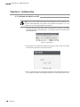
1.To access the GUI of the switch, open a web browser and type in the default
management address http://192.168.0.1 in the address field of the browser, then
press the Enter key.
Figure 6-1 Web Browser
2.Enter admin for the default User Name and Password, both in lower case letters.
Then click the Login button or press the Enter key.
Figure 6-2 Login
3.After a successful login, the main page will appear as the following figure, and you
can configure the function by clicking the setup menu on the left side of the screen.
23
Configuration
Stackable L2+/L3 Managed Switch
Figure 6-3 Main Page of the Switch
6.2Configure the Switch Using CLI
You can log on to the switch and access the CLI by the following two methods:
■■
■■
Log on to the switch by the console port on the switch.
Log on to the switch remotely by a Telnet or SSH connection through an Ethernet
port.
■■
Logon by a Console Port
To log on to the switch by the console port on the switch, please take the following
steps:
1.Connect the PCs or Terminals to the console port on the switch by a provided cable.
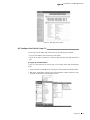
2.Click Start→All Programs→Accessories→Communications→Hyper Terminal to open
the Hyper Terminal as the following figure shown.
Figure 6-4 Open Hyper Terminal
Configuration
24
Stackable L2+/L3 Managed Switch
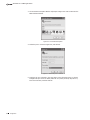
3.The Connection Description Window will prompt as Figure 6-5. Enter a name into the
Name field and click OK.
Figure 6-5 Connection Description
4.Select the port to connect in Figure 6-6, and click OK.
Figure 6-6 Select the port to connect
5.Configure the port selected in the step above as the following Figure 6-7 shown.
Configure Bits per second as 38400, Data bits as 8, Parity as None, Stop bits as 1,
Flow control as None, and then click OK.
25
Configuration
Stackable L2+/L3 Managed Switch
Figure 6-7 Port Settings
6.Type in the User name and Password in the Hyper Terminal window, the factory
default value for both of them is admin. The DOS prompt ”T3700G-28TQ>” will
appear after pressing the Enter button as Figure 6-8 shown. It indicates that you can
use the CLI now.
Figure 6-8 Log in the switch
■■
Logon by Telnet
To log on to the switch by a Telnet connection, please take the following steps:
1.Firstly CLI commands about configuring Telnet login mode, login authentication
information and Privileged EXEC Mode password should be configured through
Console connection. For more details please refer to the CLI Reference Guide on the
resource CD. Here we take login local mode as an example.
2.Make sure the switch and the PC are in the same LAN.
Configuration
26
Stackable L2+/L3 Managed Switch
3.Click Start→Run to open the Run window.
Figure 6-9 Open the Run window
4.Type in cmd in the prompt Run window as Figure 6-10 and click OK.
Figure 6-10 Run Window
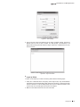
5.Type in telnet 192.168.0.1 in the command prompt shown as Figure 6-11, and press
the Enter button.
Figure 6-11 Connecting to the switch
27
Configuration
Stackable L2+/L3 Managed Switch
6.Type in the User name and Password (the factory default value for both of them is
admin) and press the Enter button, then you can use the CLI now, which is shown as
Figure 6-12.
Figure 6-12 Log in the switch
For detailed CLI configuration instructions, please refer to the CLI Reference Guide on
the resource CD.
Configuration
28
Stackable L2+/L3 Managed Switch
Appendix A Troubleshooting
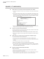
Q1.
What could I do if I forgot the username and password of the switch?
1. Connect the console port of the PC to the console port of the switch and open hyper
terminal.
2.Power off and restart the switch. When you are prompted that “Press CTRL-B to enter
the bootUtil” in the hyper terminal, please press CTRL-B key to enter into bootUtil menu
shown as the following figure. (Please note that there is an extra command for T2700G28TQ to delete the license file)
3. Enter the number 2 to reset the system. The system will be reset to the factory default
settings, and the default login user name and password are both admin.
Q2.
Why does the Power LED work abnormally?
The Power LED should be lit up when the power system works normally. If the Power LED
worked abnormally, please take the following steps:
1.Make sure that the power cable is connected properly, and the power contact is normal.
2.Make sure the voltage of the power supply meets the requirement of the input voltage of
the switch.
Q3.
What could I do if I could not access the web-based configuration page?
You are recommended to check the following items:
1.Check every port LED on the switch and make sure the cable is installed properly.
2.Try another port on the switch and make sure the cable meets the requirement and works
normally.
3.Turn off the power. After a while, turn on the power again.
4.Make sure the IP address of your PC is set within the subnet of the switch.
5.If you still cannot access the configuration page, please restore the switch to its factory
defaults. Then the IP address should be set as 192.168.0.x ("x" is any number from 2 to
254) and Subnet Mask as 255.255.255.0.
Q4.
Why does the hyper terminal display abnormally?
Please check as follows:
1.Make sure the power supply is normal and the console cable is properly connected.
2.Check if the console cable is the right type.
3.Ensure the parameters of the hyper terminal are correct: configure Bits per second as
38400, Data bits as 8, Parity as None, Stop bits as 1, and Flow control as None.
29
Troubleshooting
Stackable L2+/L3 Managed Switch
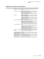
Appendix B Hardware Specifications
Item
Content
IEEE 802.3 10Base-T Ethernet
IEEE 802.3u 100Base-TX/100Base-FX
IEEE 802.3ab 1000Base-T
Standards
IEEE 802.3z 1000Base-X
IEEE 802.3ae 10GBASE-SR
IEEE 802.3ae 10GBASE-LR
IEEE 802.3x Flow Control
10Base-T: UTP/STP of Cat. 3 or above
100Base-TX: UTP/STP of Cat. 5 or above
100Base-FX: MMF or SMF SFP Transceiver
Transmission Medium
1000Base-T: 4-pair UTP (≤100m) of Cat. 5e and Cat. 6 or
above
1000Base-X: MMF or SMF SFP Transceiver
10GBASE-SR: MMF SFP+ Transceiver
10GBASE-LR: SMF SFP+ Transceiver
LEDs
Power, System, RPS, FAN, Master, Module, Link/Act,
21F-24F, 25, 26, M1, M2, Unit ID LED
Operating Temperature 0℃~40℃
Storage Temperature
-40℃~70℃
Operating Humidity
10%~90%RH Non-condensing
Storage Humidity
5%~90%RH Non-condensing
Hardware Specifications
30
Website: http://www.tp-link.com
Tel: +86 755 26504400
E-mail: [email protected]
7106505117 REV1.2.0