1
CONTENTS
CONTENTS ..................................................................................................................................................... A - 1
FURTHER READING REFERENCE LIST........................................................................................................A - 3
CHAPTER 1
INTRODUCTION
1 - 1 to 1 - 4
1.1
Database Overview ......................................................................................................................... 1 - 1
1.2
MES Interface Module Overview ..................................................................................................... 1 - 3
CHAPTER 2
EXAMPLE SYSTEM OUTLINE
CHAPTER 3
REQUIRED EQUIPMENT FOR START-UP
3 - 1 to 3 - 2
CHAPTER 4
EQUIPMENT SETUP
4 - 1 to 4 - 2
CHAPTER 5
SOFTWARE INSTALLATION
5 - 1 to 5 - 6
5.1
2-1
Installation........................................................................................................................................ 5 - 1
CHAPTER 6
CREATING A DATABASE TABLE
6 - 1 to 6 - 6
6.1
General Description ......................................................................................................................... 6 - 1
6.2
OrderTable Creation ........................................................................................................................ 6 - 1
6.3
“History” Table Creation................................................................................................................... 6 - 5
CHAPTER 7
ODBC SETTING
CHAPTER 8
MES INTERFACE CONFIGURATION
7 - 1 to 7 - 3
8 - 1 to 8 - 13
8.1
General Description ......................................................................................................................... 8 - 1
8.2
Specifying Parameters..................................................................................................................... 8 - 3
8.3
Operational Check ......................................................................................................................... 8 - 12
8.3.1
8.3.2
8.3.3
General Description................................................................................................................ 8 - 12
Writing Parameters onto QJ71MES96 Module....................................................................... 8 - 12
Checking Data Written into DB Table..................................................................................... 8 - 13
CHAPTER 9
9.1
FAQs
9 - 1 to 9 - 12
Troubleshooting by symptom........................................................................................................... 9 - 1
9.1.1
9.1.2
When using MES Interface Function Configuration Tool.......................................................... 9 - 1
When using DB Connection Service Setting Tool .................................................................... 9 - 6
A-1
9.1.3
When operating the MES interface module .............................................................................. 9 - 7
CHAPTER 10
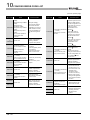
CONCISE ERROR CODE LIST
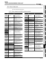
10 - 1 to 10 - 21
10.1
Viewing MES Interface Module Error Codes ................................................................................. 10 - 1
10.2
Viewing Server Computer Error Codes ......................................................................................... 10 - 2
10.2.1
10.3
Log Format ............................................................................................................................. 10 - 3
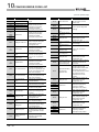
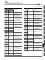
Error Code List............................................................................................................................... 10 - 9
10.3.1
10.3.2
10.3.3
Error codes for the MES interface module.............................................................................. 10 - 9
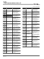
Error codes of DB Connection Service ................................................................................. 10 - 15
Error codes returned in XML response messages ............................................................... 10 - 21
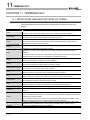
CHAPTER 11
TERMINOLOGY
11 - 1 to 11 - 4
11.1
DEFINITIONS AND DESCRIPTIONS OF TERMS ........................................................................ 11 - 1
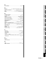
INDEX
Index - 1 to Index - 2
A-2
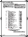
FURTHER READING REFERENCE LIST
The following manuals are also related to this product.
If necessary, order them by quoting the details in the list below.
Manual Name
MES Interface Module User's Manual
MES Interface Module User's Manual (Hardware)
QCPU User's Manual (Hardware Design, Maintenance and Inspection)
QCPU User's Manual (Function Explanation,Program Fundamentals)
GX Developer Version 8 Operating Manual
Manual Number
(Model Code)
SH-080644ENG
(13JR95)
IB-0800354
(13JY02)
SH-080483ENG
(13JR73)
SH-080484ENG
(13JR74)
SH-080373E
(13JU41)
A -3
1
INTRODUCTION
CHAPTER 1 INTRODUCTION
The MES interface enables simple, highly reliable data connectivity between automated
machinery and manufacturing-related computing applications, such as Manufacturing
Execution (MES) and Production Control (PCS), These applications depend on correct
data collection and timely delivery. Compared to conventional connectivity implemented
using gateway computers, direct database connectivity implemented using the MES
Interface will decrease system complexity, improve reliability and eliminate data loss,
resulting in better agility, less maintenance and reduces total cost of ownership (TCO).
This guide aims to provide an introductory guide to setting up the MES Interface Module.
The guide is broken down into an example system, setup, and maintenance sections. For
further reading, please refer to the associated users and hardware manuals provided by
Mitsubishi Electric.
1.1 Database Overview
This section provides general information on databases that the MES Interface uses as a
source or destination for information exchanged with MELSEC controllers.
For this example, a database is defined as software which provides a virtual filing system
for storing groups of related data. It also provides a set of commands that enable access,
editing and manipulation of the stored data. The following are some examples of practical
functions that may occur in a database.
• During processing of a set of data items, an error occurs. In response, the user
might apply a rollback command that restores the data to its original state.
• While certain stored data items are being retrieved in one process, new data arrive
that need to be stored in a second process. The database should handle
completion of both actions without conflict or user intervention.
• A researcher desires to retrieve a specific set of 15 data items that was originally
stored in the database on July 15th at 2:30 AM 5 years ago. The user will create a
“query” or command structure that the database understands as a request for data
retrieval. The database will return the specified information when the query is
executed.
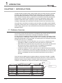
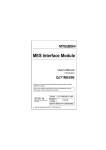
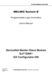
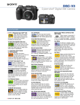
There are various database types including relational, hierarchical, and XML. The MES
Interface operates with relational databases provided by Microsoft or Oracle. Relational
databases organize data into tables consisting of fields (columns) and records (rows). The
contents in one database can range from one table to many thousands.
Field
1-1
Produect name
Number of modules
scheduled for manufacture
No. of modules
manufactured
M7000
300
120
J581-583
500
500
EH10
30
30
DHC8
10
0
Record
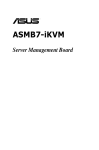
INTRODUCTION
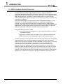
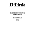
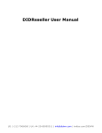
Initial Table Structure
Actual
M7000
300
120
J581-583
500
500
(1) Add a new record to the table that has part number, production schedule and
production actual fields (Insert command executed via the production
scheduling software)
Part
Production
Production
Part
Production
Production
Number
Plan
Actual
Number
Plan
Actual
M7000
300
120
J581-583
500
500
EXAMPLE
SYSTEM OUTLINE
4
EQUIPMENT
SETUP
Production
Plan
Inserting data
M7000
300
120
J581-583
500
500
EH10
30
0
5
SOFTWARE
INSTALLATION
Production
3
6
CREATING A
DATABASE TABLE
Part
Number
2
REQUIRED
EQUIPMENT FOR
START-UP
All common databases implement a standardized command format called SQL (Structured
Query Language). SQL defines each command action a user can apply to operate the
various database functions and the syntax for the command and response messages
paragraph change.
The MES Interface implements certain of these commands. For Acquiring data stored in a
record one uses a “Select” command. For placing data in a record one uses the “Insert”
command. For placing modified data in existing records one uses the “Update” command.
Of many SQL commands available, these three cover direct data exchange between
controllers and databases. Creation of tables, deletion of records and all other database
operations must be implemented outside the MES Interface.
INTRODUCTION
1
Part
Production
Production
Part
Production
Production
8
Number
Plan
Actual
Number
Plan
Actual
MES INTERFACE
CONFIGURATION
ODBC SETTING
7
(2) After execution, add the production actual count to the record (Update
command executed by the MES Interface - moves production count from the
controller to the database)
120
500
EH10
30
0
Updating data
M7000
300
120
J581-583
500
500
EH10
30
12
9
Final Table Structure
FAQs
300
500
10
CONCISE ERROR
CODE LIST
M7000
J581-583
11
TERMINOLOGY
1
Index
1-2
1
INTRODUCTION
1.2 MES Interface Module Overview
The MES Interface provides a highly reliable and easy to implement method for
exchanging data between MELSEC Q controllers or GOTs and common “industrial quality”
databases. Most Manufacturing Execution Software Applications use a database to source
data and deposit results. The product is named "MES Interface", because it greatly
improves MES implementation and operation by providing a high quality, high function link
to the factory equipment.
Setup of the MES functions is made using PC-based configuration software. For most
applications, no computer language programming or control logic programming is
required. The person making setup need not know SQL language or XML language,
because setup is made in a menu driven format and deeper technical aspects are handled
automatically. The idea is that standard engineering or IS staff can easily handle initial
setup and subsequent modification of the MES Interface configuration.
The general setup procedure is simple.
1) Associate (map) controller data devices to the appropriate fields or records in
the database table(s)
2) Set trigger conditions under which data are to be collected and transferred
3) Build transactions associating triggers with the specific data and action
The MES Interface provides enhanced functions beyond simple data transfer that provide
significant benefits. Store and forward buffering of transactions (when the database
connection is lost) supports zero data loss and guaranteed information delivery. One MES
Interface can transact data with up to 32 database connections and it can route
communications to remote MELSEC systems via CC-Link IE, MELSECNET 10/H,
Ethernet, and CC Link, including support for legacy controller lines. Communications
between the MES Interface and the host computer system occur in a secure, encrypted
format and the messages exist in XML format, which is well suited to passage through
common IT infrastructure devices such as firewalls, routers and switches. Automatic time
adjustment to an SNTP server keeps time stamps and database sequencing accurate.
1-3
1
INTRODUCTION
INTRODUCTION
1
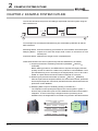
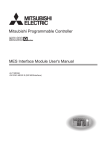
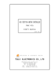
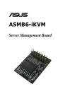
MES interface basic system configuration
The overall system configuration when using the MES Interface module is shown below.
2
EXAMPLE
SYSTEM OUTLINE
Database
SNTP server
personal computer *1*2*4
Oracle ,SQL Server,
Access, etc. (products
from other companies)
See Chapter 6.
Server personal computer
REQUIRED
EQUIPMENT FOR
START-UP
3
DB connection service
DB connection service
setting tool
Ethernet
EQUIPMENT
SETUP
4
MES interface module
See Chapter 8.
5
SOFTWARE
INSTALLATION
Compact Flash card
MES interface
configuration
tool
Personal computer used
for operational settings*1
6
CREATING A
DATABASE TABLE
CC-Link IE, etc.
:Functions provided by the MX MES Interface
*1. The SNTP server personal computer and the personal computer used for operational settings can
be used with the server personal computer.
*2. MES interface module time is required when SNTP server personal computer time is used.
*3. In this guide, the DB connection service setting is set to the default to shorten explanations.
*4. This is not used in the system configuration examples given in this guide.
8
MES INTERFACE
CONFIGURATION
Q/QnA/ACPU*4
ODBC SETTING
7
FAQs
9
CONCISE ERROR
CODE LIST
10
11
TERMINOLOGY
Q/QnA/ACPU*4
Index
1-4
2
EXAMPLE SYSTEM OUTLINE
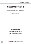
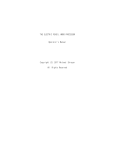
CHAPTER 2 EXAMPLE SYSTEM OUTLINE
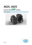
This section describes the process of building a simple data collection system using the
MES Interface unit.
Machining
Inspection
Stamping
Our example uses a metal parts manufacturing line automated by MELSEC Q and the
MES Interfaces.
Machining Station: Executes machining processes that convert blanks into finished parts.
Stamping Station: Imprints a lot code and unique serial number on the surface of each
finished part.
Inspection Station: Measures the weight of each completed parts.
Interactions between the control system and production database are as follows.
1) Acquiring Production Scheduling Information (Database MES I/F
Controller)
Before starting production, the MES Interface acquires the target production
quantity and lot ID code from a table in the production control database. Then
part manufacturing occurs according to the target quantity. The Lot ID code is
added as a prefix before the serial number is stamped on each part.
2) Delivering As-produced Information (Controller MES I/F Database)
After each part exits the inspection station, the actual serial number, production
time and part weight are collected by the MES Interface and transferred to the
production control database.
3) Modifying Data to Improve Usability (Scaling in the MES I/F)
The inspection scale reports part weight to the control system in grams +
decimal, but a production report from the database information should read in
milligrams. To avoid control logic changes and extra processing at the
database level, the weight data is converted to mg format in the MES interface.
Production Target = 35 pieces
Lot Code = US
MELSEC Q with
MES Interface unit
2-1
US2001 10:00:00
0.501mg
US2002 10:00:10
0.495mg
US2035 10:05:50
0.512mg
DB
Production Control
3
REQUIRED EQUIPMENT FOR START-UP
INTRODUCTION
1
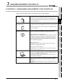
CHAPTER 3 REQUIRED EQUIPMENT FOR START-UP
QJ71MES96
The MES interface module establishes linkages between device data of a
programmable controller (production equipment) and a database of an
information system (MES: Manufacturing Execution System), without using
a communication gateway.
Compact Flash card
GT05-MEM-128MC
The MES interface module is equipped with and uses one Compact Flash
3
REQUIRED
EQUIPMENT FOR
START-UP
MES interface module,
EXAMPLE SYSTEM OUTLINE
2
Before creating a sample system, the following items must be prepared.
4
Module User's Manual.
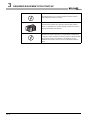
Configuration software,MX
Only specifying necessary data allows data communications (SQL texts)
MESInterface SW1DNC-MESIF-E
without any programming.This software includes the following tools:
• MES interface function configuration tool
required for the MES interface function of the MES interface module.
6
In addition to the settings, checking the operating status or operation
CREATING A
DATABASE TABLE
Software that is run on a configuration computer and performs settings
logs and stopping/restarting the MES interface function operation are
also available with this software.
• DB connection service
7
ODBC SETTING
Software that is run on a server computer and is used for linking a
• DB connection service setting tool
Software that is run on a server computer and is used to change the
settings of “DB connection service”.
The computer is used as a server computer and a configuration computer.
In this guide, Microsoft
Windows
XP Professional Operating System is
used as the basic software (OS) in explanations.
For hardware requirements of the computer to be used, refer to “MES
8
MES INTERFACE
CONFIGURATION
database to the MES interface module.
Computer
5
SOFTWARE
INSTALLATION
For more on usable Compact Flash cards, please refer to MES Interface
EQUIPMENT
SETUP
card.
9
Interface Module User's Manual”.
100BASE-TX.
Use straight cables when using a hub, or use a crossing cable when not
using a hub.
10
CONCISE ERROR
CODE LIST
Cables must be compliant with the standard of IEEE802.3 10BASE-T/
FAQs
Used to connect the computer to the MES interface module, QJ71MES96.
11
TERMINOLOGY
Twisted pair cables and a hub
Index
3-1
3
REQUIRED EQUIPMENT FOR START-UP
Microsoft Access 2003
Basic software that is run on a server computer and used to create a
sample database provided in this guide.
Programmable controller CPU
A programmable controller CPU system that uses the MES interface
module. For applicable CPU modules, quantity, and base units, refer to
“MES Interface Module User's Manual”.
GX Developer
An integrated programming tool for performing design, debugging, and
maintenance of sequence programs for programmable controller CPUs.
By using this, sequence program monitoring, program or data modification
during program execution, and ON/OFF of inputs/outputs are also
available.For the operation method, refer to “GX Developer Operating
Manual”.
3-2
4
EQUIPMENT SETUP
INTRODUCTION
1
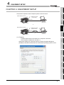
CHAPTER 4 EQUIPMENT SETUP
2
MES interface module
EXAMPLE SYSTEM OUTLINE
Components required to build a sample system are shown below:
Twisted pair cable
(cross cable)
3
REQUIRED
EQUIPMENT FOR
START-UP
Ethernet
Computer
192.168.3.1
192.168.3.3
or
EQUIPMENT
SETUP
MES interface module
4
Twisted pair cable
(straight cable)
Ethernet
5
192.168.3.3
Computer
192.168.3.1
SOFTWARE
INSTALLATION
Hub
(1) Computer
CREATING A
DATABASE TABLE
6
• Install the Microsoft Access 2003 on the computer concerned.
• Set computer IP address to 192.168.3.1.
Change this setting in the Internet Protocol (TCP/IP) Properties dialog box.
(Example) If the Microsoft Windows XP Professional operating system is used,
ODBC SETTING
7
MES INTERFACE
CONFIGURATION
8
FAQs
9
CONCISE ERROR
CODE LIST
10
TERMINOLOGY
11
Index
4-1
4
EQUIPMENT SETUP
(2) MES Interface Module (QJ71MES96)
• Mount the MES interface module in a slot other than the base module CPU slot.
• Mount the Compact Flash card in the MES interface module Compact Flash card
mount slot.
• The Compact Flash card is formatted using the format function of the information
linking function configuration tool.
Do not format the Compact Flash card in Windows . In the event of accidentally
formatting the Compact Flash card in Windows , reformat following the
instructions in the Compact Flash card manual.
(3) Sequencer CPU
• Write the following sequence program which simulates a metal part
manufacturing line, into the CPU.
Manufacturing code setting
Stop operation when pecified number of modules manufactured is reached
Generate a signal at intervals of 10 seconds.
Generate a serial number.
Take weight measurements(emulation).
4-2
5
SOFTWARE INSTALLATION
INTRODUCTION
1
In this guide, the method when using Microsoft Windows XP Professional Operating
System is explained. When using other basic software (OS), refer to the MES Interface
Module User's Manual.
5.1 Installation
2
EXAMPLE SYSTEM OUTLINE
This section explains how to install MX MESInterface function configuration software in
each operating environment.
3
REQUIRED
EQUIPMENT FOR
START-UP
CHAPTER 5 SOFTWARE INSTALLATION
4
EQUIPMENT
SETUP
This section explains how to install MX MESInterface.
(1) MX MESInterface installation procedure
5
SOFTWARE
INSTALLATION
Installation start
Execute SET UP.exe.
6
CREATING A
DATABASE TABLE
Select the component to
be installed.
Exit
Which software is
to be installed?
ODBC SETTING
MES Interface
Function
Configuration Tool
Enter user information.
Enter the product ID.
Enter the product ID.
Select the installation
destination.
Select the installation
destination.
8
9
FAQs
Enter user information.
MES INTERFACE
CONFIGURATION
DB Connection Service
and Setting Tool
7
10
CONCISE ERROR
CODE LIST
Installation
If a confirmation message for overwriting DLL files is displayed at installation, click
TERMINOLOGY
11
Installation complete
Index
the Yes button and overwrite the DLL files.
Not overwriting the DLLs may fail to execute MX MESInterface correctly.
5-1
5
SOFTWARE INSTALLATION
(2) MX MESInterface installation
For system configurations, refer to the following:
(1) When installing MX MESInterface, log on as a user with Administrator
authority.
(2) Before installing MX MESInterface, close any other applications running on
Windows .
(3) Updates for the OS or software from other companies, such as Windows
Update or java applets, automatically restart the computer and in some
cases, the installer will not operate normally.
Install the software after changing the settings so that updates do not
automatically restart the computer.
(Start)
1
(To the next page)
5-2
Start Windows Explorer, then click the drive in
which the CD-ROM is loaded.
Double click “SETUP.exe”.
To display Windows Explorer, right click [Start],
then select [Explore].
SOFTWARE INSTALLATION
INTRODUCTION
1
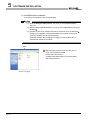
2 The dialog box for selecting the component to be
installed is displayed.
Select the component to be installed with the
radio button, then click the Install button.
2
EXAMPLE SYSTEM OUTLINE
(From the previous page)
REQUIRED
EQUIPMENT FOR
START-UP
3
4
EQUIPMENT
SETUP
1 If the left message appears, click the Cancel
button and after uninstalling MX MESInterface,
install this product.
CREATING A
DATABASE TABLE
7
8
MES INTERFACE
CONFIGURATION
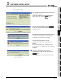
3 If the left message appears, execute
\EnvMEL\Setup.exe in the CD-ROM for this
product.
4 After executing Setup.exe, install this product.
5 If the product is not installed correctly, restart the
computer.
6
ODBC SETTING
2 If the left message appears, install this product on
a computer to which the basic software (OS)
compatible with the product is installed.
SOFTWARE
INSTALLATION
5
3 The left screen appears. Check that all
applications have been closed, then click the
button.
If any applications are running, close them all.
OK
9
FAQs
(To the next page)
CONCISE ERROR
CODE LIST
10
11
TERMINOLOGY
5
Index
5-3
5
SOFTWARE INSTALLATION
(From the previous page)
4
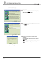
Setup starts.
The left screen appears. Check the description,
then click the Next > button.
5
Enter a user name and company name, then click
the Next > button.
6
Check the user name and company name
registered.
If the registration contents are correct, click the
Yes button.
When changing the registration contents, click the
No button to return to the previous screen.
(To the next page)
5-4
SOFTWARE INSTALLATION
INTRODUCTION
1
(From the previous page)
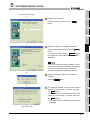
7 Register the product ID.
EXAMPLE SYSTEM OUTLINE
2
6 Enter the product ID, then click the Next >
button.
REQUIRED
EQUIPMENT FOR
START-UP
3
EQUIPMENT
SETUP
4
5
SOFTWARE
INSTALLATION
8 Specify the folder for installation destination.
To change the folder, click the Browse... button,
then specify the drive and folder for installation
destination.
6
CREATING A
DATABASE TABLE
When using the default folder, click the Next >
button.
9 When the left screen appears, installation is
complete.
OK
9
button.
FAQs
Click the
8
MES INTERFACE
CONFIGURATION
Up to 100 characters including “\MESIF” can be
used for the installation destination. This means
that up to 94 characters can be used when
specifying a destination folder as a directory.
ODBC SETTING
7
the OK button.
To not restart the computer, check the “No, I will
restart my computer later.” checkbox, then click
the
OK
button.
11 * It is recommended to restart the computer after
installation.
10
CONCISE ERROR
CODE LIST
10 To restart the computer, check the “Yes, I want to
restart my computer now.” checkbox, then click
11
TERMINOLOGY
5
Index
(To the next page)
5-5
5
SOFTWARE INSTALLATION
(From the previous page)
12 The dialog box for selecting the component to be
installed is displayed.
13 When installing the other software, select the
component to be installed with the radio button,
then click the Install button.
14 When the installation is complete, click the Exit
button.
15
(End)
After installing MES Interface Function Configuration Tool and DB Connection
Service Setting Tool, the following icons are registered.
5-6
6
CREATING A DATABASE TABLE
INTRODUCTION
1
CHAPTER 6 CREATING A DATABASE TABLE
This section explains the procedure for making a sample DB table using the database
Microsoft Access 2003. Two types of DB table shown below will be prepared.
Table design
3
Data
OrderTable
OrderCode
ProductCode
PlanNumber
Data type
Numerical
type
Text type
Numerical
type
Field size
Integer type
2
OrderCode
ProductCode
PlanNumber
1
EN
20
2
US
35
3
CN
25
4
EQUIPMENT
SETUP
Filed name
Integer type
History
* No data because this table is for “Insert” action.
Date_Time
Weight_mg
Text type
6
Date/time
type
Numerical
type
5
Field size
SOFTWARE
INSTALLATION
SerialCode
Data type
6
Single type
CREATING A
DATABASE TABLE
Filed name
REQUIRED
EQUIPMENT FOR
START-UP
Table name
EXAMPLE SYSTEM OUTLINE
2
6.1 General Description
6.2 OrderTable Creation
ODBC SETTING
7
(Start)
1 Start the Microsoft Office Access 2003 from the
Windows Start menu.
2 Select File on the menu bar and then click New.
MES INTERFACE
CONFIGURATION
8
FAQs
9
CONCISE ERROR
CODE LIST
10
(To the next page)
TERMINOLOGY
11
Index
6-1
6
CREATING A DATABASE TABLE
(From the previous page)
(To the next page)
6-2
3
Choose Blank Database from the menu appearing
at the right to create a new database.
4
Specify file name as “Sample_DB.mdb.” and click
the Create button.
5
The above step opens the following dialog box.
Select “Create a table in Design View.”
CREATING A DATABASE TABLE
INTRODUCTION
1
6 When a table properties window (Design View)
appears, enter into the first line “OrderCode” as
field name, “Number” as data type and “Integer”
as field size.
2
EXAMPLE SYSTEM OUTLINE
(From the previous page)
REQUIRED
EQUIPMENT FOR
START-UP
3
EQUIPMENT
SETUP
4
7 Enter into the 2nd line “ProductCode” as field
name, “Text” as data type and “2” as field size.
SOFTWARE
INSTALLATION
5
CREATING A
DATABASE TABLE
6
7
ODBC SETTING
8 Enter into the 3rd line “PlanNumber” as field
name, “Number” as data type and “Integer” as
field size.
MES INTERFACE
CONFIGURATION
8
FAQs
9
(To the next page)
CONCISE ERROR
CODE LIST
10
11
TERMINOLOGY
6
Index
6-3
6
CREATING A DATABASE TABLE
(From the previous page)
9
Select File on the menu bar and then click Save
As. In the dialog box that appears, enter
“OrderTable” in the Table Destination field and
select “Table” in the Type-of-affixation field. Click
the OK button.
10 When the following dialog box appears, select No.
11 Upon the completion of table saving, close Design
- View.
12 Next, select “OrderTable” and click the Open
button to bring it up to the screen.
13 When the table shows up, enter data as shown
below. Upon the completion of data entry, close
the table.
6-4
CREATING A DATABASE TABLE
INTRODUCTION
1
6.3 “History” Table Creation
“History” table is created in a similar way to the “OrderTable.”
EXAMPLE SYSTEM OUTLINE
2
(Start)
1 The operation of the DB interface function is
shown below.
REQUIRED
EQUIPMENT FOR
START-UP
3
EQUIPMENT
SETUP
4
SOFTWARE
INSTALLATION
5
6
CREATING A
DATABASE TABLE
2 When the screen for table properties (Design Review) appears, enter into the first line
“SerialCode” as field name, “Text” as data type
and “6” as field size.
ODBC SETTING
7
9
FAQs
3 Enter into the 2nd line “Date_Time” as field name
and “Date/Time” as data type.
MES INTERFACE
CONFIGURATION
8
CONCISE ERROR
CODE LIST
10
(To the next page)
11
TERMINOLOGY
6
Index
6-5
6
CREATING A DATABASE TABLE
(From the previou page)
6-6
4
Enter into the 3rd line “Weight_mg” as field name,
“Number” as data type and “Single” as field size.
5
Select File on the menu bar and then click Save
As. In the dialog box that appears, select “History”
in the Table Destination field and “Table” in the
type-of-affixation field. Click the OK button.
6
When the following dialog box appears, select No.
7
After saving the table, close the Design - View.
7
ODBC SETTING
INTRODUCTION
1
This section explains setting method for the following basic software (OS) and relational
databases.
• Basic software (OS): Microsoft Windows XP Professional Operating System
• Relational database : Microsoft Access 2003
2
EXAMPLE SYSTEM OUTLINE
CHAPTER 7 ODBC SETTING
Set the following conditions.
• Data source name*1 : SAMPLEDS
• Database name*2 : C:\mes\Sample_BD.mdb
EQUIPMENT
SETUP
Data source name can be set as desired.
The name in this setting is to be used as the [data source name] in [Server service setting].
The database name is the name for accessing a Microsoft Access database.
Specify the path in which the database file created in Microsoft Access is stored.
5
SOFTWARE
INSTALLATION
*2
4
(Start)
Clicking [Performance and Maintenance] on the
Control Panel displays the [Performance and
Maintenance] dialog box.
To display the Control Panel, select [Start]
[Control Panel].
6
7
ODBC SETTING
1
CREATING A
DATABASE TABLE
*1
REQUIRED
EQUIPMENT FOR
START-UP
3
When using software or relational database other than above, refer to (MES Interface
Module User's Manual )".
MES INTERFACE
CONFIGURATION
8
9
Clicking [Administrative Tools] displays
[Administrative Tools] dialog box.
FAQs
2
CONCISE ERROR
CODE LIST
10
TERMINOLOGY
11
Index
(To the next page)
7-1
7
ODBC SETTING
(From the previous page)
3
Double clicking [Data Sources (ODBC)] displays
[ODBC Data Source Administrator] dialog box.
Select the [System DSN] tab, then click the Add
button.
4
The [Create New Data Source] dialog box is
displayed, then select [Microsoft Access
Driver(*.mdb)].
5
The [ODBC Microsoft Access Setup] dialog box is
displayed. Set the following and click the
[Database] selection button.
• [Data source name]: SAMPLEDS
(To the next page)
7-2
ODBC SETTING
INTRODUCTION
1
(From the previous page)
Select the following and click the
OK
button.
• [Folder]: C: \ mes
• [Database Name]: Sample_DB.mdb
EXAMPLE SYSTEM OUTLINE
2
6 The [Select Database] dialog box is displayed.
REQUIRED
EQUIPMENT FOR
START-UP
3
7 Click the
OK
EQUIPMENT
SETUP
4
button in the [ODBC Microsoft
5
8 Click the
OK
SOFTWARE
INSTALLATION
Access Setup] dialog box.
button in the [ODBC Data
Source Administrator] dialog box.
6
CREATING A
DATABASE TABLE
(End)
ODBC SETTING
7
MES INTERFACE
CONFIGURATION
8
FAQs
9
CONCISE ERROR
CODE LIST
10
11
TERMINOLOGY
7
Index
7-3
8
MES INTERFACE CONFIGURATION
CHAPTER 8 MES INTERFACE CONFIGURATION
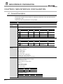
8.1 General Description
This section explains the procedure for specifying parameters using the MES Interface
Configuration Tool.
Table below lists the parameters to be specified.
Item of setting
Description
System settings
Default settings
Access target
Default settings
settings
Device tag settings Device tag name: GettingData
Sampling settings: Normal sampling for a period of one second.
Component name
1
Ocode
CPU name
ControlCPU
ControlCPU
Device
D100
Data type
Single precision
D300-D302
Character string,
Statistical type
-
2
Scode
3
Weight_g
ControlCPU
D400
Single precision
-
4
ReportingTrigger
ControlCPU
M0
Bit
-
6 characters
-
Device tag name: PuttingData
Sampling settings: Do not sample
Component name
1
2
Plan
CPU name
ControlCPU
PCode
ControlCPU
Server service
Server service name: SampleServer
settings
Server type: Database server
Device
D200
Data type
Single precision
Character string,
D202
2 characters
IP address: 192.168.3.1
Port number: 5112
User name: "Blank"
Password: "Blank"
Data source name: SAMPLEDS
Database type: Access 2003/2007
Communication timeout interval: 10 seconds
Job settings
Job name: GettingPlan
Enabled or not at module startup: Enabled
Trigger buffering: None
Trigger condition: At module startup
<Action 1>
Type of action: SELECT
Table name: OrderTable
DB-tab link settings:
Filed name
Tag
Component
ProductCode
PuttingData
PCode
PlanNumber
PuttingData
Plan
Select/update conditions
Filed name
OrderCode
8-1
Condition
=
Tag
GettingData
Component
OCode
Statistical type
-
MES INTERFACE CONFIGURATION
Item of setting
Description
Job name: Reporting
Enabled or not at module startup: Enabled
Trigger buffering: Provided
2
Component
Condition
ReportingTrigger
=
Tag/type
[Constant]
Component
ON
<Action 1>
3
Type of action: Operation
Substitution
tag
[Variable]
Component
Conversion
Operation
tag
GettingData
Component
Weight_g
Operator
/
Operation
tag
[Number]
Component
1000
4
EQUIPMENT
SETUP
<Action 2>
Type of action: Insert
Table name: History
DB-tag link settings:
5
[Date]
Module time
Weight_mg
[Variable]
Conversion
6
CREATING A
DATABASE
TABLE
Date_Time
7
ODBC SETTING
SCode
SOFTWARE
INSTALLATION
Component
GettingData
8
MES INTERFACE
CONFIGURATION
Tag
SerialCode
9
FAQs
Field name
REQUIRED
EQUIPMENT FOR
START-UP
Tag
GettingData
EXAMPLE SYSTEM OUTLINE
Trigger condition: Value monitoring startup
10
CONCISE ERROR
CODE LIST
Job settings
INTRODUCTION
1
11
TERMINOLOGY
8
Index
8-2
8
MES INTERFACE CONFIGURATION
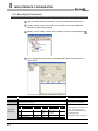
8.2 Specifying Parameters
1
Start the “MES Interface Configuration Tool” from the Windows Startup menu.
2
“System settings” and “Access target CPU settings” need not be established
because they take default settings.
3
Specify a “device setting.” Select “Device Settings” and click the [Add] button (
4
Enter “GettingData” into the Device Tag Name field and specify parameters as
shown below.
Setting item
Device name
Setting description
Setting method
GettingData
Text input
• Radio button selection (sampling)
Sampling setting Normal sampling; 1 second
Component name
Component
setting input
8-3
1
OCode
).
• Text input (No. of seconds)
CPU name
Device
Data type
Statistical
type
-
ControlCPU
D100
Single precision
Character string,
6 characters
-
2
SCode
ControlCPU
D300D302
3
Weight_g
ControlCPU
D400
Single precision
-
4
ReportingTrigger
ControlCPU
M0
Bit
-
• After inputting the information in a
row, click the [Add] button.
• Text input (component, device,
character/number)
• List selection (CPU, data type)
8
MES INTERFACE CONFIGURATION
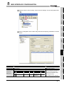
5
Specify another “device setting.” Select “Device Settings” and click the [Add] button
(
).
INTRODUCTION
1
EXAMPLE SYSTEM OUTLINE
2
REQUIRED
EQUIPMENT FOR
START-UP
3
EQUIPMENT
SETUP
4
Enter “PuttingData” into the Device tag name field and specify parameters as shown
below.
5
SOFTWARE
INSTALLATION
6
CREATING A
DATABASE
TABLE
6
ODBC SETTING
7
MES INTERFACE
CONFIGURATION
8
FAQs
9
Setting description
Setting method
PuttingData
Text input
Sampling settings Do not sample.
Component name
CPU name
Device
Statistical type
Component
setting input
1
2
Plan
PCode
11
Radio button selection
ControlCPU
ControlCPU
Statistical
type
D200
Single precision
-
D202
Character string,
2 characters
-
• After inputting the information in
a row, click the [Add] button.
• Text input (component, device,
TERMINOLOGY
Setting item
Device name
CONCISE ERROR
CODE LIST
10
Index
character/number)
• List selection (CPU, data type)
8-4
8
MES INTERFACE CONFIGURATION
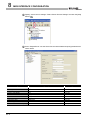
7
Specify "server service settings." Select "Server Service Settings" and click the [Add]
button (
8
).
Enter “SampleServer” into the Server Service Name field and specify parameters as
shown below.
Setting item
Setting description
Setting method
Server service name
SampleServer
Text input
Server type
Database server
List selection
IP address
192.168.3.1
Text input
Port No. (1024-65535)
5112
Text input
User name
Empty
-
Password
Empty
-
Confirm password
Empty
-
Data source name
SAMPLEDS
Text input
Database type
Access2003/2007
List selection
Communication timeout time (1-180) 10
8-5
Text input
8
MES INTERFACE CONFIGURATION
9
Specify “job settings.” Select “Job Settings” and click the [Add] button (
INTRODUCTION
1
).
EXAMPLE SYSTEM OUTLINE
2
REQUIRED
EQUIPMENT FOR
START-UP
3
EQUIPMENT
SETUP
4
5
SOFTWARE
INSTALLATION
10 Enter “GettingPlan” into the Job Name field and specify trigger conditions as shown
below.
CREATING A
DATABASE
TABLE
6
ODBC SETTING
7
MES INTERFACE
CONFIGURATION
8
Setting description
Setting method
GettingPlan
Text input
Enable at module startup
Place checkmark
Checkmark
Trigger buffering
Remove checkmark.
Checkbox reversion
Trigger conditions
First condition: At module startup
List selection
9
FAQs
Setting item
Job name
CONCISE ERROR
CODE LIST
10
11 Next, specify an action. Select “Communication action” in the list box as shown
below and click the [Add] button.
TERMINOLOGY
11
Index
8-6
8
MES INTERFACE CONFIGURATION
12 Choose "Select" in the list box for Action type and set the communication action
parameters as is shown below. (Default setting is acceptable for the exception
processing settings)
After the setting, SQL sentence to be sent to a database is automatically generated.
The generated SQL sentence can be confirmed in the [Generated SQL text] box on
the lower part of the screen.
Setting item
Setting description
Setting method
Action type
Select
List selection
Table name
OrderTable
Text input
• Text input
Field name
DB-tag link settings
Tag
Component
1
ProductCode
PuttingData
PCode
2
PlanNumber
PuttingData
Plan
(Field name)
• List selection
(Tag, Component)
• Text input
Field name
Select/Update conditions
OrderCode
Condition
=
Tag
GettingData
Component
OCode
(Field name)
• List selection
(Condition, Tag, Component)
8-7
8
MES INTERFACE CONFIGURATION
13 Specify another “job setting.” Select “Job Settings” and click the [Add] button (
).
INTRODUCTION
1
EXAMPLE SYSTEM OUTLINE
2
REQUIRED
EQUIPMENT FOR
START-UP
3
14 Enter “Reporting” into the Job Name field and specify trigger conditions as shown
below.
EQUIPMENT
SETUP
4
SOFTWARE
INSTALLATION
5
CREATING A
DATABASE
TABLE
6
ODBC SETTING
7
Setting item
Setting description
Setting method
Job name
Reporting
Text input
Enable at module startup
Place checkmark.
Checkmark
Trigger buffering
Place checkmark.
Checkmark
9
First condition: Value monitoring startup
Tag
Component
ReportingTrigger
Condition
=
Tag/Type
[Constant]
Component
List selection
ON
FAQs
GettingData
10
CONCISE ERROR
CODE LIST
15 Next, specify an action. Select “Operation action” in the list box as shown below and
click the [Add] button.
11
TERMINOLOGY
Trigger condition
MES INTERFACE
CONFIGURATION
8
Index
8-8
8
MES INTERFACE CONFIGURATION
16 Specify the aspects of operation action as shown in the diagram
below.
Setting item
Setting description
Setting method
• List selection
Substitution
tag
1
Operation action
[Variable]
Component
Conversion
Operation
tag
GettingData
(1)
Component Operator
Weight_g
(2)
/
Operation
tag
[Number]
(3)
Component
(Substitution tag,
Component, Operation
1000
(4)
tag (1), Component
(2), Operator,
Operation tag (3))
• Text input
(Component (4))
17 Specify another “action” Select “Communications action” in the list box as shown
below and click the [Add] button.
8-9
8
MES INTERFACE CONFIGURATION
2
EXAMPLE SYSTEM OUTLINE
18 Select “Insert” in the “Action Type” combo box list box and specify parameters for the
communication action as shown below.
After the setting, SQL sentence to be sent to a database is automatically generated.
The generated SQL sentence can be confirmed in the [Generated SQL text] box on
the lower part of the screen.
INTRODUCTION
1
REQUIRED
EQUIPMENT FOR
START-UP
3
EQUIPMENT
SETUP
4
SOFTWARE
INSTALLATION
5
CREATING A
DATABASE
TABLE
6
ODBC SETTING
7
Table name
History
Text input
Field name
settings
1
SerialCode
Tag
GettingData
Component
SCode
2
Date_Time
[Date]
Module time
3
Weight_mg
[Variable]
Conversion
• Text input
(Field name)
9
• List selection
(Tag, Component)
19 Upon the completion of the setting operation, save associated parameters. Select
Projects on the menu bar and then click Save As.
10
11
TERMINOLOGY
DB-tag link
8
MES INTERFACE
CONFIGURATION
Setting method
List selection
FAQs
Setting description
Insert
CONCISE ERROR
CODE LIST
Setting item
Action type
Index
8 - 10
8
MES INTERFACE CONFIGURATION
20 Enter “Sample_Config” into the File Name field and save the project.
21 Select [Menu] a [Online] a [Remote operation].
22 When the transfer setting screen in the diagram below is shown, input the IP
address, user name and password and click the [OK] button.
The default settings are given below.
IP address: 192.168.3.3
User name: QJ71MES96
Password: MITSUBISHI
23 The Compact Flash card is formatted with the following operations.
Formatting the Compact Flash card will erase all data on the Compact Flash card.
Back up required data before executing the following operations.
24 Check the Compact Flash card operation format and click the [Execute] button to
format the Compact Flash card.
25 Once formatting is complete, click the [Close] button and close remote operation.
Turn the power of the programmable controller CPU from OFF to ON and restart the
MES interface module.
8 - 11
MES INTERFACE CONFIGURATION
INTRODUCTION
1
8.3 Operational Check
8.3.1 General Description
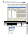
Select On-line on the menu bar and then click Write. Write parameter settings
established in Section 5 into associated fields.
4
EQUIPMENT
SETUP
8.3.2 Writing Parameters onto QJ71MES96 Module
1
3
REQUIRED
EQUIPMENT FOR
START-UP
The procedure described in this section checks the results of the entire process, from
writing parameters by the MES Interface Configuration Tool, to starting QJ71MES96
module, to writing data into the database.
EXAMPLE SYSTEM OUTLINE
2
SOFTWARE
INSTALLATION
5
2
When the target setting screen shown below appears, enter a user name and
password and click the OK button.
7
ODBC SETTING
Default settings are as follows:
User name: QJ71MES96
Password: MITSUBISHI
CREATING A
DATABASE
TABLE
6
MES INTERFACE
CONFIGURATION
8
FAQs
9
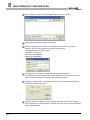
3
CONCISE ERROR
CODE LIST
10
Upon the completion of the writing step, reset the sequencer CPU to start the
QJ71MES96 module.
After resetting, switch the sequencer CPU to RUN.
11
4
TERMINOLOGY
8
When the QJ71MES96 module starts, writting data into the database starts
automatically.
Index
8 - 12
8
MES INTERFACE CONFIGURATION
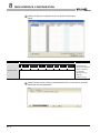
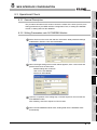
8.3.3 Checking Data Written into DB Table
8 - 13
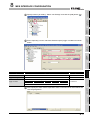
1
Open "C:/mes/Sample_DB.mdb" with Microsoft
Access 2003.
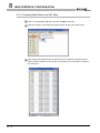
2
Selecting "History" and clicking the [Open] button will open the History table.
3
After starting the MES interface module, 35 pieces of data are "inserted" into the
History table at intervals of 10 seconds. The results can be checked in a chart like
the one below.
9
FAQs
INTRODUCTION
1
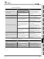
CHAPTER 9 FAQs
2
EXAMPLE SYSTEM OUTLINE
9.1 Troubleshooting by symptom
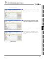
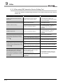
9.1.1 When using MES Interface Function Configuration Tool
(1) Common to all settings
module.
the connection route?
Is the MES interface module connected to
the network?
(Network connection status (X4) = ON)
Is it in "Online" mode?
Is there any problem on the computer?
MES Interface Function Configuration Tool
Have five MES Interface Function
will not start.
Configuration Tools already started?
setting.
• Correct the IP address setting.
• Ask your network administrator about the
firewall and proxy server settings.
• Connect the MES interface module to the
network.
• Change the mode to "Online".
• Replace it with another computer.
• Terminate any of the MES Interface
Function Configuration Tools and then
start another.
• Up to five MES Interface Function
Configuration Tools can be started.
The specified project file is incorrect or
Unable to import a project file.
Unable to import a CSV file.
corrupted.
Is there any inconsistency in the setting?
Did the number of settings exceed the
upper limit?
Is the CSV file description correct?
Is there any inconsistency in the setting?
Did the number of settings exceed the
• Check the setting and correct it if any.
• Check the number of settings.
• Correct the CSV file description.
• Check the setting and correct it if any.
(The text display is truncated.)
EQUIPMENT
SETUP
9
• Check the number of settings.
Is the tag set to data-write-disabled?
• Set the tag to data-write-enabled.
Is the column to narrow?
• Adjust the column width of the table.
10
11
TERMINOLOGY
tag.
All the text is not displayed in a table.
7
8
• Specify a correct project file.
[Device tag name] is not displayed for the
setting item by which data are written to a
6
FAQs
upper limit?
5
SOFTWARE
INSTALLATION
Configuration Tool to the MES interface
• Correct the IP address setting.
• Correct the user name and password
CREATING A
DATABASE
TABLE
Unable to connect MES Interface Function
correct?
Is the IP address duplicated?
Is there a firewall and/or a proxy server in
• Connect the cables properly.
ODBC SETTING
connection route?
Is the IP address setting correct?
Is the user name and password setting
Corrective action
MES INTERFACE
CONFIGURATION
Checked item
Is there any disconnection in the
4
CONCISE ERROR
CODE LIST
Symptom
REQUIRED
EQUIPMENT FOR
START-UP
3
This section explains troubleshooting information on the setting of MES Interface Function
Configuration Tool.
Index
9-1
9
FAQs
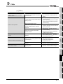
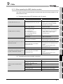
(2) [System setting]
Symptom
A desired device tag name is not displayed
in [DB buffering settings].
Checked item
Is the tag set to data-write-disabled?
Corrective action
• Set the tag to data-write-enabled.
(3) [Access target CPU settings]
Symptom
Checked item
Corrective action
• If it is any item other than the first one,
change the item or add an item.
Is it the first item?
• Since the control CPU is set as the first
item, deletion or setting change is not
allowed for it. (Only the CPU name can
Unable to change or delete an item in
be changed.)
[Access target CPU settings].
• As the error dialog box appears, identify
Is the selected item used in [Device tag
settings]?
the location, stop using it for another
item, and then delete the item.
• An item used for another item is unable
to be deleted.
9-2
9
FAQs
INTRODUCTION
1
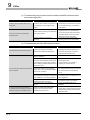
(4) [Device tag settings]
Is the selected item used in [Access error
notification setting] of [Server service
settings]?
Unable to set or change [Device tag name].
Is the same name used for [Server service
name] or another [Device tag name]?
item, and then delete the item.
• An item used for another item is unable
to be deleted.
• Because a unique name must be used
for [Server service name] and [Device tag
name], use a different name.
• Uncheck the [High-speed sampling]
Is [High-speed sampling] selected in
another [Device tag settings]?
checkbox in the [Device tag settings].
• Registration of [High-speed sampling] is
limited to one tag only.
• Delete the component setting with
selection of any other than the first item,
Is any other than the first item (Control
CPU) in [Access target CPU settings]
Unable to select [High-speed sampling].
selected in [CPU name] in [Component
setting input]?
or change the setting so that the first item
will be used for it.
• If [High-speed sampling] is selected, only
the first item in [Access target CPU
settings] (Control CPU) can be selected
for the tag component.
• Reduce the number of device points in
Is the number of device points set in the tag
setting more than 96?
the tag setting to 96 or less.
• When [High-speed sampling] is selected,
set tag component devices within the
total of 96 points.
• Stop using the tag for the setting item by
Is the tag used for a setting item by which
Unable to change the [Prohibit data writing]
setting.
data are written to the tag?
• [Completion notification] of [Handshake
which data are written to the tag, before
changing the setting.
• If the tag is used for a setting item by
operation], substitution tags of [Select] in
which data are written to the tag,
[Communication action], etc.
unchecking the [Prohibit data writing] box
is not allowed.
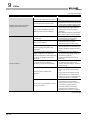
Is the same name used for another [Server
name].
service name] or [Device tag name]?
Unable to change [Server type].
A desired device tag name is not displayed
in [Access error notification setting].
Is the [Server service name] same as the
existing one?
Is the tag set to data-write-disabled?
6
7
8
Corrective action
• Because a unique name must be used
for [Server service name] and [Device tag
name], use a different name.
10
CONCISE ERROR
CODE LIST
Unable to set or change [Server service
5
• Correct the [Server service name].
• Set the tag to data-write-enabled.
11
TERMINOLOGY
Checked item
4
9
(5) [Server service settings]
Symptom
3
REQUIRED
EQUIPMENT FOR
START-UP
[Device tag settings].
the location, stop using it for another
EQUIPMENT
SETUP
settings] of [System setting]?
SOFTWARE
INSTALLATION
Unable to change or delete an item in
• As the error dialog box appears, identify
CREATING A
DATABASE
TABLE
Is the selected item used in [DB buffering
ODBC SETTING
Is the selected item used in [Job settings]?
EXAMPLE SYSTEM OUTLINE
2
Corrective action
MES INTERFACE
CONFIGURATION
Checked item
FAQs
Symptom
Index
9-3
9
FAQs
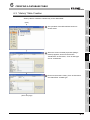
(6) [Job settings]
Symptom
Checked item
Corrective action
• Do not use Select actions in the job
Unable to set [DB buffering settings].
Is there any Select action set for the job?
where DB buffering is enabled.
• The DB buffering is not available for jobs
performing Select actions.
Unable to set a new variable.
Are there 64 variables that were already
defined in the job?
• Delete any unnecessary variable settings
of the job.
• Up to 64 variables can be set for one job.
• Select any other than [Handshake
Unable to select [Trigger 2] in [Trigger
Is [Handshake operation] selected for
conditions].
[Trigger 1]?
operation] for [Trigger 1].
• When [Handshake operation] is selected,
selection is not allowed for [Trigger 2].
A desired device tag name is not displayed
in [Completion notification] of [Handshake
operation].
A desired device tag name is not displayed
in the field of Substitution tag for [Select] in
[Communication action].
A desired device tag name is not displayed
in the field of Substitution tag in [Exception
Is the tag set to data-write-disabled?
• Set the tag to data-write-enabled.
Is the DB buffering enabled?
• Disable the DB buffering.
processing] of [Communication action].
A desired device tag name is not displayed
in the field of Substitution tag in [Operation
action].
A desired device tag name is not displayed
under [Notify errors (job cancellation) that
occur during job execution].
Unable to set [Exception processing] in
[Communication action].
9-4
Is [Insert] set for [Action type]?
• Set any other than [Insert] for [Action
type].
9
FAQs
INTRODUCTION
1
(7) [Online]
• Up to 8192 fields can be set within one
project.
• Select [Online] - [Transfer setup] and
Is the IP address set in [Transfer setup] of
[Online] correct?
3
correct the setting.
• Perform the online operation for the MES
interface module selected from [Online] [Transfer setup].
Send a PING request from the
Failed in online operation.
configuration computer to the IP address of
the MES interface module. Is there a
response?
Has the account set in [Transfer setup] of
[Online] been registered to the MES
interface module?
Unable to select [One-shot execution] from
Was the job for one-shot execution
[Online].
selected?
• If no response is returned, check if the
module is powered up or if the network is
properly connected.
• Select [Online] - [Transfer setup] and
correct the setting.
• Specify the account that is registered in
the MES interface module.
• Select the job for one-shot execution,
and then select [Online]
[One-shot
execution] from the menu.
• By the error code, check the error details
• Re-execute formatting of the
Is the MES interface module operation
• Stop the MES interface module
CompactFlash card.
the [Stop] state?
• Stop the MES interface module
operation, and then write the settings.
7
8
MES INTERFACE
CONFIGURATION
Is the MES interface module operation in
MES interface module.
operation, and then execute formatting.
9
FAQs
It takes time to write the settings to the
6
10
CONCISE ERROR
CODE LIST
stopped?
5
11
TERMINOLOGY
Failed to format the CompactFlash card.
and take corrective actions.
of GX Developer.
4
CREATING A
DATABASE
TABLE
Check for an error code in [System monitor]
EXAMPLE SYSTEM OUTLINE
more than 8192?
REQUIRED
EQUIPMENT FOR
START-UP
Is the total number of fields in the project
interface module.
• Delete any unnecessary field settings.
EQUIPMENT
SETUP
Unable to write a project to the MES
2
Corrective action
SOFTWARE
INSTALLATION
Checked item
ODBC SETTING
Symptom
Index
9-5
9
FAQs
9.1.2 When using DB Connection Service Setting Tool
This section explains troubleshooting information on the setting of DB Connection Service
Setting Tool.
Symptom
Checked item
Corrective action
• Terminate the already started DB
Unable to start DB Connection Service
Has another DB Connection Service
Setting Tool.
Setting Tool been already started?
• Only one DB Connection Service Setting
Was a user ID having the administrator
• Log in again with a user ID having the
Connection Service Setting Tool.
Tool can be activated.
authority used for the login?
administrator authority.
• Uncheck the [Limit IP addresses permit
Unable to reflect the setting.
Is there no permitted IP address?
to connect] checkbox, or add an IP
address for which connection is
permitted
• Uncheck the [Limit IP addresses permit
Unable to export a file.
Is there no permitted IP address?
to connect] checkbox, or add an IP
address for which connection is
permitted.
Is the file set in [Output destination] readAn access log output error is recorded in
[Event Viewer] of [Administrative Tools] in
Windows .
only?
Is the access to the folder containing the
file set in [Output destination] authorized?
Is the drive space of the server computer
full?
Is the file set in [Output destination] read-
An SQL failure log output error is recorded
in [Event Viewer] of [Administrative Tools]
in Windows .
only?
Is the access to the folder containing the
file set in [Output destination] authorized?
Is the drive space of the server computer
full?
• Correct the file specification.
• Check the right of access to the folder.
• Check the free space on the drive.
• Correct the file specification.
• Check the right of access to the folder.
• Check the free space on the drive.
Does the following file exit in the installing
[The DBConnector service failed to start
destination directory of [DB connection
due to the following error: The system
service and Setting tool]?
cannot find the file specified.] is recorded in
[MESIF\DBConnector.exe]
Setting tool] and restart the computer
[Event Viewer] of [Administrative Tools] in
Has the computer been restarted after
before reinstallation.
Windows .
uninstalling [DB connection service and
Setting tool]?
9-6
• Uninstall [DB connection service and
9
FAQs
INTRODUCTION
1
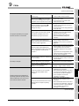
9.1.3 When operating the MES interface module
(1) Troubleshooting about LED indication and I/O signals
Corrective action
• If a watchdog timer error is identified,
The RUN LED does not turn on.
Is the Watchdog timer error (X1F) ON?
please consult your local Mitsubishi
representative, explaining a detailed
description of the problem.
Is the battery connected? Or, has the
• Check the battery connection.
battery voltage dropped?
• Replace the battery.
4
Is any of the error detection signals (X11,
X12, X16 and X1C) ON?
The ERR. LED is on or flashing.
• According to the error code obtained by
X11: Sampling error
the error detection shown on the left,
X12: Information linkage error
identify the error cause and take
X16: Access target CPU error
corrective actions.
X1C: Another error
Check the error code in [System monitor] of
GX Developer.
REQUIRED
EQUIPMENT FOR
START-UP
3
• Wait for startup of the module.
• By the error code, identify the error and
EQUIPMENT
SETUP
Checked item
Is the module in preparation?
5
SOFTWARE
INSTALLATION
Symptom
2
EXAMPLE SYSTEM OUTLINE
This section shows the troubleshooting of problems that may arise during operation of the
MES interface module.
6
take corrective actions.
[Access target CPU settings], it may take
several minutes until X0 turns ON.
Module READY (X0) does not turn ON, or it
Are there many files in the installed
CompactFlash card?
CompactFlash card, it takes time to turn
X0 ON.
• Delete unnecessary files from the
CompactFlash card.
Is file access stopped? (X2 is ON?)
• Cancel the file access stop.
8
• If many files are stored in the
CompactFlash card status (X1) does not
turn ON, or it takes time to turn ON.
Are there many files in the installed
CompactFlash card?
7
ODBC SETTING
takes time to turn ON.
• If many files are stored in the
CompactFlash card, it takes time to turn
X1 ON.
• Delete unnecessary files from the
CompactFlash card.
MES INTERFACE
CONFIGURATION
Is the module in preparation?
CREATING A
DATABASE
TABLE
• Depending on the number of items set in
9
(2) Troubleshooting about network connection
• Change the mode to "Online".
Is the MES interface module connected to
• Connect the MES interface module to the
module.
Is there any disconnection in the
connection route?
network.
• Connect the cables properly.
Is the IP address duplicated?
• Correct the IP address setting.
Is there a firewall and/or a proxy server in
• Ask your network administrator about the
the connection route?
Is there a problem with the computer?
10
CONCISE ERROR
CODE LIST
Is it in "Online" mode?
the network? (X4 = ON)
Unable to access the MES interface
Corrective action
FAQs
Checked item
11
TERMINOLOGY
Symptom
firewall and proxy server settings.
• Replace it with another computer.
Index
9-7
9
FAQs
(3) Troubleshooting about communication between the MES interface module
and access target CPU
Symptom
Checked item
Is a remote password set for the GX
Corrective action
• Remove the remote password set for the
Unable to access another station via Q
Developer communication port (UDP/IP) of
GX Developer communication port (UDP/
series E71.
the Q series E71 on the target or relay
IP) of the Q series E71 on the target or
station?
relay station.
• Mount a MES interface module to the
Is MES interface accessing the Redundant
An error occurs when accessing the
CPU of other station?
Redundant CPU.
extension base unit of the Redundant
CPU that is access target and access it.
The MES interface cannot access the
Redundant CPU of other station.
Is system switching consecutively
occurring?
• Review the system so that system
switching will not occur consecutively.
(4) Troubleshooting about the DB interface function
Symptom
Checked item
Corrective action
• If "Stopped" is displayed, execute
The DB interface function does not work.
Is "Running" displayed in the status
[Restart] from [Remote operation], turn
indication area of [Remote operation]?
the power OFF and ON, or reset the
programmable controller CPU.
Was the computer restarted after installing
relational database?
• Restart the computer.
Is the port No. set in [Service port] of DB
Connection Service Setting Tool the same
• Set the same value.
as the port No. set in [Port No.] of [Server
Communication is not available if
service settings] of MES Interface Function
different port numbers are set.
Configuration Tool?
No communication has been made with the
server computer.
Is the firewall function of the operating
system (OS) or security software enabled
on the server computer?
Is the port specified in [Service port] of DB
the TCP/IP port to be used (Default:
5112).
• Change the port number to another that
is not being used for the database or any
for the database or any other application?
other application.
installed in the server computer?
Is the ODBC setting of the database
correct?
Is there any setting that enables data
processing is set, the average, maximum or writing to the tag component where
minimum value to be calculated is reset.
the communication of the port number for
Connection Service Setting Tool being used
Has any Check Point software been
In the tag component where statistical
• Disable the firewall setting. Or, enable
statistical processing is set?
• Uninstall the Check Point software.
• Correct the ODBC setting of the
database.
• Disable the write setting.
• Writing data to the tag component where
statistical processing is set will reset the
statistical values.
(To the next page)
9-8
9
FAQs
(From the previous page)
2
cause and take corrective actions.
• If no startup data is logged, refer to the
[Startup logging] setting are met, is the
following:
startup logged in [Event log] of [Working
Refer to the symptom item "Job will not
log]?
start up."
In [Change job status] of [Remote
operation], is [Disable writing to database]
• Enable writing to the database.
4
set?
Has an error occurred in the access log of
DB Connection Service?
Are the relevant records or table locked on
the database when inserting or updating
Values will not be stored in the database.
data?
In [Connection result of previous job
execution] of [Remote operation], is
"Connected" displayed under [Result]?
• If an error has occurred, identify the error
cause and take corrective actions.
• Unlock them on the database and
execute it.
5
If they are locked, the execution is
delayed until they are unlocked.
• If "Disconnected" is displayed, correct
the setting of [Server service settings].
• Check the network connection route to
the database server computer.
• Set the database being used.
Configuration Tool correct?
• Check if [Select/Update conditions] are
met.
• Check if there is any missing field into
Is No. of updated or inserted records
indicated as 0 in the access log of DB
Connection Service?
which a value is to be inserted.
• Check if the uniqueness constraint of the
database (PRIMARY KEY constraint) is
violated.
• Check if the value to be stored exceeds
the number of characters defined for the
field.
Has an error occurred in [Error log] of
[Working log]?
When trigger conditions of a job with
Database values will not be stored in
programmable controller devices.
• If an error has occurred, identify the error
cause and take corrective actions.
following:
startup logged in [Event log] of [Working
Refer to the symptom item "Job will not
log]?
start up."
operation], is [Disable writing to PLC
device] set?
Has an error occurred in the access log of
DB Connection Service?
7
8
9
• If no startup data is logged, refer to the
[Startup logging] setting are met, is the
In [Change job status] of [Remote
6
CREATING A
DATABASE
TABLE
Is the [Database type] setting in [Server
service settings] of MES Interface Function
REQUIRED
EQUIPMENT FOR
START-UP
cause and take corrective actions.
EQUIPMENT
SETUP
[Working log]?
SOFTWARE
INSTALLATION
case, is there an error in [Error log] of
3
• If an error has occurred, identify the error
ODBC SETTING
If the startup log is identified in the above
MES INTERFACE
CONFIGURATION
When trigger conditions of a job with
• If an error has occurred, identify the error
FAQs
[Working log]?
10
• Enable writing to programmable
controller devices.
• If an error has occurred, identify the error
cause and take corrective actions.
CONCISE ERROR
CODE LIST
Has an error occurred in [Error log] of
Corrective action
EXAMPLE SYSTEM OUTLINE
Checked item
11
(To the next page)
TERMINOLOGY
Symptom
INTRODUCTION
1
Index
9-9
9
FAQs
(From the previous page)
Symptom
Checked item
Is No. of selected records indicated as 0 in
the access log of DB Connection Service?
Was the relevant device value manipulated
in the programmable controller CPU?
Database values will not be stored in
Corrective action
• Check if [Select/Update conditions] are
met.
• Do not manipulate the device value in the
programmable controller CPU at the time
of writing from the MES interface module.
• Correct the set number of databases, or
programmable controller devices.
change the number of [Server service
Is the number of databases set for the
database server computer sufficient?
settings] items to the set number of
databases.
• One database connection must be used
for one item of [Server service settings].
Has an error occurred in [Error log] of
[Working log]?
Did the [Trigger conditions] change from
false to true completely?
Did the [Combination] of [Trigger
conditions] change from false to true
completely?
When [Value monitoring startup] is set for
[Trigger conditions], is the time for the
monitoring target device value change long
enough for the sampling interval of the
device tag?
• If an error has occurred, identify the error
cause and take corrective actions.
• Correct the [Trigger conditions].
• Start the job when the [Trigger
conditions] change from false to true.
• Correct the [Trigger conditions].
• Start the job when the [Combination] of
[Trigger conditions] change from false to
true.
• Increase the time for the monitoring
target device value change. (Latch it in
the sequence program.)
• Shorten the sampling interval of the
device tag.
• Enable the job.
Job will not start up.
In [Change job status] of [Remote
operation], is the job set to be disabled?
• To enable the job at startup of the
module, select [Job settings] - [Enable at
module startup].
• Terminate the job that is in execution, or
use another [Server service settings]
Is there any other ob that is being
executed?
item.
• If a job uses the same [Server service
settings] item that is currently used for
another job, the job is not executed until
another job execution is completed.
• If an error has occurred, identify the error
cause and take corrective actions.
Has an error or job cancellation occurred
during job execution?
• When the job uses a tag component for
which [Moving average], [Moving
maximum] or [Moving minimum] is
specified, check if sampling for the
specified number of times is completed.
(To the next page)
9 - 10
9
FAQs
• When executing the program associated
with the display, ensure that the
application server personal computer is
logged on.
Was the program associated with the
display executed with multiple users logged
on to the application server personal
computer?
• When executing the program associated
with the display, only one user logged on
to the application server personal
computer is displayed on the program
screen.
Log all users off of the application server
personal computer, and then execute
with only one user logged on.
Were the trigger conditions for multiple jobs
met concurrently?
• If the trigger conditions for multiple jobs
are met concurrently, startup of some job
may be delayed.
Was the job execution time prolonged?
• If the job execution time is prolonged,
startup of the next job may be delayed.
Was the value in the Monitoring interval
timeout count area (buffer memory
address: 11510) increased?
• Check and correct the number of job
settings or trigger condition settings.
Is there any problem on the connection
routes to all of the database server
computers.
• Check the connections with all of the
database server computers.
• When buffered SQL texts are to be sent
to more than one destination, unless the
communication with all the database
server computers is recovered,
resending is not started.
Are the DB Connection Services in all the
database server computers operating
normally?
• Check each of the DB Connection
Services in all the database server
computers.
• When buffered SQL texts are to be sent
to more than one destination, unless DB
Connection Services in all the database
server computers are operating,
resending is not started.
Selecting [Resend] from [DB buffering
operation] of [Remote operation] will not
resend buffered SQL texts of the job for
which manual resend is selected.
(To the next page)
EXAMPLE SYSTEM OUTLINE
Was the program associated with the
display executed with the application server
personal computer logged off?
REQUIRED
EQUIPMENT FOR
START-UP
Was a program executed which requires
administrator privileges (users in the
administrators group) for execution?
• Programs which require administrator
privileges (users in the administrators
group) cannot be executed.
• Specify a program which does not
require administrator privileges for
execution.
3
4
EQUIPMENT
SETUP
• Set a password of the account, or use
another account that does not have an
empty password.
• An account that has an empty password
cannot be used.
5
SOFTWARE
INSTALLATION
Was the password of the Windows
account specified in [Server service
settings] set empty?
2
6
CREATING A
DATABASE
TABLE
Was the Windows account specified in
[Server service settings] used to log on the
application server computer once or more?
• Use the account that has been used to
log on once or more.
• An account that has not been used
before cannot be used.
7
ODBC SETTING
• If an error has occurred, identify the error
cause and take corrective actions.
8
MES INTERFACE
CONFIGURATION
Job startup is delayed.
Has an error occurred in [Error log] of
[Working log]?
9
FAQs
execution function is not executed.
Corrective action
10
CONCISE ERROR
CODE LIST
The program specified by the program
Checked item
11
TERMINOLOGY
(From the previous page)
Symptom
INTRODUCTION
1
Index
9 - 11
9
FAQs
(From the previous page)
Symptom
Data such as DB buffering status, No. of
DB bufferings, DB buffer full, or DB buffer
utilization will not be stored in the tag
component which is selected in [DB
buffering settings] of [System setting].
Failed to communicate with the server
computer several times after module
startup.
Checked item
Corrective action
Was the setting that enables data writing to
the tag component made in [Job settings]?
• Select another tag component, or check
the [Job settings] and disable data writing
to the relevant tag component.
Was the device value of the relevant tag
component manipulated in the
programmable controller CPU?
• Specify another device. Or do not
manipulate the relevant device value in
the programmable controller CPU.
Was the programmable controller powered
ON immediately after OFF?
• Turn OFF the programmable controller,
and after several minutes, turn it ON.
Is there any problem on the server
computer?
• Restart the server computer.
(5) Troubleshooting about the XML processing function
Symptom
Checked item
Corrective action
• When "Stopped" is displayed, execute
The XML processing function does not
Is "Running" displayed in the status
work.
indication area of [Remote operation]?
[Restart] from [Remote operation].
Alternatively, turn the power OFF and
then ON, or reset the programmable
controller CPU.
(6) Troubleshooting about the time synchronization function
Symptom
Checked item
Time is not synchronized with the SNTP
Is the [SNTP server address] setting
server computer.
correct?
9 - 12
Corrective action
• Correct the [SNTP server address]
setting.
10
CONCISE ERROR CODE LIST
INTRODUCTION
1
CHAPTER 10 CONCISE ERROR CODE LIST
Check MES interface module error codes with the information linking function setting tool.
EXAMPLE SYSTEM OUTLINE
2
10.1 Viewing MES Interface Module Error Codes
Select [Online] from the menu a [Operation History] menu.
2
The [Operation History] will appear. Proceed referring to the explanation below.
REQUIRED
EQUIPMENT FOR
START-UP
3
1
EQUIPMENT
SETUP
4
SOFTWARE
INSTALLATION
5
CREATING A
DATABASE
TABLE
6
(1) Error log
Refer to the error log (error and system information) and check the error codes.
Error code
The date and time of the error (information) occurrence is displayed.
*3
Summary
The code for the error is displayed.
An error message and system information is displayed.
*1. When using SNTP with synchronized time, the time of the No. 1 CPU will displayed for the interval
from module startup until the time query to the SNTP server succeeds.
*2. Date will not be displayed for errors (information) occurring before the time from the No. 1 CPU is
obtained.
*3. Error codes will not be displayed in the case of system information.
MES INTERFACE
CONFIGURATION
Date*1*2
8
Description
9
FAQs
Item
ODBC SETTING
7
10
1
CONCISE ERROR
CODE LIST
(2) Error code updates
Clicking the [Update] button will update the error codes.
11
1
TERMINOLOGY
(3) Error log clear
Clicking the [Clear History] button will clear the error log.
Index
10 - 1
10
CONCISE ERROR CODE LIST
10.2 Viewing Server Computer Error Codes
The method of checking server computer error codes is shown below.
(1) DB connection service access log
Open the log file below with a text editor and check the error codes.
"C:\MELSEC\MESIF\dbConnector.log"
(2) DB connection service SQL failure log
Open the log file below with a text editor and check the error codes.
"C:\MELSEC\MESIF\sqlFailed.log"
(3) Windows event log
10 - 2
1
Select [Start] a [Control Panel] from the Windows Start menu to display the Control
Panel.
2
Select [Performance and Maintenance] a [Administrative Tools] to display
Administrative Tools.
3
Double click on [Event Viewer], check the DB connection service error codes, check
the error and take corrective action.
10
CONCISE ERROR CODE LIST
INTRODUCTION
1
10.2.1 Log Format
The log format used in the explanations in this section is shown below.
EXAMPLE SYSTEM OUTLINE
2
[Date] [Error Code] message line feed
4 integers (single-byte numbers)
Year-month break
bol 5th byte
"/" (single-byte slash: 2Fh)
Month
bol 6-7th bytes
2 integers (01-12) (single-byte numbers)
Month-day break
bol 8th byte
"/" (single-byte slash: 2Fh)
Day
bol 9-10th bytes
2 integers (01-31) (single-byte numbers)
Day-hour break
bol 11th byte
" " (single-byte space: 20h)
Hour
bol 12-13th bytes
2 integers (00-23) (single-byte numbers)
":" (single-byte colon: 3Ah)
REQUIRED
EQUIPMENT FOR
START-UP
3
4
Hour-minute break
bol 14th byte
Output
Minute
bol 15-16th bytes
2 integers (00-59) (single-byte numbers)
character
Minute-second break
bol 17th byte
":" (single-byte colon: 3Ah)
Second
bol 18-19th bytes
2 integers (00-59) (single-byte numbers)
Second-millisecond break
bol 20th byte
"." (single-byte period: 2Eh)
Millisecond
bol 21-23rd bytes
3 integers (00-999) (single-byte numbers)
Error code millisecond break
bol 24th byte
" " (single-byte space: 20h)
[Error Code]
bol 25-34th bytes
"0x" + 8 hexadecimal single-byte digits
Error code message break
bol 35th byte
" " (single-byte space: 20h)
Message
bol 36th byte on
Follow specifications for each log.
Line feed
eol
CR + LF(0Dh, 0Ah)
EQUIPMENT
SETUP
[Date]
Description
bol 1-4th bytes
5
SOFTWARE
INSTALLATION
Item
Year
CREATING A
DATABASE
TABLE
6
ODBC SETTING
7
MES INTERFACE
CONFIGURATION
8
FAQs
9
CONCISE ERROR
CODE LIST
10
TERMINOLOGY
11
Index
10 - 3
10
CONCISE ERROR CODE LIST
(1) Access Log
Internal communication between the MES interface module and the DB connection
service is output in the access log.
Access log details are shown here.
(a) Service start/end
• Start
Item
Description
Output log format
[Date] [Error Code] Service Start
Example
2005/07/01 12:00:00.000 0xL00000000 Service Start
• End
Item
Description
Output log format
[Date] [Error Code] Service Stop
Example
2005/07/01 12:00:00.000 0xL00000000 Service Stop
(b) MES interface module connection/disconnection
• Connection
Item
Output log format
Example
Description
[Date] [Error Code] SID [Section ID]:MIFWS Connected:[Connection origin IP]:[Connection target data
source]:[Connection ID]
2005/07/01 12:00:00.000 0xL00000000 SID 0:MIFWS Connected:192.168.3.3:DataSource:ID
• Disconnection
Item
Output log format
Example
10 - 4
Description
[Date] [Error Code] SID [Section ID]:MIFWS Disconnected:[Connection origin IP]:[Connection target data
source]:[Connection ID]
2005/07/01 12:00:00.000 0xL00000000 SID 0:MIFWS Disconnected:192.168.3.3:DataSource:ID
10
CONCISE ERROR CODE LIST
Output
Success
log format Failure
Success
Example
Description
[Date] [Error Code] SID [Section ID]:DB Connect:[Connection target data source]:[Connection ID]:Success
[Date] [Error Code] SID [Section ID]:DB Connect:[Connection target data source]:[Connection ID]:Failed
Database Message [Database error number][Database cause of error message]
2007/10/01 12:00:00.000 0xL00000000 SID 00000001:DB Connect:DataSource:ID:Success
2007/10/01 12:00:00.000 0xL20400022 SID 00000001:DB Connect:DataSource:ID:Failed
Failure
Database Message 0xL00000319 [Oracle][ODBC][Ora]ORA-01017: invalid username/password: logon
• Disconnection
Database Message [Database error number][Database cause of error message]
2007/10/01 12:00:00.000 0xL00000000 SID 00000001:DB Disconnect:DataSource:ID:Success
EXAMPLE SYSTEM OUTLINE
6
CREATING A
DATABASE
TABLE
Success
7
ODBC SETTING
Example
[Date] [Error Code] SID [Section ID]:DB Disconnect:[Connection target data source]:[Connection ID]:Failed
8
MES INTERFACE
CONFIGURATION
log format Failure
[Date] [Error Code] SID [Section ID]:DB Disconnect:[Connection target data source]:[Connection ID]:Success
9
FAQs
Success
10
CONCISE ERROR
CODE LIST
Output
5
Description
11
TERMINOLOGY
Item
4
EQUIPMENT
SETUP
denied
3
SOFTWARE
INSTALLATION
Item
2
REQUIRED
EQUIPMENT FOR
START-UP
(c) Database connection/disconnection
For details on [Database error number] and [Database cause of error message] in
the output log format at the time of failure, check each database's manual.
Depending on the [Error code], the Database Messages below may not be output.
Check the error and take corrective action according to the error code.
• Connection
INTRODUCTION
1
Index
10 - 5
10
CONCISE ERROR CODE LIST
(d) SQL statement receiving/processing results
For details on [Database error number] and [Database cause of error message] in
the output log format at the time of failure, check each database's manual.
Depending on the [Error code], the Database Messages below may not be output.
Check the error and take corrective action according to the error code.
• SELECT
Item
Output
Success
log format Failure
Success
Example
Failure
Description
[Date] [Error Code] SID [Section ID]:SQL<[SQL statement]>:Success ([selection code number])
[Date] [Error Code] SID [Section ID]:SQL<[SQL statement]>:Failed
Database Message [Database error number][Database cause of error message]
2007/10/01 12:00:00.000 0xL00000000 SID 00000001:SQL<SELECT COL from TABLE>:Success(1)
2007/10/01 12:00:00.000 0xL20600023 SID 00000001:SQL<SELECT COLL from TABLE>:Failed
Database Message 0xL00000388 [Oracle][ODBC][Ora]ORA-00904: "COLL": invalid identifier
• UPDATE
Item
Output
Success
log format Failure
Success
Example
Failure
Description
[Date] [Error Code] SID [Section ID]:SQL<[SQL statement]>:Success ([update code number])
[Date] [Error Code] SID [Section ID]:SQL<[SQL statement]>:Failed
Database Message [Database error number][Database cause of error message]
2007/10/01 12:00:00.000 0xL00000000 SID 00000001:SQL<UPDATE TABLE SET COL = '1'>:Success(1)
2007/10/01 12:00:00.000 0xL20600023 SID 00000001:SQL<UPDATE TABLE SET COL = 'COL'>:Failed
Database Message 0xL000006ba [Oracle][ODBC][Ora]ORA-01722: invalid number
• INSERT
Item
Output
Success
log format Failure
Success
Example
Failure
10 - 6
Description
[Date] [Error Code] SID [Section ID]:SQL<[SQL statement]>:Success ([insert code number])
[Date] [Error Code] SID [Section ID]:SQL<[SQL statement]>:Failed
Database Message [Database error number][Database cause of error message]
2007/10/01 12:00:00.000 0xL00000000 SID 00000001:SQL<INSERT INTO TABLE ( COL ) VALUES
('1')>:Success(1)
2007/10/01 12:00:00.000 0xL20600023 SID 00000001:SQL<INSERT INTO TABLEE ( COL ) VALUES ('1')>:Failed
Database Message 0xL000003ae [Oracle][ODBC][Ora]ORA-00942: table or view does not exist
10
CONCISE ERROR CODE LIST
INTRODUCTION
1
• COMMIT
Item
log format Failure
Example
Success
Description
[Date] [Error Code] SID [Section ID]:COMMIT:Success
2
[Date] [Error Code] SID [Section ID]:COMMIT:Failed
Database Message [Database error number][Database cause of error message]
EXAMPLE SYSTEM OUTLINE
Output
Success
2007/10/01 12:00:00.000 0xL00000000 SID 00000001:COMMIT:Success
• ROLLBACK
Output
Success
log format Failure
Example
Success
3
Description
REQUIRED
EQUIPMENT FOR
START-UP
Item
[Date] [Error Code] SID [Section ID]:ROLLBACK:Success
[Date] [Error Code] SID [Section ID]:ROLLBACK:Failed
Database Message [Database error number][Database cause of error message]
2007/10/01 12:00:00.000 0xL00000000 SID 00000001:ROLLBACK:Success
4
• GetNext (request for next record)
Success
log format Failure
Example
Success
EQUIPMENT
SETUP
Output
Description
[Date] [Error Code] SID [Section ID]:GetNext:Success
[Date] [Error Code] SID [Section ID]:GetNext:Failed
5
Database Message [Database error number][Database cause of error message]
2007/10/01 12:00:00.000 0xL00000000 SID 00000001:GetNext:Success
SOFTWARE
INSTALLATION
Item
(e) Program execution receiving/processing result
Description
CREATING A
DATABASE
TABLE
2007/10/01 12:00:00.000 0xL00000000 ProgramExec: 192.168.3.3:<hoge.exe>:Success(0)
7
ODBC SETTING
Example
8
MES INTERFACE
CONFIGURATION
[Date] [Error Code] SID SID ProgramExec:[Connection origin IP]:<[Command line]>:Failed
9
FAQs
log format Failure
Success
6
[Date] [Error Code] SID ProgramExec:[Connection origin IP]:<[Command line]>:Success([Return value])
10
CONCISE ERROR
CODE LIST
Success
11
TERMINOLOGY
Item
Output
Index
10 - 7
10
CONCISE ERROR CODE LIST
(2) SQL failure log
When an error occurs while executing SQL statements in the database, the error
details are output to the SQL failure log.
SQL failure log details are shown below.
For details on [Database error number] and [Database cause of error message] in the
output log format at the time of failure, check each database's manual.
Depending on the [Error code], the Database Messages below may not be output.
Check the error and take corrective action according to the error code.
Item
Output log format
Example
10 - 8
Description
[Date] [Error Code] [Connection target data source]:[SQL statement]
Database Message [Database error number][Database cause of error message]
2007/10/01 12:00:00.000 0xL00000000 DataSource:INSERT INTO TABLE ( COL ) VALUES ('')>:
Database Message 0xL00000388 [Oracle][ODBC][Ora]ORA-00904: "COL" :invalid identifier
10
CONCISE ERROR CODE LIST
INTRODUCTION
1
10.3 Error Code List
The error code list is shown below.
EXAMPLE SYSTEM OUTLINE
2
10.3.1 Error codes for the MES interface module
Processing code error
• Check the CPU(s) on the
access route.
0046h
Station No.
specification error
• Check the station number
setting in [Access target CPU
settings].
0047h
Receive data error
• Check the CPU(s) on the
access route.
00D8h
Protocol error
00D9h
Address error
00DBh
Write error
00E0h
Station No. error
• Check the station number
setting in [Access target CPU
settings].
00E1h
Processing mode error
• Check the PLC series in
[Access target CPU settings].
00E2h
Intelligent function
module specification
error
0049h
004Eh
System error
0050h
• Please consult your local
Mitsubishi representative,
explaining a detailed
description of the problem.
0064h
0065h
Channel No. error
System error
Routing parameter
error
0066h
Data send error
0067h
Data receive error
0080h
Read size error
0081h
Device type error
• Check the Ethernet module
setting of the access target
CPU.
• Please consult your local
Mitsubishi representative,
explaining a detailed
description of the problem.
• Set routing parameters to the
CC-Link IE, MELSECNET/H,
and/or MELSECNET/10
module(s).
• Check the CPU(s) on the
access route.
• Correct the device type entered
in [Device tag settings].
Link specification error
• Check the access route
referring to the accessible
range.
00E8h
System error
• Please consult your local
Mitsubishi representative,
explaining a detailed
description of the problem.
00E9h
Link timeout
• Reconnect the access target
on the access route.
00EAh
Special module BUSY
• Examine the hardware of the
intelligent (or special) function
module.
00ECh
Access target BUSY
• Check the access target.
00F0h
Link error
• Restore the link to connect the
station on the access route.
00F1h
Special module bus
error
00F2h
Special module
timeout
0100h
to
0104h
0180h
Device point error
0084h
Write size error
0085h
Link parameter error
• Set a correct link parameter for
the programmable controller
CPU(s) on the access route.
0087h
to
0089h
System error
• Please consult your local
Mitsubishi representative,
explaining a detailed
description of the problem.
00D2h
RUN time disable error
• Check the CPU(s) on the
access route.
• Examine the hardware of the
intelligent (or special) function
module.
System error
• Please consult your local
Mitsubishi representative,
explaining a detailed
description of the problem.
Switch setting error
• Check the intelligent function
module switch setting.
• Conduct the hardware test
again.
0110h
• Check the CPU(s) on the
access route.
0083h
" buffer
00E4h
0112h
Device No. error
\G
memory data in [Device tag
settings].
Other data error
• Correct the device number
entered in [Device tag settings].
0082h
• Correct the "U
00E3h
0051h
0055h
• Check the CPU(s) on the
access route.
• Check the CPU(s) on the
access route.
0048h
004Dh
• Check the cables on the
access route.
(To the next page)
REQUIRED
EQUIPMENT FOR
START-UP
Receive data length
error
4
EQUIPMENT
SETUP
0045h
00D7h
5
SOFTWARE
INSTALLATION
System error
• Please consult your local
Mitsubishi representative,
explaining a detailed
description of the problem.
System error
3
6
CREATING A
DATABASE TABLE
0041h
to
0044h
00D4h
Action
• Please consult your local
Mitsubishi representative,
explaining a detailed
description of the problem.
7
ODBC SETTING
Response time-out
error
• Correct [Access target CPU
settings].
• Check the communication
cable status and access target
CPU status.
Error name
8
MES INTERFACE
CONFIGURATION
System error
Error code
9
FAQs
0002h
Action
• Please consult your local
Mitsubishi representative,
explaining a detailed
description of the problem.
10
CONCISE ERROR
CODE LIST
0001h
Error name
11
TERMINOLOGY
Error code
Index
10 - 9
10
CONCISE ERROR CODE LIST
(From the previous page)
Error code
Error name
0181h
ROM check sum error
0182h
RAM test error
0190h
Timeout error
0191h
Communication error
0192h
Comparison error
0193h
0200h
to
0203h
In-frame position error
System error
0210h
Action
• Conduct the hardware test
again.
• Hardware error
• Please consult your local
Mitsubishi representative,
explaining a detailed
description of the problem.
• Please consult your local
Mitsubishi representative,
explaining a detailed
description of the problem.
0300h
Setting file read error
0400h
to
0402h
System error
• Please consult your local
Mitsubishi representative,
explaining a detailed
description of the problem.
0480h
CF card initialization
error
0481h
CF card drive data
retrieve error
0490h
to
0493h
0494h
• Check if the CompactFlash
card was inserted properly.
• Replace the CompactFlash
card.
System error
• Please consult your local
Mitsubishi representative,
explaining a detailed
description of the problem.
CF card format error
• Check if the CompactFlash
card was inserted properly.
• Check the CompactFlash card
for any error. (Perform check
disk on the computer.)
0495h
CF card check error
• Check the CompactFlash card
for any error. (Perform check
disk on the computer.)
0496h
CF card response
error
• Replace the CompactFlash
card with another.
04D0h
Battery error
• Replace the battery.
• Check the battery connection.
0501h
0502h
CPU fault detected
• Check the CPU status of
module mounting station.
APS mismatch
• Retry the transmission.
• Correct [Access target CPU
settings].
Setting file error
• Retry writing the setting with
MES Interface Function
Configuration Tool.
0604h
0607h
060Ah
Component device
error
• Correct the device specified in
the "component setting".
0610h
Access target CPU
setting error
• Initialize the module, and then
configure the [Access target
CPU settings] again.
Module stop error
• Remove the cause of the
module stop error, and reset
the programmable controller
CPU.
0617h
0618h
10 - 10
Setting update timeout error
• Reexecute the setting update.
• Reset the programmable
controller CPU.
Error name
Action
• Refer to the accessible device
list, and reenter a correct
device name.
0619h
Device name error
0626h
Multiple CPU setting
error
0627h
Network
communication route
error
0628h
Tag sampling interval
setting error
• Correct [Device tag settings].
Setting file error
• Retry writing the setting with
MES Interface Function
Configuration Tool.
062Dh
No CPU specification
error
• Specify an existing CPU as the
access target.
062Eh
Data type incorrect
error
062Fh
Excessive number of
characters error
0630h
Decimal/Exponential
form setting error
0629h
062Ah
• Install a CompactFlash card.
• Retry writing the setting with
MES Interface Function
Configuration Tool.
0301h
Error code
062Ch
0631h
• Correct [Access target CPU
settings].
• Correct the "component
setting".
Setting file error
• Retry writing the setting with
MES Interface Function
Configuration Tool.
Excessive number of
device points for high
speed sampling tag
• Change the setting so that the
total device points will not
exceed 96.
064Ch
High speed sampling
tag component
registration error
• Ensure a system area in the
program memory of the
programmable controller CPU.
(Format the PLC memory.)
• For the Redundant CPU, check
the system area for the
Redundant CPU of both
systems.
0650h
Setting file error
• Retry writing the setting with
MES Interface Function
Configuration Tool.
System error
• Please consult your local
Mitsubishi representative,
explaining a detailed
description of the problem.
0649h
064Bh
06A0h
06AAh
06ABh
06ADh
• Retry writing the setting with
MES Interface Function
Configuration Tool.
0830h
0831h
Setting file error
• Retry writing the setting with
MES Interface Function
Configuration Tool.
0832h
08A1h
08A2h
08B0h
08B1h
• Install a CompactFlash card.
• Retry writing the setting with
MES Interface Function
Configuration Tool.
System error
• Please consult your local
Mitsubishi representative,
explaining a detailed
description of the problem.
(To the next page)
10
CONCISE ERROR CODE LIST
Tag related error
• Check if the network on the
programmable controller CPU
side is normal.
0A05h
System error
• Please consult your local
Mitsubishi representative,
explaining a detailed
description of the problem.
0A06h
Initial SNTP server
time enquiry error
• Check if the specified SNTP
server is operating normally, or
if no error has occurred on the
network linked to the specified
SNTP server computer.
0A07h
SNTP server time
enquiry error
0A08h
to
0A0Dh
Setting read error
• Replace the CompactFlash
card.
0A0Fh
CF access stopped
error
• Install a CompactFlash card.
• Turn the power OFF and ON,
or reset the programmable
controller CPU.
0A11h
No CF card installed
0A12h
CF directory operation
error
0A13h
Transferred setting file
check error
0A14h
Setting file check error
0A80h
to
0A83h
0A84h
0B00h
to
0B0Ah
System error
0B22h
Tag access error
• Check if [Device tag settings] is
correct.
• Check if the ERR. LED is on or
flashing on the MES interface
module.
0B23h
System error
• Please consult your local
Mitsubishi representative,
explaining a detailed
description of the problem.
0B24h
Tag value read error
• Check if [Device tag settings] is
correct.
0B25h
to
0B28h
System error
• Please consult your local
Mitsubishi representative,
explaining a detailed
description of the problem.
0B29h
Type conversion to tag
component error
• Check the tag component type
or the substitute value.
System error
• Please consult your local
Mitsubishi representative,
explaining a detailed
description of the problem.
DB buffer content error
• Replace the CompactFlash
card.
0B2Ah
to
0B2Dh
• Install a CompactFlash card.
0B2Eh
• Please consult your local
Mitsubishi representative,
explaining a detailed
description of the problem.
Illegal action setting
error
• Check the actions in [Job
settings].
• In Job List of [Remote
operation], the job having any
illegal action can be checked.
(Such a job is not displayed.)
System error
• Please consult your local
Mitsubishi representative,
explaining a detailed
description of the problem.
0B0Bh
Setting read error
System error
0B21h
• Replace the CompactFlash
card.
0B2Fh
0B30h
Partial correction of
DB buffer content
0B31h
System error
0B32h
DB buffer clear error
0B33h
DB buffer file error
0B34h
DB buffer content error
DB connection service
communication error
0B0Eh
to
0B1Eh
System error
• Please consult your local
Mitsubishi representative,
explaining a detailed
description of the problem.
0B1Fh
Type conversion error
0B0Dh
• Replace the CompactFlash
card.
System error
• Please consult your local
Mitsubishi representative,
explaining a detailed
description of the problem.
0B3Bh
DB buffer full error
• Check the network status.
• Ensure a DB buffering capacity.
System error
• Please consult your local
Mitsubishi representative,
explaining a detailed
description of the problem.
0B3Ch
0B3Dh
3
4
5
6
7
8
• Please consult your local
Mitsubishi representative,
explaining a detailed
description of the problem.
0B35h
to
0B3Ah
0B0Ch
• Check the Ethernet connection.
• Check if [Server service
settings] is correct.
• Check if the ODBC setting is
correct.
—
EXAMPLE SYSTEM OUTLINE
0A04h
• Please consult your local
Mitsubishi representative,
explaining a detailed
description of the problem.
REQUIRED
EQUIPMENT FOR
START-UP
Reset error
2
EQUIPMENT
SETUP
Stop error
0A03h
Tag write error
0B20h
SOFTWARE
INSTALLATION
0A02h
• Replace the CompactFlash
card.
Action
• Check if data can be written to
the device specified for the tag
component.
CREATING A
DATABASE TABLE
Start error
Error name
(To the next page)
MES INTERFACE
CONFIGURATION
0A01h
Error code
9
FAQs
Action
Initialization error
10
CONCISE ERROR
CODE LIST
Error name
0A00h
11
TERMINOLOGY
Error code
ODBC SETTING
(From the previous page)
INTRODUCTION
1
Index
• Change the setting so that type
conversion will be available in
any case.
10 - 11
10
CONCISE ERROR CODE LIST
(From the previous page)
Error code
0B3Eh
Error name
Action
DB buffering error
• Check the CompactFlash card.
• If the CompactFlash card is
damaged, replace it.
System error
• Please consult your local
Mitsubishi representative,
explaining a detailed
description of the problem.
0B3Fh
0B40h
0B41h
DB buffer read error
0B42h
DB buffer clear error
0B43h
DB buffer read error
• Check the CompactFlash card.
• If the CompactFlash card is
damaged, replace it.
0B44h
DB buffer empty error
• Do not clear the DB buffer
during resending of DBbuffered data.
• Check the CompactFlash card.
• If the CompactFlash card is
damaged, replace it.
0B45h
DB buffer empty error
• Check the CompactFlash card.
• If the CompactFlash card is
damaged, replace it.
System error
• Please consult your local
Mitsubishi representative,
explaining a detailed
description of the problem.
Error in conversion
from character string
to number
• Change the setting so that type
conversion will be available in
any case.
System error
• Please consult your local
Mitsubishi representative,
explaining a detailed
description of the problem.
0B46h
0B47h
0B48h
0B49h
0B4Ah
0B4Bh
Error in conversion
from character string
to number
• Change the setting so that type
conversion will be available in
any case.
System error
• Please consult your local
Mitsubishi representative,
explaining a detailed
description of the problem.
Error in conversion
from character string
to number
• Change the setting so that type
conversion will be available in
any case.
0B4Dh
System error
• Please consult your local
Mitsubishi representative,
explaining a detailed
description of the problem.
0B4Eh
Error in conversion
from character string
to number
• Change the setting so that type
conversion will be available in
any case.
System error
• Please consult your local
Mitsubishi representative,
explaining a detailed
description of the problem.
0B53h
Overflow or zero divide
error
• Check the tag component type
or the substitute value.
• Change the setting to avoid
division by zero.
0B54h
Operation error
• Change the setting so that any
invalid operation will not
performed.
0B4Ch
0B4Fh
to
0B52h
10 - 12
Error code
Error name
Action
0B55h
System error
• Please consult your local
Mitsubishi representative,
explaining a detailed
description of the problem.
0B56h
Trigger buffer full error
• Reduce the frequency of job
startups and their processing
loads.
System error
• Please consult your local
Mitsubishi representative,
explaining a detailed
description of the problem.
0B57h
to
0B63h
0B64h
DB buffering write
error
• Change the setting of the DB
buffering capacity to ensure a
sufficient free space on the
CompactFlash card.
• Check if the CompactFlash
card is damaged or not.
0B80h
System error
• Please consult your local
Mitsubishi representative,
explaining a detailed
description of the problem.
Communication start
error
• Check the Ethernet connection.
• Check if [Server service
settings] is correct.
• Check if the ODBC setting is
correct.
0B82h
System error
• Please consult your local
Mitsubishi representative,
explaining a detailed
description of the problem.
0B83h
Communication
connection error
0B84h
Communication
connection timeout
0B85h
to
0B87h
System error
0B88h
Message transmission
error
0B89h
Message transmission
timeout
0B81h
0B8Ah
System error
• Check the Ethernet connection.
• Check if [Server service
settings] is correct.
• Check if the ODBC setting is
correct.
• Check if the server computer
has no problem, referring to the
following.
• Please consult your local
Mitsubishi representative,
explaining a detailed
description of the problem.
• Check the Ethernet connection.
• Check if [Server service
settings] is correct.
• Check if the ODBC setting is
correct.
• Please consult your local
Mitsubishi representative,
explaining a detailed
description of the problem.
(To the next page)
10
CONCISE ERROR CODE LIST
(From the previous page)
DB update error
0B8Bh
0B8Ch
Message reception
error
Message reception
timeout
0B8Dh
to
0B90h
System error
0B91h
DB transaction status
error
0B92h
DB transaction start
status error
0B93h
DB transaction end
status error
0B94h
to
0B9Dh
System error
0B9Eh
Database connection
error
0B9Fh
Message reception
error
0BA0h
Received message
data error
Access 2000/2003)
• Check if 128 or more fields are
set in Update actions.
• Check the sent SQL text and
the database contents.
• Check if the table and field
settings are correct.
• Check if the uniqueness
constraint of the database
(PRIMARY KEY constraint) is
violated or not.
• Check if multiple MES interface
modules are accessing one file
at the same time.
• Check the Ethernet connection.
• Check if [Server service
settings] is correct.
• Check if the ODBC setting is
correct.
• Please consult your local
Mitsubishi representative,
explaining a detailed
description of the problem.
0BADh
0BAEh
to
0BB5h
0BB6h
0BB7h
• Please consult your local
Mitsubishi representative,
explaining a detailed
description of the problem.
• Check the sent SQL text and
database contents.
• Check if the table and field
settings are correct.
System error
• Please consult your local
Mitsubishi representative,
explaining a detailed
description of the problem.
Execution error
(Program execution
function)
0BB9h
Specified program file
duplicated (Program
execution function)
0BBCh
Execution error
(Program execution
function)
0BBDh
• Check the Ethernet connection.
• Check if [Server service
settings] is correct.
• Check if the ODBC setting is
correct.
3
• Check the sent SQL text and
database contents.
• Check if the table and field
settings are correct.
• Check if the uniqueness
constraint of the database
(PRIMARY KEY constraint) is
violated or not.
ODBC connection
error during SQL
execution
0BB8h
0BBBh
• Check the status of the
database.
SQL execution error
Specified program file
not exist (Program
execution function)
0BBAh
Execution error
(Program execution
function)
• Please consult your local
Mitsubishi representative,
explaining a detailed
description of the problem.
System error
• Check if the program specified
with the program execution
function is executable with the
specified account.
• Check if the program specified
with the program execution
function is executable with the
specified account.
• Check if the program specified
with the program execution
function is executable with the
specified account.
• After creating an account used
for the program execution
function, be sure to log in once
at least.
• A user with an empty password
cannot be specified.
Set a password for the
specified user.
0BA6h
Wait for DB access
(program execution)
completion timed out
• Check the Ethernet connection.
• Check if [Server service
settings] is correct.
• Check if the ODBC setting is
correct.
System error
• Please consult your local
Mitsubishi representative,
explaining a detailed
description of the problem.
0BBFh
0BC0h
• Check if the program specified
with the program execution
function is executable with the
specified account.
0BC1h
0BC2h
0BC3h
0BC4h
0BC5h
0BC6h
DB connection service
version error
4
5
6
0BBEh
0BA1h
to
0BA5h
0BA7h
0BACh
EXAMPLE SYSTEM OUTLINE
0BABh
REQUIRED
EQUIPMENT FOR
START-UP
ROLLBACK execution
error
EQUIPMENT
SETUP
0BAAh
SOFTWARE
INSTALLATION
COMMIT execution
error
2
• Check the sent SQL text and
database contents.
• Check if the table and field
settings are correct.
• Install the latest version of DB
Connection Service to a server
computer of the connection
target.
(To the next page)
10 - 13
CREATING A
DATABASE TABLE
0BA9h
(When the database is
Microsoft
Action
7
ODBC SETTING
0BA8h
Error name
SELECT execution
error
8
MES INTERFACE
CONFIGURATION
Error code
9
FAQs
Action
• Check the Ethernet connection.
• Check if [Server service
settings] is correct.
• Check if the ODBC setting is
correct.
• Check if the database has been
restarted or not.
10
CONCISE ERROR
CODE LIST
Error name
11
TERMINOLOGY
Error code
INTRODUCTION
1
Index
10
CONCISE ERROR CODE LIST
(From the previous page)
Error code
0C00h
to
0C56h
0C80h
Error name
System error
CF card check error
(event log writing)
• Check if the CompactFlash
card is damaged.
• Turn the power OFF and ON,
or reset the programmable
controller CPU.
0C81h
CF card full error
(event log writing)
0D00h
Setting file out-ofrange access error
0D01h
New setting file
creation error
0D02h
Setting file open error
0D03h
Setting file seek error
0D04h
Setting file read error
0D05h
Setting file write error
0D06h
Setting file close error
System error
2000h
to
20FFh
4000h
to
4FFFh
9008h
• Turn the power OFF and ON,
or reset the programmable
controller CPU.
System error
FFD1h
Monitor condition
dissatisfied error
• Delete the monitor condition by
GX Developer.
FFD2h
to
FFD4h
System error
• Please consult your local
Mitsubishi representative,
explaining a detailed
description of the problem.
FFD5h
ROM operation error
• Change the TC setting value
during RAM operation.
System error
• Please consult your local
Mitsubishi representative,
explaining a detailed
description of the problem.
Incorrect access target
error
• Correct [Access target CPU
settings].
System error
• Please consult your local
Mitsubishi representative,
explaining a detailed
description of the problem.
Station or Network No.
error
• Check the station No. and
network No. in [Access target
CPU settings].
FFF1h
System error
• Please consult your local
Mitsubishi representative,
explaining a detailed
description of the problem.
FFF2h
Memory cassette error
• Check the memory cassette of
the access target CPU.
FFF3h
Write protect error
• Check the block No. of the
extension file register (device
type).
• Check the write-protect DIP
switch on the memory cassette
of the access target CPU.
FFF4h
Block error
• Check the block No. of the
extension file register (device
type).
System error
• Please consult your local
Mitsubishi representative,
explaining a detailed
description of the problem.
Size error
• Correct the device number
entered in [Device tag settings].
FFFCh
CPU error
• Check the settings of the
network module on the access
route.
• Check the station number
setting in [Access target CPU
settings].
FFFDh
Device type error
• Correct the device type entered
in [Device tag settings].
FFFEh
Device No. error
• Correct the device number
entered in [Device tag settings].
System error
• Please consult your local
Mitsubishi representative,
explaining a detailed
description of the problem.
FFD9h
to
FFDEh
FFE0h
System error
• Please consult your local
Mitsubishi representative,
explaining a detailed
description of the problem.
Send buffer full
• Check the CPU(s) on the
access route.
9204h
9920h
FFD0h
FFDFh
• Please consult your local
Mitsubishi representative,
explaining a detailed
description of the problem.
System error
9922h
• Please consult your local
Mitsubishi representative,
explaining a detailed
description of the problem.
FFEDh
to
FFEFh
FFF0h
9923h
Processing code error
• Check the CPU(s) on the
access route.
FFF5h
9E20h
9E81h
Device type error
• Correct the device type entered
in [Device tag settings].
FFFAh
9E82h
Device No. error
• Correct the device number
entered in [Device tag settings].
FFFBh
9E83h
Number of device
points error
• Correct the device number
entered in [Device tag settings].
B000h
to
BFFFh
Errors detected in the CC-Link system
C000h
to
CFFFh
Errors detected in the Ethernet interface module
E000h
to
EFFFh
Errors detected in the CC-Link IE controller network
F000h
to
FEFFh
Errors detected in the MELSECNET/H (10) network
system
10 - 14
Action
• Please consult your local
Mitsubishi representative,
explaining a detailed
description of the problem.
FFD7h
9202h
920Ah
Error name
FFD6h
Errors detected by the access target CPU
9000h
9006h
• Check the capacity of the
CompactFlash card.
Error code
FFE1h
0D80h
to
0D82h
100Eh
Action
• Please consult your local
Mitsubishi representative,
explaining a detailed
description of the problem.
FFF8h
FFFFh
10
CONCISE ERROR CODE LIST
INTRODUCTION
1
10.3.2 Error codes of DB Connection Service
(1) Event log of Windows
Error description and cause
Corrective action
1
Unable to start the service due
to insufficient memory.
2
Unable to start the service due
to insufficient resources.
• Terminate any unnecessary
applications.
• Add more memory to the
computer.
3
System error
4
5
6
• Please consult your local
Mitsubishi representative,
explaining a detailed
description of the problem.
Failed to read the setting file.
The service is stopped.
• Refer to the actions of error
codes 101 to 129.
• Actions are displayed with
error codes 101 to 129.
Failed to initialize the log file.
The service is stopped.
• Refer to the actions of error
codes 401 to 403, and 501 to
503.
• Actions are displayed with
error codes 401 to 403, and
501 to 503.
System error
• Please consult your local
Mitsubishi representative,
explaining a detailed
description of the problem.
The server port has already
been opened.
The service is stopped.
• Change the server port No.
with DB Connection Service
Setting Tool.
System error
• Please consult your local
Mitsubishi representative,
explaining a detailed
description of the problem.
101
The computer ran out of
memory while reading the
setting file.
• Terminate any unnecessary
applications.
• Add more memory to the
computer.
102
The setting file path is too long.
• Reinstall the DB Connection
Service to the directory
whose path name is shorter.
103
The setting file name indicates
the directory.
104
The setting file could not be
opened.
105
Description of the setting file is
not correct.
7
8
Parameter specification of the
setting file is not correct.
107
The version of the setting file is
not correct.
108
The server port No. setting is
not correct.
109
The server port No. setting is
out of range.
110
The timeout time setting is not
correct.
111
The timeout time setting is out
of range.
112
There are too many connectionpermitted IP address settings.
113
Description of the connectionpermitted IP address setting is
not correct.
114
The mask bit length setting of
the connection-permitted IP
address is not correct.
EXAMPLE SYSTEM OUTLINE
106
Corrective action
3
REQUIRED
EQUIPMENT FOR
START-UP
Error
code
Error description and cause
4
• Configure the settings again
with DB Connection Service
Setting Tool.
EQUIPMENT
SETUP
• Configure the settings again
with DB Connection Service
Setting Tool.
Error
code
5
SOFTWARE
INSTALLATION
There is no setting file.
Start the service using the
default setting.
Corrective action
6
(To the next page)
CREATING A
DATABASE TABLE
1
Error description and cause
7
ODBC SETTING
Error
code
2
FAQs
11
9
10
CONCISE ERROR
CODE LIST
10
11
• Reinstall the DB Connection
Service.
TERMINOLOGY
9
MES INTERFACE
CONFIGURATION
8
• Terminate other applications,
and make the setting again
with DB Connection Service
Setting Tool.
Index
10 - 15
10
CONCISE ERROR CODE LIST
(From the previous page)
Error
code
Error description and cause
115
The mask bit length setting of
the connection-permitted IP
address is out of range.
116
The access log setting is not
correct.
117
The setting of the access log file
name is not correct.
118
The access log file name is too
long.
119
The maximum file size setting
for the access log is not correct.
120
The maximum file size setting
for the access log is out of
range.
121
The maximum number of
access log files is not set
correctly.
122
The maximum number of
access log files is out of range.
123
The SQL failure log setting is
not correct.
124
The setting of the SQL failure
log file name is not correct.
125
The SQL failure log file name is
too long.
126
The maximum file size setting
for the SQL failure log is not
correct.
127
The maximum file size setting
for the SQL failure log is out of
range.
128
The maximum number of SQL
failure log files is not set
correctly.
129
The maximum number of SQL
failure log files is out of range.
401
The computer ran out of
memory when initializing the
access log file.
402
The computer ran out of
resources when initializing the
access log file.
403
The full path name of the
access log file is too long.
Corrective action
Error
code
404
Error description and cause
Corrective action
The access log file could not be
opened.
• If no directory exists for
storing the access log file,
create it.
• When the attribution of the
access log file is set to readonly, cancel the setting.
• If read/write is disabled for
the access log file, enable it
in the security setting.
• When the access log file
name represents a directory,
rename or delete the
directory.
• When the access log file has
been open in another
application, terminate the
application.
• Check the disk device for any
fault.
The log could not be written to
the access log file.
• When the disk space is full,
ensure a free disk space.
• When the access log file has
been open in another
application, terminate the
application.
• Check the disk device for any
fault.
Failed to delete an old access
log file.
• When the attribution of the
oldest access log file is set to
read-only, cancel the setting.
• If read/write is disabled for
the oldest access log file,
enable it in the security
setting.
• When the oldest access log
file has been open in another
application, terminate the
application.
• Check the disk device for any
fault.
Failed to rename the access log
file.
• When the attribution of the
new and old access log files
is set to read-only, cancel the
setting.
• If read/write is disabled for
the new and old access log
files, enable it in the security
setting.
• When the new and old
access log files have been
open in another application,
terminate the application.
• Check the disk device for any
fault.
• Configure the settings again
with DB Connection Service
Setting Tool.
405
406
• Terminate any unnecessary
applications.
• Add more memory to the
computer.
• Shorten the path to the
access log file with DB
Connection Service Setting
Tool.
407
(To the next page)
10 - 16
10
CONCISE ERROR CODE LIST
505
506
The log could not be written to
the SQL failure log file.
Failed to delete an old SQL
failure log file.
Failed to rename the SQL
failure log file.
(To the next page)
EXAMPLE SYSTEM OUTLINE
3
REQUIRED
EQUIPMENT FOR
START-UP
The SQL failure log file could
not be opened.
• If no directory exists for
storing the SQL failure log
file, create it.
• When the attribution of the
SQL failure log file is set to
read-only, cancel the setting.
• If read/write is disabled for
the SQL failure log file,
enable it in the security
setting.
• When the SQL failure log file
name represents a directory,
rename or delete the
directory.
• When the SQL failure log file
has been open in another
application, terminate the
application.
• Check the disk device for any
fault.
507
2
4
5
SOFTWARE
INSTALLATION
504
The full path name of the SQL
failure log file is too long.
• Shorten the path to the SQL
failure log file with DB
Connection Service Setting
Tool.
• When the attribution of the
new and old SQL failure log
files is set to read-only,
cancel the setting.
• If read/write is disabled for
the new and old SQL failure
log files, enable it in the
security setting.
• When the new and old SQL
failure log files have been
open in another application,
terminate the application.
• Check the disk device for any
fault.
6
CREATING A
DATABASE TABLE
503
• Terminate any unnecessary
applications.
• Add more memory to the
computer.
Corrective action
7
• When the disk space is full,
ensure a free disk space.
• When the SQL failure log file
has been open in another
application, terminate the
application.
• Check the disk device for any
fault.
ODBC SETTING
The computer ran out of
resources when initializing the
SQL failure log file.
Error description and cause
8
MES INTERFACE
CONFIGURATION
502
Error
code
• When the attribution of the
oldest SQL failure log file is
set to read-only, cancel the
setting.
• If read/write is disabled for
the oldest SQL failure log file,
enable it in the security
setting.
• When the oldest SQL failure
log file has been open in
another application, terminate
the application.
• Check the disk device for any
fault.
9
FAQs
501
The computer ran out of
memory when initializing the
SQL failure log file.
Corrective action
10
CONCISE ERROR
CODE LIST
Error description and cause
11
TERMINOLOGY
Error
code
EQUIPMENT
SETUP
(From the previous page)
INTRODUCTION
1
Index
10 - 17
10
CONCISE ERROR CODE LIST
(2) Access log of DB Connection Service
Error code
Error description and
cause
(Service Not Start.)
0x20100001 Failed to start the service
due to insufficient memory.
(Service Not Start.)
0x20100002 Failed to start the service
due to insufficient resources.
Corrective action
• Terminate any
unnecessary applications.
• Add more memory to the
computer.
0x20100010 System error
• Please consult your local
Mitsubishi representative,
explaining a detailed
description of the
problem.
(Service Not Start.)
Failed to start the service
0x20100011
due to failure of the server
port initialization.
• If firewall software has
been installed, set the
specified server port
operational.
(Service Not Start.)
0x20100012 Another application has
opened the server port.
• Terminate the application
that has opened the
server port.
• Set another server port
No. with DB Connection
Service Setting Tool.
0x20100013 System error
• Please consult your local
Mitsubishi representative,
explaining a detailed
description of the
problem.
(Not Initialize a service for
each client: [IP address])
0x20200001 Failed to initialize a service
for each client due to
insufficient memory.
• Terminate any
unnecessary applications.
• Add more memory to the
computer.
(Deny network connection
request from [IP address])
0x20200002 Rejected the connection
request from the nonpermitted IP address.
• Using DB Connection
Service Setting Tool, add
the IP address to those
with connection
permission.
0x20200003 System error
• Please consult your local
Mitsubishi representative,
explaining a detailed
description of the
problem.
(SID [Session ID]: Request
Receive Error: [IP address])
0x20300001
Failed to receive data due to
insufficient memory.
0x20300010
(SID [Session ID]: Request
Receive Error: [IP address])
Connection disconnected
during request reception.
(SID [Session ID]: Request
Receive Error: [IP address])
0x20300011
Timed out during request
reception.
(SID [Session ID]: Request
Receive Error: [IP address])
Detected failure of the MES
0x20300012
interface module while
waiting for or receiving a
request.
(SID [Session ID]: Request
0x20300013 Receive Error: [IP address])
Receive I/O error
10 - 18
• Terminate any
unnecessary applications.
• Add more memory to the
computer.
Error code
Error description and
cause
(SID [Session ID]: Request
Receive Error: [IP address])
0x20300014
Buffer overrun (Request
length exceeded)
(SID [Session ID]: Request
0x20300015 Receive Error: [IP address])
Received an invalid request.
• Check if the source IP
address belongs to the
MES interface module.
(SID [Session ID]:
Response Transmit Error:
[IP address])
0x20310010
Failed to transmit a
response due to
disconnection.
(SID [Session ID]:
Response Transmit Error:
0x20310011 [IP address])
Timed out during response
transmission
(SID [Session ID]:
Response Transmit Error:
[IP address])
0x20310012
Detected failure of the MES
interface module during
response transmission.
• Check if it is connected to
the network.
• Check if the gateway and/
or hub is operating.
• Check if the power of the
module is not turned off.
(SID [Session ID]:
Response Transmit Error:
0x20310013
[IP address])
Send I/O error
(SID [Session ID]: DB
Connect: [Data source]:
0x20400001 [User]: Failed)
Failed in DB connection due
to insufficient memory.
(SID [Session ID]: DB
Connect: [Data source]:
0x20400002 [User]: Failed)
Failed in DB connection due
to insufficient resources.
(SID [Session ID]: DB
Connect: [Data source]:
0x20400010 [User]: Failed)
Invalid DB connection
request
0x20400011
System error
0x20400012
• Check if it is connected to
the network.
• Check if the gateway and/
or hub is operating.
• Check if the power of the
module is not turned off.
Corrective action
(SID [Session ID]: DB
Connect: [Data source]:
0x20400020 [User]: Failed)
Failed to create a DB
handle.
• Terminate any
unnecessary applications.
• Add more memory to the
computer.
• Check if the source IP
address belongs to the
MES interface module.
• Please consult your local
Mitsubishi representative,
explaining a detailed
description of the
problem.
• Terminate any
unnecessary applications.
• Add more memory to the
computer.
(To the next page)
10
CONCISE ERROR CODE LIST
(From the previous page)
0x20500012
System error
0x20500020
to
0x20500022
(SID [Session ID]: SQL<...>:
Failed)
(SID [Session ID]: COMMIT:
Failed)
(SID [Session ID]:
ROLLBACK: Failed)
0x20600001
(SID [Session ID]: GetNext:
Failed)
(SID [Session ID]: Reset:
Failed)
Failed in SQL execution due
to insufficient memory.
(SID [Session ID]: SQL<...>:
Failed)
(SID [Session ID]: COMMIT:
Failed)
(SID [Session ID]:
ROLLBACK: Failed)
0x20600002
(SID [Session ID]: GetNext:
Failed)
(SID [Session ID]: Reset:
Failed)
Failed in SQL execution due
to insufficient resources.
(SID [Session ID]: SQL<...>:
Failed)
(SID [Session ID]: COMMIT:
Failed)
(SID [Session ID]:
ROLLBACK: Failed)
0x20600010
(SID [Session ID]: GetNext:
Failed)
(SID [Session ID]: Reset:
Failed)
Invalid SQL execution
request
0x20600011
System error
0x20600012
• Please consult your local
Mitsubishi representative,
explaining a detailed
description of the
problem.
• Terminate any
unnecessary applications.
• Add more memory to the
computer.
• Check if the source IP
address belongs to the
MES interface module.
• Please consult your local
Mitsubishi representative,
explaining a detailed
description of the
problem.
(SID [Session ID]: SQL<...>:
Failed)
(SID [Session ID]: COMMIT:
Failed)
(SID [Session ID]:
ROLLBACK: Failed)
0x20600021
(SID [Session ID]: GetNext:
Failed)
(SID [Session ID]: Reset:
Failed)
Failed in preparation before
SQL execution.
(SID [Session ID]: SQL<...>:
Failed)
(SID [Session ID]: COMMIT:
Failed)
(SID [Session ID]:
ROLLBACK: Failed)
(SID [Session ID]: GetNext:
0x20600022
Failed)
(SID [Session ID]: Reset:
Failed)
Failed to obtain the number
of fields in the record that is
to be obtained by the SQL
execution.
EXAMPLE SYSTEM OUTLINE
REQUIRED
EQUIPMENT FOR
START-UP
3
4
EQUIPMENT
SETUP
0x20500011
• Check if the source IP
address belongs to the
MES interface module.
5
• Set a correct database
type in [Server service
settings] of MES Interface
Function Configuration
Tool.
• Select [Job settings] [Communication action] in
MES Interface Function
Configuration Tool, and
set a correct table name.
SOFTWARE
INSTALLATION
0x20400023
2
6
CREATING A
DATABASE TABLE
• Set correct data source
name, user name, and
password in [Server
service settings] of MES
Interface Function
Configuration Tool.
(SID [Session ID]: SQL<...>:
Failed)
(SID [Session ID]: COMMIT:
Failed)
(SID [Session ID]:
ROLLBACK: Failed)
0x20600020 (SID [Session ID]: GetNext:
Failed)
(SID [Session ID]: Reset:
Failed)
DB Connection Service
does not support the SQL
instruction to be executed.
Corrective action
7
ODBC SETTING
(SID [Session ID]: DB
Connect: [Data source]:
0x20400022
[User]: Failed)
Failed in DB connection.
Error description and
cause
8
(SID [Session ID]: SQL<...>:
Failed)
(SID [Session ID]: COMMIT:
Failed)
(SID [Session ID]:
0x20600023 ROLLBACK: Failed)
(SID [Session ID]: GetNext:
Failed)
(SID [Session ID]: Reset:
Failed)
Failed in SQL execution.
• Set a correct database
type in [Server service
settings] of MES Interface
Function Configuration
Tool.
• Select [Job settings] [Communication action] in
MES Interface Function
Configuration Tool, and
set a correct table name,
field names, and Select/
Update conditions.
Also, set a correct data
type for the data entered
in the fields.
0x20600024 System error
• Please consult your local
Mitsubishi representative,
explaining a detailed
description of the
problem.
(To the next page)
10 - 19
MES INTERFACE
CONFIGURATION
0x20400021 System error
• Please consult your local
Mitsubishi representative,
explaining a detailed
description of the
problem.
Error code
9
FAQs
Corrective action
10
CONCISE ERROR
CODE LIST
Error description and
cause
11
TERMINOLOGY
Error code
INTRODUCTION
1
Index
10
CONCISE ERROR CODE LIST
(From the previous page)
Error code
Error description and
cause
0x20600025
(SID [Session ID]: SQL<...>:
Failed)
(SID [Session ID]: COMMIT:
Failed)
(SID [Session ID]:
ROLLBACK: Failed)
(SID [Session ID]: GetNext:
Failed)
(SID [Session ID]: Reset:
Failed)
No record was updated or
inserted by the SQL
execution.
Corrective action
Select [Job settings] [Communication action] in
MES Interface Function
Configuration Tool, and set
update conditions correctly.
Check if the database has
been filled with registered
data.
0x20600026
to
System error
0x2060002A
Please consult your local
Mitsubishi representative,
explaining a detailed
description of the problem.
(SID [Session ID]: ***
Transmitting Commit
Success Response Failed.
0x2060002B ***)
Failed to transmit the
COMMIT success
response.
Check if it is connected to
the network.
Check if the gateway and/or
hub is operating.
Check if the power of the
module is not turned off.
0x20700001
0x20700002
(ProgramExec: [IP address]:
<...>: Failed)
Failed in remote execution
due to insufficient memory.
(ProgramExec: [IP address]:
<...>: Failed)
Failed in remote execution
due to insufficient
resources.
Corrective action
Set correct user name and
password in [Server service
settings] of MES Interface
Function Configuration Tool.
Check if the user account is
invalid or not by the
administrative tool of
0x20700020
(ProgramExec: [IP address]:
<...>: Failed)
Failed to log on in remote
execution
Windows .
Check if the setting is
forcing the user to enter
password at next logon by
the administrative tool of
Windows .
Check if the user password
is expired or not by the
administrative tool of
Windows .
No user profile for
Windows
0x20700021
(ProgramExec: [IP address]:
<...>: Failed)
Failed to load user profile
during remote execution
has been
created.
With the server service
setting set in MES Interface
Function Configuration Tool,
once,
and reexecute.
Terminate any unnecessary
applications.
Add more memory to the
computer.
Please consult your local
Mitsubishi representative,
explaining a detailed
description of the problem.
System error
0x20700010
(ProgramExec: [IP address]:
<...>: Failed)
Invalid remote execution
request
Check if the source IP
address belongs to the MES
interface module.
System error
Please consult your local
Mitsubishi representative,
explaining a detailed
description of the problem.
0x20700012
Error description and
cause
log on Windows
0x20700003
0x20700011
Error code
0x20700022
System error
Please consult your local
Mitsubishi representative,
explaining a detailed
description of the problem.
0x20700023
(ProgramExec: [IP address]:
<...>: Failed)
Failed to generate process
during remote execution
• Check if the application to
be executed in remote
execution exists or not.
• Check if the name of the
application to be
executed in remote
execution is a directory.
• Make a proper security
setting for the application
to be executed in remote
execution.
0x20800010
(SID [Session ID]:
TCPOpen Request Error:
[IP address])
Invalid TCPOpen request
• Check if the source IP
address belongs to the
MES interface module.
System error
• Please consult your local
Mitsubishi representative,
explaining a detailed
description of the
problem.
0x20800011
0x20800012
0x2FE00010
(To the next page)
10 - 20
10
CONCISE ERROR CODE LIST
(3) SQL failure log of DB Connection Service
Failed to obtain the number
of fields in the record that is
to be obtained by the SQL
execution.
0x20600023 Failed in SQL execution.
0x20600024 System error
• Set a correct database
type in [Server service
settings] of MES Interface
Function Configuration
Tool.
• Select [Job settings] [Communication action] in
MES Interface Function
Configuration Tool, and
set a correct table name,
field names, and Select/
Update conditions.
Also, set a correct data
type for the data entered
in the fields.
• Check if the uniqueness
constraint of the database
(PRIMARY KEY
constraint) is violated or
not.
0x41171101
XML request message
interpretation error
0x41171111
Duplicated XML request
message route
XML request message route
0x41171201
error
0x41171205
XML request message,
attribute error
0x41171301
XML request message,
jobname error
0x41173101 Job execution error
0x41173103
0x41173105
System error
No record was updated or
0x20600025 inserted by the SQL
execution.
0x20600026
to
System error
0x20600028
• Please consult your local
Mitsubishi representative,
explaining a detailed
description of the
problem.
(Data source name: ***
Transmitting Commit
Success Response Failed.
0x2060002B
***)
Failed to transmit the
COMMIT success response.
• Check if it is connected to
the network.
• Check if the gateway and/
or hub is operating.
• Check if the power of the
module is not turned off.
EXAMPLE SYSTEM OUTLINE
4
• Check the content of the
sent XML message.
5
• Check if the job is already
in execution.
• Check if the MES
interface module is
operating.
• Check CompactFlash
card status (X1) and File
access status (X2).
• Execute the job after
starting the module and
sampling tag data.
• Please consult your local
Mitsubishi representative,
explaining a detailed
description of the
problem.
6
7
8
• Please consult your local
Mitsubishi representative,
explaining a detailed
description of the
problem.
• Select [Job settings] [Communication action] in
MES Interface Function
Configuration Tool, and
set update conditions
correctly.
• Check if the database has
been filled with registered
data.
REQUIRED
EQUIPMENT FOR
START-UP
0x41170103 XML message length error
3
EQUIPMENT
SETUP
0x20600022
• Set a correct database
type in [Server service
settings] of MES Interface
Function Configuration
Tool.
• Select [Job settings] [Communication action] in
MES Interface Function
Configuration Tool, and
set a correct table name.
0x41170101 System error
Action
• Please consult your local
Mitsubishi representative,
explaining a detailed
description of the
problem.
SOFTWARE
INSTALLATION
Failed in preparation before
0x20600021
SQL execution.
• Check if the source IP
address belongs to the
MES interface module.
Error name
CREATING A
DATABASE TABLE
DB Connection Service
0x20600020 does not support the SQL
instruction to be executed.
Error code
ODBC SETTING
Failed in SQL execution due
to insufficient resources.
2
MES INTERFACE
CONFIGURATION
0x20600002
• Terminate any
unnecessary applications.
• Add more memory to the
computer.
9
FAQs
Failed in SQL execution due
0x20600001
to insufficient memory.
Corrective action
10
CONCISE ERROR
CODE LIST
Error description and
cause
11
TERMINOLOGY
Error code
10.3.3 Error codes returned in
XML response messages
INTRODUCTION
1
Index
10 - 21
11
TERMINOLOGY
CHAPTER 11 TERMINOLOGY
11.1 DEFINITIONS AND DESCRIPTIONS OF TERMS
The following table shows the definitions and descriptions of the terms used in this
manual.
Term
CSV
DB buffering
Description
Abbreviation for Comma Separated Values
Text file in which the data are aligned and set off by commas and double quotations
Function temporarily stores SQL text that failed to be sent due to a communication error and
resends the text when the communications have been recovered
Abbreviation for Hyper Text Transfer Protocol
HTTP
Protocol to exchange XML format messages between the MES interface module and user
applications in the XML processing function
Tag for IndustrialSQL
Server
Name for data unit in the data base IndustrialSQL Server.
Abbreviation for Manufacturing Execution Systems
Systems for controlling and monitoring the plant status in real time to optimize production
MES
activities
The systems enable to speed up the responses to production plan and status changes that lead
to efficient production processes and optimization of production activities.
ODBC
SNTP
SNTP server computer
SQL
URL
URL encode
XML
Item
Account
Abbreviation for Open DataBase Connectivity
Standard specifications for software to access databases
Abbreviation for Simple Network Time Protocol
Protocol for synchronizing computer time via a TCP/IP network
Computer that provides time information to the MES interface module
This computer can be shared with a server computer.
Abbreviation for Structured Query Language
Data manipulation language and used for relational database operations
Abbreviation for Uniform Resource Locator
Notation method for indicating the locations of information resources on the Internet
Converts character strings into characters can be used in URLs.
This designates percent encoding defined by RFC3986.
Abbreviation for eXtensible Markup Language
Markup language for describing documentation, data meanings, and structures
One setting group unit included each setting type for editing
Designates the right to use the MES interface module or server computer, or an ID necessary for
their use.
Unit for processing defined in a job
There are [Communication action] for communicating with a database and [Operation action] for
Action
operating tag component values.
[Communication action] is a processing unit for sending one SQL text (Select, Update, Insert).
[Operation action] is a unit up to 20 dyadic operations can be processed.
System switching
COMMIT
Function for the Redundant CPU to switch between control system and standby system of the
redundant system. (Switching from control system to standby system, and vice versa.)
Processing for finalizing the changes to a database
(To the next page)
11 - 1
11
TERMINOLOGY
(From the previous page)
Description
Storage card regulated by the [CF+ and CompactFlash Specification] issued by the Compact
2
CompactFlash card
Flash Association
(CF card)
This memory card is necessary for the MES interface module to operate the MES interface
function.
Generic term for the services can be offered by a server computer to which DB Connection
3
REQUIRED
EQUIPMENT FOR
START-UP
Service is installed
Server service
EXAMPLE SYSTEM OUTLINE
Term
INTRODUCTION
1
There are database server service and application server service.
The database server service is a service for accessing a database.
The application server service is a service for linking with a program.
There are database server computers and application server computers.
4
MES interface module.
The application server is a computer with a program that operates upon request from the MES
interface module.
Configuration Tool
Computer used for configuring various settings required for the MES interface function in the MES
interface module
6
This computer can be shared with a server computer.
Standard time zone for each region of the world
Each nation uses the time difference ( 12 hours maximum) from the time at the Greenwich
Time zone
Observatory in the United Kingdom (GMT) as the standard time. The region using the same time
difference is called a time zone.
The standard time for Japan is 9 hours ahead of the GMT.
In some nations, daylight time in which the clock is advanced for one hour is used in summer.
Tag component
(Component)
Generic term for a component (Device data) making up a device tag (Tag)
programmable controller CPU device data as a single data unit.
(RDB)
Table
Device
database can be accessed via ODBC by specifying the data source name in the MES interface
9
function.
Data management method that follows relational data model logic
FAQs
relational database
With Windows , a data source name is assigned to connection information for management. The
One data is expressed as a collection of multiple items (Fields) and the data collection is
expressed as a table.
10
Data can be easily merged and selected using key data.
CONCISE ERROR
CODE LIST
Database (DB) or
7
8
This data organizes the communications path, data type, device, etc. for access to each
Connection information necessary for accessing data using ODBC
Data source
CREATING A
DATABASE
TABLE
Configuration computer
SOFTWARE
INSTALLATION
Processing updates the MES interface module settings from MES Interface Function
ODBC SETTING
Update settings
5
Unit for accessing a database
MES INTERFACE
CONFIGURATION
Job
Data management format managed with relational databases
It is a two-dimensional table format composed of rows and columns.
Variety of memory data in the programmable controller
11
There are devices handled in units of bits and devices handled in units of words.
Data table that contains a set of information (Component) required to access the device data in
Device tag (Tag)
the programmable controller CPUs on the network
Trigger condition
Startup conditions for job operation
The MES interface module collects device data in units of tags at an interval defined in the tag.
TERMINOLOGY
Server computer
EQUIPMENT
SETUP
The database server is a computer with a relational database which links information with the
Index
(To the next page)
11 - 2
11
TERMINOLOGY
(From the previous page)
Term
Description
When trigger conditions (conditions for data transmission) of multiple jobs are met in a
concentrated manner, their data and trigger times are buffered in the module's internal memory so
Trigger buffering
that actions (data operation/transmission) can be executed later using the buffered data.
Even if the frequency of data transmission triggers is high, jobs are executed without missing any
trigger.
Data separation
Handshake
New data and old data are mixedly exists in units of 16 bits (1 word) in 32 bits data (2 words) or
larger data due to data reception timing.
For highly reliable processing, programmable controller CPU devices are used to manage
Field
Variable (Temporary
processing between the programmable controller CPU and MES interface module.
Corresponds to a column in a relational database and indicates a type of data (Record attribute).
Variable that can be used in a single job for temporary storage of values selected from a database
variable)
and for writing operation values to a database or tag components
Record
Rollback
11 - 3
Corresponds to a row in a relational database. One row (Record) stores the values of multiple
columns (Fields).
Processing for canceling changes to a database
TERMINOLOGY
CONCISE ERROR
CODE LIST
FAQs
MES INTERFACE
CONFIGURATION
ODBC SETTING
CREATING A
DATABASE
TABLE
SOFTWARE
INSTALLATION
EQUIPMENT
SETUP
REQUIRED
EQUIPMENT FOR
START-UP
EXAMPLE SYSTEM OUTLINE
Memo
INTRODUCTION
11
TERMINOLOGY
1
2
3
4
5
6
7
8
9
10
11
Index
11 - 4
INDEX
[A]
Access target CPU setting
...................................... 8-3,9-2,9-3,10-9,10-10,10-15
Action Type............................................................ 8-7
Action type ..................................................... 8-10,9-4
Add button ........................ 8-3,8-4,8-5,8-6,8-7,8-8,8-9
[B]
Bar code reader ..................................................... 1-4
Basic software ........................................... 3-2,5-3,9-8
[C]
Cable ............................................................... 9-1,9-7
CC-Link..........................................1-3,1-4,10-9,10-14
CC-Link IE ................................................. 10-9,10-14
Communication action
.............................. 8-7,8-10,9-3,9-4,10-20,10-21,11-1
Communication gateway ....................................... 3-1
Communications action ......................................... 8-9
Configuration computer .....................3-1,4-1,9-5,11-2
Configuration software........................................... 1-3
Controller ......................................................... 1-1,1-2
Cross cable...................................................... 3-1,4-1
GX Developer ........................................................ 9-8
GX Developer. ................................................. 9-5,9-7
[H]
Hierarchical database ............................................ 1-1
History........................................................6-1,6-5,6-6
How to install ......................................................... 5-1
Hub ..............................................3-1,4-1,10-19,10-21
[I]
IndustrialSQL Server ........................................... 11-1
Information system ................................................ 3-1
Insert........................................................1-2,8-10,9-4
Integer type...................................................... 6-1,6-3
Integrated programming tool.................................. 3-2
IP address.......4-1,9-1,9-5,9-6,9-7,10-16,10-19,10-20
IT infrastruture devices .......................................... 1-3
[J]
Job ........9-4,9-5,9-9,9-10,9-11,10-11,10-20,11-1,11-2
Job name ......................................................... 8-6,8-8
Job setting ......8-6,8-8,9-3,9-4,9-10,9-11,10-20,10-21
[M]
[D]
Data loss................................................................ 1-1
Data source name ...............7-1,7-2,10-19,10-20,11-2
Data type ................ 6-1,6-3,6-5,6-6,10-10,10-21,11-2
Database name ............................................... 7-1,7-2
Day/time type................................................... 6-1,6-5
DB Connection service setting tool
..............1-4,5-1,5-6,9-6,9-8,10-16,10-17,10-18,10-19
DB connection service setting tool ........................ 3-1
Design view ...................................6-2,6-3,6-4,6-5,6-6
Device tag name..................... 8-3,8-4,9-1,9-2,9-3,9-4
Device tag setting
............8-3,8-4,9-2,9-3,10-9,10-10,10-11,10-14,10-15
[E]
Ethernet .......... 1-3,4-1,10-9,10-11,10-12,10-13,10-14
Example system .............................................. 1-1,2-1
Exception processing settings ............................. 8-10
[F]
Field
........1-1,1-2,1-3,9-5,9-9,10-13,10-20,10-21,11-2,11-3
Field name .................................6-1,6-3,6-5,6-6,10-21
Field size .............................................6-1,6-3,6-5,6-6
Firewall ............................................9-1,9-7,9-8,10-19
[G]
GOT................................................................. 1-3,1-4
GT Desiner2 .......................................................... 1-4
Index - 1
Manufacturing execution software application ....... 1-3
Manufacturing execution system ..................... 1-4,3-1
MELSEC Q ...................................................... 1-3,2-1
MELSECNET/10............................1-3,1-4,10-9,10-14
MELSECNET/G ...................................1-4,10-9,10-14
MELSECNET/H .............................1-3,1-4,10-9,10-14
MES interface ......................................1-1,1-2,1-4,2-1
MES interface function.....................3-1,8-1,11-1,11-2
Message ..................................... 1-3,5-1,5-2,5-3,11-1
Microsoft ....................... 1-1,3-2,4-1,6-1,7-1,7-2,10-13
MX MESInterface.......................................3-1,5-1,5-2
[N]
Numerical type...........................................6-1,6-3,6-6
[O]
ODBC ................. 7-1,7-2,9-8,10-11,10-12,10-13,11-1
ODBC Data Source Administrator ......................... 7-2
Operation action ................................8-8,8-9,9-4,11-1
Operation log .......................... 3-1,9-9,9-10,9-11,9-12
Oracle .............................................................. 1-1,1-2
OrderTable.................................................6-1,6-4,6-5
[P]
Parameters .........8-1,8-3,8-4,8-5,8-7,8-10,10-9,10-16
Product ID........................................................ 5-1,5-5
Production equipment ............................................ 3-1
[Q]
1
INTRODUCTION
QJ71MES96 .................................................... 3-1,4-2
[R]
Record .................. 1-1,1-2,9-9,9-10,10-20,10-21,11-3
Relational database.......................9-8,11-1,11-2,11-3
Row .................................... 1-1,6-3,6-5,6-6,11-2,11-3
Rows...................................................... 1-1,11-2,11-3
EXAMPLE SYSTEM OUTLINE
2
[S]
3
REQUIRED
EQUIPMENT FOR
START-UP
Sample DB table.................................................... 6-1
Sample system ................................................ 3-1,4-1
Select...................................................1-2,8-7,9-3,9-4
Sequence program .................................. 3-2,4-2,9-10
Server service name........................................ 8-5,9-3
Server service settings ........................7-1,8-5,9-3,9-8
Setup procedure .................................................... 1-3
Single type....................................................... 6-1,6-6
SNTP ...........................................1-3,9-12,10-11,11-1
Software registration card...................................... 5-5
SQL ......1-2,1-3,1-4,3-1,9-11,10-13,10-20,10-21,11-1
SQL failure log.............................1-4,9-6,10-17,10-18
SQL Server.......................................................... 11-1
Straight cable......................................................... 3-1
Switch ................................................ 1-3,10-10,10-15
System setting .............................1-4,8-3,9-2,9-3,9-11
EQUIPMENT
SETUP
4
SOFTWARE
INSTALLATION
5
CREATING A
DATABASE
TABLE
6
[T]
Text type.................................................... 6-1,6-3,6-5
Time stamp............................................................ 1-3
Transaction........................................................ 10-13
Trigger ....................................................... 10-12,11-2
Trigger condition
...................... 1-3,8-6,8-8,9-4,9-9,9-10,9-11,9-12,11-2
Twisted pair ..................................................... 3-1,4-1
ODBC SETTING
7
MES INTERFACE
CONFIGURATION
8
[U]
Update ................................................................... 1-2
User’s manual........................................................ 1-1
9
[X]
FAQs
XML ........................................................... 10-21,11-1
XML data base ...................................................... 1-1
CONCISE ERROR
CODE LIST
10
TERMINOLOGY
11
Index
Index - 2
REVISIONS
The manual number is given on the bottom left of the back cover.
Print date
Apr., 2008
Manual number
Revision
First edition
This MES Quick Start Guide confers no industrial property rights or any rights of any other kind, nor does it confer any patent
licenses.
Mitsubishi Electric Corporation cannot be held responsible for any problems involving industrial property rights which may
occur as a result of using the contents noted in this manual.
2008 MITSUBISHI ELECTRIC CORPORATION