1
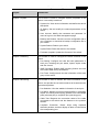
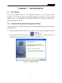
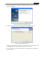
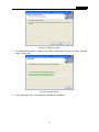
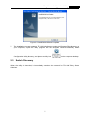
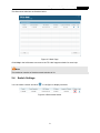
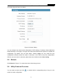
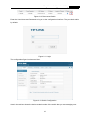
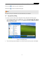
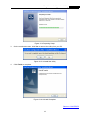
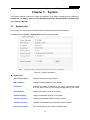
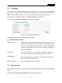
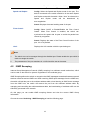
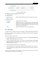
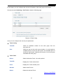
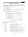
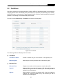
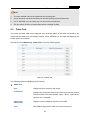
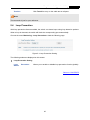
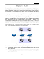
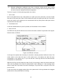
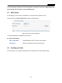
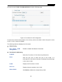
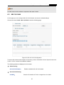
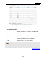
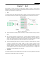
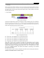
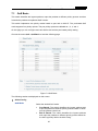
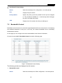
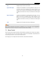
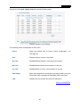
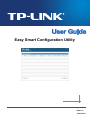
Easy Smart Configuration Utility REV1.1.0 1910010977 CONTENTS Chapter 1 About this Guide.................................................................................1 1.1 Intended Readers ...................................................................................................... 1 1.2 Conventions............................................................................................................... 1 1.3 Overview of This Guide ............................................................................................. 1 Chapter 2 Getting Started....................................................................................4 2.1 Introduction................................................................................................................ 4 2.2 Install the Easy Smart Configuration Utility ............................................................... 4 2.3 Switch Discovery ....................................................................................................... 7 2.4 Switch Settings .......................................................................................................... 8 2.5 Refresh ...................................................................................................................... 9 2.6 Utility Features Overview........................................................................................... 9 2.7 Uninstall the Utility ................................................................................................... 11 Chapter 3 System...............................................................................................13 3.1 System Info.............................................................................................................. 13 3.2 IP Setting ................................................................................................................. 14 3.3 User Account ........................................................................................................... 14 3.4 Backup and Restore ................................................................................................ 15 3.5 System Reboot ........................................................................................................ 16 3.6 System Reset .......................................................................................................... 16 3.7 Firmware Upgrade................................................................................................... 17 Chapter 4 Switching...........................................................................................18 4.1 Port Setting.............................................................................................................. 18 4.2 IGMP Snooping ....................................................................................................... 19 4.3 Port Trunk................................................................................................................ 20 Chapter 5 Monitoring .........................................................................................22 5.1 Port Statistics........................................................................................................... 22 5.2 Port Mirror................................................................................................................ 23 5.3 Cable Test ............................................................................................................... 24 5.4 Loop Prevention ...................................................................................................... 25 Chapter 6 VLAN..................................................................................................26 6.1 MTU VLAN .............................................................................................................. 28 6.2 Port Based VLAN .................................................................................................... 28 I 6.3 802.1Q VLAN .......................................................................................................... 30 6.4 802.1Q PVID Setting ............................................................................................... 31 Chapter 7 QoS ....................................................................................................33 7.1 QoS Basic................................................................................................................ 35 7.2 Bandwidth Control ................................................................................................... 36 7.3 Storm Control .......................................................................................................... 37 Chapter 8 Help....................................................................................................39 8.1 Help ......................................................................................................................... 39 8.2 About ....................................................................................................................... 39 II Easy Smart Configuration Utility User Guide Chapter 1 About this Guide This User Guide contains information for setup and guidance of the Easy Smart Configuration Utility. Please read this guide carefully before operation. 1.1 Intended Readers This Guide is intended for network managers familiar with IT concepts and network terminologies. 1.2 Conventions In this Guide the following conventions are used: Menu Name→Submenu Name indicates the menu structure. System→System Info→System Summary means the System Summary page under the System Info menu option located under the System menu. Bold font indicates a button, a toolbar icon, menu or menu item. Symbols in this guide: Symbol 1.3 Description Note: Ignoring this type of note might result in a malfunction or damage to the device. Tips: This format indicates important information that helps you make better use of your device. Overview of This Guide Chapter Introduction Chapter 1 About This Guide Introduces the guide structure and conventions. Chapter 2 Getting Started Introduces the installation and uninstallation of the utility, and the overview of its interface. 1 Easy Smart Configuration Utility User Guide Chapter Introduction Chapter 3 System This module is used to configure system properties of the switch. Here mainly introduces: Chapter 4 Switching Chapter 5 Monitoring System Info: View device information and define the device description. IP Setting: Get and modify the network parameters of the switch. User Account: Modify the username and password for users to log on to the Web management page. Backup and Restore: Save the current configuration file to your computer or download a backup configuration file to your switch. System Reboot: Reboot your switch. System Reset: Reset the switch to the default. Firmware Upgrade: Update the firmware of the switch. This module is used to configure the basic functions of the switch. Port Setting: Configure and view the basic parameters of each port, including the port status, speed, duplex mode and flow control. IGMP Snooping: Enable IGMP snooping feature and view the current IGMP Group information. Port Trunk: Configure and view the information of the trunk group of the switch. This module is used to monitor the traffic information of the switch, and provide the convenient method to locate and solve the network problem. Port Statistics: View the statistic information of each port. Port Mirror: Monitor and mirror network traffic by forwarding copies of incoming and outgoing packets from one/multiple ports (mirrored port) to a specific port (mirroring port). Cable Test: Diagnose the connection status of the cable connected to the switch and the distance to the problem location. Loopback Prevention: Detect loops using loopback detection packets, and then display an alert or further block the corresponding port. 2 Easy Smart Configuration Utility User Guide Chapter Introduction Chapter 6 VLAN This module is used to configure VLANs to control broadcast in LANs. Here mainly introduces: Chapter 7 QoS This module is used to configure QoS function to provide different quality of service for various network applications and requirements. Here mainly introduces: Chapter 8 Help MTU VLAN: Set the MTU VLAN mode. Port Based VLAN: Set the Port-Based VLAN mode 802.1Q VLAN: Set the 802.1Q Tag VLAN mode. 802.1Q PVID Setting: Configure 802.1Q PVID value. QoS Basic: Configure and view the basic parameters of QoS. Bandwidth Control: Configure and view the bandwidth control function information. Storm Control: Configure and view the storm control function information. Lists the help and version information of the utility. Return to CONTENTS 3 Easy Smart Configuration Utility User Guide Chapter 2 2.1 Getting Started Introduction Easy Smart Configuration Utility is the management software for the TP-LINK Easy Smart Switches. The utility allows operators to centrally manage entire networks of the Easy Smart Switches, such as TL-SG108E/TL-SG1016DE/TL-SG1024DE. We will take TL-SG108E for example throughout this Guide. 2.2 Install the Easy Smart Configuration Utility If an earlier version of the utility is present on your computer, please install this version to replace the older version. 1. Insert the provided Resource CD that came with your switch into your CD-ROM drive. Open the file folder and double click the icon . Please wait for the InstallShield Wizard preparing the setup shown as the following screen. Figure 2-1 Preparing to Install 4 Easy Smart Configuration Utility User Guide 2. Then the following screen will appear. Click Next to continue. If you want to stop the installation, click Cancel. Figure 2-2 Welcome to the InstallShield Wizard 3. Choose the destination location for the installation files and click Next to continue. Figure 2-3 Choose Destination Location By default, the installation files are saved on the Program Files folder of system disk. Click the Change button to modify the destination location proper to your need. 4. Till now, The Wizard is ready to begin the installation. Click Install to start the installation on the following screen. 5 Easy Smart Configuration Utility User Guide Figure 2-4 Install the Utility 5. The InstallShield Wizard is installing Easy Smart Configuration Utility shown as the following screen. Please wait. Figure 2-5 Setup Status 6. On the following screen, click Finish to complete the installation. 6 Easy Smart Configuration Utility User Guide Figure 2-6 InstallShield Wizard Complete 7. The installation process creates a TP-LINK subdirectory under the \Program Files directory on your computer, copies the utility program into the \Program Files\TP-LINK\Easy Smart Configuration Utility directory, and places a utility icon 2.3 on the computer desktop. Switch Discovery When the utility is launched, it immediately searches the network for TP-LINK Easy Smart Switches. 7 Easy Smart Configuration Utility User Guide The discovered switches are listed as below. Figure 2-7 Main Page Click Help in the left bottom to access to the TP-LINK support website for more help. Note: The maximum number of the discovered switches is 30. 2.4 Switch Settings You can select a switch and click to configure or display its status. Figure 2-8 Discovered Switch 8 Easy Smart Configuration Utility User Guide The setting figure will shown as below: Figure 2-9 Switch Setting You can configure the switch’s Device Description, DHCP Setting, IP Address, Subnet Mask and Default Gateway on this page. The login User Name and Password are required to complete the configuration. By default, they are both admin. Clicking Apply can only make the new configurations effective before the switch is rebooted. If you want to keep the configurations effective even the switch is rebooted, please select the checkbox behind Save Config. 2.5 Refresh Click Refresh in Figure 2-7 to restart the switch discovering process. 2.6 Utility Features Overview You can select a switch and click or double click its corresponding entry to log on to the switch for further configuration. 9 Easy Smart Configuration Utility User Guide Figure 2-10 Discovered Switch Enter the User Name and Password to log on to the configuration interface. They are both admin by default. Figure 2-11 Login The configuration figure is shown as blow: Figure 2-12 Switch Configuration Area in the red box shows the device model number of the switch that you are managing now. 10 Easy Smart Configuration Utility User Guide Click the icon to save the current configurations. Click the icon to return to the discovering page. Note: The switch you log on to should be in the same subnet with your computer. 2.7 Uninstall the Utility If you want to remove the Easy Smart Configuration Utility, please take the following steps: 1. On the Windows taskbar, click the Start button, point to All ProgramsTP-LINK Easy Smart Configuration Utility, and then click Uninstall Easy Smart Configuration Utility, shown as the following figure. Figure 2-13 Preparing Setup 2. Then the following screen will appear. If you want to stop the remove process, click Cancel. 11 Easy Smart Configuration Utility User Guide Figure 2-14 Preparing Setup 3. On the continued screen, click Yes to remove the utility from your PC. Figure 2-15 Uninstall the Utility 4. Click Finish to complete. Figure 2-16 Uninstall Complete Return to CONTENTS 12 Easy Smart Configuration Utility User Guide Chapter 3 System The System module is mainly for system configuration of the switch, including seven submenus: System Info, IP Setting, User Account, Backup and Restore, System Reboot, System Reset and Firmware Upgrade. 3.1 System Info On this page you can view the system information and define the device description. Choose the menu System→System Info to load the following page. Figure 3-1 System Information System Info Device Description: Displays the device model number. MAC Address: Displays the MAC address of the switch. IP Address: Displays the system IP address of the switch. The default system IP is 192.168.0.1 and you can change it appropriate to your needs. Subnet Mask: Displays the subnet mask of the switch. Default Gateway: Displays the default gateway of the switch. Firmware Version: Displays the installed software version number. Hardware Version: Displays the installed device hardware version number. Device Description: Give a description to the device for identification. 13 Easy Smart Configuration Utility User Guide 3.2 IP Setting Each device in the network possesses a unique IP address. You can log on to the IP Setting page to operate the switch using this IP address. The switch supports the DCHP mode to obtain an IP address. The IP address obtained using a new mode will replace the original IP address. On this page you can get and modify the network parameters of the switch. Choose the menu System→IP Setting to load the following page. Figure 3-2 System IP Address Setting The following entries are displayed on this screen: System IP Address Setting DHCP Setting: Allows you to enable or disable the switch to serve as DHCP client. If DHCP client is enabled, the switch will obtain the IP address, subnet Mask and default gateway from the DHCP Server automatically; otherwise, these three items should be configured manually. By default, it is disabled. IP Address: Enter the system IP of the switch. The default system IP is 192.168.0.1 and you can change it appropriate to your needs. Subnet Mask: Enter the subnet mask of the switch. By default, the switch uses 255.255.255.0 as the subnet mask. Default Gateway: 3.3 Enter the default gateway of the switch. User Account On this page you can modify the administrator’s username and password in order to refuse illegal users. Choose the menu System→User Account to load the following page. 14 Easy Smart Configuration Utility User Guide Figure 3-3 System User Setting The following entries are displayed on this screen: System User Setting User Name: Create a name for administrator’s login. Old Password: Type the old password. Password: Type a new password for administrator’s login. Confirm Password: Retype the new password. Note: 1. The length of user name and password should not be more than 16 characters using digits, letters and underlines only. 2. The default username/password is admin/admin. 3.4 Backup and Restore On this page you can download the current configuration and save it as a file to your computer, or upload a backup configuration file to restore your switch to this previous configuration. Choose the menu System→Backup and Restore to load the following page. Figure 3-4 System Config Backup 15 Easy Smart Configuration Utility User Guide The following entries are displayed on this screen: System Config Backup Backup Config: Click the Backup Config button to save the current configuration as a file to your computer. You are suggested to take this measure before upgrading. System Config Restore Restore Config: Click the Choose File button to select the backup configuration file, then click the Restore Config button. It will take effect after the switch automatically reboots. Note: 1. It will take a few minutes to backup the configuration. Please wait without any operation. 2. It will take a few minutes to restore the configuration. Please wait without any operation. 3. To avoid any damage, please don’t power down the switch while being restored. 4. After being restored, the current settings of the switch will be lost. Wrong uploaded configuration file may cause the switch unmanaged. 3.5 System Reboot On this page you can reboot the switch and return to the login page. Please save the current configuration before rebooting to avoid losing the configuration unsaved. Choose the menu System→System Reboot to load the following page. Figure 3-5 System Reboot Note: To avoid damage, please don't turn off the device while rebooting. 3.6 System Reset On this page you can reset the switch to the default. All the settings will be cleared after the switch is reset. 16 Easy Smart Configuration Utility User Guide Choose the menu System→System Reset to load the following page. Figure 3-6 System Reset Note: After the system is reset, the switch will be reset to the default and all the settings will be cleared. 3.7 Firmware Upgrade The switch system can be upgraded via this management page. To upgrade the system is to get more functions and better performance. Go to http://www.tp-link.com to download the updated firmware. Choose the menu System→Firmware Upgrade to load the following page. Figure 3-7 System Upgrade Note: 1. Don’t interrupt the upgrade. 2. Please select the proper software version matching with your hardware to upgrade. 3. To avoid damage, please don't turn off the device while upgrading. 4. After upgrading, the device will reboot automatically. 5. You are suggested to backup the configuration before upgrading. Return to CONTENTS 17 Easy Smart Configuration Utility User Guide Chapter 4 Switching Switching module is used to configure the basic functions of the switch, including three submenus: Port Setting, IGMP Snooping and Port Trunk. 4.1 Port Setting On this page, you can configure the basic parameters for the ports. When the port is disabled, the packets on the port will be discarded. Disabling the port which is vacant for a long time can reduce the power consumption effectively. And you can enable the port when it is in need. The parameters will affect the working mode of the port, please set the parameters appropriate to your needs. Choose the menu Switching→Port Setting to load the following page. Figure 4-1 Port Config The following entries are displayed on this screen. Port Config Select: Select the desired port for configuration. It is multi-optional. Port: Displays the port number. Status: Allows you to Enable/Disable the port. When Enable is selected, the port can forward the packets normally. 18 Easy Smart Configuration Utility User Guide Speed and Duplex: Config: Select the Speed and Duplex mode for the port. The device connected to the switch should be in the same Speed and Duplex mode with the switch. When “Auto” is selected, the Speed and Duplex mode will be determined by auto-negotiation. Actual: Displays the actual working state of the port. Flow Control: Config: Select On/Off to Enable/Disable the Flow Control feature. When Flow Control is enabled, the switch can synchronize the speed with its peer to avoid the packet loss caused by congestion. Actual: Displays the state of the Flow Control function of the port. It is off by default. LAG: Displays the LAG number which the port belongs to. Note: 1. The switch can not be managed through the disabled port. Please enable the port which is used to manage the switch. 2. The parameters of the port members in a LAG should be set as the same. 4.2 IGMP Snooping Internet Group Management Protocol (IGMP) snooping is a multicast control mechanism, which can be used on the switch for dynamic registration of the multicast group. IGMP Snooping allows the switch to recognize the IGMP messages transmitted between network stations or devices and an IGMP host. When receiving IGMP report message from the IGMP host, the switch will add the port to the multicast address table; when listening to IGMP leave message from the IGMP host, the switch will remove the port from the multicast address table. By managing and controlling the multicast address table, the broadcasting of multicast traffic can be effectively prevented in the network. On this page you can enable IGMP snooping feature and view the current IGMP Group information. Choose the menu Switching→IGMP Snooping to load the following page. 19 Easy Smart Configuration Utility User Guide Figure 4-2 IGMP Snooping The following entries are displayed on this screen: IGMP Snooping IGMP Snooping: 4.3 Enable or disable IGMP snooping function globally on the switch. Multicast IP Table IP Address: Displays the multicast IP address. VLAN ID: Displays the VLAN ID of the multicast group. If the packet does not carry VLAN ID, then here displays the PVID of the port. All port members of a multicast group should be divided to the same VLAN, and have the same PVID. Ports: Displays the forwarding port list of the multicast group. Port Trunk Port trunk is used to combine a number of ports together to make a single high-bandwidth data path, which can highly extend the bandwidth. The bandwidth of the trunk is the sum of bandwidth of its member ports. There are some rules on using trunk: For the member ports in a trunk group, their configuration of Port setting (Speed and Duplex, Flow Control), QoS must be the same. For the newly joined member ports in a trunk group, their default setting of Port setting (Speed and Duplex, Flow Control), QoS will be configured the same as that of the first member port in the trunk group. The trunk member ports cannot be set as mirroring port. Before setting the trunk, its member ports should be divided to the same VLAN, and have the same PVID and drop the untagged packet rule. Change of the trunk setting will not affect the VLAN setting. If the port trunk is needed, you are suggested to configure the port trunk function here before configuring the other functions for the member ports. 20 Easy Smart Configuration Utility User Guide On this page, you can configure and view the information of the trunk group of the switch. Choose the menu Switching→Port Trunk to load the following page. Figure 4-3 Trunk Config Here you can configure and view the port parameters. Trunk Config Trunk ID: Select an identified number for the trunk group from the drop-down list. Port: Select the port as the trunk group member. It is multi-optional. Available ports of trunk1 are port1-port4, and available ports of trunk2 are port5-port8. Clearing all the ports of the trunk group will delete this trunk group. Trunk Table Select: Select the desired Trunk. It is multi-optional. Trunk ID: Displays the Trunk number here. Ports: Displays the Trunk member ports. SlectAll: Select all the Trunks. Delete: Delete the selected Trunk. Return to CONTENTS 21 Easy Smart Configuration Utility User Guide Chapter 5 Monitoring Monitoring module monitors the traffic information of the switch, and provides the convenient method to locate and solve the network problem, includes four submenus: Port Statistics, Port Mirror, Cable Test and Loop Prevention. 5.1 Port Statistics On this page you can view the statistic information of each port, which facilitates you to monitor the traffic and locate faults promptly. Choose the menu Monitoring→Port Statistics to load the following page. Figure 5-1 Port Statistics The following entries are displayed on this screen: Port Statistics Port: Displays the port number of the switch. Status: Displays whether the port is enabled or disabled. Link Status: Displays the link state of the port. TxGoodPkt: Displays the number of good packets transmitted on the port. The error packets are not counted in. TxBadPkt: Displays the number of error packets transmitted on the port. RxGoodPkt: Displays the number of good packets received on the port. The error packets are not counted in. RxBadPkt: Displays the number of error packets received on the port. 22 Easy Smart Configuration Utility User Guide 5.2 Port Mirror Port mirror function is to monitor and mirror network traffic by forwarding copies of incoming and outgoing packets from one/multiple ports (mirrored port) to a specific port (mirroring port). Usually, the mirroring port is connected to a data diagnosis device, which is used to analyze the mirrored packets for monitoring and troubleshooting the network. Choose the menu Monitoring→Port Mirror to load the following page. Figure 5-2 Port Mirror The following entries are displayed on this screen: Port Mirror Port Mirror Status: Enable or disable the port mirror feature of the specified port. Mirroring Port: Select a port from the pull-down list as the mirroring port. Mirrored Port Mirrored Port: Displays the number of mirrored port to monitor the traffic. Ingress: Select whether to monitor the ingress traffic. When the ingress is enabled, the ingress traffic received by the mirrored port will be copied to the mirroring port. Egress: Select whether to monitor the egress traffic. When the egress is enabled, the outgoing packets sent by the mirrored port will be copied to the mirroring port. 23 Easy Smart Configuration Utility User Guide Note: 1. The trunk member cannot be selected as the mirroring port. 2. A port cannot be set as the mirrored port and the mirroring port simultaneously. 3. For TL-SG108E, you can select only one port as the mirrored port. 4. The port mirror function can take effect span the multiple VLANs. 5.3 Cable Test This switch provides cable test to diagnose the connection status of the cable connected to the switch and the distance to the problem location, which facilitates you to locate and diagnose the trouble spot of the network. Choose the menu Monitoring→Cable Test to load the following page. Figure 5-3 Cable Test The following entries are displayed on this screen: Cable Test Port: Displays the port number of the switch. Test Result: Displays the connection status of the cable connected to the port. The test results of the cable include “Open”, “Short”, ”Open Short”, “Normal” and “Crosstalk”. Cable Fault Distance(m): Displays the error length (in meters) of the cable. Test: Click Test to diagnose the cable connected to this port. 24 Easy Smart Configuration Utility User Guide Test ALL: Click Test All to carry on the cable test on all ports. Note: The test result is just for your reference. 5.4 Loop Prevention With loop prevention feature enabled, the switch can detect loops using loop detection packets. When a loop is detected, the switch will block the corresponding port automatically. Choose the menu Monitoring→Loop Prevention to load the following page. Figure 5-4 Loop Prevention Setting The following entries are displayed on this screen: Loop Prevention Setting Loop Status: Prevention Allows you to enable or disable loop prevention function globally. Return to CONTENTS 25 Easy Smart Configuration Utility User Guide Chapter 6 VLAN The traditional Ethernet is a data network communication technology based on CSMA/CD (Carrier Sense Multiple Access/Collision Detect) via shared communication medium. Through the traditional Ethernet, the overfull hosts in LAN will result in serious collision, flooding broadcasts, poor performance or even breakdown of the Internet. Though connecting the LANs through switches can avoid the serious collision, the flooding broadcasts cannot be prevented, which will occupy plenty of bandwidth resources, causing potential serious security problems. A Virtual Local Area Network (VLAN) is a network topology configured according to a logical scheme rather than the physical layout. The VLAN technology is developed for switches to control broadcast in LANs. By creating VLANs in a physical LAN, you can divide the LAN into multiple logical LANs, each of which has a broadcast domain of its own. Hosts in the same VLAN communicate with one another as if they are in a LAN. However, hosts in different VLANs cannot communicate with one another directly. Therefore, broadcast packets are limited in a VLAN. Hosts in the same VLAN communicate with one another via Ethernet whereas hosts in different VLANs communicate with one another through the Internet devices such as router, the Lay3 switch, etc. The following figure illustrates a VLAN implementation. Figure 6-1 VLAN Implementation Compared with the traditional Ethernet, VLAN enjoys the following advantages. (1) Broadcasts are confined to VLANs. This decreases bandwidth utilization and improves network performance. (2) Network security is improved. VLANs cannot communicate with one another directly. That is, a host in a VLAN cannot access resources in another VLAN directly, unless routers or Layer 3 switches are used. 26 Easy Smart Configuration Utility User Guide (3) Network configuration workload for the host is reduced. VLAN can be used to group specific hosts. When the physical position of a host changes within the range of the VLAN, you do not need to change its network configuration. There are 3 types of VLAN modes supported in the switch: 1. MTU VLAN MTU VLAN (Multi-Tenant Unit VLAN) defines an uplink port which will build up several VLANs with each of the other ports. Each VLAN contains two ports, the uplink port and one of the other ports in the switch, so the uplink port can communicate with any other port but other ports cannot communicate with each other. 2. Port Based VLAN VLANs are divided based on ports. By default, the Port Based VLAN is enabled. 3. 802.1Q VLAN The IEEE 802.1Q protocol defines a new format of the frame; it adds a Tag header in the original Ethernet frame, as follows: Figure 6-2 IEEE 802.1Q Frame VLAN tags in the packets are necessary for the switch to identify packets of different VLANs. The switch works at the data link layer in OSI model and it can identify the data link layer encapsulation of the packet only, so you can add the VLAN tag field into the data link layer encapsulation for identification. IEEE 802.1Q Tag VLAN is divided by VLAN ID (VID). On receiving a frame, the switch checks the VID in the Tag header of the frame to decide which VLAN it belongs to. If the receiving frame doesn’t contain the Tag header, the switch will assign a Tag to the frame, using the PVID of the port as its VID. In this User Guide, the tagged packet refers to the packet with VLAN tag whereas the untagged packet refers to the packet without VLAN tag. 27 Easy Smart Configuration Utility User Guide The VLAN module is mainly for VLAN configuration, including four submenus: MTU VLAN, Port Based VLAN, 802.1Q VLAN and 802.1Q PVID Setting. 6.1 MTU VLAN On this page you can choose to enable MTU VLAN mode and configure VLANs. Choose the menu VLAN→MTU VLAN to load the following page. Figure 6-3 MTU VLAN Configuration The following entries are displayed on this screen: 6.2 MTU VLAN Setting MTU VLAN Status: Enable/Disable the MTU VLAN function globally. Uplink Port: Select the uplink port from the pull-down list. Port Based VLAN On this page you can configure Port Based VLAN feature and view the related settings. 28 Easy Smart Configuration Utility User Guide Choose the menu VLAN→Port Based VLAN to load the following page. Figure 6-4 Port Based VLAN Configuration To ensure the normal communication of the factory switch, the default VLAN of all ports is set to VLAN1. VLAN 1 cannot be deleted. The following entries are displayed on this screen: Global Config Port Based VLAN Configuration: Enable or disable Port Based VLAN mode. Port Based VLAN Setting VLAN ID: Ports: Select the ID number of VLAN from the pull-down list. Click the port icon to select the port of the VLAN. It is multi-optional. If this field is selected, it indicates the port belongs to the current VLAN. VLAN: Port List: Delete VLAN: Displays the ID number of VLAN. Displays the port members in the VLAN. Click Delete to delete the corresponding VLAN. 29 Easy Smart Configuration Utility User Guide Note: A VLAN cannot be the subset or superset of the other VLANs. 6.3 802.1Q VLAN On this page you can configure 802.1Q VLAN feature and view the related settings. Choose the menu VLAN→802.1Q VLAN to load the following page. Figure 6-5 802.1Q VLAN Configuration To ensure the normal communication of the factory switch, the default VLAN of all ports is set to be VLAN1. VLAN 1 cannot be modified or deleted. The following entries are displayed on this screen: Global Config 802.1Q VLAN Status: Enable or disable 802.1Q VLAN mode. 802.1Q VLAN Setting VLAN ID: Enter the ID number of VLAN. It ranges from 2 to 4094. 30 Easy Smart Configuration Utility User Guide VLAN Name: Give a name to the VLAN for identification. Untagged Ports: Click the port icon to configure the egress rule of the traffic on this port as untagged. The switch drops the tag header before sending the packet. Tagged Ports: Click the port icon to configure the egress rule of the traffic on this port as tagged. The switch adds the tag header before sending the packet. 6.4 VLAN ID: Displays the ID number of VLAN. VLAN Name: Displays the user-defined name of VLAN. Member Ports: Displays the port members in the VLAN. Tagged Ports: Displays the tagged port members in the VLAN. Untagged Ports: Displays the untagged port members in the VLAN. Delete VLAN: Click Delete to delete the corresponding VLAN. 802.1Q PVID Setting PVID (Port Vlan ID) is the default VID of the port. When the switch receives an un-VLAN-tagged packet, it will add a VLAN tag to the packet according to the PVID of its received port and forward the packets. When creating VLANs, the PVID of each port, indicating the default VLAN to which the port belongs, is an important parameter with the following two purposes: (1) When the switch receives an un-VLAN-tagged packet, it will add a VLAN tag to the packet according to the PVID of its received port (2) PVID determines the default broadcast domain of the port, i.e. when the port receives UL packets or broadcast packets, the port will broadcast the packets in its default VLAN. On this page you can configure PVID of the specified port. By default, the PVID of all ports is 1. Choose the menu VLAN→802.1Q VLAN PVID Setting to load the following page. 31 Easy Smart Configuration Utility User Guide Figure 6-6 802.1Q VLAN PVID Setting The following entries are displayed on this screen: 802.1Q VLAN PVID Setting Select: Select the desired port for configuration. It is multi-optional. Port: Displays the port number. PVID: Enter a PVID number for the port. When adding the tag header to the received untagged packet, the switch will automatically uses this PVID value as the VLAN ID of the added tag. LAG: Displays the LAG to which the port belongs. Note: 1. 802.1Q VLAN should be enabled before setting PVID. 2. You can go to Switching→Port Trunk page to configure the LAG status of the port. Return to CONTENTS 32 Easy Smart Configuration Utility User Guide Chapter 7 QoS QoS (Quality of Service) functions to provide different quality of service for various network applications and requirements and optimize the bandwidth resource distribution so as to provide a network service experience of a better quality. QoS This switch classifies the ingress packets, maps the packets to four different priority queues and then forwards the packets according to WRR scheduling algorithms to implement QoS function. Figure 7-1 QoS Function Traffic classification: Identifies packets conforming to certain characters according to certain rules. Map: This switch supports four priority queues. The priority queues are labeled as 1(Lowest), 2(Normal), 3(Medium) and 4(Highest), among them the bigger the value, the higher the priority. The ingress packets are mapped to four different priority queues based on the QoS modes. This switch implements two QoS modes based on port and on 802.1P. Queue scheduling algorithm: When the network is congested, the problem that many packets compete for resources must be solved, usually in the way of queue scheduling. In both port-based and 802.1P QoS modes, this switch adopts WRR scheduling algorithm. In WRR scheduling algorithm, packets in all the queues are sent in order based on the weight value for each queue and every queue can be assured of a certain service time. The weight value indicates the occupied proportion of the resource. QoS Mode This switch implements two QoS modes based on port and on 802.1P. By default, the QoS mode based on port is enabled and the other one is optional. 33 Easy Smart Configuration Utility User Guide 1. Port Based When port-base QoS mode is enabled, the user can manually map the ingress packets of the port to four different priority queues. After that, the switch will preferentially send packets in the queue with higher priority, and only when the queue with higher priority is empty, packets in the queue with lower priority are sent. 2. 802.1P Based Figure 7-2 802.1Q Frame As shown in the figure above, each 802.1Q Tag has a Pri field, comprising 3 bits. The 3-bit priority field is 802.1p priority in the range of 0 to 7. The 802.1p priority value determines how the switch maps the ingress packets to the priority queues. The mapping relationship between eight 802.1p priority value and priority queues is shown as follows: Figure 7-3 Map 802.1P Priority Priority 0 and 1 are assigned to the 1 (Lowest) priority queue. Priority 2 and 3 are assigned to the 2 (Normal) priority queue. Priority 4 and 5 are assigned to the 3 (Medium) priority queue. Priority 6 and 7 are assigned to the 4 (Highest) priority queue. When 802.1P QoS mode is enabled, the switch will automatically map the ingress packets to priority queues based on the 802.1p priority and the above mapping relationship. After that, packets in all the queues are sent in order based on the weight value for each queue. The weight value ratio of TC0, TC1, TC2 and TC3 is 1:2:4:8. As for the untagged packets, the switch will forward it according to the default port-based QoS mode. The QoS module is mainly for priority configuration and traffic control, including three submenus: QoS Basic, Bandwidth Control and Storm Control. 34 Easy Smart Configuration Utility User Guide 7.1 QoS Basic This switch classifies the ingress packets, maps the packets to different priority queues and then forwards the packets to implement QoS function. This switch implements two priority modes based on port and on 802.1P. The port-based QoS mode supports four priority queues. The port priority queues are labeled as 1, 2, 3, and 4. On this page you can configure and view QoS mode and the port-based priority setting. Choose the menu QoS→QoS Basic to load the following page. Figure 7-4 QoS Basic The following entries are displayed on this screen: Global Config QoS Mode: Select the desired QoS mode. Port Based: The switch classifies the ingress packets and maps the packets to different priority queues based on which port the packets come from. 802.1P Based: The switch classifies the ingress packets and maps the packets to different priority queues based on the 802.1p priority field in the 802.1Q tag. 35 Easy Smart Configuration Utility User Guide 7.2 Port Based Priority Setting Select: Select the desired port for configuration. It is multi-optional. Port: Displays the port number. Priority Queue: Specify the priority queue the packets from the port are mapped to. The priorities are labeled as 1~4 and among them the bigger the value, the higher the priority. LAG: Displays the LAG number which the port belongs to. Bandwidth Control Bandwidth control functions to control the ingress/egress traffic rate on each port via configuring the available bandwidth of each port. In this way, the network bandwidth can be reasonably distributed and utilized. On this page you can configure and view the bandwidth control function information. Choose the menu QoS→Bandwidth Control to load the following page. Figure 7-5 Bandwidth Control Setting The following entries are displayed on this screen: Bandwidth Control Select: Select the desired port for Rate configuration. It is multi-optional. 36 Easy Smart Configuration Utility User Guide Port: Displays the port number of the switch. Ingress Rate (bps): Configure the bandwidth for receiving packets on the port. You can select a rate from the dropdown list or select "Manual" to set Ingress rate, the system will automatically select integral multiple of 64Kbps that closest to the rate you entered as the real Ingress rate. Egress Rate(bps): Configure the bandwidth for sending packets on the port. You can select a rate from the dropdown list or select "Manual" to set Egress rate, the system will automatically select integral multiple of 64Kbps that closest to the rate you entered as the real Egress rate. LAG: Displays the LAG number which the port belongs to. Note: When egress bandwidth control feature is enabled for one or more ports, you are suggested to disable the flow control on each port to ensure the switch works normally. 7.3 Storm Control Storm Control function allows the switch to filter broadcast, multicast and UL frame in the network. If the transmission rate of the three kind packets exceeds the set bandwidth, the packets will be automatically discarded to avoid network broadcast storm. On this page you can configure and view the storm control function information. 37 Easy Smart Configuration Utility User Guide Choose the menu QoS→Storm Control to load the following page. Figure 7-6 Storm Control Setting The following entries are displayed on this screen: Select: Select the desired port for Storm Control configuration. It is multi-optional. Port: Displays the port number of the switch. Bc Limit: Enable/Disable broadcast control feature for the port. Mc Limit: Enable/Disable multicast control feature for the port. UL Limit: Enable/Disable UL-Frame control feature for the port. Rate (Kbps): Select the bandwidth for receiving the specified packet on the port. The packet traffic exceeding the bandwidth will be discarded. LAG: Displays the LAG number which the port belongs to. Return to CONTENTS 38 Easy Smart Configuration Utility User Guide Chapter 8 Help This page contains two submenus: Help and About. 8.1 Help Choose the menu Help→Help to load the following page. Figure 8-1 Help Click Online Help to access to the TP-LINK support website and to the online user guide for the Easy Smart Configuration Utility (the latest copy of this manual). 8.2 About To view the utility software version, choose the menu Help→About. Figure 8-2 Software Version Return to CONTENTS 39