1
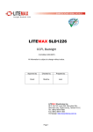
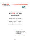
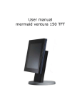
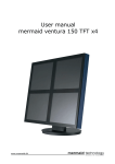
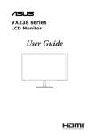
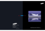
LCD-2001VB Sunlight Readable 20.1" LCD Display (1st Edition 11/25/2004 ) All information is subject to change without notice. R 1319 Dexter Avenue N.#020, Seattle,WA 98109 TEL206-623-6000 FAX206-623-6609 Page 1 Content Introduction........................................................................................................... 3 Hardware Installation............................................................................................ 3 The Display Timing............................................................................................... 5 The Display Outline Dimensions.......................................................................... 6 The Display Controls ............................................................................................ 7 The Screen Adjustment ........................................................................................ 8 Quick Installation &Troubleshooting Tips ........................................................... 19 Specification ........................................................................................................20 Product Safety Precautions ................................................................................ 21 22 Page 2 Introduction Welcome to enjoy the fantastic sightseeing world. This new technology will bring you the whole new feeling about the “monitor”. We show here some of the major advantages of the LCD monitor. You will really find some other advantages when you use it. Hardware Installation This chapter will guide you the correct installation procedures of your LCD monitor. Unpacking After you unpack your LCD Monitor, please make sure that the following items are included in the carton and in good condition. If you find that any of these items are damaged or missing, please contact your dealer immediately. One LCD Monitor 15-pin D-sub VGA cable AC/DC adapter with 12V DC output & AC power cord Remote Control TV Tuner (Option) Installation This analog LCD display does not require any special drivers. Necessary drivers are supplied by the video card manufacturer and may be found on the diskettes supplied with the video card that came with your computer. Windows 98/2000/XP drivers for both the display and the video card are supplied on the Windows 98/2000/XP CD or diskettes. Unfortunately, Microsoft did not provide a complete listing of the displays on the initial retail release. You may use the standard XGA (1024x768) as the display type. The video card must also be set up correctly in Windows 98/2000/XP and make sure the video output of the VGA card is on list in Section 6.1 or check your Video Card manual or Windows 98/2000/XP Read me file for further information on Video Card. After the question listed above is solved, we continue the setup procedure as below. 1. 2. 3. 4. 5. 6. Turn power off both Computer and Display before making any connection. Install Display on the solid horizontal surface such as a table or desk. Connect the power cable and the AC/DC adapter, then connect adapter toe the back of the LCD monitor. The LCD monitor comes with a 15-pin video cable; you may use this cable for both IBM PC’s & compatibles and Macintosh. Tighten the screws of the Display cable until the connectors are fastened securely. Switch on power to the Computer system, then to the monitor. Page 3 The following picture provides the connection outline AV in S-video VGA AV Audio in Audio in TV Tuner DC Power in VGA Input Pin Assignment This section describes the pin assignment of the LCD’s VGA connector. It is called 15pin Mini D-sub connector. 10 Pin No. 1 2 3 4 5 6 7 8 9 10 11 12 13 14 15 5 1 15 11 Signal Connector Red Video Signal Green Video Signal Blue Video Signal N.C. Ground Ground for red video signal Ground for green video signal Ground for blue video signal N.C. Ground N.C. DDC data Horizontal sync signal Vertical sync signal DDC clock Page 4 6 The Display Timing Applicable video timing The following table lists the better display quality modes that the LCD monitor provides. If the other video modes are input, the monitor will stop working or display unsatisfactory picture quality. VESA Modes Mode Resolution Total Nominal Frequency ±0.5KHz Nominal Frequency ±0.5KHz Nominal Pixel Clock (MHz) DOS 720x400@70Hz 900x449 31.469 70.087 28.322 VGA 640x480@60Hz 800x525 31.469 59.940 25.175 640x480@72Hz 832x520 37.861 72.809 31.500 640x480@75Hz 840x500 37.500 75.000 31.500 800x600@56Hz 1024x625 35.156 56.250 36.000 800x600@60Hz 1056x628 37.879 60.017 40.000 800x600@72Hz 1040x666 48.077 72.188 50.000 800x600@75Hz 1056x625 46.875 75.000 49.500 1024x768@60Hz 1344x804 48.363 60.004 65.000 1024x768@70Hz 1328x806 56.476 70.069 75.000 1024x768@75Hz 1312x800 60.023 75.029 78.750 SVGA XGA IBM Modes EGA 640x350@70Hz 800x449 31.469 70.086 25.175 DOS 720x400@70Hz 900x449 31.469 70.087 28.322 VGA 640x480@60Hz 800x525 31.469 75.000 31.500 XGA 1024x768@72Hz 1304x798 57.515 72.100 75.000 MAC Modes VGA 640x480@60Hz 800x525 31.469 59.940 25.175 SVGA 832x624@75Hz 1152x667 49.725 74.551 57.2832 XGA 1024x768@75Hz 1328x804 60.927 74.927 80.000 Page 5 The Display Outline Dimensions Unit: mm Page 6 The Display Controls Contro l F u nction Side Membrane Control Button Œ Power Key : Power ON/Off. • Power LED : Power O N-Green / Power Off-No. Ž Up K ey : Inc rease item number or value o f the selec ted item when. In cr ease vol ume gain when OSD i s off. • M enu Key : Enter the main men u of the on-screen d isplay (OS D). • Do wn Key : Decrease itemnum ber or item vallue when OSD i s on. Decrease volume g ain when OSD is off . ‘ Select Key : Activate the select ed icon or function. ’ Source Key : Input s o urce selec t (PC, AV, S -Video, TV, Comp onent). “ Ch an nel Up Key : Increase TV channel number. ” Ch an nel Down Key : Decrease TV chann el number. OSD Key Loc k Function To p re ve n t u nauthorized adjustment on OSD menu, LD2011 has a spec ia l ke y lo ck func t io n . 1 . Pr es s " vo lume up" & " vo lume down " ke ys simulta n e ou sl y f or 3 s e con ds , t h e po w er led sh ou l d tur n in to orange co l or a nd b lin ki n g for 3 times. The OSD h as b ee n loc ke d. 2 . D o the s am e pr oc ed u re a ga in to re lease the lo ck . 3 . While OSD i s lo ck ed , y ou s ho u ld s t il l b e ab l e to ch ange the OSD wi th yo u r r em ote c ontrolle r. Page 7 The Screen Adjustment Main Menu You can adjust the brightness, contrast, display colors, the horizontal and vertical position of the display and OSD menu, etc. through the main menu display. The Down Key < and Up Key >are used to scroll through items within the menu. The selected item is highlighted as the scrolling move along. The SELECT key is used to activate the highlighted item. During this state, MENU key is used to close the OSD menu from the screen. Page 8 The Screen Adjustment OSD Control Key Power key : Power ON/OFF. Menu key : Enter the main menu of the on-screen display (OSD). Down key : Decrease item number or item value when OSD is on. Decrease volume gain when OSD is off. Up key : Increase item number or value of the selected item when . Increase volume gain when OSD is off. Select key : Activate the selected icon or function. Source key : Input source select (PC, AV, S-Video ,TV, Component). Channel up key : Increase TV channel number. Channel down key : Decrease TV channel number. Page 9 The Screen Adjustment OSD Control Function List OSD For PC input Page 10 The Screen Adjustment z Main Menu Press “Up” or “Down” to locate the item you desire to change, then press “Select” to make the adjustment, press “Menu” again to go back to previous menu. Picture Adjust This item can adjust Auto Adjust, Brightness, Contrast, Pixel Clock, Phase, H-Position and V-Position for an optimal image. Color This item can select 9300/6500 color temperature or adjust USER color. Audio This item can adjust audio function, as Volume, Mute, Treble, Base, Balance. PIP This item can control Picture in Picture (PIP) function.As picture sub source, audio source, sub source SIZE, H-Position, V-Position, and change sub picture color setting. SYSTEM This item can Select Source input (PC, AV, S-Video, TV, Component.) and Recall System data. OSD This item can control OSD window function.As OSD H-Position, OSD V-Position, OSD Transparence and OSD Off time. LANGUAGE This item can Select Language (English or Tradition Chinese). z Picture Adjust Auto Adjust Automatically adjusts H-Position, V-Position, Pixel Clock and Phase for an optimal image. Press “Select” to execute. Brightness Adjusts the Brightness. Press “Up” or “Down“ to adjust the parameter. Contrast Adjusts the difference between the light and dark areas. Press “Up” or “Down“ to adjust the parameter. Clock Adjusts the video distortion. It will appear horizontal noise on the screen while adjust the Clock. Press “Up” or “Down“ to adjust the parameter. Phase Adjusts the video distortion. It will appear vertical noise Page 11 The Screen Adjustment Press “Up” or “Down“ to adjust the parameter. Horizontal Position Moves the display picture. Press “Up” to the right or press “Down“ to the left. Vertical Position Moves the display picture. Press “Up” to the up or press “Down“ to the down. z Color 9300K Select 9300 color temperature Press “Select” to execute. 6500K Select 6500 color temperature Press “Select” to execute. User Select USER color temperature Press “Select” to execute. Red Adjust gain of the Red color Press “Up” or “Down“ to adjust the parameter. Green Adjust gain of the Green color Press “Up” or “Down“ to adjust the parameter. Blue Adjust gain of the Blue color Press “Up” or “Down“ to adjust the parameter. Page 12 The Screen Adjustment Audio Volume Adjust Volume gain Press “Up” to increase or press “Down“ to decrease. Mute Set Audio mute. Press “Up” to execute mute or Press “Down“ to release mute. Treble Adjust audio Treble . Press “Up” to increase or press “Down“ to decrease. Bass Adjust audio bass . Press “Up” to increase or press “Down“ to decrease. Balance Input source select. Press “Up” to right or press “Down“ to left. Page 13 The Screen Adjustment PIP Sub Source This item can select sub source (Off, AV, S-Video, TV, and Component) Press “Select” to execute.. Audio Select audio come from Main Source or Sub Source. Press “Up” to come form Main Source Press “Down” to come form Sub Source. Size Change the Sub Picture Size. It supports 4 step size( 0% ,33% ,66%, 100%) Press “Up “ to enlarge the sub picture Press “Down” to reduce the sub picture. H-Position Moves the Sub Picture. Press “Up” to the right or press “Down“ to the left. V-Position Moves the Sub Picture. Page 14 The Screen Adjustment Press “Up” to the up or press “Down“ to the down. PIP Color Change the Sub Picture color setting. Press “Select” to execute. Five items can be adjusted in PIP color function Brightness: Adjusts the sub picture brightness. Contrast: Adjusts the sub picture contrast. Saturation: Between colorful and colorless. Hue: Color varying Sharpness: Adjusts the Sharpness. Press “Up” to increase or press “Down“ to decrease. System Recall Restore the default value.(The value according to the factory mode) Press “Select” to execute. Source Input source select. (PC, AV, S-Video, TV, Component) Press “Select” to execute.. OSD OSD H-Position Adjusts the OSD position left or right Press “Up” to right, press “Down“ to left. Page 15 The Screen Adjustment OSD V-Position Adjusts the OSD position up or down Press “Up” to up, press “Down“ to down. OSD Transparence Adjusts the OSD transparency. Press “Up” or “Down“ to adjust the parameter. Off Time Adjusts the OSD exit time. Press “Up” or “Down“ to adjust the parameter. OSD For Video input Press “Up” or “Down” to locate the item you desire to change, then press “Select” to make the adjustment, press “Menu” again to go back to previous menu. Page 16 The Screen Adjustment Image Adjust This item can adjust video color as Brightness, Contrast, Saturation Hue, Sharpness. Audio This item can adjust audio function. As Volume, Mute, Treble, Base, Balance. System This item can Select Source input (PC, AV, S-Video, TV, Component.) and Recall System data. OSD This item can control OSD window function. As OSD H-Position, OSD V-Position, OSD Transparence and OSD Off time. All functions adjustment are same as PC mode Page 17 The Screen Adjustment . Remote Control Function List 1. POWER Power On/Off. 2. Input Source Select TV: Select TV video input. PC: Select PC-VGA input. AV: Select AV video input. S-VIDEO: Select S-VIDEO video input. COMP.: Select Component video input 14 3. MEMORY Channel memories or erase. 13 4. OSD Control MENU: Turns On/Off the On-Screen Display. SELECT: Execute your selection. “-“: Select the Item or decrease the value. “+”: Select the Item or increase the value. 12 1 5. MUTE Sound On or Off. 11 2 6. DISPLAY Shown a channel number in the screen. 3 7. CHANNEL Change the channel. 17 8. VOLUME Adjust the volume. 15 16 4 10 9 9. JUMP Return to last the TV channel. 5 10. MTS Multi-Channel Television sound select. Stereo 6 11. Digital key from 0 to 9 and above 100. Use to select a TV channel. 12. SCAN Auto scan TV program. 8 13. AIR/CATV Select the input source from Cable TV or Antenna TV. 7 14. SLEEP Setup the sleep timer. 15. PIP Enable the PIP function 16. Source Select the Sub. source of Video 17. Audio Select the PC/Video audio source Page 18 Quick Installation & Troubleshooting Tips Please foll ow t he following descriptions stepby step. (The 7 diagrams can also be your references): Step 1 Step 2 Step 3 Step 4 Step 5 Ste p 6 Step 7 Step 1 Plug o neterminal of the VGA cable to the sig nal conne ctor at th e rear of t he LCD M onitor. Step 2 Plug theother terminal o f the VGA cable to t he signal connecto r at the r e ar of PC. Step 3 Plug A dapter ou tput to th e jack at t he rear of LCD Monitor. Step 4 Plug the Power cord to the Adapter. Step 5 Conn ect the Power cord to pow er o utlet. Step 6 Turn o n the LCD Monitor and PC. Step 7 You can also plug in RCA jack to connect y o ur video s ource like DVD or VCR. You can view v ideo over PC by pressing "PIP" button on remote controller. In the event that you experience trouble with your Display, check the following items before contacting the dealer from whom the Display was purchased. The most common problems usually involve an incorrectly an incorrect connection from the Video Card to the Display. We recommend that you also consult your Video Card User’s manual during the Troubleshooting Procedure. Do not exceed the maximum refresh rate recommended for the display. Problem No image on display screen Abnormal image Colors of image on screen are abnormal Disturbances on Screen Troubleshooting Tip 1. Check that power cord of the Computer has been connected securely into wall outlet or grounded extension cable or strip. 2. Check that power switch of the Display has been pressed and LED on the front of Display is lit. 3. Check that Video (Signal) cable from the Display has been securely and correctly connected. 4. Check that Video Card is firmly seated in card slot of Computer motherboard. 5. Check that the video input from the Video Card falls within the timing range. 1. Check that the video input from the Video Card falls within the timing range. 2. Check that Video (Signal) Cable from the Display has been securely and correctly connected to the Video Connector at the rear side of the Computer. 1. Check that Video (Signal) Cable from the displays has been securely and correctly connected to the 15-pin Video Connector at the rear side of the computer. 1. OSD adjustment is incorrect. Please consult section for OSD screen adjustment procedures. Please contact your local authorized distributors /retailers if you run into other unsolved problems. Page 19 Specification Model No. Display Area LCD Display Display Colors Luminance Contrast Ratio Resolution Pixel Arrangement Pixel Pitch Viewing Angle Color Gamut Response Time Sync Signal Connector F/R Control Button OSD Menu Power Consumption Module Size Weight (Net) LCD-2001VB 408 (H) x 306 (V) mm 20.1" TFT active matrix 16.7M colors 1000 cd/m 2 (typ.) 500:1 (typ.) 800 x 600 (SVGA) RGB (Red, Green, Blue) vertical stripe 0.51 (H) x 0.51 (V) mm At the contrast ratio 10:1 - Horizontal: Left side 85° (typ.), Right side 85° (typ.) - Vertical: Up side 85° (typ.), Down side 80° (typ.) At LCD panel center 60% (typ.) [against NTSC color space] Ton (black 10% white 90%) 16 ms (Typ.) TTL Positive or Negative 15 Pin D-sub Power Switch, Menu, Select (+,-), Auto Brightness, Contrast, H/V Position, Color, Phase, Clock, Language, Management At maximum luminance and checkered flag pattern 80W (Max) 507(H) x 413.6 (V) x 63.1 (D) mm 8.08kg (typ.) Specifications subject to change without notice. Page 20 Product Safety Precautions Follow all warnings and instructions marked on the product. Do not use this product near water. This display should be installed on a solid horizontal base. When cleaning, use only a neutral detergent cleaner with a soft damp cloth. Do not spray with liquid or aerosol cleaners. Do not expose this display to direct sunlight or heat. Hot air may cause damage to the cabinet and other parts. Adequate ventilation must be maintained to ensure reliable and continued operation and to protect the display from overheating. Do not block ventilation slots and openings with objects or install the display in a place where ventilation may be hindered. This display should be operated from the type of power source indicated on the AC/DC adapter. Do not install this display near a motor or transformer where strong magnetism is generated. Images on the display will become distorted and the color irregular. Do not allow metal pieces or objects of any kind fall into the display from ventilation holes. Do not attempt to service this unit yourself. Removal of the display cover may expose you to dangerous voltage or other risks. Refer all servicing to qualified service personnel. Unplug this product from the wall outlet and refer servicing to qualified service personnel in the event that: 1. Liquid is spilled into the product or the product is exposed to rain or water. 2. The product does not operate normally when the operating instructions are followed. 3. The product has been dropped or the cabinet has been damaged. 4. The product exhibits a distinct change in performance, indicating a need for service. 5. Power cord or plug is damaged or frayed. General specifications for the LCD The following items are neither defects nor failures. Response time, luminance and color gamut may be changed by ambient temperature. The LCD may be seemed luminance uniformity, flicker, vertical seam and/or small spot by display patterns. Optical characteristics ( e.g. luminance, display uniformity, etc. ) gradually is going to change depending on operating time, and especially low temperature, because the LCD has cold cathode fluorescent lamps. Page 21 ONE YEAR LIMITED WARRANTY ToteVision warrants to the original purchaser that this product is free from defects in workmanship and material under normal use and conditions for a period of 1 year from the date of original purchase, subject to the limitations below. Should service be required by reason of any defect or malfunction during the warranty period, ToteVision will repair or at its discretion replace this product, without charge (except for a $15.00 charge for handling, packing, return shipping, and subject to verification of the defect or malfunction), upon delivery of this product to the Factory Service Center listed below with proof of date of purchase. During the warranty period ToteVision will repair or replace, free of charge, defective units WHICH ARE NOT DEFECTIVE DUE TO ORDINARY WEAR AND TEAR, USER ABUSE, OR OTHER CAUSES NOT ARISING OUT OF MANUFACTURER’S DEFECTS IN MATERIALS OR WORKMANSHIP. Before returning this product for service: 1. If it is necessary to pack the unit in other than original carton and protectors, please insure proper packaging for good protection. 2. Enclose a photocopy of your dated sales receipt, credit card statement, or other proof of the date of purchase, a description of your complaint, your name, address and day time telephone number. (Do not use P.O. Box numbers since UPS cannot deliver to P.O. Boxes.) Your warranty registration information must be on file in our office as a method of identification. If proof of original ownership is not in our records, the repairs will be treated as “out-of-warranty” and your unit will be returned to you C.O.D. for repair and handling charges. 3. For “In Warranty repairs” enclose a check or money order payable to the order of ToteVision for the sum of $15.00 for return postage and handling. 4. Ship the unit prepaid to the Factory Service Center listed below. 5. If your unit needs service after the warranty period has expired, ship it prepaid and insured to the Factory Service Center below. Enclose a description of your complaint; your name, company name, address, and day time telephone number. You will be advised of estimated repair charges. NOTE: This warranty is valid only if the product is used for the purpose for which it was designed. It does not cover: (i ) products which have been damaged by negligence, misuse, accidents, abuse, acts of God, or units which have been modified or repaired by unauthorized persons, (ii ) cracked or broken units or units damaged by excessive heat or cold, or units exposed to excessive UV light. (iii) products which have their serial numbers removed, altered or rendered illegible, (iv) products that have been in constant use (24 hours per day, 7 days per week) that have cold cathode florescent tubes (CCFT) that do not provide sufficient illumination, (v) the cost of shipping this product to the Factory Service Center and its return to you. No warranty, expressed or implied, as to merchantability or fitness for a particular use is made beyond this Limited Warranty. ToteVision will not be liable for incidental or consequential damages or lost profits arising from product defects or malfunctions. This warranty is valid only in the United States of America and does not extend to owners of the product subsequent to the original purchaser. Any applicable implied warranties are also limited to 1 year and ToteVision will not be liable for consequential damages. (Some states do no allow limitations on implied warranties or exclusions of consequential damages, so that these restrictions may not apply to you.) This warranty gives you specific legal rights, and you may also have other rights which vary from state to state. As a precondition to receiving any of the benefits of this limited warranty, your completed warranty registration information must be on file in our office. IF YOUR INFORMATION IS NOT ON FILE WITH US, ALL WARRANTY CLAIMS WILL BE DENIED. TO PROTECT YOUR WARRANTY, MAIL YOUR REGISTRATION INFORMATION TODAY! Submission of a unit determined not defective will result in a charge to you for testing and handling the unit. Thoroughly test your unit before submitting it for warranty claim repair. Send unit to: TOTEVISION SERVICE CENTER 1319 Dexter Avenue N. # 020, Seattle, WA 98109 For further information: call (206) 623-6000 or fax (206) 623-6609 _____________________________________________________________________________________________________ WARRANTY REGISTRATION Protect your Warranty by completing and mailing this form to: ToteVision, 1319 Dexter Avenue N. # 020, Seattle, WA 98109 Model Number: _______________________Serial Number:_______________________ Name: _____________________________________________________________________ Address: ____________________________________________________________________ City: ___________________________________ State: _______ Zip:________________ Telephone number: (____________)_______________________________ Dealer: ______________________Dealer City: _____________________ State: _______________