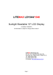
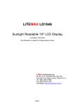
1
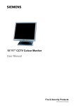
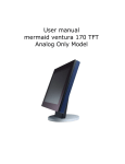
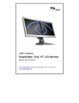
LITEMAX SLD1226 CCFL Backlight (1st Edition 8/24/2007 ) All information is subject to change without notice. Approved by Checked by Prepared by David Sharline Jack LITEMAX Electronics Inc. 8F-2, No.133, Lane 235, Bau-chiau Rd., Shin-dian City, Taipei County, Taiwan R.O.C. Tel : 886-2-8919-1858 Fax: 886-2-8919-1300 Homepage: http://www.litemax.com.tw Page 1 Content Content ............................................................................................................................. 2 Introduction ....................................................................................................................... 3 Hardware Installation ........................................................................................................ 3 Specification...................................................................................................................... 4 The Display Timing............................................................................................................ 6 The Display Outline Dimensions ....................................................................................... 7 The Display Controls......................................................................................................... 8 The Screen Adjustment..................................................................................................... 9 Page 2 Introduction Welcome to enjoy the fantastic sightseeing world. This new technology will bring you the whole new feeling about the “monitor”. We show here some of the major advantages of the LCD monitor. You will really find some other advantages when you use it. Hardware Installation This chapter will guide you the correct installation procedures of your LCD monitor. Unpacking After you unpack your LCD Monitor, please make sure that the following items are included in the carton and in good condition. If you find that any of these items are damaged or missing, please contact your dealer immediately. One LCD Monitor on its stand 15-pin D-sub Video cable (Option) Audio cable (Option) AC/DC adapter with 12V DC output (Option) AC power cord (Option) Quick installation Guide User’s manual Installation This analog LCD display does not require any special drivers. Necessary drivers are supplied by the video card manufacturer and may be found on the diskettes supplied with the video card that came with your computer. Windows 98/2000/XP drivers for both the display and the video card are supplied on the Windows 98/2000/XP CD or diskettes. Unfortunately, Microsoft did not provide a complete listing of the displays on the initial retail release. You may use the standard XGA (1024x768) as the display type. The video card must also be set up correctly in Windows 98/2000/XP and make sure the video output of the VGA card is on list in Section 6.1 or check your Video Card manual or Windows 98/2000/XP Read me file for further information on Video Card. After the question listed above is solved, we continue the setup procedure as below. 1. Turn power off both Computer and Display before making any connection. 2. Install Display on the solid horizontal surface such as a table or desk. 3. Connect the power cable and the AC/DC adapter, then connect adapter toe the back of the LCD monitor. 4. The LCD monitor comes with a 15-pin video cable; you may use this cable for both IBM PC’s & compatibles and Macintosh. 5. Tighten the screws of the Display cable until the connectors are fastened securely. 6. Switch on power to the Computer system, then to the monitor. Page 3 Specification Model No. Display Area LCD Display Display Colors Luminance Contrast Ratio Resolution Pixel Arrangement Pixel Pitch Viewing Angle Color Gamut Response Time Sync Signal Connector F/R Control Button OSD Menu Power Consumption Module Size Weight (Net) LD1226 245.76 (H) x 184.32 (V) mm 12.1" TFT active matrix 262,144 colors 1250 cd/m2 (typ.) 250:1 (typ.) 1024 x 768 (XGA) RGB (Red, Green, Blue) vertical stripe 0.24 (H) x 0.24 (V) mm +70°~-70°(H), +55°~-70°(V) At LCD panel center 60% (typ.) [against NTSC color space] Ton (black 10%→white 90%) 50 ms (Max) LVDS 15 Pin D-sub Power Switch, Menu, Select (+,-), Auto Brightness, Contrast, H/V Position, Color, Phase, Clock, Language, Management At maximum luminance and checkered flag pattern 32W (typ.) 338(H) x 278 (V) x 59.3 (D) mm 3.07kg (typ.) ※Specifications subject to change without notice. Page 4 The following picture provides the connection outline 15 Pin D-s ub A C/DC A dapte r Power Cor d Video Input Pin Assignment This section describes the pin assignment of the LCD’s video connector. 15pin Mini D-sub connector. Pin No. 1 2 3 4 5 6 7 8 9 10 10 5 1 15 11 6 Signal Connector Red Video Signal Green Video Signal Blue Video Signal N.C. Ground Ground for red video signal Ground for green video signal Ground for blue video signal N.C. Ground Page 5 It is called 11 12 13 14 15 N.C. DDC data Horizontal sync signal Vertical sync signal DDC clock The Display Timing Applicable video timing The following table lists the better display quality modes that the LCD monitor provides. If the other video modes are input, the monitor will stop working or display unsatisfactory picture quality. VESA Modes Mode Resolution DOS VGA 720x400@70Hz 640x480@60Hz 640x480@72Hz 640x480@75Hz SVGA 800x600@56Hz 800x600@60Hz 800x600@72Hz 800x600@75Hz XGA 1024x768@60Hz 1024x768@70Hz 1024x768@75Hz IBM Modes EGA 640x350@70Hz DOS 720x400@70Hz VGA 640x480@60Hz XGA 1024x768@72Hz MAC Modes VGA 640x480@60Hz SVGA 832x624@75Hz XGA 1024x768@75Hz Total 900x449 800x525 832x520 840x500 1024x625 1056x628 1040x666 1056x625 1344x804 1328x806 1312x800 Nominal Frequency ±0.5KHz 31.469 31.469 37.861 37.500 35.156 37.879 48.077 46.875 48.363 56.476 60.023 Nominal Frequency ±0.5KHz 70.087 59.940 72.809 75.000 56.250 60.017 72.188 75.000 60.004 70.069 75.029 Nominal Pixel Clock (MHz) 28.322 25.175 31.500 31.500 36.000 40.000 50.000 49.500 65.000 75.000 78.750 800x449 900x449 800x525 1304x798 31.469 31.469 31.469 57.515 70.086 70.087 75.000 72.100 25.175 28.322 31.500 75.000 800x525 1152x667 1328x804 31.469 49.725 60.927 59.940 74.551 74.927 25.175 57.2832 80.000 Page 6 The Display Outline Dimensions Unit: mm VR L ightse nsor S mar t B oar d Page 7 The Display Controls Membrane Control Button POWER SWITCH: Pushing the power switch will turn the monitor on. to turn the monitor off. Pushing it again Power LED: Power ON-Green / Power off-No. Up Key >: Increase item number or value of the selected item. When OSD is off, it is Hot key for brightness change: MAX►TV►Game►PC Menu Key: Enter to the OSD adjustment menu. It also used for go back to previous menu for sub-menu, and the change data don’t save to memory. Down Key <: Decrease item number or item value when OSD is on. When OSD is off, it is hot key for input switch between VGA, S-video, AV1, and AV2 Screen Adjustment Operation Procedure 1. 2. 3. 4. 5. Entering the screen adjustment The setting switches are normally at stand-by. Push the MENU button once to display the main menu of the screen adjustment. The adjustable items will be displayed in the main menu. Entering the settings Use the Adjust< and Adjust> buttons to select the desired setting icon and push the SELECT button to enter sub-menu. Change the settings After the sub-menu appears, use the Adjust< and Adjust> buttons to change the setting values. Save After finishing the adjustment, push the SELECT button to memorize the setting. Return & Exit the main menu Exit the screen adjustment; push the “MENU” button. When no operation is done around 45 sec (default OSD timeout), it goes back to the stand-by mode and no more switching is accepted except MENU to restart the setting. Page 8 The Screen Adjustment Main Menu You can adjust the brightness, contrast, display colors, the horizontal and vertical position of the display and OSD language, etc. through the main menu display. The OSD Menu is displayed on screen when MENU key is pressed. The OSD menu is a combination of graphic and text display. The first line always shows the current selected or active menu item. The bottom line of main menu shows information of the input image. The LEFT and RIGHT keys are used to scroll through items within the menu. The selected item is highlighted as the scrolling move along. The SELECT key is used to activate the highlighted item. During this state, MENU key is used to close the OSD menu from the screen. (OSD picture may vary on different AD board.) The OSD adjusting menu: Input Source Auto Adjust Select this function can make the monitor have the best efficiency. Brightness/ Setup the brightness of the panel. / The Contrast Contrast menu item is used to adjust image contrast. Image Adjust Configure the image frequency. Color Adjust Configure the image color. Volume Adjust Setup the image position within the panel. Language There are 8 type languages can be selected. Reset Restart the setting. Exit Exit setting. ※Note: If you don’t press any key during 45 seconds, the OSD will disappear by itself and not save the parameters. Page 9