Download Toro Drip In Classic Soaker Dripline Data Sheet
Transcript
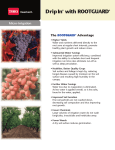
Drip In® Classic Turbulent Flow Dripline Micro-Irrigation I MP R OVED C R OP YI ELD AND QU ALI TY • Water distributed evenly over all rows in the irrigated area. • Fewer weeds from surface water. • Precise application of fertilizers. • Better control of plant stress. • Harvest timing becomes controllable. • Crops can be irrigated during harvesting to maximize total yield. C U LT U R AL C OS T BENEF I T S • Less irrigation water applied during growing season. • Quantity of fertilizers can be reduced. • Reduced labor costs for irrigation and harvesting. The Drip In® Emitter T HE I N- LI NE EMI T T ER Inserted in the tube... becomes a permanent part of it. Drip In Classic is the most effective and economical choice for most permanent applications. The hose with the integral in-line emitter is rugged and lightweight for easy installation and retrieval. The in-line emitter, with it’s proven turbulent flow path design and raised inlets, offers high resistance to clogging for the most demanding of applications. • The in-line emitter is a labyrinth type, turbulent flow dripper. The emitter is enclosed and inseparably welded to the inside wall of the tubing as it is extruded in the manufacturing process. This emitter has enjoyed over 20 years of reliable performance in a variety of applications. • Classic ® Dripline is a one piece emitter enclosed tube. It is rugged, lightweight and very flexible. It can be laid out and re-rolled easily with no damage to the in-line emitters. Only the highest quality resins are used. Drip In ® dripline is the most effective and economical choice for permanent or row crops. Classic dripline now comes with the Toro MicroIrrigation Blue Stripe ® of quality. AD VANTAGES • H ighly clog-resistant due to wide, deep turbulent passage ways and raised inlets. • Dual-opposed outlets. • Extremely accurate flow rate due to high quality control standards. • Reduced labor and installation cost. No hole punching, lost emitters or handling damage. • Lower friction loss allows longer runs and fewer mainlines. • Flow rate can be varied according to crop requirements. • For above and below ground applications.* • E mitters are factory pre-installed, thus requiring no field installation (hole punching, clip-ons, etc.). Note: For subsurface applications, we recommend Drip In ® with Rootguard ®. Drip In Classic ® 0.550" (16mm) Drip In Classic Dripline ® Drip In® Classic Spacings: ® 0. 5 50 ( 16M M) D RIP IN CL A S S IC D R I P LI NE 10 8 6 5 4 8 6 5 4 3 9 7 Head Loss (psi) 7 3 2 2 1 1 0 0 0 100 200 300 400 500 600 Dripline Length (feet) 700 800 900 0 1000 Head Loss v. Dripline Length and Emitter Spacing Drip In 16mm 1.0 GPH Emitter 0% Slope. 200 9 9 8 8 7 6 4 5 Head Loss (psi) 400 500 600 Dripline Length (feet) 700 800 Head Loss v. Dripline Length and Emitter Spacing Drip In 16mm 1.8 GPH Emitter 0% Slope. 7 6 2 1 1 0 0 Color of GPH @ 15 psi Emitter 100 200 300 400 Dripline Length (feet) 500 600 700 Emitter 0Flow 100 0.550" I.D./0.640" O.D./0.045" Wall Emitter Spacing Inches Centimeters 18" 24" 30" 36" 42" 48" 60" 45 60 75 90 105 125 150 0.75 1.00 1.80 Pressure (psi) 10 200 300 Dripline 15 Length 20 (feet) 25 0.34 0.42 0.49 0.43 0.53 0.62 Brown 0.61 0.75 0.87 Pressure (psi) 1.16 1.00 Greenof 0.81 Color Emitter 10 1.80 15 2.09 20 1.46 Blue Black Black 0.53 of Emitter is asBlack Color Coding shown. Flow Rate vs. Pressure 0.42 0.53 0.75 1.00 Emitter Flow GPH 1.80 @ 15 psi 4 2 0 5 3 300 10 10 3 100 Head Loss (psi) Head Loss v. Dripline Length and Emitter Spacing Drip In 16mm .75 GPH Emitter 0% Slope. Head Loss (psi) Head Loss v. Dripline Length and Emitter Spacing Drip In 16mm .53 GPH Emitter 0% Slope. 9 10 Brown Green Blue 0.43 0.61 0.81 1.46 0.53 0.75 1.00 1.80 0.62 0.87 1.16 2.09 30 400 35 40 500 0.55 0.60 0.65 0.70 0.69 0.76 0.82 0.88 Rate1.15 vs. Pressure 0.97 Flow 1.06 1.22 1.31 1.44 1.57 1.68 25 2.58 30 2.80 35 3.00 40 2.35 0.69 0.97 1.31 2.35 0.76 1.06 1.44 2.58 0.82 1.15 1.57 2.80 0.88 1.22 1.68 3.00 16mm Dripline Run Length Color Coding of Emitter is as shown. Maximum Run for a Flow Variation ±5% 0.550” I.D./0.640” O.D./0.045” 0.42 gph 1.5 lph 0.53Wall gph 2.0 lph 0.75 gph 2.8 lph Maximum for a Flow Variation Feet Meters Feet RunMeters Feet ±5% Meters Emitter Spacing 0.53 2.0 0.75 2.8 315 96 254gph 77 lph 201gph 61lph Inches Centimeters Feet Meters Feet Meters 390 119 317 97 254 77 18" 45 254 77 201 61 434 132 374 114 300 97 24" 60 317 97 254 77 515 157 428 130 345 105 30" 75 374 114 300 97 575 175 478 146 392 119 36" 90 428 130 345 105 42" 105 478 146 392 119 630 192 526 160 428 130 48" 125 526 160 428 130 735 224 616 188 474 144 60" 150 616 188 474 144 1.0gph. Feet 1.0gph. 165 Feet 205 165 228 205 270 228 300 270 300 330 330 385 385 Run Length 3.78 lph 16mm 1.80Dripline gph 6.81 lph Meters Feet Meters 3.78 1.80 6.81 50 lph 125gph 38 lph Meters Feet Meters 62 150 46 50 125 38 69 172 52 62 150 46 82 205 6252 69 172 91 225 6962 82 205 91 225 101 250 7669 101 250 117 290 8876 117 290 88 Maxiumum length of run based on EU and minimum pressures – please contact Toro for length of run based on other criteria such as flushing velocity. Flow Discharge Equations 0.42 = 0.103 P 0.52 Q = Flow rate (gph) 0.53 = 0.130 P 0.52 0.75 = 0.194 P 0.50 P = Operating Pressure (psi) 1.00 = 0.238 P 0.53 Barb Loss Factor (kd) 0.90 1.80 = 0.440 P 0.53 0.620" (18mm) Drip In Classic Dripline ® Drip In® Classic Spacings: ® 0. 6 20 ( 18 M M ) D RIP IN CL A S S IC DR I P LI NE Head Loss v. Dripline Length and Emitter Spacing Drip In 18mm .53 GPH Emitter 0% Slope. 10 10 7 5 4 8 6 9 Head Loss (psi) Head Loss (psi) 9 7 4 3 5 2 8 6 3 2 1 1 0 0 100 200 300 400 500600 700 800 900 Dripline Length (feet) 1100 0 1200 Head Loss v. Dripline Length and Emitter Spacing Drip In 18mm 1.8 GPH Emitter 0% Slope. 8 7 6 700 9 100 10 400 200 300 500 600 Dripline Length (feet) 0 1000 Head Loss (psi) Head Loss v. Dripline Length and Emitter Spacing Drip In 18mm 1.0 GPH Emitter 0% Slope. 5 4 3 2 Flow Rate vs. Pressure 1 0 0 100 Flow 200 Discharge Equations 300 400 = 0.130 P 0.75 = 0.194 P 0.50 1.00 = 0.238 P 0.53 1.80 = 0.440 P 0.52 Dripline Length (feet) 0.53 Q = Flow rate (gph) P = Operating Pressure (psi) Barb Loss Factor (kd) 0.40 500 0.52 Emitter Flow Color of 600 GPH @ 15 psi Emitter Pressure (psi) 10 GPH of @Emitter 15 psiis as shown. Emitter Color Coding 0.53 1.00 1.80 0.620" I.D./0.710" O.D./0.045" Wall Emitter Spacing Inches Centimeters 18" 24" 30" 36" 42" 48" 60" 45 60 75 90 105 125 150 15 20 0.53 0.43 0.53 0.62 Black Brown 0.61 0.75 0.87 0.75 1.00 Green 0.81 1.00 1.16 Emitter Flow Blue Color 1.46 of Pressure 1.80 1.80 (psi) 2.09 Black Green Blue 10 0.43 0.81 1.46 15 0.53 1.00 1.80 25 0.69 0.97 1.31 2.35 20 0.62 1.16 2.09 30 35 40 0.76 0.82 0.88 1.06 1.15 1.22 Flow 1.57 Rate vs. Pressure 1.44 1.68 2.58 2.80 3.00 25 0.69 1.31 2.35 30 0.76 1.44 2.58 35 0.82 1.57 2.80 40 0.88 1.68 3.00 Color Coding of Emitter is as shown. 18mm Dripline Run Length Maximum Run for a Flow Variation ±5% Wall 2.8 lph 18mm Dripline 0.530.620” gph I.D./0.710” 2.0 lph O.D./0.045” 0.75 gph 1.0 gph 3.78 lph 1.80 gph 6.81Run lphLength MaximumMeters Run for a FlowFeet Variation ±5% Feet Meters Feet Meters Feet Meters Emitter Spacing 330 101 2650.53 gph 81 2.0 lph 2251.0gph. 69 3.78 lph 1511.80 gph 46 6.81 lph Inches Centimeters 410 125 330 Feet 101 Meters 282 Feet 86 Meters 186 Feet 57 Meters 18” 45 330 101 225 69 151 46 460 140 310 119 322 98 217 66 24” 60 410 125 282 86 186 57 545 30” 166 75 444 460 135 140 369 322 112 98 250 217 76 66 620 36” 189 90 497 545 151 166 410 369 125 112 276 250 84 76 670 42” 204 105 544 620 166 189 452 410 138 125 304 276 93 84 775 48” 236 125 635 670 194 204 524 452 160 138 355 304 108 93 60” 150 775 236 524 160 355 108 Maxiumum length of run based on EU and minimum pressures – please contact Toro for length of run based on other criteria such as flushing velocity. 800 0.710" (20mm) Drip In Classic Dripline ® ® Drip In® Classic Spacings: 0. 7 10 ( 2 0 M M ) DRIP IN CL A S S IC D R I P LI NE Head Loss v. Dripline Length and Emitter Spacing Drip In 20mm .53 GPH Emitter 0% Slope. 7 10 9 8 6 5 Head Loss (psi) 8 4 7 6 5 4 3 Head Loss v. Dripline Length and Emitter Spacing Drip In 20mm 1.0 GPH Emitter 0% Slope. Head Loss (psi) 9 10 3 2 2 1 0 0 100 200 300 400 500 600 700 800 900 Dripline Length (feet) 1000 1100 1200 1 0 1300 1400 0 1500 200 300 400 500 600 Dripline Length (feet) 700 800 900 1000 Flow Rate vs. Pressure Emitter Flow GPH @ 15 psi 0.53 1.00 Pressure (psi) 10 15 0.43 0.53 0.81 1.00 Color of Emitter Brown Green 20 0.61 1.16 25 0.68 1.31 30 0.75 1.44 35 0.81 1.57 40 0.87 1.68 Color Coding of Emitter is as shown. 0.710” I.D./0.805” O.D./0.045” Wall 100 Emitter Spacing Inches 18” 24” 30” 36” 42” 48” 60” Centimeters 45 60 75 90 105 125 150 20mm Dripline Run Length Maximum Run for a Flow Variation ±5% 0.53 gph 2.0 lph 1.0 gph 3.78 lph Feet Meters Feet Meters 395 120 271 83 493 150 338 103 582 177 397 121 666 203 453 138 744 227 507 155 820 250 556 169 958 292 170 170 Maxiumum length of run based on EU and minimum pressures – please contact Toro for length of run based on other criteria such as flushing velocity. Other Drip In® Products Flow Discharge Equations DripIn Clipperline ® Flow Rate vs. Pressure DripIn with 0.42 = 0.103 P 0.53 = 0.130 P ® ROOTGUARD 1.00 = 0.238 P ® ® 0.52 Emitter Flow Color of GPH @ 15 psi Emitter Pressure (psi) 10 15 ® 20 30 35 DripIn PC 25 Dripline 40 0.42 0.34 0.42 0.49 0.55 0.60 0.65 0.70 Black dripline 0.53 Black Pressure 0.53 0.43 0.53compensating 0.61 0.68 0.75 0.81 for 0.87use in adverse topographical and operating 0.52 1.65 = 0.404 P 1.00 0.81 1.00 1.16 1.31 1.44 1.57 1.68 Green In Dripline is also available with conditions. Brick Red 1.65 1.34 1.65 1.92 2.15 2.37 2.56 2.75 ROOTGUARD protection. ROOTGUARD Q = Flow rate (gph) P = Operating Pressure (psi) Barb Loss Factor (kd) 0.35 Drip Drip In dripline comes factory-installed • Dramatically reduces labor and installation time in the field. 0.52 Color Coding of Emitter is as shown. technology combines Treflan® with DripIn® Soaker Dripline the drip emitter to inhibit root growth. 1/4" (6mm) This is a patented technology where • Unique engineering plastics provide the herbicide is released at a uniform unparalleled strength on0.710" the wire. I.D./0.805" O.D./0.045" Wall Classic (non-compensating) dripline for Dripline Run Length rate over a long period of time. It 20mm greenhouse, nurseries and other small • Superior control of water placement by ±5% maintains a sufficient in Maximum Runconcentration for a Flow Variation applications. directing water droplet toEmitter the plant.Spacing the soil thelph 0.42immediately gph 1.5 lph surrounding 0.53 gph 2.0 1.0 gph 3.78 lph 1.65 gph 6.25 lph drip emitter, toMeters prevent root Centimeters Feet Feetgrowth Meters Feet Meters Feet Meters • Low profile for mechanicalInches harvesting. 18" 45 into the 480 395 120 271 83 201 61 dripper.146 • Works with 14 gauge wire. 24" 60 48" 125 150 With Clipperline, we do the30" work in 75 the factory to save you time, 36"labor and90 money in the field. 42" 105 ©2014 The Toro Company 60" Micro-Irrigation Business 1588 N. Marshall Avenue, El Cajon, CA 82020-1523, USA Tel: +1 (800) 333-8125 or +1 (619) 562-2950 Fax: +1 (800) 892-1822 or +1 (619) 258-9973 toro.com DLT001 06/14 595 675 790 880 965 1120 181 206 241 268 294 341 493 582 666 744 820 958 150 177 203 227 250 292 338 397 453 507 556 170 103 121 138 155 169 170 246 292 327 367 404 445 75 89 100 112 123 136


